EP1065531B1 - Low refractive index high dispersion optical material and method of production - Google Patents
Low refractive index high dispersion optical material and method of production Download PDFInfo
- Publication number
- EP1065531B1 EP1065531B1 EP00305499A EP00305499A EP1065531B1 EP 1065531 B1 EP1065531 B1 EP 1065531B1 EP 00305499 A EP00305499 A EP 00305499A EP 00305499 A EP00305499 A EP 00305499A EP 1065531 B1 EP1065531 B1 EP 1065531B1
- Authority
- EP
- European Patent Office
- Prior art keywords
- refractive index
- dispersion
- particles
- optical
- tio
- Prior art date
- Legal status (The legal status is an assumption and is not a legal conclusion. Google has not performed a legal analysis and makes no representation as to the accuracy of the status listed.)
- Expired - Lifetime
Links
Images


Classifications
-
- G—PHYSICS
- G02—OPTICS
- G02B—OPTICAL ELEMENTS, SYSTEMS OR APPARATUS
- G02B1/00—Optical elements characterised by the material of which they are made; Optical coatings for optical elements
- G02B1/04—Optical elements characterised by the material of which they are made; Optical coatings for optical elements made of organic materials, e.g. plastics
Definitions
- the present invention relates to an optical material and an optical system using it and, more particularly, to a low refractive index high-dispersion optical material, for example, applicable to optical elements such as lenses, filters, mirrors, refracting optical elements, diffracting optical elements, and so on, and an optical system of optical equipment such as cameras, binoculars, microscopes, and so on, using the optical material.
- a low refractive index high-dispersion optical material for example, applicable to optical elements such as lenses, filters, mirrors, refracting optical elements, diffracting optical elements, and so on
- an optical system of optical equipment such as cameras, binoculars, microscopes, and so on
- Such diffracting optical element can be provided with an aspherical-lens-like effect by changing periods of the periodic structure of the diffraction grating and is thus greatly effective to reduction of aberration.
- a ray appears as one ray even after refracted by a lens surface, whereas a ray appears as a plurality of rays of plural orders after diffracted by a diffractive surface.
- the diffracting optical element When the diffracting optical element is used as a lens system, it is thus necessary to determine the grating structure so as to concentrate light of the used wavelength range into specific orders (which will also be referred to hereinafter as "designed orders") by adequately enhancing the diffraction efficiency of rays of the designed orders.
- specific orders which will also be referred to hereinafter as "designed orders”
- the intensity of rays of diffracted light of the other orders is low.
- diffracted light thereof appears null. If there exist rays of diffraction orders other then the designed orders, they will be focused at positions different from those of the rays of the designed orders and appear as flare light.
- the layouts capable of reducing this decrease of diffraction efficiency are presented in Japanese Patent Application Laid-Open No. 9-127321 and Japanese Patent Application Laid-Open No. 11-44808 .
- the layouts realize high diffraction efficiency in a wide wavelength range by optimizing dispersion properties and thicknesses of gratings of materials different from each other.
- the diffracting optical elements wherein a plurality of optical materials (layers) are stacked on a substrate and wherein the diffraction grating is formed in the step shape, kinoform, or binary shape resulting from approximation thereof to the step shape, or the like in at least one of interfaces between the mutually different optical materials.
- the combination of a relatively high-refraction low-dispersion material with a relatively low-refraction high-dispersion material is used in order to obtain the layout having the high diffraction efficiency in the wide wavelength range.
- An object of the present invention is to provide an optical material with low refractive index and high dispersion, which was not known heretofore, and an optical system using it.
- the present invention provides a method for producing a low refractive index high dispersion optical material wherein the relation between the refractive index for the d-line (n d ) and the Abbe number ( ⁇ d ) of said optical material is defined as follows: n d ⁇ - 6.667 ⁇ 10 - 3 ⁇ ⁇ d + 1.70 said method comprising mixing first and second materials, said first material having a refractive index of not more than 1.45 for the d-line and said second material having an Abbe number of not more than 25, as defined in independent claim 1.
- the present invention provides a low refractive index high dispersion optical material wherein the relation between the refractive index for the d-line (n d ) and the Abbe number ( ⁇ d ) of said optical material is defined as follows: n d ⁇ - 6.667 ⁇ 10 - 3 ⁇ ⁇ d + 1.70 said optical material comprising a mixture of first and second materials, said first material having a refractive index of not more Lean 1.45 for the d-line and said second material having an Abbe number of not more than 25, as defined in independent claim 14.
- Supposing particles have the size of 2 to 100 nm, the polarization characteristics inside the particles will be like those of bulk.
- the polarization characteristics for the light in the visible wavelength range of 400 to 700 nm are of a level in which nonuniformity thereof can be ignored in an optical sense. Therefore, the structure as illustrated in Fig. 2 demonstrates the optical characteristics close to the Drude theory of Eq. (2) below.
- n 1 refractive index of bulk
- Fig. 3 is an explanatory diagram to show the relationship between refractive index n d and Abbe's number ⁇ d with various filling factors of substance. As seen from Fig. 3 , the refractive index n d , and dispersion ⁇ d vary as indicated by curves S1, S2, S3, and with variation in apparent density by changing the filling factors, the refractive index demonstrates change while the Abbe's number little change.
- a substance can be prepared in the region of ( n d ⁇ -6.667 ⁇ 10 -3 ⁇ d + 1.70, ⁇ d ⁇ 40, and n d ⁇ -0.01 ⁇ d + 1.70, ⁇ d ⁇ 40) by decreasing the refractive index in the structure of Fig. 2 .
- the filling factor of the film is lowered depending upon conditions of deposition and the structure becomes as illustrated in Fig. 2 , whereby the refractive index of the material with large wavelength dispersion (small Abbe's number ⁇ d ) is decreased to some extent.
- a material with a low refractive index and high dispersion small Abbe's number is realized by first decreasing the filling factor of the substance with large wavelength dispersion of refractive index (hereinafter referred to as "dispersion") (a high-dispersion substance) and filling gaps in this substance with another low-index substance with a small refractive index, as in (3) of Fig. 4 .
- n x refractive index of bulk of each material.
- the dispersion shows little change but the refractive index does a shift toward lower indexes when the high-index high-dispersion material is mixed with a lower-index material; and the refractive index demonstrates little change but the dispersion increases when the high-index high-dispersion material is mixed with a higher-dispersion material.
- any method may be employed as long as the size is smaller than the wavelengths of light and makes little contribution to scattering (i.e., if the size is in units not more than 100 nm).
- applicable methods include two-dimensional evaporation of the large-dispersion material and the low-index material, formation of equivalent layers by depositing the respective materials in units of several nm, and so on.
- n 2 ⁇ C 1 ⁇ n 1 2 / ⁇ 1 ⁇ n 1 2 + 2 ⁇ + ⁇ C 2 ⁇ n 2 2 / ⁇ 2 ⁇ n 2 2 + 2 ⁇ / ⁇ C 1 / ⁇ 1 ⁇ n 1 2 + 2 ⁇ + ⁇ C 2 / ⁇ 2 ⁇ n 2 2 + 2 ⁇
- the blending materials can be either organic or inorganic materials if they are the material having large dispersion and the material indicating the property of low refractive index.
- the materials are the following materials.
- the optical material in the region of (n d ⁇ -6.667 ⁇ 10 -3 ⁇ d + 1.70, ⁇ d ⁇ 40) can be realized by using the low-index material of n a ⁇ 1.45 and particles of the large-dispersion material of ⁇ d ⁇ 25 in the grain size of 2 to 100 nm.
- the low-index material is desirably one of the amorphous fluororesins.
- the amorphous fluororesins have low refractive indexes, are stable and less reactive, and give rise to less deviation from calculated values in the form of mixtures.
- the material with large dispersion i.e., with a small Abbe's number
- it is desirably particles of a composite metal oxide of titanium and silicon (Si x -Ti (1-x) O 2 ).
- the ratio of metals can be adjusted to an arbitrary value for the composite metal oxide of titanium and silicon and it is thus easy to adjust the Abbe's number.
- the large-dispersion material used herein is the particles of the composite metal oxide of titanium and silicon adjusted to the Abbe's number ( ⁇ d ) of 24.5 ⁇ 25.
- the grain size of the particles of the composite metal oxide of Ti and Si is desirably not more than 100 nm.
- the resultant optical material is one satisfying the region ⁇ n d ⁇ -6.667 ⁇ 10 -3 ⁇ d + 1.70, ⁇ d ⁇ 40).
- the optical material in the region (n d ⁇ -6.667 ⁇ 10 -3 ⁇ d + 1.70, ⁇ d ⁇ 40) is obtained by mixing the material with the low index (n d ⁇ 1.45) and the material with the large wavelength dispersion of refractive index ( ⁇ d ⁇ 25).
- the low-index high-dispersion optical material is realized as described above.
- the method with this 2-ethoxy-ethyl methacrylate provides less freedom for adjusting the levels of refractive index and wavelength dispersion than the method of the present embodiment.
- the optical material is realized in the region of (n d ⁇ -0.01 ⁇ d + 1.70, ⁇ d ⁇ 40) by using the low-index material of n d ⁇ 1.40 and particles with ⁇ d ⁇ 15 and in the particle size of 2 to 100 nm as the large-dispersion material.
- the low-index material is desirably one of the amorphous fluororesins.
- the amorphous fluororesins have the low refractive indexes, are stable and less reactive, and thus give rise to less deviation from calculated values in the form of mixtures.
- the large-dispersion material for realizing the above optical material, but it is desirably particles of TiO 2 .
- the TiO 2 particles are relatively easily available and belong to the class of materials indicating the highest dispersion out of the particles for optical use commercially available commonly.
- the particle size of the TiO 2 particles is preferably not more than 100 nm.
- the above TiO 2 particles for example, in the aforementioned amorphous fluororesins, it is effective to modify the surface of the TiO 2 particles by a fluorophilic group like the fluoroalkyl group.
- the optical material obtained satisfies the region (n d ⁇ -6.667 ⁇ 10 -3 ⁇ d + 1.70, ⁇ d ⁇ 40); when the ratio is in the range of 90:100 to 40:100, the optical material satisfies the region (n d ⁇ -0.01 ⁇ d + 1.70, ⁇ d ⁇ 40).
- the optical material can be obtained in the region (n d ⁇ -6.667 ⁇ 10 -3 ⁇ d + 1.70, ⁇ d ⁇ 40) or in the region (n d ⁇ -0.01 ⁇ d + 1.70, ⁇ d ⁇ 40).
- ITO Indium Tin oxide
- ⁇ d 1.8581, 5.53
- ITO 1.8581, 5.53 has the Abbe's number ( ⁇ d ) of half or less those of the other high-dispersion materials and thus demonstrates extremely high dispersion.
- PMMA polymethyl methacrylate
- APO amorphous polyolefin
- MS copolymers of methyl methacrylate and styrene
- ITO is an electrically conductive substance, it can also reduce adhesion of dust to the lens surface due to charging specific to the optical resins for optical use.
- ITO Since ITO shows absorption in the ultraviolet region, it acts as a UV absorber and thus relieves deterioration of the resin due to ultraviolet rays.
- the optical material in the region of (n d ⁇ -6.667 ⁇ 10 -3 ⁇ d + 1.70, ⁇ d ⁇ 40) can be realized by using the material of 1.45 ⁇ n d ⁇ 1.55 as the low-index material and using the particles having ⁇ d ⁇ 10 and the particle size of 2 to 100 nm as the large-dispersion material.
- ITO Indium Tin Oxide
- ⁇ d 1.8581, 5.53
- the particle size of the particles of ITO is desirably not more than 100 nm.
- ITO is the electroconductive material, the chargeability of the above optical materials is also reduced.
- the method with 2-ethoxy-ethyl methacrylate provides less freedom for adjusting the levels of refractive index and index dispersion than the method of the present embodiment.
- optical materials according to the present invention will be described below.
- a fluorine solvent the molecular structure of (C 4 F 9 ) 3 N
- the percentage of the amorphous fluororesin to the solvent was 4%.
- a coating of each of the above solutions was formed on a substrate of BK7 of ⁇ 45 ⁇ 2t by a dip coat method and was heated in a furnace at 180°C for 20 minutes to obtain a film of the mixture of the amorphous fluororesin and the particles of Si x -Ti (1-x) O 2 .
- the refractive index and dispersion of the above mixture films were measured by a spectral ellipsometer (VASE: available from J. A. Woollam. Co., Inc.).
- the two-side (front side and back side) reflectance and transmittance of the above mixture films were measured by a spectrophotometer (U4000: available from Hitachi, Ltd.).
- absorption-scattering (rate) 1 - ( two - side reflectance ) - ( transmittance ) .
- the absorption-scattering (rate) of the mixtures is not more than 0.01, they can be used as optical films without problems.
- the absorption-scattering (rate) thereof was not more than 0.01, and the mixture can be used as an optical film without problems.
- the mixture at the ratio of Si x -Ti (1-x) O 2 : amorphous fluororesin 88.5:100 showed great scattering with the absorption-scattering (rate) of 0.04 and the refractive index and index dispersion thereof were unmeasurable.
- the percentage of the amorphous fluororesin to the solvent was 4%.
- a coating of each of the above solutions was formed on the substrate of BK7 of ⁇ 49 ⁇ 2t by the dip coat method and was heated in the furnace at 180°C for 20 minutes to obtain a film of the mixture of the amorphous fluororesin and the particles of Si x -Ti (1-x) O 2 .
- the refractive index and dispersion of the above mixture films were measured by the spectral ellipsometer (VASE: available from J. A. Woollam. Co., Inc.).
- the two-side reflectance and transmittance of the above mixture films were measured by the spectrophotometer (U4000: available from Hitachi, Ltd.).
- absorption-scattering (rate) 1 - ( two - side reflectance ) - ( transmittance ) .
- the percentage of the amorphous fluororesin to the solvent was 4%.
- a coating of each of the above solutions was formed on the substrate of BK7 of ⁇ 49 ⁇ 2t by the dip coat method and was heated in the furnace at 180°C for 20 minutes to obtain a film of the mixture of the amorphous fluororesin and the particles of TiO 2 .
- the refractive index and dispersion of the above mixture films were measured by the spectral ellipsometer (VASE: available from J. A. Woollam. Co., Inc.).
- the two-side reflectance and transmittance of the above mixture films were measured by the spectrophotometer (U4000: available from Hitachi, Ltd.).
- absorption-scattering (rate) 1 - ( two - side reflectance ) - ( transmittance ) .
- the mixture had the absorption-scattering (rate) of not more than 0.01 and thus can be used as an optical film without problems.
- the mixture at the ratio of TiO 2 : amorphous fluororesin 120:100 demonstrated great scattering with the absorption-scattering (rate) of 0.06 and the refractive index and dispersion were unmeasurable.
- the percentage of PVA to the solvent was 4%.
- a coating of each of the above solutions was formed on the substrate of BK7 of ⁇ 49 ⁇ 2t by the dip coat method and thereafter it was heated in the furnace at 180°C for 20 minutes, thereby obtaining a mixture film of PVA and the TiO 2 particles.
- the refractive index and dispersion of the above mixture films were measured by the spectral ellipsometer (VASE: available from J. A. Woollam. Co., Inc.).
- the two-side reflectance and transmittance of the above mixture films were measured by the spectrophotometer (U4000: available from Hitachi, Ltd.).
- absorption-scattering (rate) 1 - ( two - side reflectance ) - ( transmittance ) .
- the height d of the grating was 8 ⁇ m and the diffraction efficiency was not less than 98% for the light at the wavelengths in the visible region of 400 to 700 nm.
- the height d of the grating is half that in Comparative Example 3 and this is advantageous in terms of forming of lens.
- MEK methyl ethyl ketone
- the percentage of PMMA to the solvent was 4%.
- a coating of each of the above solutions was formed on the substrate of BK7 of ⁇ 49 ⁇ 2t by the dip coat method and thereafter heated in the furnace at 80°C for 20 minutes, thereby obtaining a mixture film of PMMA and ITO particles.
- the refractive index and dispersion of the above mixture films were measured by the spectral ellipsometer (VASE: available from J. A. Woollam. Co., Inc.).
- the two-side reflectance and transmittance of the above mixture films were measured by the spectrophotometer (U4000: available from Hitachi, Ltd.).
- absorption-scattering (rate) 1 - ( two - side reflectance ) - ( transmittance ) .
- the mixture had the absorption-scattering (rate) of not more than 0.01 and thus can be used as an optical film without problems.
- the mixtures had the absorption-scattering (rates) of not more than 0.01 and thus can be used as optical films without problems.
- the percentage of PMMA to the solvent was 4%.
- a coating of each of the above solutions was formed on the substrate of BK7 of ⁇ 49 ⁇ 2t by the dip coat method and thereafter was heated in the furnace at 80°C for 20 minutes, thereby obtaining a mixture film of PMMA and TiO 2 particles.
- the two-side reflectance and transmittance of the above mixture films were measured by the spectrophotometer (U4000: available from Hitachi, Ltd.).
- absorption-scattering (rate) 1 - ( two - side reflectance ) - ( transmittance ) .
- the chargeability was measured with the electrostatic voltmeter after each sample was wiped twenty times with the wiping fabric (Savina Minimax: available from Kanebo Gosen K.K.). PMMA alone demonstrated the chargeability of 3 kV. The mixtures showed the chargeability of 1 kV to 2 kV.
- PC polycarbonate
- PMMA polymethyl methacrylate
- the percentage of the solute to the solvent of dichloroethane was 4%.
- a coating of each of the above solutions was formed on the substrate of BK7 of ⁇ 49 ⁇ 2t by the dip coat method and thereafter was heated in the furnace at 110°C for 20 minutes, thereby obtaining a mixture film of PC and ITO particles.
- the refractive index and dispersion of the above mixture films were measured by the spectral ellipsometer (VASE: available from J. A. Woollam. Co., Inc.).
- the two-side reflectance and transmittance of the above mixture films were measured by the spectrophotometer (U4000: available from Hitachi, Ltd.).
- absorption-scattering (rate) 1 - ( two - side reflectance ) - ( transmittance ) .
- a coating of each of the above solutions was formed on the substrate of BK7 of ⁇ 49 ⁇ 2t by the dip coat method and thereafter was heated in the furnace at 110°C for 20 minutes, thereby obtaining a mixture film of APO and ITO particles.
- the refractive index and dispersion of the above mixture films were measured by the spectral ellipsometer (VASE: available from J. A. Woollam. Co., Inc.).
- the two-side reflectance and transmittance of the above mixture films were measured by the spectrophotometer (U4000: available from Hitachi, Ltd.).
- absorption-scattering (rate) 1 - ( two - side reflectance ) - ( transmittance ) .
- the mixture had the absorption-scattering (rate) of not more than 0.01 and can be used as an optical film without problems.
- the mixtures had the absorption-scattering (rates) of not more than 0.01 and can be used as optical films without problems.
- the percentage of MS to the solvent was 4%.
- a coating of each of the above solutions was formed on the substrate of BK7 of ⁇ 49 ⁇ 2t by the dip coat method and thereafter was heated in the furnace at 80°C for 20 minutes, thereby obtaining a mixture film of MS and ITO particles.
- the refractive index and dispersion of the above mixture films were measured by the spectral ellipsometer (VASE: available from J. A. Woollam. Co., Inc.).
- the two-side reflectance and transmittance of the above mixture films were measured by the spectrophotometer (U4000: available from Hitachi, Ltd.).
- absorption-scattering (rate) 1 - ( two - side reflectance ) - ( transmittance ) .
- the mixture had the absorption-scattering (rate) of not more than 0.01 and can be used as an optical film without problems.
- the mixtures had the absorption-scattering (rates) of not more than 0.01 and can be used as optical films without problems.
- the height d of the grating was 9.98 ⁇ m and the diffraction efficiency was not less than 98% for the light at the wavelengths in the visible region of 400 to 700 nm.
- the height of the grating was approximately two thirds of that in Comparative Example 3 and this is advantageous in terms of forming of lens.
- the chargeability was measured with the electrostatic voltmeter after the sample was wiped twenty times with the wiping fabric (Savina Minimax: available from Kanebo Gosen K.K.). The sample showed no charge.
- the height d of the grating was 15 ⁇ m and the diffraction efficiency was not less than 98% for the light at the wavelengths in the visible region of 400 to 700 nm.
- the chargeability was measured with the electrostatic voltmeter after the sample was wiped twenty times with the wiping fabric (Savina Minimax: available from Kanebo Gosen K.K.). The sample showed the charge of 1 kV.
- the percentage of the dimethylsilicone resin to the solvent was 4%.
- a coating of each of the above solutions was formed on the substrate of BK7 of ⁇ 49 ⁇ 2t by the dip coat method and thereafter was heated in the furnace at 150°C for 20 minutes, thereby obtaining a mixture film of the dimethylsilicone resin and the TiO 2 particles.
- the refractive index and dispersion of the above mixture films were measured by the spectral ellipsometer (VASE: available from J. A. Woollam. Co., Inc.).
- the two-side reflectance and transmittance of the above mixture films were measured by the spectrophotometer (U4000: available from Hitachi, Ltd.).
- absorption-scattering (rate) 1 - ( two - side reflectance ) - ( transmittance ) .
- the mixtures had the absorption-scattering (rates) of not more than 0.01 and can be used as optical films without problems.
- the mixtures had the absorption-scattering (rates) of not more than 0.01 and can be used as optical films without problems.
- the mixture had the absorption-scattering (rate) of 0.02.
- silicone base surfactant 4 g was added to a solution containing 20 g of TiO 2 particles (5 to 20 nm) in 500 g of n-butanol, and thereafter 0.2 ml of 1N hydrochloric acid was added thereto. The solution was stirred at 25°C for 24 hours to modify the surface of the particles.
- n-heptane 250 g was added to the solution and the fractional distillation was conducted at 100°C to remove n-butanol, and alcohols etc. created by hydrolysis, thereby preparing the n-heptane solution in which the TiO 2 particles were dispersed.
- optical materials prepared according to the above method of the present embodiment are used for the optical systems such as image pickup optical systems, projection optical systems, illumination systems, and so on, or for the optical devices such as cameras, microscopes, binoculars, and so on.
- Each of the above examples permits attainment of the optical materials satisfying the region (n d ⁇ -6.667 ⁇ 10 -3 ⁇ d + 1.70, ⁇ d ⁇ 40) or n d ⁇ -0.01 ⁇ d + 1.70, ⁇ d ⁇ 40 and being indispensable for performance enhancement of the refracting optical systems and stack optical elements, and the optical systems using it.
- the optical material satisfying the low-index high-dispersion region (n d ⁇ -6.667 ⁇ 10 -3 ⁇ d + 1.70, ⁇ d ⁇ 40) can be realized by mixing the low-index material (n d ⁇ 1.45) with the large-dispersion material ( ⁇ d ⁇ 25) as described above.
- the low-index high-dispersion region (n d ⁇ -0.01 ⁇ d + 1.70, ⁇ d ⁇ 40) can be realized by mixing the low-index material (n d ⁇ 1.40) with the particles of the large-dispersion material ( ⁇ d ⁇ 15).
- the low-index high-dispersion region (n d ⁇ -6.667 ⁇ 10 -3 ⁇ d + 1.70, ⁇ d ⁇ 40) can also be realized by mixing the low-index material (1.45 ⁇ n d ⁇ 1.55) with the large-dispersion material ( ⁇ d ⁇ 10) as described above.
- PMMA polymethyl methacrylate
- APO amorphous polyolefin
- MS n d
- ITO is the electroconductive substance, it can reduce the chargeability of the above optical resin materials and thus can suppress decrease of transmitted light and increase of scattered light in the optical systems due to attachment of dust or the like.
Description
- The present invention relates to an optical material and an optical system using it and, more particularly, to a low refractive index high-dispersion optical material, for example, applicable to optical elements such as lenses, filters, mirrors, refracting optical elements, diffracting optical elements, and so on, and an optical system of optical equipment such as cameras, binoculars, microscopes, and so on, using the optical material.
- As one of conventional approaches to correction for chromatic aberration of the optical system composed of only refracting optics, there is a method of combining glass materials of different dispersion characteristics. For example, in the case of objectives of telescopes etc., axial chromatic aberration is corrected for by combining a positive lens of a low-dispersion glass material with a negative lens of a high-dispersion glass material. For this reason, there were cases where chromatic aberration was not corrected for adequately if the composition or the number of lenses was limited or if available glass materials were limited.
- For the purpose of correction for this chromatic aberration, there are suggestions on methods of controlling the refractive index and Abbe's number in order to expand the range of the optical constants of glass materials, thereby obtaining the low-refraction high-dispersion glass materials, for example, in Japanese Patent Application Laid-Open No.
6-32631 61-9262 4-33740 - On the other hand, other references, e.g. SPIE Vol. 1354 International Lens Design Conference (1990) etc., disclose methods of reducing the chromatic aberration by use of a diffracting optical element provided with a diffraction grating having diffracting action in part of a lens surface or an optical system, in contrast to the methods of reducing the chromatic aberration by the combination of glass materials.
US teaches lenses made of homo- or copolymers of fluorinated styrenes, which have refractive indices in the range of nD = 1,42-1,55 and Abbe numbers between 30 and 50.patent 4 420 225 - These methods make use of the physical phenomenon in which a refracting surface and a diffracting surface in the optical system demonstrate opposite directions of occurrence of chromatic aberration against rays of a certain reference wavelength.
- Further, such diffracting optical element can be provided with an aspherical-lens-like effect by changing periods of the periodic structure of the diffraction grating and is thus greatly effective to reduction of aberration.
- Comparing them herein as to refraction of rays, a ray appears as one ray even after refracted by a lens surface, whereas a ray appears as a plurality of rays of plural orders after diffracted by a diffractive surface.
- When the diffracting optical element is used as a lens system, it is thus necessary to determine the grating structure so as to concentrate light of the used wavelength range into specific orders (which will also be referred to hereinafter as "designed orders") by adequately enhancing the diffraction efficiency of rays of the designed orders. When light is concentrated in the specific orders, the intensity of rays of diffracted light of the other orders is low. When the intensity is zero, diffracted light thereof appears null. If there exist rays of diffraction orders other then the designed orders, they will be focused at positions different from those of the rays of the designed orders and appear as flare light.
- The layouts capable of reducing this decrease of diffraction efficiency are presented in Japanese Patent Application Laid-Open No.
9-127321 11-44808 - Specifically, they disclose the diffracting optical elements wherein a plurality of optical materials (layers) are stacked on a substrate and wherein the diffraction grating is formed in the step shape, kinoform, or binary shape resulting from approximation thereof to the step shape, or the like in at least one of interfaces between the mutually different optical materials.
- In each of the diffracting optical elements described in Japanese Patent Application Laid-Open No.
9-127321 11-44808 9-127321 11-44808 - For further enhancing the optical performance of the aforementioned diffracting optical elements, we investigated the optical materials commercially available, or the optical materials under research and development and obtained the distribution as illustrated in
Fig. 1 . - The materials of the stack diffracting optical elements described in the Japanese Patent Applications Laid-Open No.
9-127321 11-44808 Fig. 1 . - As for the materials suggested in the aforementioned Japanese Patent Applications Laid-Open No.
6-32631 61-9262 4-33740 Fig. 1 . - It is seen that 2-ethoxy-ethyl methacrylate (nd = 1.483, νd = 32) seems only one material with low refractive index and high dispersion and that there have been few such materials developed.
- An object of the present invention is to provide an optical material with low refractive index and high dispersion, which was not known heretofore, and an optical system using it.
- In a first aspect, the present invention provides a method for producing a low refractive index high dispersion optical material wherein the relation between the refractive index for the d-line (nd) and the Abbe number (νd) of said optical material is defined as follows:

independent claim 1. - In a second aspect, the present invention provides a low refractive index high dispersion optical material wherein the relation between the refractive index for the d-line (nd) and the Abbe number (νd) of said optical material is defined as follows:

said optical material comprising a mixture of first and second materials, said first material having a refractive index of not more Lean 1.45 for the d-line and said second material having an Abbe number of not more than 25, as defined in independent claim 14. - Preferred embodiments are defined in the dependent claims.
-
-
Fig. 1 is an explanatory diagram to show the relationship between refractive index and dispersion of optical materials; -
Fig. 2 is an explanatory diagram to illustrate a structure with a reduced filling factor of a substance; -
Fig. 3 is an explanatory diagram to show the relationship between refractive index and dispersion with various filling factors of a substance; -
Fig. 4 is an explanatory diagram to explain dispersion of a high dispersion material into a low index material; -
Fig. 5 is an explanatory diagram to illustrate the relationship between refractive index and dispersion in mixtures of low index materials and high dispersion materials; -
Fig. 6 is an explanatory diagram to show types of mixtures of substances; -
Fig. 7 is a cross-sectional view of the main part of a diffracting optical element; -
Fig. 8 is a cross-sectional view of the main part of another diffracting optimal element; -
Fig. 9 is a diagram to show the relationship between refractive index and dispersion in Example 1 and Comparative Example 1; -
Fig. 10 is a diagram to show the relationship between refractive index and dispersion in Example 2; -
Fig. 11 is a diagram to show the relationship between refractive index and dispersion in Comparative Example 2; -
Fig. 12 is a diagram to show the relationship between refractive index and dispersion in Example 4, Comparative Example 4, and Comparative Example 5; -
Fig. 13 is a diagram to show the relationship between refractive index and dispersion in Example 5 and Example 6; and -
Fig. 14 is a diagram to show the relationship between refractive index and dispersion in Example 8. - Embodiments of the optical materials according to the present invention will be described below.
- In general, since a substance is composed of molecules or atoms, oscillator characteristics and density are determined by its atomic or molecular structure. For this reason, the optical constants, including the refractive index nd for the d-line (light of the wavelength 587 nm), the Abbe's number νd indicating wavelength dispersion in the visible region, etc. of the optical materials, show the distribution as illustrated in
Fig. 1 . The relation between refractive index n and polarization χ' of substance can be expressed by the following Equation (1).
- Supposing particles have the size of 2 to 100 nm, the polarization characteristics inside the particles will be like those of bulk. However, in the case of a structure with a reduced filling factor of substance as illustrated in
Fig. 2 , the polarization characteristics for the light in the visible wavelength range of 400 to 700 nm are of a level in which nonuniformity thereof can be ignored in an optical sense. Therefore, the structure as illustrated inFig. 2 demonstrates the optical characteristics close to the Drude theory of Eq. (2) below.
-
Fig. 3 is an explanatory diagram to show the relationship between refractive index nd and Abbe's number νd with various filling factors of substance. As seen fromFig. 3 , the refractive index nd, and dispersion νd vary as indicated by curves S1, S2, S3, and with variation in apparent density by changing the filling factors, the refractive index demonstrates change while the Abbe's number little change.
Therefore, a substance can be prepared in the region of ( nd ≤ -6.667 × 10⁻³νd + 1.70, νd ≤ 40, and nd ≤ -0.01νd + 1.70, νd ≤ 40) by decreasing the refractive index in the structure ofFig. 2 . - When an antireflection film is formed on a surface of a lens by vapor deposition or the like, the filling factor of the film is lowered depending upon conditions of deposition and the structure becomes as illustrated in
Fig. 2 , whereby the refractive index of the material with large wavelength dispersion (small Abbe's number νd) is decreased to some extent. - However, if the filling factor of the substance is too low as in (2) of
Fig. 4 , there will appear such a tendency that when the substance is exposed from vacuum to the ordinary atmosphere, molecules of air and water adsorb thereto because of its porous structure, so as to impede the decrease of refractive index and increase the Abbe's number as well. In addition, the substance becomes very fragile. - Therefore, a material with a low refractive index and high dispersion (small Abbe's number) is realized by first decreasing the filling factor of the substance with large wavelength dispersion of refractive index (hereinafter referred to as "dispersion") (a high-dispersion substance) and filling gaps in this substance with another low-index substance with a small refractive index, as in (3) of
Fig. 4 . - Refractive indexes and Abbe's numbers were calculated according to Eq. (3) below and based on the polarizability obtained by Eq. (1), for mixtures based on the assumption that the material with high refractive index and large dispersion has (nd, νd) = (2.74, 11.1), or (3.31, 8.40) and the substance with low refractive index and small dispersion has (nd, νd) = (1.29, 87.4), (1.34, 73.0), or (1.43, 57.5).

(0 ≤ T ≤ 1) nx: refractive index of bulk of each material. - The results are as illustrated in
Fig. 5 and the optical materials are realized in the region of (nd ≤ -6.667 × 10⁻³νd + 1.70, νd ≤ 40) by mixing the low-index material (nd ≤ 1.45) with the large-dispersion material (high-dispersion material, νd ≤ 25). - In this case, there is such a tendency that even in fixed proportions, the dispersion shows little change but the refractive index does a shift toward lower indexes when the high-index high-dispersion material is mixed with a lower-index material; and the refractive index demonstrates little change but the dispersion increases when the high-index high-dispersion material is mixed with a higher-dispersion material.
- For mixing the large-dispersion material with the low-index material, any method may be employed as long as the size is smaller than the wavelengths of light and makes little contribution to scattering (i.e., if the size is in units not more than 100 nm).
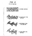
- Specifically, the following mixing ways are considered, as illustrated in
Fig. 6 ;
where the high-dispersion material is of fine particles, - (1) normal mixing;
where the main chain is an organic polymer, - (2) guest-host type mixing,
- (3) main chain type mixing, and
- (4) side chain type mixing.
- In the case of the film formation by vacuum vapor deposition, applicable methods include two-dimensional evaporation of the large-dispersion material and the low-index material, formation of equivalent layers by depositing the respective materials in units of several nm, and so on.
- However, as the units indicating high dispersion of polarizability become 2 nm or less to go into the molecular level, the environment of the high-dispersion units becomes far from the bulk state and tends to follow the Lorentz-Lorenz theory (Eq. (4)) with consideration to local electric fields, rather than the Drude theory. In this case, where the materials are mixed in fixed proportions, the dispersion tends to be lower, as compared with Eq. (3).

- Cx: weight concentration,
- nx: refractive index of bulk of each material,
- ρx: density in bulk of each material
- The blending materials can be either organic or inorganic materials if they are the material having large dispersion and the material indicating the property of low refractive index. There are no specific restrictions on the materials, but specific examples of the materials are the following materials. For the material with the low refractive index (nd ≤ 1.45), examples of the organic materials are amorphous fluororesins (nd = 1.28 to 1.38) represented by the following chemical formula, for example.

- There are no specific restrictions on the large-dispersion material (νd ≤ 25), but specific examples thereof are TiO2 (nd, νd = 2.2652, 11.8), Nb2O5 (nd, νd = 2.367, 14.0), ITO (nd, νd = 1.8581, 5.53), Cr2O3 (nd, νd = 2.2178, 13.4), BaTiO3 (nd, νd = 2.4362, 11.3), etc. and mixtures containing at least one of the forgoing materials.
- The optical material in the region of (nd ≤ -6.667 × 10⁻³νd + 1.70, νd ≤ 40) can be realized by using the low-index material of na ≤ 1.45 and particles of the large-dispersion material of νd ≤ 25 in the grain size of 2 to 100 nm.
- There are no specific restrictions on the low-index material, but it is desirably one of the amorphous fluororesins. The reason is that the amorphous fluororesins have low refractive indexes, are stable and less reactive, and give rise to less deviation from calculated values in the form of mixtures.
- There are no specific restrictions on the material with large dispersion (i.e., with a small Abbe's number), but it is desirably particles of a composite metal oxide of titanium and silicon (Six-Ti(1-x)O2). The ratio of metals can be adjusted to an arbitrary value for the composite metal oxide of titanium and silicon and it is thus easy to adjust the Abbe's number. The large-dispersion material used herein is the particles of the composite metal oxide of titanium and silicon adjusted to the Abbe's number (νd) of 24.5 ≤ 25.
- There are no specific restrictions on the grain size of the particles of the composite metal oxide of Ti and Si (Six-Ti(1-x)O2) as long as it does not cause unignorable scattering of light. The grain size is desirably not more than 100 nm.
- For uniformly dispersing the above particles of (Six-Ti(1-x)O2), for example, in the above amorphous fluororesins, it is effective to modify the surface of the particles of (Six-Ti(1-x)O2) by a fluorophilic group like the fluoroalkyl group.
- When the mixing ratio of the fluororesin and the composite metal oxide of (Six-Ti(1-x)O2) is in the range of 45:100 to 75:100, the resultant optical material is one satisfying the region {nd ≤ -6.667 × 10⁻³νd + 1.70, νd ≤ 40).
- As described above, the optical material in the region (nd ≤ -6.667 × 10⁻³νd + 1.70, νd ≤ 40) is obtained by mixing the material with the low index (nd ≤ 1.45) and the material with the large wavelength dispersion of refractive index (νd ≤ 25).
- In the present embodiment the low-index high-dispersion optical material is realized as described above.
- The aforementioned material, 2-ethoxy-ethyl methacrylate, is considered to be a material realizing (nd = 1.483, νd = 32) by decreasing the density in terms of the structure, but the structure of this 2-ethoxy-ethyl methacrylate is different from that of the optical material in the region (nd ≤ -6.667 × 10⁻³νd + 1.70, νd ≤ 40) prepared by forming the mixture of the material with the low index (nd ≤ 1.45) and the large-dispersion material (νd ≤ 25) in the present embodiment. In addition, the method with this 2-ethoxy-ethyl methacrylate provides less freedom for adjusting the levels of refractive index and wavelength dispersion than the method of the present embodiment.
- As another example, the optical material is realized in the region of (nd ≤ -0.01νd + 1.70, νd ≤ 40) by using the low-index material of nd ≤ 1.40 and particles with νd ≤ 15 and in the particle size of 2 to 100 nm as the large-dispersion material.
- There are no specific restrictions on the low-index material for realizing this optical material, but the low-index material is desirably one of the amorphous fluororesins. The reason is that the amorphous fluororesins have the low refractive indexes, are stable and less reactive, and thus give rise to less deviation from calculated values in the form of mixtures.
- There are no specific restrictions on the large-dispersion material for realizing the above optical material, but it is desirably particles of TiO2. The reason is that the TiO2 particles are relatively easily available and belong to the class of materials indicating the highest dispersion out of the particles for optical use commercially available commonly.
- There are no specific restrictions on the particle size of the TiO2 particles as long as it does not cause unignorable scattering of light. The particle size is preferably not more than 100 nm.
- For uniformly dispersing the above TiO2 particles, for example, in the aforementioned amorphous fluororesins, it is effective to modify the surface of the TiO2 particles by a fluorophilic group like the fluoroalkyl group.
- When the mixing ratio of the fluororesin and titanium oxide (TiO2) is in the range of 7:100 to 90:100, the optical material obtained satisfies the region (nd ≤ -6.667 × 10⁻³νd + 1.70, νd ≤ 40); when the ratio is in the range of 90:100 to 40:100, the optical material satisfies the region (nd ≤ -0.01νd + 1.70, νd ≤ 40).
- By mixing the low-index material (nd ≤ 1.40) with the large-dispersion material (νd ≤ 15) in this way, the optical material can be obtained in the region (nd ≤ -6.667 × 10⁻³νd + 1.70, νd ≤ 40) or in the region (nd ≤ -0.01νd + 1.70, νd ≤ 40).
- Among the materials such as TiO2 (nd, νd = 2.2652, 11.8), Nb2O5 (nd, νd = 2.367, 14.0), ITO (nd, νd = 1.8581, 5.53), Cr2O3 (nd, νd = 2.2178, 13.4), BaTiO3 (nd, νd = 2.4362, 11.3), etc. being large-dispersion materials, ITO (nd, νd = 1.8581, 5.53) has the Abbe's number (νd) of half or less those of the other high-dispersion materials and thus demonstrates extremely high dispersion.
- For that reason, as to ITO (nd, νd = 1.8581, 5.53), even if the low-index material is a material having the index of nd ≥ 1.45 but nd ≥ 1.55, the resultant optical material satisfies the region of (nd ≤ -6.667 × 10⁻³νd + 1.70, νd ≤ 40).
- The mixing material as the substance of nd ≤ 1.55 can be selected from the general-purpose optical materials as typified by polymethyl methacrylate (hereinafter referred to as PMMA; nd = 1.48), amorphous polyolefin (hereinafter referred to as APO; nd = 1.525), some of copolymers of methyl methacrylate and styrene (hereinafter referred to as MS; nd = 1.53 to 1.571), and so on.
- Since ITO is an electrically conductive substance, it can also reduce adhesion of dust to the lens surface due to charging specific to the optical resins for optical use.
- Since ITO shows absorption in the ultraviolet region, it acts as a UV absorber and thus relieves deterioration of the resin due to ultraviolet rays.
- The optical material in the region of (nd ≤ -6.667 × 10⁻³νd + 1.70, νd ≤ 40) can be realized by using the material of 1.45 ≤ nd ≤ 1.55 as the low-index material and using the particles having νd ≤ 10 and the particle size of 2 to 100 nm as the large-dispersion material.
- There are no specific restrictions on the low-index material for realizing this optical material, but it can be one of the general-purpose optical resins such as PMMA (nd = 1.48), APO (nd = 1.525), some of MS (nd = 1.533; the refractive index differs depending upon the copolymerization ratio of methyl methacrylate and styrene monomers), and so on.
- The high-dispersion material for realizing the above optical material is desirably ITO (nd, νd = 1.8581, 5.53). The reason is that there is no other material having the Abbe's number of not more than 10 in the visible region (light of 400 to 700 nm) than ITO (nd, νa = 1.8581, 5.53).
- There are no specific restrictions on the particle size of the particles of ITO (nd, νd = 1.8581, 5.53) as long as it does not affect the scattering of light. However, the particle size is desirably not more than 100 nm.
- For uniformly dispersing the above ITO particles, for example, in PMMA (nd = 1.48), APO (nd = 1.525), and some of MS (nd = 1.533) described above, it is effective to modify the surface of the ITO particles with an alkyl group having the nature of being compatible with PMMA.
- A low-index high-dispersion optical material satisfying the region (nd ≤ -6.667 × 10⁻³νd + 1.70, νd ≤ 40) can be obtained in either of the following cases:
where the mixing ratio of PMMA and ITO (nd, νd = 1.8581, 5.53) is in the range of 30:100 to 250:100; where the mixing ratio of APO (nd = 1.525) and ITO (nd, νd = 1.8581, 5.53) is in the range of 44:100 to 150:100; where the mixing ratio of MS (nd = 1.533) and ITO (nd, νd = 1.8581, 5.53) is in the range of 43:100 to 140:100. - Since ITO is the electroconductive material, the chargeability of the above optical materials is also reduced.
- The aforementioned material of 2-ethoxy-ethyl methacrylate is the material realizing (nd = 1.483, νd = 32) by decreasing the density in terms of the structure, but the structure thereof is different from the structure of the present optical materials in the range (nd ≤ -6.667 × 10⁻³νd + 1.70, νd ≤ 40) formed by mixing the low-index material (nd ≤ 1.55) with the large-dispersion material (νd ≤ 10). In addition, the method with 2-ethoxy-ethyl methacrylate provides less freedom for adjusting the levels of refractive index and index dispersion than the method of the present embodiment.
- Specific examples of the optical materials according to the present invention will be described below.
- The particles of Six-Ti(1-x)O2, the surface of which was modified with a fluorine surfactant according to [Method 1] described hereinafter and the refractive index and the index dispersion of which were adjusted to (nd, νd) = (1.703, 24.4), and the amorphous fluororesin (nd = 1.29) represented by the chemical formula below, were mixed at the weight ratios of Six-Ti(1-x)O2 : amorphous fluororesin = 18.3:100, 41.1:100, 70.5:100, and 88.5:100 in a fluorine solvent [the molecular structure of (C4F9)3N], which was a solvent in which the amorphous fluororesin was soluble.

- The refractive index and dispersion of the above mixture films were measured by a spectral ellipsometer (VASE: available from J. A. Woollam. Co., Inc.).
- The two-side (front side and back side) reflectance and transmittance of the above mixture films were measured by a spectrophotometer (U4000: available from Hitachi, Ltd.).
- Using measurements of the reflectance and transmittance of the above mixture films, absorption-scattering (rate) was calculated according to the equation below.

- The results of the refractive index and dispersion are presented in Table 1 and
Fig. 9 . - The mixtures at the ratios of Six-Ti(1-x)O2 : amorphous fluororesin = 18.3:100 and 41.1:100 had the refractive index and dispersion of (nd, νd) = (1.337, 53.9) and (1.383, 41.0), respectively, and were off the region of nd ≤ -6.667 × 10⁻³νd + 1.70, νd ≤ 40. However, since the absorption-scattering (rate) of the mixtures is not more than 0.01, they can be used as optical films without problems.
- The mixture at the ratio of Six-Ti(1-x)O2 : amorphous fluororesin = 70.5:100 had the refractive index and dispersion of (nd, νd) = (1.427, 34.9), and was present within the region of nd ≤ -6.667 × 10⁻³νd + 1.70, νd ≤ 40. The absorption-scattering (rate) thereof was not more than 0.01, and the mixture can be used as an optical film without problems.
- The mixture at the ratio of Six-Ti(1-x)O2 : amorphous fluororesin = 88.5:100 showed great scattering with the absorption-scattering (rate) of 0.04 and the refractive index and index dispersion thereof were unmeasurable.
- 4 g of a fluorine base surfactant, N-(3-(trimethoxysilyl) propyl)-N-propylperfluorooctanesulfonamide, was added to a solution containing 20 g of particles of Six-Ti(1-x)O2 (5 to 20 nm) in 500 g of 2, 2, 3, 3, 3-pentafluoro-1-propanol, and thereafter the mixture was put into 0.21 ml of IN hydrochloric acid. The mixture was agitated at 25°C for 24 hours to modify the surface of the particles. After that, 250 g of the fluorine solvent [the molecular structure of (C4F9)3N] was added to the mixture and fractional distillation was conducted at 90°C to remove the pentafluoro propanol and isopropanol etc. made by hydrolysis, thereby obtaining the fluorine solvent solution in which the particles of Six-Ti(1-x)O2 were dispersed.
- In contrast to Example 1, the particles of Six-Ti(1-x)O2 with the refractive index and dispersion of (nd, νd) = (1.636, 29.1) were used and the index dispersion of the high-dispersion material was νd > 25.
- The particles of Six-Ti(1-x)O2, the surface of which was modified with the fluorine surfactant according to [Method 1] described above and the refractive index and the index dispersion of which were adjusted to (nd, νd) = (1.636, 29.1), and the amorphous fluororesin (nd = 1.29) represented by the chemical formula below, were mixed at the weight ratios of Six-Ti(1-x)O2 : amorphous fluororesin = 17.3:100, 38.9:100, 66.7:100, and 83.8:100 in the fluorine solvent [the molecular structure of (C4F9)3N], which was a solvent in which the amorphous fluororesin was soluble.

- The refractive index and dispersion of the above mixture films were measured by the spectral ellipsometer (VASE: available from J. A. Woollam. Co., Inc.).
- The two-side reflectance and transmittance of the above mixture films were measured by the spectrophotometer (U4000: available from Hitachi, Ltd.).
- Using measurements of the reflectance and transmittance of the above mixture films, the absorption-scattering (rate) was calculated according to the equation below.

- The results of the refractive index and dispersion are presented in Table 1 and
Fig. 9 . - The mixture at the ratio of Six-Ti(1-x)O2 : amorphous fluororesin = 83.8:100 demonstrated large scattering with the absorption-scattering (rate) of 0.04 and the refractive index and index dispersion thereof were unmeasurable.
- The refractive index and index dispersion of the mixtures at the ratios of Six-Ti(1-x)O2 : amorphous fluororesin = 17.3:100, 38.9:100, and 66.7:100 were (nd, νd) = (1.329, 62.1), (1.366, 48.9), and (1.403, 42.1), respectively, and none of them existed in the region of nd ≤ -6.667 × 10⁻³νd + 1.70, νd ≤ 40.
- The present example was different from Example 1 in that the TiO2 particles with the refractive index and dispersion of (nd, νd) = (2.2652, 11.8) were used instead of the particles of Six-Ti(1-x)O2.
- The particles of TiO2, the surface of which was modified with the fluorine surfactant according to [Method 2] described hereinafter, and the amorphous fluororesin (nd = 1.29) represented by the chemical formula below, were mixed at the weight ratios of TiO2 : amorphous fluororesin = 4.5:100, 9.3:100, 19:100, 39:100, 74:100, and 120:100 in the fluorine solvent [the molecular structure of (C4F9)3N], which was the solvent in which the amorphous fluororesin was soluble.

- The refractive index and dispersion of the above mixture films were measured by the spectral ellipsometer (VASE: available from J. A. Woollam. Co., Inc.).
- The two-side reflectance and transmittance of the above mixture films were measured by the spectrophotometer (U4000: available from Hitachi, Ltd.).
- Using measurements of the reflectance and transmittance of the above mixture films, the absorption-scattering (rate) was calculated according to the equation below.

- The results of the refractive index and dispersion are presented in Table 2 and
Fig. 10 . - The mixture at the ratio of TiO2 : amorphous fluororesin = 4.5:100 had the refractive index and dispersion of (nd, νd) = (1.317, 48.3), and was off the region of nd ≤ -6.667 × 10⁻³vd + 1.70, νd ≤ 40. The mixture had the absorption-scattering (rate) of not more than 0.01 and thus can be used as an optical film without problems.
- The mixtures at the ratios of TiO2 : amorphous fluororesin = 9.3:100, 19:100, 39:100, and 74:100 had the refractive index and dispersion of (nd, νd) = (1.343, 34.2), (1.394, 23.8), (1.478, 17.8), and (1.591, 14.8), respectively, and were within the region of nd ≤ -6.667 × 10⁻³νd + 1.70, νd ≤ 40. They had the absorption-scattering (rates) of not more than 0.01 and can be used as optical films without problems.
- The mixture at the ratio of TiO2 : amorphous fluororesin = 120:100 demonstrated great scattering with the absorption-scattering (rate) of 0.06 and the refractive index and dispersion were unmeasurable.
- In this Example 2, when compared with Example 1, the region of nd ≤ -6.667 × 10⁻³νd + 1.70, νd ≤ 40 can be realized in the range of weight ratios of (TiO2 : amorphous fluororesin =) 7:100 to 90:100 and, further, the region of nd ≤ -0.01 × 10⁻³νd + 1.70, νd ≤ 40 is also realized thereby.
- 4 g of the fluorine base surfactant, N-(3-(trimethoxysilyl) propyl)-N-propylperfluorooctanesulfonamide, was added to a solution containing 20 g of TiO2 particles (5 to 20 nm) in 500 g of 2, 2, 3, 3, 3-pentafluoro-1-propanol and thereafter 0.21 ml of 1N hydrochloric acid was added thereto. The mixture was stirred at 25°C for 24 hours to modify the surface of the particles. After that, 250 g of the fluorine solvent [the molecular structure of (C4F9)3N] was added thereto and fractional distillation was conducted at 90°C to remove the pentafluoro propanol, and isopropanol etc. created by hydrolysis, thereby preparing the fluorine solvent solution in which the TiO2 particles were dispersed.
- Comparative Example 2 was different from Example 2 in that a polymer with the refractive index (nd = 1.52) was used instead of the amorphous fluororesin (nd = 1.29).
- The TiO2 particles and PVA (nd = 1.52) were blended at the weight ratios of TiO2 : PVA = 2 to 200:100 in a solution (water : MeOH = 1:1). The percentage of PVA to the solvent was 4%. A coating of each of the above solutions was formed on the substrate of BK7 of Φ49 × 2t by the dip coat method and thereafter it was heated in the furnace at 180°C for 20 minutes, thereby obtaining a mixture film of PVA and the TiO2 particles.
- The refractive index and dispersion of the above mixture films were measured by the spectral ellipsometer (VASE: available from J. A. Woollam. Co., Inc.).
- The two-side reflectance and transmittance of the above mixture films were measured by the spectrophotometer (U4000: available from Hitachi, Ltd.).
- Using measurements of the reflectance and transmittance of the above mixture films, the absorption-scattering (rate) was calculated according to the equation below.

- The results of the refractive index and dispersion are presented in Table 3 and
Fig. 11 . - The refractive index and dispersion of the mixtures were (nd, νd) = (1.564, 33.0), (1.590, 23.9), (1.633, 18.1), and (1.691, 15.2), neither of which was present in the region of nd ≤ -6.667 × 10⁻³νd + 1.70, νd ≤ 40.
- The optical material adjusted to (nd, νd) = (1.523, 16.4) by mixing the amorphous fluororesin (nd = 1.29) represented by the chemical formula below and the TiO2 particles at the weight ratio of TiO2 : amorphous fluororesin = 51:100 as described in Example 2 was combined with PSK50: (nd, νd) = (1.5938, 60.9) available from Sumita Kogaku Kogyo, in the structure illustrated in
Fig. 7 .
- p-methoxybenzyl methacrylate: (nd, νd) = (1.552, 32.5), which was a material used heretofore, was combined with PSK50: (nd, νd) = (1.5938, 60.9). The height d of the grating was 15 µm and the diffraction efficiency was not less than 98% for the light at the wavelengths in the visible region of 400 to 700 nm.
- Particles of ITO (nd, νd = 1.8581, 5.53), the surface of which was modified with an alkyl group for enhancing the compatibility with PMMA according to [Method 3] described hereinafter, and PMMA (nd = 1.48) were mixed at the weight ratios of ITO : PMMA = 20:100, 30:100, 50:100, 120:100, 200:100, and 300:100 in methyl ethyl ketone (hereinafter referred to as MEK), which was a solvent in which PMMA was soluble. The percentage of PMMA to the solvent was 4%. A coating of each of the above solutions was formed on the substrate of BK7 of Φ49 × 2t by the dip coat method and thereafter heated in the furnace at 80°C for 20 minutes, thereby obtaining a mixture film of PMMA and ITO particles.
- The refractive index and dispersion of the above mixture films were measured by the spectral ellipsometer (VASE: available from J. A. Woollam. Co., Inc.).
- The two-side reflectance and transmittance of the above mixture films were measured by the spectrophotometer (U4000: available from Hitachi, Ltd.).
- Using measurements of the reflectance and transmittance of the above mixture films, the absorption-scattering (rate) was calculated according to the equation below.

- The results of the refractive index and dispersion are presented in Table 4 and
Fig. 12 . - The mixture at the weight ratio of ITO : PMMA = 20:100 demonstrated the refractive index and dispersion of (nd, νd) = (1.507, 32), and was off the region of nd ≤ -6.667 × 10⁻³νd + 1.70, νd ≤ 40.
- The mixture had the absorption-scattering (rate) of not more than 0.01 and thus can be used as an optical film without problems.
- The mixtures at the weight ratios of ITO : PMMA = 30:100, 50:100, 120:100, and 200:100 had the refractive index and dispersion of (nd, νd) = (1.515, 26.6), (1.531, 20.1), (1.571, 13.2), and (1.609, 10.2), respectively, and were in the region of nd ≤ -6.667 x 10⁻³νd + 1.70, νd ≤ 40.
- The mixtures had the absorption-scattering (rates) of not more than 0.01 and thus can be used as optical films without problems.
- The mixture at the weight ratio of ITO : PMMA = 300:100 had the refractive index and dispersion of (nd, νd) = (1.647, 8.6), and was off the region of nd ≤ -6.667 × 10⁻³νd + 1.70, νd ≤ 40.
- The chargeability was measured with an electrostatic voltmeter after each sample was wiped twenty times with wiping fabric (Savina Minimax: available from Kanebo Gosen K.K.). PMMA alone demonstrated the chargeability of 3 kV but the mixtures all showed no charge.
- 4 g of γ-methacryloxypropyltrimethoxysilane was added into a solution containing 20 g of ITO particles (5 to 20 nm) in 500 g of MEK and thereafter 0.2 ml of IN hydrochloric acid was added thereto. The mixture was stirred at 25°C for 24 hours to modify the surface of the particles.
- Comparative Example 4 was different from Example 4 in that the particles of TiO2 (nd, νd = 2.2652, 11.8) were used and the index dispersion of the high-dispersion material was νd > 10.
- The TiO2 particles (nd = 1.29), the surface of which was modified with an alkyl group for enhancing the compatibility with PMMA according to [Method 4] described hereinafter, and PMMA were mixed at the weight ratios of TiO2 : PMMA = 20:100, 50:100, 85:100, and 160:100 in MEK, which was a solvent in which PMMA was soluble. The percentage of PMMA to the solvent was 4%. A coating of each of the above solutions was formed on the substrate of BK7 of Φ49 × 2t by the dip coat method and thereafter was heated in the furnace at 80°C for 20 minutes, thereby obtaining a mixture film of PMMA and TiO2 particles.
- The two-side reflectance and transmittance of the above mixture films were measured by the spectrophotometer (U4000: available from Hitachi, Ltd.).
- Using measurements of the reflectance and transmittance of the above mixture films, the absorption-scattering (rate) was calculated according to the equation below.

- The results of the refractive index and dispersion are presented in Table 4 and
Fig. 12 . - The mixtures at the weight ratios of TiO2 : PMMA = 20:100, 50:100, 85:100, and 160:100 had the refractive index and dispersion of (nd, νd) = (1.519, 40.2), (1.585, 26), (1.63, 21.7), and (1.717, 17.5), respectively, and were off the region of nd ≤ -6.667 × 10⁻³νd + 1.70, νd ≤ 40.
- The chargeability was measured with the electrostatic voltmeter after each sample was wiped twenty times with the wiping fabric (Savina Minimax: available from Kanebo Gosen K.K.). PMMA alone demonstrated the chargeability of 3 kV. The mixtures showed the chargeability of 1 kV to 2 kV.
- 4 g of γ-methacryloxypropyltrimethoxysilane was added to a solution containing 20 g of TiO2 particles (5 to 20 nm) in 500 g of MEK, and thereafter 0.2 ml of IN hydrochloric acid was added thereto. The mixture was stirred at 25°C for 24 hours to modify the surface of the particles.
- Comparative Example 5 was different from Example 4 in that polycarbonate (hereinafter referred to as PC) with the refractive index (nd = 1.59) was used instead of PMMA (nd = 1.48).
- The ITO particles and PC (nd = 1.59) were mixed at the weight ratios of ITO : PC = 20:100, 50:100, 85:100, and 160:100 in dichloroethane. The percentage of the solute to the solvent of dichloroethane was 4%. A coating of each of the above solutions was formed on the substrate of BK7 of Φ49 × 2t by the dip coat method and thereafter was heated in the furnace at 110°C for 20 minutes, thereby obtaining a mixture film of PC and ITO particles.
- The refractive index and dispersion of the above mixture films were measured by the spectral ellipsometer (VASE: available from J. A. Woollam. Co., Inc.).
- The two-side reflectance and transmittance of the above mixture films were measured by the spectrophotometer (U4000: available from Hitachi, Ltd.).
- Using measurements of the reflectance and transmittance of the above mixture films, the absorption-scattering (rate) was calculated according to the equation below.

- The results of the refractive index and dispersion are presented in Table 4 and
Fig. 12 . - The mixtures had the refractive index and dispersion of (nd, νd) = (1.596, 23.2), (1.614, 17.5), (1.628, 14.7), and (1.657, 11.4), respectively, and all were off the region of nd ≤ -6.667 × 10⁻³νd + 1.70, νd ≤ 40.
- The chargeability was measured with the electrostatic voltmeter after each sample was wiped twenty times with the wiping fabric (Savina Minimax: available from Kanebo Gosen K.K.). PC alone demonstrated the chargeability of 3 kV, but the mixtures all showed no charge.
- The particles of ITO (nd, νd = 1.8581, 5.53), the surface of which was modified with an alkyl group for enhancing the compatibility with APO (nd = 1.525) according to [Method 5] described hereinafter, and APO (nd = 1.525) were mixed at the weight ratios of ITO : APO = 25:100, 45:100, 70:100, 100:100, 135:100, and 220:100 in xylene, which was a solvent in which APO was soluble. The percentage of APO to the solvent was 4%. A coating of each of the above solutions was formed on the substrate of BK7 of Φ49 × 2t by the dip coat method and thereafter was heated in the furnace at 110°C for 20 minutes, thereby obtaining a mixture film of APO and ITO particles.
- The refractive index and dispersion of the above mixture films were measured by the spectral ellipsometer (VASE: available from J. A. Woollam. Co., Inc.).
- The two-side reflectance and transmittance of the above mixture films were measured by the spectrophotometer (U4000: available from Hitachi, Ltd.).
- Using measurements of the reflectance and transmittance of the above mixture films, the absorption-scattering (rate) was calculated according to the equation below.

- The results of the refractive index and dispersion are presented in Table 5 and
Fig. 13 . - The mixture at the weight ratio of ITO : APO = 25:100 had the refractive index and dispersion of (nd, νd) = (1.548, 26.6), and was off the region of nd ≤ -6.667 × 10⁻³νd + 1.70, νd ≤ 40.
- The mixture had the absorption-scattering (rate) of not more than 0.01 and can be used as an optical film without problems.
- The mixtures at the weight ratios of ITO : APO = 45:100, 70:100, 100:100, and 135:100 had the refractive index and dispersion of (nd, νd) = (1.562, 20.5), (1.580, 16.2), (1.598, 13.6), and (1.615, 11.8), respectively, and they were in the region of nd ≤ -6.667 × 10⁻³νd + 1.70, νd ≤ 40.
- The mixtures had the absorption-scattering (rates) of not more than 0.01 and can be used as optical films without problems.
- The mixture at the weight ratio of ITO : APO = 220:100 had the refractive index and dispersion of (nd, νd) = (1.650, 9.63), and was off the region of nd ≤ 6.667 × 10⁻³νd + 1.70, νd ≤ 40.
- The chargeability was measured with the electrostatic voltmeter after each sample was wiped twenty times with the wiping fabric (Savina Minimax: available from Kanebo Gosen K.K.). APO alone demonstrated the chargeability of 3 kV, but the mixtures all showed no charge.
- 4 g of β-(3, 4 epoxycyclohexyl) ethyltrimethoxysilane was added to a solution containing 20 g of ITO particles (5 to 20 nm) in 500 g of n-butanol, and thereafter 0.2 ml of 1N hydrochloric acid was added thereto. The mixture was stirred at 25°C for 24 hours to modify the surface of the particles.
- After that, 250 g of xylene was added to the solution and n-butanol was removed by distillation to obtain a xylene solution of ITO particles.
- The surface of particles of ITO (nd, νd = 1.8581, 5.53) was modified with an alkyl group for enhancing the compatibility with MS (nd = 1.534) according to [Method 3].
- The ITO particles and MS (nd = 1.534) were mixed at the weight ratios of ITO : MS = 25:100, 45:100, 70:100, 100:100, 135:100, and 220:100 in MEK which was a solvent in which MS was soluble. The percentage of MS to the solvent was 4%. A coating of each of the above solutions was formed on the substrate of BK7 of Φ49 × 2t by the dip coat method and thereafter was heated in the furnace at 80°C for 20 minutes, thereby obtaining a mixture film of MS and ITO particles.
- The refractive index and dispersion of the above mixture films were measured by the spectral ellipsometer (VASE: available from J. A. Woollam. Co., Inc.).
- The two-side reflectance and transmittance of the above mixture films were measured by the spectrophotometer (U4000: available from Hitachi, Ltd.).
- Using measurements of the reflectance and transmittance of the above mixture films, the absorption-scattering (rate) was calculated according to the equation below.

- The results of the refractive index and dispersion are presented in Table 5 and
Fig. 13 . - The mixture at the weight ratio of ITO : MS = 25:100 had the refractive index and dispersion of (nd, vd) = (1.555, 24.1), and was off the region of nd -6.667 × 10⁻³νd + 1.70, νd ≤ 40.
- The mixture had the absorption-scattering (rate) of not more than 0.01 and can be used as an optical film without problems.
- The mixtures at the weight ratios of ITO : MS = 45:100, 70:100, 100:100, and 135:100 had the refractive index and dispersion of (nd, νd) = (1.569, 19.2), (1.587, 15.5), (1.604, 13.2), and (1.621, 11.6), respectively, and they were in the region of nd ≤ -6.667 × 10⁻³νd + 1.70, νd ≤ 40.
- The mixtures had the absorption-scattering (rates) of not more than 0.01 and can be used as optical films without problems.
- The mixture at the weight ratio of ITO : MS = 220:100 had the refractive index and dispersion of (nd, νd) = (1.655, 9.51), and was off the region of nd ≤ -6.667 × 10⁻³νd + 1.70, νd ≤ 40.
- The chargeability was measured with the electrostatic voltmeter after each sample was wiped twenty times with the wiping fabric (Savina Minimax: available from Kanebo Gosen K.K.). PC alone demonstrated the chargeability of 3 kV, but the mixtures all showed no charge.
- The optical material adjusted to (nd, νd) = (1.531, 20.1) by mixing PMMA and ITO particles at the weight ratio of ITO : PMMA = 50:100 as described in Example 4, was combined with PSK50: (nd, νd) = (1.5938, 60.9) available from Sumita Kogaku Kogyo, in the structure illustrated in
Fig. 8 . The height d of the grating was 9.98 µm and the diffraction efficiency was not less than 98% for the light at the wavelengths in the visible region of 400 to 700 nm. - The height of the grating was approximately two thirds of that in Comparative Example 3 and this is advantageous in terms of forming of lens.
- The chargeability was measured with the electrostatic voltmeter after the sample was wiped twenty times with the wiping fabric (Savina Minimax: available from Kanebo Gosen K.K.). The sample showed no charge.
- The conventional material of p-methoxybenzyl methacrylate: (nd, νd) = (1.552, 32.5) was combined with PSK50: (nd, νd) = (1.5938, 60.9). The height d of the grating was 15 µm and the diffraction efficiency was not less than 98% for the light at the wavelengths in the visible region of 400 to 700 nm.
- The chargeability was measured with the electrostatic voltmeter after the sample was wiped twenty times with the wiping fabric (Savina Minimax: available from Kanebo Gosen K.K.). The sample showed the charge of 1 kV.
- Example 8 is different from Example 1 in that the TiO2 particles with the refractive index and dispersion of (nd, νd = 2.2652, 11.8) were used instead of the particles of Six-TiO2 and the dimethylsilicone resin was used instead of the amorphous fluororesin.
- The TiO2 particles, the surface of which was modified with a functional group of dimethylsilicone according to [Method 6] described hereinafter, and the elastomer of dimethylsilicone resin (nd = 1.43) were mixed at the weight ratios of TiO2 : dimethylsilicone resin = 5:100, 10:100, 20:100, 38:100, 55:100, and 88:100 in n-heptane, which was a solvent in which the elastomer of dimethylsilicone was soluble.
- The percentage of the dimethylsilicone resin to the solvent was 4%. A coating of each of the above solutions was formed on the substrate of BK7 of Φ49 × 2t by the dip coat method and thereafter was heated in the furnace at 150°C for 20 minutes, thereby obtaining a mixture film of the dimethylsilicone resin and the TiO2 particles.
- The refractive index and dispersion of the above mixture films were measured by the spectral ellipsometer (VASE: available from J. A. Woollam. Co., Inc.).
- The two-side reflectance and transmittance of the above mixture films were measured by the spectrophotometer (U4000: available from Hitachi, Ltd.).
- Using measurements of the reflectance and transmittance of the above mixture films, the absorption-scattering (rate) was calculated according to the equation below.

- The results of the refractive index and dispersion are presented in Table 6 and
Fig. 14 . - The mixtures at the weight ratios of TiO2 : dimethylsilicone resin = 5:100 and 10:100 had the refractive index and dispersion of (nd, νd) = (1.4395, 44.6) and (1.4501, 39.9), respectively, and were off the region of nd ≤ -6.667 × 10⁻³νd + 1.70, νd ≤ 40.
- The mixtures had the absorption-scattering (rates) of not more than 0.01 and can be used as optical films without problems.
- The mixtures at the weight ratios of TiO2 : dimethylsilicone resin = 20:100, 38:100, and 55:100 had the refractive index and dispersion of (nd, νd) = (1.4713, 33.5), (1.5024, 27.7), and (1.5329, 24.2), respectively, and were within the region of nd ≤ -6.667 × 10⁻³νd + 1.70, νd ≤ 40.
- The mixtures had the absorption-scattering (rates) of not more than 0.01 and can be used as optical films without problems.
- The mixture at the weight ratio of TiO2 : dimethylsilicone resin = 88:100 had the refractive index and dispersion of (nd, νd) = (1.5824, 20.6), and was off the region of nd ≤ -6.667 × 10⁻³νd + 1.70, νd ≤ 40.
- The mixture had the absorption-scattering (rate) of 0.02.
- In this Example 8, the region of nd ≤ -6.667 × 10⁻³νd + 1.70, νd ≤ 40 was able to be achieved similarly in the weight ratio range of (TiO2 : dimethylsilicone resin =) 18:100 to 70:100 by use of the material with the small Abbe's number like the TiO2 particles of (nd, νd) = (2.2652, 11.8) though the refractive index of the polymer as a host had the refractive index of nd = 1.43 larger than that in Example 1.
- 4 g of the silicone base surfactant was added to a solution containing 20 g of TiO2 particles (5 to 20 nm) in 500 g of n-butanol, and thereafter 0.2 ml of 1N hydrochloric acid was added thereto. The solution was stirred at 25°C for 24 hours to modify the surface of the particles.
- After that, 250 g of n-heptane was added to the solution and the fractional distillation was conducted at 100°C to remove n-butanol, and alcohols etc. created by hydrolysis, thereby preparing the n-heptane solution in which the TiO2 particles were dispersed.
- The optical materials prepared according to the above method of the present embodiment are used for the optical systems such as image pickup optical systems, projection optical systems, illumination systems, and so on, or for the optical devices such as cameras, microscopes, binoculars, and so on.
- Each of the above examples permits attainment of the optical materials satisfying the region (nd ≤ -6.667 × 10⁻³νd + 1.70, νd ≤ 40) or nd ≤ -0.01νd + 1.70, νd ≤ 40 and being indispensable for performance enhancement of the refracting optical systems and stack optical elements, and the optical systems using it.
- Particularly, the optical material satisfying the low-index high-dispersion region (nd ≤ -6.667 × 10⁻³νd + 1.70, νd ≤ 40) can be realized by mixing the low-index material (nd ≤ 1.45) with the large-dispersion material (νd ≤ 25) as described above.
- In that case, the optical material can be one better satisfying the region (nd ≤ -6.667 × 10⁻³νd + 1.70, νd ≤ 40) where the particles (2 to 100 nm) of the composite metal oxide of titanium and silicon (Six-Ti(1-x)O2) (νd = 24.4) are used as the large-dispersion material, the amorphous fluororesin (nd = 1.29 to 1.38) is used as the low-index material, and they are mixed in the weight ratio range of (Six-Ti(1-x)O2 fluororesin) of 45:100 to 75:100.
- Further, the low-index high-dispersion region (nd ≤ -0.01νd + 1.70, νd ≤ 40) can be realized by mixing the low-index material (nd ≤ 1.40) with the particles of the large-dispersion material (νd ≤ 15).
- In that case, the low index and high dispersion tendency is enhanced more where the particles (2 to 100 nm) of TiO2 (nd, νd = 2.2652, 11.8) are used as the large-dispersion material, the amorphous fluororesin (nd = 1.29 to 1.38) as the low-index material, and they are mixed in the weight ratio range of (TiO2 : fluororesin) of 7:100 to 90:100.
- This permits the supply of the optical materials in the region (nd ≤ -6.667 × 10⁻³νd + 1.70, νd ≤ 40) and in the region ( nd ≤ -0.01νd + 1.70, νd ≤ 40) and thus facilitates achievement of higher performance of the optical systems such as the refracting optical systems, the stack optical elements, and so on.
- The low-index high-dispersion region (nd ≤ -6.667 × 10⁻³νd + 1.70, νd ≤ 40) can also be realized by mixing the low-index material (1.45 ≤ nd ≤ 1.55) with the large-dispersion material (νd ≤ 10) as described above.
- In that case, the optical material can be one better satisfying the region (nd ≤ -6.667 × 10⁻³νd + 1.70, νd ≤ 40) where the particles (2 to 100 nm) of ITO (νd = 5.53) are used as the large-dispersion material, either polymethyl methacrylate (PMMA, nd = 1.48), amorphous polyolefin (APO, nd = 1.525), or the copolymer of methyl methacrylate and styrene (MS, nd = 1.533) as the low-index material, and they are mixed in the weight ratio range of (ITO : PMMA) of 30:100 to 250:100, in the weight ratio range of (ITO : APO) of 44:100 to 150:100, or in the weight ratio range of (ITO : MS) of 43:100 to 140:100.
- This permits the supply of the optical materials in the region (nd ≤ -6.667 × 10⁻³νd + 1.70, νd ≤ 40) by use of the materials of 1.45 ≤ nd ≤ 1.55 such as PMMA (nd = 1.48), APO (nd = 1.525), MS (nd = 1.533), etc. which are commonly used as optical materials, and thus facilitates achievement of higher performance of the refracting optical systems and stack diffracting optical elements.
- At the same time, since ITO is the electroconductive substance, it can reduce the chargeability of the above optical resin materials and thus can suppress decrease of transmitted light and increase of scattered light in the optical systems due to attachment of dust or the like.
Table 1 Refractive Index and Abbe's Number of SiO2-TiO2 (nd, vd) Weight Ratio (Six-Ti(1-x)O2: TefronAF) Refractive Index nd Abbe's Number vd Absorption / Scattering (λ=500nm) = 1 - (Transmittance) - (Two-side Reflectance) Example 1 1.703, 24.4 18.3 : 100 1.337 53.9 less than 0.005 41.1 :100 1.383 41.0 less than 0.005 70.5 . 100 1.427 34.9 less than 0.005 88.5:100 ----- ----- 0.04 Comparative Example 1 1.636, 29.1 17.3 : 100 1.329 62.1 less than 0.005 38.9 : 100 1.366 48.9 less than 0.005 66.7 : 100 1.403 42.1 less than 0.005 83.8:100 ----- ----- 0.04 Table 2 Weight Ratio (TiO2 : TefronAF) Refractive Index nd Abbe's Number vd Absorption / Scattering (λ=500nm) = 1 -(Transmittance) - (Two-side Reflectance) Example 2 4.5 : 100 1.317 48.3 less than 0.005 9.3 : 100 1.343 34.2 less than 0.005 19 . 100 1.394 23.8 less than 0.005 39 : 100 1.478 17.8 less than 0.005 74 : 100 1.591 14.8 0.007 120:100 ----- ----- 0.06 Table 3 Weight Ratio (TiO2 : Polymer) Refractive Index nd Abbe's Number vd Absorption / Scattering (λ=500nm) = 1 -(Transmittance) - (Two-side Reflectance) Comparative Example 2 14.8 : 100 1.564 33.0 less than 0.005 29.6 100 1.590 23.9 less than 0.005 59.3 : 100 1.633 18.1 less than 0.005 103.7: 100 1.691 15.2 0.007 Table 4 High Disperse Material and Low Refraction Material, and their Index and Abbe's Number (nd, vd) Weight Ratio (High Disperse Material . Low Refraction Material) Refractive Index nd Abbe's Number vd Absorption / Scattering (λ=500nm) = 1 - (Transmittance) - (Two-side Reflectance) Example 4 ITO
(nd, vd = 1.8581, 5.53)
PMMA
(nd, vd = 1.490, 57.6)20 : 100 1.5065 32.1 less than 0.005 30 : 100 1.5146 26.6 less than 0.005 50 : 100 1.5308 20.1 less than 0.005 120 : 100 1.5705 13.2 less than 0.005 200 : 100 1.6093 10.2 less than 0.005 300 : 100 1.6471 8.65 0.01 Comparative Example 4 TiO2
(Nd, Vd = 2.265, 11.8)
PMMA
(Nd, Vd = 1.490, 57.6)20 : 100 1.5190 40.2 less than 0.005 50 : 100 1.5847 25.9 less than 0.005 85 : 100 1.6300 21.7 less than 0.005 160 : 100 1.7169 17.5 less than 0.005 Comparative Example 5 ITO
(Nd, Vd = 1.8581, 5.53)
PC
(Nd, Vd = 1.58, 30.5)20 : 100 1.5961 23.2 less than 0.005 50 : 100 1.6137 17.5 less than 0.005 85 : 100 1.6282 14.7 less than 0.005 160 : 100 1.6569 11.4 less than 0.005 Table 5 High Disperse Material and Low Refraction Material, and their Index and Abbe's Number (nd, vd) Weight Ratio (High Disperse Material : Low Refraction Material) Refractive Index nd Abbe's Number vd Absorption / Scattering (λ=500nm) = 1 - (Transmittance) - (Two-side Reflectance) Example 5 ITO
(nd, Vd = 1.8581, 5.53)
APO
(nd, vd = 1.525, 52.1)25 : 100 1.548 26.6 less than 0.005 45 : 100 1.562 20.5 less than 0.005 70 : 100 1.580 16.2 less than 0.005 100 : 100 1.598 13.6 less than 0.005 135 : 100 1.615 1 1.8 less than 0.005 220 : 100 1.650 9.63 0.01 Example 6 ITO
(Nd, vd = 1.8581, 5.53)
MS
(Nd, vd = 1.534, 41.5)25 : 100 1.555 24.1 less than 0.005 45 : 100 1.569 19.2 less than 0.005 70 : 100 1.587 15.5 less than 0.005 100 : 100 1.604 13.2 less than 0.005 135 : 100 1.621 11.6 less than 0.005 220 : 100 1.655 9.51 0.01 Table 6 Weight Ratio (TiO2 : Dimethyl Silicone) Refractive Index nd Abbe's Number vd Absorption / Scattering (λ=500nm) = 1 -(Transmittance) - (Two-side Reflectance) Example 8 5 : 100 1.440 44.6 less than 0.005 10 : 100 1.450 39.9 less than 0.005 20 : 100 1.471 33.5 less than 0.005 38 : 100 1.502 27.7 less than 0.005 55 : 100 1.533 24.2 less than 0.005 88 : 100 1.582 20.6 0.02
Claims (18)
- A method for producing a low refractive index high dispersion optical material wherein the relation between the refractive index for the d-line (nd) and the Abbe number (νd) of said optical material is defined as follows:

- A method according to claim 1 wherein said Abbe number (νd) of said optical material is less than 40.
- A method according to claim 1 or claim 2 wherein said second material comprises particles having a grain size in the range of 2 to 100 nm.
- A method according to any preceding claim wherein said first material is an amorphous fluororesin.
- A method according to any preceding claim wherein said second material is particles of a composite metal oxide of titanium and silicon (Six-Ti(1-x)O2) having an Abbe number (νd) of 24.4.
- A method according to any preceding claim wherein said first material is an amorphous fluororesin, said second material is particles of a composite metal oxide of titanium and silicon (Six-Ti(1-x)O2) having an Abbe number (νd) of 24.4, and the weight ratio of the particles and said amorphous fluororesin is in the range of 45:100 to 75:100.
- A method according to any one of claims 1 to 3 wherein said first material is a dimethylsilicone resin.
- A method according to any one of claims 1 to 3 and claim 7 wherein said second material comprises particles of titanium oxide (TiO2).
- A method according to any one of claims 1 to 3 wherein said first material is a dimethylsilicone resin, said second material is particles of titanium oxide (TiO2), and the weight ratio of the titanium oxide and said dimethylsilicone resin is in the range of 18:100 to 70:100.
- A low refractive index high dispersion optical material wherein the relation between the refractive index for the d-line (nd) and the Abbe number (νd) of said optical material is defined as follows:

- A material according to claim 10 wherein said Abbe number (νd) of said optical material is less than 40.
- A material according to claim 10 or claim 11 wherein said second material comprises particles having a grain size in the range of 2 to 100 nm.
- A material according to any one of claims 10 to 12 wherein said first material is an amorphous fluororesin.
- A material according to any one of claims 10 to 13 wherein said second material is particles of a composite metal oxide of titanium and silicon (Six-Ti(1-x)O2) having an Abbe number (νd) of 24.4.
- A material according to any one of claims 10 to 14 wherein said first material is an amorphous fluororesin, said second material is particles of a composite metal oxide of titanium and silicon (Six-Ti(1-x)O2) having an Abbe number (νd) of 24.4, and the weight ratio of the particles and said amorphous fluororesin is in the range of 45:100 to 75:100.
- A material according to any one of claims 10 to 12 wherein said first material is a dimethylsilicone resin.
- A material according to any one of claims 10 to 12 and claim 16 wherein said second material comprises particles of titanium oxide (TiO2).
- A material according to any one of claims 10 to 12 wherein said first material is a dimethylsilicone resin, said second material is particles of titanium oxide (TiO2), and the weight ratio of the titanium oxide and said dimethylsilicone resin is in the range of 18:100 to 70:100.
Applications Claiming Priority (4)
| Application Number | Priority Date | Filing Date | Title |
|---|---|---|---|
| JP18767899 | 1999-07-01 | ||
| JP18767899 | 1999-07-01 | ||
| JP2000042600 | 2000-02-21 | ||
| JP2000042600A JP3517625B2 (en) | 1999-07-01 | 2000-02-21 | Optical material and optical system using the same |
Publications (3)
| Publication Number | Publication Date |
|---|---|
| EP1065531A2 EP1065531A2 (en) | 2001-01-03 |
| EP1065531A3 EP1065531A3 (en) | 2002-01-09 |
| EP1065531B1 true EP1065531B1 (en) | 2008-12-24 |
Family
ID=26504503
Family Applications (1)
| Application Number | Title | Priority Date | Filing Date |
|---|---|---|---|
| EP00305499A Expired - Lifetime EP1065531B1 (en) | 1999-07-01 | 2000-06-30 | Low refractive index high dispersion optical material and method of production |
Country Status (4)
| Country | Link |
|---|---|
| US (2) | US6759471B1 (en) |
| EP (1) | EP1065531B1 (en) |
| JP (1) | JP3517625B2 (en) |
| DE (1) | DE60041165D1 (en) |
Families Citing this family (36)
| Publication number | Priority date | Publication date | Assignee | Title |
|---|---|---|---|---|
| JP3517625B2 (en) * | 1999-07-01 | 2004-04-12 | キヤノン株式会社 | Optical material and optical system using the same |
| JP4217032B2 (en) * | 2002-06-17 | 2009-01-28 | オリンパス株式会社 | Optical element |
| EP1376161B1 (en) * | 2002-06-17 | 2008-10-15 | Canon Kabushiki Kaisha | Diffractive optical element and optical system provided with the same |
| JP4411026B2 (en) * | 2002-08-30 | 2010-02-10 | キヤノン株式会社 | Optical material, optical element, diffractive optical element, laminated diffractive optical element, optical system |
| JP4266732B2 (en) * | 2002-08-30 | 2009-05-20 | キヤノン株式会社 | Multilayer diffractive optical element |
| JP4579553B2 (en) * | 2004-01-30 | 2010-11-10 | キヤノン株式会社 | Optical system and optical apparatus having the same |
| JP4636812B2 (en) * | 2004-04-28 | 2011-02-23 | キヤノン株式会社 | Zoom lens |
| JP4817705B2 (en) * | 2004-04-28 | 2011-11-16 | キヤノン株式会社 | Optical system |
| US7116497B2 (en) | 2004-04-28 | 2006-10-03 | Canon Kabushiki Kaisha | Retrofocus type optical system |
| JP4630568B2 (en) * | 2004-04-28 | 2011-02-09 | キヤノン株式会社 | Optical system and optical apparatus having the same |
| JP4612810B2 (en) | 2004-06-11 | 2011-01-12 | キヤノン株式会社 | Optical system |
| JP4745707B2 (en) * | 2005-04-22 | 2011-08-10 | キヤノン株式会社 | Optical system |
| JP4756901B2 (en) * | 2005-04-25 | 2011-08-24 | キヤノン株式会社 | Eyepiece lens and optical instrument using the same |
| JP4810133B2 (en) * | 2005-06-15 | 2011-11-09 | キヤノン株式会社 | Zoom lens and imaging apparatus having the same |
| CN101995594A (en) * | 2005-08-29 | 2011-03-30 | 松下电器产业株式会社 | Diffractive optical element and method for manufacturing the same, and imaging apparatus using the diffractive optical element |
| CN101300286B (en) * | 2005-11-10 | 2011-03-30 | 帝人化成株式会社 | Optical device and achromatic lens |
| EP1978380A4 (en) * | 2006-01-27 | 2014-07-09 | Asahi Glass Co Ltd | Fluoropolymer for chromatic aberration correction lens, and chromatic aberration correction lens |
| US8154803B2 (en) * | 2006-04-13 | 2012-04-10 | Panasonic Corporation | Diffractive optical element with improved light transmittance |
| JP4847351B2 (en) * | 2007-01-11 | 2011-12-28 | キヤノン株式会社 | Diffractive optical element and diffraction grating using the same |
| EP1947488B1 (en) | 2007-01-22 | 2010-05-12 | Canon Kabushiki Kaisha | Laminated diffraction optical element |
| WO2008099460A1 (en) * | 2007-02-13 | 2008-08-21 | Konica Minolta Opto, Inc. | Optical resin material and optical element |
| JP5167724B2 (en) * | 2007-08-21 | 2013-03-21 | 株式会社ニコン | Optical system |
| JP5132284B2 (en) * | 2007-12-03 | 2013-01-30 | キヤノン株式会社 | Diffractive optical element, optical system having the same, and optical instrument |
| JP5424623B2 (en) * | 2008-01-21 | 2014-02-26 | キヤノン株式会社 | Resin composition and optical element, diffractive optical element and laminated diffractive optical element molded thereby |
| JP2009276726A (en) * | 2008-04-17 | 2009-11-26 | Olympus Corp | Optical material composition and optical element using the same |
| JP5618510B2 (en) * | 2008-09-22 | 2014-11-05 | キヤノン株式会社 | Optical material and optical element |
| JP5590851B2 (en) * | 2008-12-10 | 2014-09-17 | キヤノン株式会社 | Diffractive optical element, laminated diffractive optical element and method of manufacturing the same |
| JP5583210B2 (en) * | 2009-07-21 | 2014-09-03 | スリーエム イノベイティブ プロパティズ カンパニー | Curable composition, method for coating a phototool, and coated phototool |
| JP5942283B2 (en) * | 2010-08-25 | 2016-06-29 | パナソニックIpマネジメント株式会社 | Reflector for lighting equipment |
| JP5854593B2 (en) * | 2010-11-17 | 2016-02-09 | キヤノン株式会社 | Multilayer diffractive optical element |
| JP5976575B2 (en) * | 2012-08-31 | 2016-08-23 | 富士フイルム株式会社 | Curable composition for forming low refractive index film, method for producing optical member set, and method for producing curable composition |
| JPWO2014129206A1 (en) * | 2013-02-25 | 2017-02-02 | パナソニックIpマネジメント株式会社 | Optical element, composite optical element, interchangeable lens, and imaging device |
| JPWO2014129175A1 (en) * | 2013-02-25 | 2017-02-02 | パナソニックIpマネジメント株式会社 | Optical lens |
| WO2014179483A2 (en) * | 2013-05-02 | 2014-11-06 | Bio-Rad Laboratories, Inc. | Drawer handle mechanism |
| DE102019109944A1 (en) | 2019-04-15 | 2020-10-15 | Carl Zeiss Ag | Diffractive optical element, method for designing an efficiency achromatized diffractive structure and method for producing an efficiency achromatized diffractive element |
| DE102020105201A1 (en) | 2020-02-27 | 2021-09-02 | Carl Zeiss Ag | Compact telephoto lens with a diffractive optical element |
Family Cites Families (10)
| Publication number | Priority date | Publication date | Assignee | Title |
|---|---|---|---|---|
| DE2936131A1 (en) | 1979-09-07 | 1981-03-19 | Bayer Ag, 5090 Leverkusen | POLYMERISATES CONTAINING STYROLE WITH AT LEAST 3 FLUORATOMES, A METHOD FOR THE PRODUCTION AND THEIR USE |
| JPS619262A (en) | 1984-06-26 | 1986-01-16 | Q P Corp | Dried gelatinized (alpha) rice |
| JPH04366115A (en) | 1991-06-12 | 1992-12-18 | Nikon Corp | Optical plastic having low refractive index and enhanced dispersion |
| EP0544008B1 (en) * | 1991-06-17 | 1996-03-27 | Seiko Epson Corporation | Phase difference elemental film, phase difference plate and liquid crystal display using same |
| JPH0616450A (en) | 1992-06-29 | 1994-01-25 | Hoya Corp | Phosphate optical glass |
| JP3122236B2 (en) | 1992-07-17 | 2001-01-09 | 株式会社住田光学ガラス | Optical glass for precision press |
| JP3717555B2 (en) | 1994-09-12 | 2005-11-16 | オリンパス株式会社 | Diffractive optical element |
| FR2762098B1 (en) | 1997-04-10 | 1999-05-21 | Essilor Int | TRANSPARENT ARTICLE WITH RADIAL REFRACTION INDEX GRADIENT AND ITS MANUFACTURING PROCESS |
| JP3472092B2 (en) | 1997-07-28 | 2003-12-02 | キヤノン株式会社 | Diffractive optical element and optical system using the same |
| JP3517625B2 (en) * | 1999-07-01 | 2004-04-12 | キヤノン株式会社 | Optical material and optical system using the same |
-
2000
- 2000-02-21 JP JP2000042600A patent/JP3517625B2/en not_active Expired - Fee Related
- 2000-06-30 US US09/606,522 patent/US6759471B1/en not_active Expired - Lifetime
- 2000-06-30 DE DE60041165T patent/DE60041165D1/en not_active Expired - Lifetime
- 2000-06-30 EP EP00305499A patent/EP1065531B1/en not_active Expired - Lifetime
-
2003
- 2003-10-08 US US10/680,198 patent/US7196132B2/en not_active Expired - Fee Related
Also Published As
| Publication number | Publication date |
|---|---|
| JP3517625B2 (en) | 2004-04-12 |
| US7196132B2 (en) | 2007-03-27 |
| US6759471B1 (en) | 2004-07-06 |
| EP1065531A3 (en) | 2002-01-09 |
| DE60041165D1 (en) | 2009-02-05 |
| JP2001074901A (en) | 2001-03-23 |
| US20040104379A1 (en) | 2004-06-03 |
| EP1065531A2 (en) | 2001-01-03 |
Similar Documents
| Publication | Publication Date | Title |
|---|---|---|
| EP1065531B1 (en) | Low refractive index high dispersion optical material and method of production | |
| EP1584954B1 (en) | Anti-reflection coating in the visible range for wide incident angles | |
| US6912092B2 (en) | Optical material, and, optical element, optical system and laminated diffractive optical element using it | |
| EP1584955B1 (en) | Antireflective coating | |
| JP5216501B2 (en) | Optical film, polarizing plate, and image display device | |
| US20050243438A1 (en) | Zoom lens system | |
| US20070053055A1 (en) | Anti-dazzling film | |
| CN101492561A (en) | Laminated diffractive optical element and resin composition therefor | |
| EP1560056A1 (en) | Optical system | |
| JP6253615B2 (en) | Optical system and optical apparatus including the same | |
| CN101498797B (en) | Optical film, polarizing plate, and image display | |
| US20100284071A1 (en) | Optical sheet | |
| EP3570076B1 (en) | Cured product, and optical element, diffractive optical element, optical apparatus, and imaging device using the cured product | |
| KR20040076422A (en) | Anti-reflective film | |
| Jha et al. | Development of high refractive index plastics | |
| KR100837483B1 (en) | Optical system and optical apparatus including the same | |
| US8520304B2 (en) | Diffractive optical element and optical system including the same | |
| JP6236776B2 (en) | Antireflection film, optical member using the same, and optical instrument | |
| CN113031122A (en) | Optical lens with antireflection film, projection lens, and projection lens optical system | |
| JP4135072B2 (en) | Dispersion liquid for high refractive index optical film, high refractive index optical film and production method thereof |
Legal Events
| Date | Code | Title | Description |
|---|---|---|---|
| PUAI | Public reference made under article 153(3) epc to a published international application that has entered the european phase |
Free format text: ORIGINAL CODE: 0009012 |
|
| AK | Designated contracting states |
Kind code of ref document: A2 Designated state(s): DE FR GB Kind code of ref document: A2 Designated state(s): AT BE CH CY DE DK ES FI FR GB GR IE IT LI LU MC NL PT SE |
|
| AX | Request for extension of the european patent |
Free format text: AL;LT;LV;MK;RO;SI |
|
| PUAL | Search report despatched |
Free format text: ORIGINAL CODE: 0009013 |
|
| AK | Designated contracting states |
Kind code of ref document: A3 Designated state(s): AT BE CH CY DE DK ES FI FR GB GR IE IT LI LU MC NL PT SE |
|
| AX | Request for extension of the european patent |
Free format text: AL;LT;LV;MK;RO;SI |
|
| 17P | Request for examination filed |
Effective date: 20020527 |
|
| AKX | Designation fees paid |
Free format text: DE FR GB |
|
| GRAP | Despatch of communication of intention to grant a patent |
Free format text: ORIGINAL CODE: EPIDOSNIGR1 |
|
| RTI1 | Title (correction) |
Free format text: LOW REFRACTIVE INDEX HIGH DISPERSION OPTICAL MATERIAL AND METHOD OF PRODUCTION |
|
| GRAS | Grant fee paid |
Free format text: ORIGINAL CODE: EPIDOSNIGR3 |
|
| GRAS | Grant fee paid |
Free format text: ORIGINAL CODE: EPIDOSNIGR3 |
|
| GRAA | (expected) grant |
Free format text: ORIGINAL CODE: 0009210 |
|
| AK | Designated contracting states |
Kind code of ref document: B1 Designated state(s): DE FR GB |
|
| REG | Reference to a national code |
Ref country code: GB Ref legal event code: FG4D |
|
| REF | Corresponds to: |
Ref document number: 60041165 Country of ref document: DE Date of ref document: 20090205 Kind code of ref document: P |
|
| PLBE | No opposition filed within time limit |
Free format text: ORIGINAL CODE: 0009261 |
|
| STAA | Information on the status of an ep patent application or granted ep patent |
Free format text: STATUS: NO OPPOSITION FILED WITHIN TIME LIMIT |
|
| 26N | No opposition filed |
Effective date: 20090925 |
|
| PGFP | Annual fee paid to national office [announced via postgrant information from national office to epo] |
Ref country code: FR Payment date: 20140625 Year of fee payment: 15 |
|
| REG | Reference to a national code |
Ref country code: FR Ref legal event code: ST Effective date: 20160229 |
|
| PG25 | Lapsed in a contracting state [announced via postgrant information from national office to epo] |
Ref country code: FR Free format text: LAPSE BECAUSE OF NON-PAYMENT OF DUE FEES Effective date: 20150630 |
|
| PGFP | Annual fee paid to national office [announced via postgrant information from national office to epo] |
Ref country code: GB Payment date: 20170614 Year of fee payment: 18 |
|
| PGFP | Annual fee paid to national office [announced via postgrant information from national office to epo] |
Ref country code: DE Payment date: 20170630 Year of fee payment: 18 |
|
| REG | Reference to a national code |
Ref country code: DE Ref legal event code: R119 Ref document number: 60041165 Country of ref document: DE |
|
| GBPC | Gb: european patent ceased through non-payment of renewal fee |
Effective date: 20180630 |
|
| PG25 | Lapsed in a contracting state [announced via postgrant information from national office to epo] |
Ref country code: GB Free format text: LAPSE BECAUSE OF NON-PAYMENT OF DUE FEES Effective date: 20180630 Ref country code: DE Free format text: LAPSE BECAUSE OF NON-PAYMENT OF DUE FEES Effective date: 20190101 |