EP1065473A2 - Angular position detecting apparatus - Google Patents
Angular position detecting apparatus Download PDFInfo
- Publication number
- EP1065473A2 EP1065473A2 EP00113599A EP00113599A EP1065473A2 EP 1065473 A2 EP1065473 A2 EP 1065473A2 EP 00113599 A EP00113599 A EP 00113599A EP 00113599 A EP00113599 A EP 00113599A EP 1065473 A2 EP1065473 A2 EP 1065473A2
- Authority
- EP
- European Patent Office
- Prior art keywords
- stator core
- magnetic flux
- detecting
- angular position
- gap
- Prior art date
- Legal status (The legal status is an assumption and is not a legal conclusion. Google has not performed a legal analysis and makes no representation as to the accuracy of the status listed.)
- Granted
Links
- 230000004907 flux Effects 0.000 claims abstract description 72
- 238000001514 detection method Methods 0.000 claims description 13
- 230000003247 decreasing effect Effects 0.000 claims description 10
- 230000004323 axial length Effects 0.000 claims description 7
- 230000000149 penetrating effect Effects 0.000 abstract description 2
- 239000011347 resin Substances 0.000 description 9
- 229920005989 resin Polymers 0.000 description 9
- 230000008901 benefit Effects 0.000 description 5
- XEEYBQQBJWHFJM-UHFFFAOYSA-N Iron Chemical compound [Fe] XEEYBQQBJWHFJM-UHFFFAOYSA-N 0.000 description 4
- 238000000465 moulding Methods 0.000 description 4
- 125000006850 spacer group Chemical group 0.000 description 4
- 238000000034 method Methods 0.000 description 3
- 238000012986 modification Methods 0.000 description 3
- 230000004048 modification Effects 0.000 description 3
- 230000008859 change Effects 0.000 description 2
- 230000008878 coupling Effects 0.000 description 2
- 238000010168 coupling process Methods 0.000 description 2
- 238000005859 coupling reaction Methods 0.000 description 2
- 229910052742 iron Inorganic materials 0.000 description 2
- 239000000696 magnetic material Substances 0.000 description 2
- 238000004519 manufacturing process Methods 0.000 description 2
- 239000000853 adhesive Substances 0.000 description 1
- 230000001070 adhesive effect Effects 0.000 description 1
- 238000002485 combustion reaction Methods 0.000 description 1
- 239000012141 concentrate Substances 0.000 description 1
- 230000005389 magnetism Effects 0.000 description 1
- 230000007257 malfunction Effects 0.000 description 1
- 239000000463 material Substances 0.000 description 1
- 230000008569 process Effects 0.000 description 1
- 230000001846 repelling effect Effects 0.000 description 1
- 238000004092 self-diagnosis Methods 0.000 description 1
- 238000009966 trimming Methods 0.000 description 1
- 238000003466 welding Methods 0.000 description 1
Images





Classifications
-
- G—PHYSICS
- G01—MEASURING; TESTING
- G01D—MEASURING NOT SPECIALLY ADAPTED FOR A SPECIFIC VARIABLE; ARRANGEMENTS FOR MEASURING TWO OR MORE VARIABLES NOT COVERED IN A SINGLE OTHER SUBCLASS; TARIFF METERING APPARATUS; MEASURING OR TESTING NOT OTHERWISE PROVIDED FOR
- G01D5/00—Mechanical means for transferring the output of a sensing member; Means for converting the output of a sensing member to another variable where the form or nature of the sensing member does not constrain the means for converting; Transducers not specially adapted for a specific variable
- G01D5/12—Mechanical means for transferring the output of a sensing member; Means for converting the output of a sensing member to another variable where the form or nature of the sensing member does not constrain the means for converting; Transducers not specially adapted for a specific variable using electric or magnetic means
- G01D5/14—Mechanical means for transferring the output of a sensing member; Means for converting the output of a sensing member to another variable where the form or nature of the sensing member does not constrain the means for converting; Transducers not specially adapted for a specific variable using electric or magnetic means influencing the magnitude of a current or voltage
- G01D5/142—Mechanical means for transferring the output of a sensing member; Means for converting the output of a sensing member to another variable where the form or nature of the sensing member does not constrain the means for converting; Transducers not specially adapted for a specific variable using electric or magnetic means influencing the magnitude of a current or voltage using Hall-effect devices
- G01D5/145—Mechanical means for transferring the output of a sensing member; Means for converting the output of a sensing member to another variable where the form or nature of the sensing member does not constrain the means for converting; Transducers not specially adapted for a specific variable using electric or magnetic means influencing the magnitude of a current or voltage using Hall-effect devices influenced by the relative movement between the Hall device and magnetic fields
Definitions
- the angular position detecting apparatus having a rotor supporting a magnet and a stator supporting a detecting element is disclosed in JP-B2-2842482, JP-A-8-35809, WO 98/08060, U.S.P. 5,861,745 and DE 19634281 A1.
- the angular position detecting apparatus detects an opening degree of a throttle valve (an opening degree of a throttle) of an internal combustion engine.
- This invention has been conceived in view of the background thus far described and its first object is to provide an improved angular position detecting apparatus.
- Its fourth object is to provide a stator core arrangement for concentrating the magnetic flux into the detecting element without decreasing of a detection range.
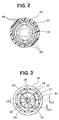
- a rotation shaft 22 of a detection object such as a shaft of a throttle valve is inserted and rotatably supported to a main housing 21 of the apparatus 1 via a bearing 23.
- the rotation shaft 22 is made of a magnetic material such as iron.
- a rotor core 24 having a cylindrical cap shape is fixed to a tip (right side end) of the rotation shaft 22 by being swaged.
- a stator core 25 is concentrically arranged inner side of the rotor core 24.
- Each of the rotor core 24 and the stator core 25 is made of a magnetic material such as iron.
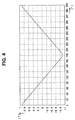
- the magnetic flux in the positive direction is decreased as the rotating position of the permanent magnet 27.
- the magnetic flux is decreased as an increment of the rotating angle in a range from 0 to 180 degree.
- the magnetic flux is increased as an increment of the rotating angle in a range from 180 to 360 degree.
- a control circuit (not-shown) detects the angular position of the rotor core 24 based on the output of the Hall IC 31.
- the shape of the permanent magnet is not limited to the ring shape, and several modifications, as shown in FIGS. 6 - 10, can be thought.
- a second embodiment of the present invention will be explained with reference to FIG. 6.
- portions, which are substantially the same portions as those of the above-described embodiment, are put the same symbols to omit explanations.
- two arc-shaped permanent magnets 39 are disposed in the rotor core 24.
- a resin separates the permanent magnets 39.
- Each of the stator cores 25 has a circumferential length larger than an inner surface of the permanent magnet 39.
- the rotation lever 41 is pressed to a predetermined rotational direction by a twist coil spring 43, and is automatically returned to an initial position by a spring force.
- a through hole 44 is formed on a center of the rotating lever 41.
- a small diameter portion 45 formed on a left end of the stator core 42 is inserted into the hole 44.
- the rotating lever 41 is supported on the small diameter portion by a stopper plate 46, which is fixed on a tip portion of the small diameter portion 45 and prevents the rotation lever 41 from being removed.
- a spring washer 47 for restricting a movement of the rotation lever 41 in a thrust direction is sandwiched between the stopper plate 46 and the rotation lever 41.
- the present invention may apply to an axial gap type apparatus which has a permanent magnet disposed opposite to a stator core in an axial direction. Further, the present invention may apply to a modified radial gap type apparatus which has a permanent magnet disposed opposite to a stator core in an axial direction and a rotor core having a portion elongated to face an outer surface of the stator core.
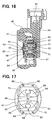
- the magnetic flux of the permanent magnets 62 from the N pole to the S pole runs through the following path: the rotor core 61 ⁇ the stator core 49 ⁇ the detecting portion 50 (the Hall IC 31) ⁇ the stator core 49 ⁇ the rotor core 61.
- the magnetic flux density (the magnetic flux density passing through the Hall IC 31) passing through the detecting portion 50 of the stator core 49 varies as shown in FIG. 19 in accordance with the rotating angle of the detection object. Therefore, the Hall IC 31 outputs a signal according to the magnetic flux density.
- the Hall IC detecting element
- the Hall IC is located on a position in the paths where the magnetic flux flows in parallel.
- the shape of the permanent magnets in the above-described 11th - 13th embodiments is not limited in the plate shape.
- the permanent magnets can be modified into an appropriate shape that is easy to manufacture in accordance with a position where the permanent magnets is located or a space for accommodating the permanent magnets.
- the permanent magnets may have different dimensions each other.
Landscapes
- Physics & Mathematics (AREA)
- General Physics & Mathematics (AREA)
- Measurement Of Length, Angles, Or The Like Using Electric Or Magnetic Means (AREA)
- Transmission And Conversion Of Sensor Element Output (AREA)
- Brushless Motors (AREA)
Abstract
Description
Claims (12)
- An angular position detecting apparatus comprising:a rotor for rotating in response to a rotation of a detection object (22), the rotor having a rotor core (24, 61, 65, 67) and a permanent magnet (27, 39, 62) fixed to the rotor core;a stator core (25, 42, 49, 51) concentrically arranged with respect to the rotor core, the stator core having a gap portion (30); anda detecting element (31) being arranged in the gap portion, for outputting a signal in response to a magnetic flux density passing through the gap portion,
wherein the gap portion (30) has a detecting portion (37, 50, 52) which is a gap having a small distance and a large gap portion (38) having a distance wider than the detecting portion for concentrating the magnetic flux into the detecting portion, andthe detecting element is located in the detecting portion. - An angular position detecting apparatus according to claim 1, wherein the detecting portion (37, 50, 52) is located in a center of the stator core (25, 42, 49, 51), and the large gap portion (38) is located on both sides of the detecting portion.
- An angular position detecting apparatus according to claim 1 or 2, wherein the large gap portion (38) is formed to decrease a distance of the gap at a radial outside of the stator core.
- An angular position detecting apparatus according to claim 3, wherein the large gap portion (38) provides a distance at a radial outer portion of the stator core (25, 42, 49, 51), which is wider than a distance between the rotor and the stator core.
- An angular position detecting apparatus according to one of claims 1 to 4, wherein the large gap portion (38) is defined by a curved surface of the stator core.
- An angular position detecting apparatus according to one of claims 1 to 5, wherein the stator core (49, 51) is formed to have an axial length decreasing toward the detecting portion (50, 52) from a radial outside.
- An angular position detecting apparatus comprising:a rotor for rotating in response to an rotation of a detection object (22), the rotor having a rotor core (24, 61, 65, 67) and a permanent magnet (27, 39, 62) fixed to the rotor core;a stator core (49, 51) concentrically arranged with respect to the rotor core, the stator core having a gap portion (30); anda detecting element (31) being arranged in the gap portion, for outputting a signal in response to a magnetic flux density passing through the gap portion,
wherein the stator core (49, 51) is formed to have an axial length decreasing toward the detecting portion from a radial outside. - An angular position detecting apparatus according to one of claims 1 to 7, wherein the permanent magnet (62) comprises a plurality of permanent magnet having magnetic poles disposed to oppose each other.
- An angular position detecting apparatus according to claim 8, further comprising gap portions (66) located on a position close to the permanent magnet (62) for preventing a short circuit of the magnetic flux between both of the magnetic poles of the permanent magnet and the stator core.
- An angular position detecting apparatus, comprising:a permanent magnet (27, 39, 62);a rotor (24, 61, 65, 67) for modulating a direction of a magnetic flux generated by the permanent magnet in response to a rotation of a detection object;a stator (25, 42, 49, 51) disposed on a path of the magnetic flux modulated by the rotor; anda detecting element (31) for detecting the magnetic flux passing through the stator core, whereinthe stator core defines a gap (30) for providing a detecting portion (37, 50, 52) where the detecting element is located, and the stator core further defines a guide portion (38) for concentrating the magnetic flux passing through the stator core into the detecting portion.
- An angular position detecting apparatus according to claim 10, wherein the guide portion (38) provides a distance wider than a distance of the detecting portion.
- An angular position detecting apparatus according to claim 11, wherein the distance provided by the guide portion (38) is decreased toward the detecting portion (37, 50, 52).
Applications Claiming Priority (6)
| Application Number | Priority Date | Filing Date | Title |
|---|---|---|---|
| JP18245499 | 1999-06-28 | ||
| JP18245499 | 1999-06-28 | ||
| JP29899799 | 1999-10-21 | ||
| JP29899799 | 1999-10-21 | ||
| JP2000055923 | 2000-02-28 | ||
| JP2000055923A JP3491596B2 (en) | 1999-06-28 | 2000-02-28 | Rotation angle detector |
Publications (3)
| Publication Number | Publication Date |
|---|---|
| EP1065473A2 true EP1065473A2 (en) | 2001-01-03 |
| EP1065473A3 EP1065473A3 (en) | 2005-12-07 |
| EP1065473B1 EP1065473B1 (en) | 2012-02-29 |
Family
ID=27325161
Family Applications (1)
| Application Number | Title | Priority Date | Filing Date |
|---|---|---|---|
| EP00113599A Expired - Lifetime EP1065473B1 (en) | 1999-06-28 | 2000-06-27 | Angular position detecting apparatus |
Country Status (3)
| Country | Link |
|---|---|
| US (1) | US6356073B1 (en) |
| EP (1) | EP1065473B1 (en) |
| JP (1) | JP3491596B2 (en) |
Cited By (8)
| Publication number | Priority date | Publication date | Assignee | Title |
|---|---|---|---|---|
| EP1120626A3 (en) * | 2000-01-26 | 2002-08-14 | Denso Corporation | Angular position measuring device |
| EP1223409A3 (en) * | 2001-01-10 | 2003-11-19 | Hitachi, Ltd. | Non-contact position sensor |
| EP1382935A1 (en) * | 2002-07-19 | 2004-01-21 | Fernsteuergeräte Kurt Oelsch GmbH | Redundant angular transducer having two magnetoresistive sensor elements |
| EP1424544A1 (en) * | 2002-11-28 | 2004-06-02 | Valeo Schalter und Sensoren GmbH | Apparatus to detect a torque acting on a shaft |
| FR2850751A1 (en) * | 2003-01-14 | 2004-08-06 | Denso Corp | ANGULAR POSITION SENSOR MEASURING MAGNETIC INDUCTION WITH HIGH LINEARITY |
| EP2080991A4 (en) * | 2006-10-31 | 2012-03-28 | Furukawa Electric Co Ltd | Rotation angle detection device |
| EP2330379A4 (en) * | 2008-09-17 | 2014-11-19 | United Automotive Elect Sys Co | An angle position sensor |
| JP2018049418A (en) * | 2016-09-21 | 2018-03-29 | アルプス電気株式会社 | Rotation input device |
Families Citing this family (37)
| Publication number | Priority date | Publication date | Assignee | Title |
|---|---|---|---|---|
| US6771065B2 (en) * | 2001-02-26 | 2004-08-03 | Woodward Governor Company | Line hall effect detector and method of sensing angular position particularly suited for electrical rotary actuator |
| US6693424B2 (en) * | 2001-06-08 | 2004-02-17 | Denso Corporation | Magnetic rotation angle sensor |
| US6703828B2 (en) * | 2001-07-25 | 2004-03-09 | American Electronic Components, Inc. | Mechanical design for a sensor to prevent an ice lock condition |
| DE10141372A1 (en) * | 2001-08-23 | 2003-03-13 | Philips Corp Intellectual Pty | Magnetoresistive angle sensor |
| JP3899909B2 (en) * | 2001-11-28 | 2007-03-28 | アイシン精機株式会社 | Rotation angle sensor |
| JP4118552B2 (en) | 2001-12-05 | 2008-07-16 | アイシン精機株式会社 | Electronic component holding structure and electronic component holding method |
| DE20200302U1 (en) * | 2002-01-10 | 2002-03-28 | Ab Elektronik Gmbh, 59368 Werne | Rotation angle sensor |
| FR2837926B1 (en) * | 2002-03-27 | 2004-05-28 | Siemens Vdo Automotive | METHOD OF MANUFACTURING A WHEEL SPEED SENSOR AND CORRESPONDING SENSOR |
| JP2004251831A (en) * | 2003-02-21 | 2004-09-09 | Aisan Ind Co Ltd | Rotary angle detector |
| US20040174159A1 (en) * | 2003-03-05 | 2004-09-09 | Claudia Ramirez | Securement feature for rotary position sensor |
| JP4098149B2 (en) * | 2003-05-08 | 2008-06-11 | 愛三工業株式会社 | Throttle control device |
| JP4233920B2 (en) * | 2003-05-15 | 2009-03-04 | 株式会社デンソー | Rotation angle detector |
| JP4079043B2 (en) * | 2003-06-13 | 2008-04-23 | 株式会社デンソー | Rotation angle detector |
| JP3983722B2 (en) * | 2003-08-04 | 2007-09-26 | 三菱電機株式会社 | Engine intake control device |
| JP4233958B2 (en) * | 2003-08-29 | 2009-03-04 | 株式会社日本自動車部品総合研究所 | Rotation angle detector |
| US20050068024A1 (en) * | 2003-09-29 | 2005-03-31 | Byram Robert James | Rotary position sensor |
| JP4165386B2 (en) * | 2003-11-28 | 2008-10-15 | アイシン精機株式会社 | Electronic component holding structure |
| US7095193B2 (en) * | 2004-05-19 | 2006-08-22 | Hr Textron, Inc. | Brushless DC motors with remote Hall sensing and methods of making the same |
| US7141966B2 (en) * | 2004-07-01 | 2006-11-28 | Denso Corporation | Rotation detecting apparatus |
| JP4232700B2 (en) * | 2004-07-01 | 2009-03-04 | 株式会社デンソー | Rotation detector |
| DE102007013755B4 (en) * | 2007-03-22 | 2020-10-29 | Te Connectivity Germany Gmbh | Indicator element for a magnetic rotary encoder |
| US7639004B2 (en) * | 2007-07-23 | 2009-12-29 | Gm Global Technology Operations, Inc. | Apparatus for sensing angular displacement between first and second rotating shafts including flux collectors |
| JP4385071B2 (en) * | 2007-12-18 | 2009-12-16 | 三菱電機株式会社 | Non-contact rotation angle detection device and manufacturing method thereof |
| US20100176803A1 (en) * | 2009-01-12 | 2010-07-15 | Infineon Technologies Ag | Angle sensor with flux guides, rotatable magnet and magnetic sensor |
| US10704925B2 (en) * | 2009-01-12 | 2020-07-07 | Infineon Technologies Ag | Sensor and method for determining angular position including measuring magnetic field lines at a distance greater than the inner radius and less than the outer radius of a ring magnet, and at a distance greater than the outer radius or less than the inner radius |
| JP5818104B2 (en) | 2012-10-12 | 2015-11-18 | 株式会社デンソー | Rotation angle detector |
| US9267781B2 (en) * | 2013-11-19 | 2016-02-23 | Infineon Technologies Ag | On-axis magnetic field angle sensors, systems and methods |
| JP2015145816A (en) * | 2014-02-03 | 2015-08-13 | アイシン精機株式会社 | displacement sensor |
| US9927498B2 (en) * | 2014-06-06 | 2018-03-27 | Infineon Technologies Ag | Magnetic sensor device comprising a ring-shaped magnet and a sensor chip in a common package |
| US9892836B2 (en) | 2015-01-26 | 2018-02-13 | Infineon Technologies Ag | Rotary encoder with shielded magnet |
| DE102016009006B4 (en) | 2015-07-29 | 2024-01-25 | Infineon Technologies Ag | DRIVE TRAIN OF A MOTOR VEHICLE SYSTEM HAVING A SHAFT-INTEGRATED ANGLE SCANNING DEVICE |
| PL3171137T3 (en) * | 2015-11-23 | 2018-09-28 | Baumer Hübner GmbH | Rotary encoder assembly |
| JP6766849B2 (en) * | 2018-01-16 | 2020-10-14 | 株式会社デンソー | Rotation angle detector |
| JP6895940B2 (en) * | 2018-11-19 | 2021-06-30 | 三菱電機株式会社 | Manufacturing method of rotation angle detection device, rotation electric machine, automobile drive system, and rotation angle detection device |
| JP7412205B2 (en) * | 2020-02-12 | 2024-01-12 | ジヤトコ株式会社 | Device |
| JP7465104B2 (en) * | 2020-02-12 | 2024-04-10 | ジヤトコ株式会社 | Device |
| CN111779583B (en) * | 2020-07-06 | 2022-07-05 | 长春理工大学 | An electronic throttle valve and control method suitable for HEV mild-hybrid vehicles |
Citations (3)
| Publication number | Priority date | Publication date | Assignee | Title |
|---|---|---|---|---|
| US5164668A (en) | 1991-12-06 | 1992-11-17 | Honeywell, Inc. | Angular position sensor with decreased sensitivity to shaft position variability |
| EP0575971A1 (en) | 1992-06-22 | 1993-12-29 | Durakool Incorporated | Contactless angular position sensor |
| EP0665416A1 (en) | 1994-02-01 | 1995-08-02 | Moving Magnet Technologies S.A. | Magnetic position sensor with Hall-element |
Family Cites Families (8)
| Publication number | Priority date | Publication date | Assignee | Title |
|---|---|---|---|---|
| JPS54114267A (en) * | 1978-02-24 | 1979-09-06 | Nippon Soken | Azimuth detector |
| JPH082630Y2 (en) * | 1990-08-27 | 1996-01-29 | 星和電機株式会社 | Magnetic sensor |
| FR2670286B1 (en) | 1990-12-05 | 1993-03-26 | Moving Magnet Tech | MAGNETIC POSITION AND SPEED SENSOR WITH HALL PROBE. |
| US5789917A (en) * | 1990-12-05 | 1998-08-04 | Moving Magnet Technologie Sa | Magnetic position sensor with hall probe formed in an air gap of a stator |
| JPH0534425A (en) * | 1991-07-26 | 1993-02-09 | Nippon Telegr & Teleph Corp <Ntt> | Magnetic field concentrator |
| DE19630764A1 (en) | 1995-09-29 | 1997-04-03 | Bosch Gmbh Robert | Contact free identification device for relative movement |
| DE19634282A1 (en) | 1996-08-24 | 1998-02-26 | Bosch Gmbh Robert | Measuring device for contactless detection of an angle of rotation |
| DE19634281C2 (en) | 1996-08-24 | 2000-01-27 | Bosch Gmbh Robert | Measuring device for contactless detection of an angle of rotation or a linear movement |
-
2000
- 2000-02-28 JP JP2000055923A patent/JP3491596B2/en not_active Expired - Lifetime
- 2000-06-19 US US09/598,986 patent/US6356073B1/en not_active Expired - Lifetime
- 2000-06-27 EP EP00113599A patent/EP1065473B1/en not_active Expired - Lifetime
Patent Citations (3)
| Publication number | Priority date | Publication date | Assignee | Title |
|---|---|---|---|---|
| US5164668A (en) | 1991-12-06 | 1992-11-17 | Honeywell, Inc. | Angular position sensor with decreased sensitivity to shaft position variability |
| EP0575971A1 (en) | 1992-06-22 | 1993-12-29 | Durakool Incorporated | Contactless angular position sensor |
| EP0665416A1 (en) | 1994-02-01 | 1995-08-02 | Moving Magnet Technologies S.A. | Magnetic position sensor with Hall-element |
Cited By (12)
| Publication number | Priority date | Publication date | Assignee | Title |
|---|---|---|---|---|
| EP1120626A3 (en) * | 2000-01-26 | 2002-08-14 | Denso Corporation | Angular position measuring device |
| US6476600B2 (en) | 2000-01-26 | 2002-11-05 | Denso Corporation | Angular position measuring device |
| EP1223409A3 (en) * | 2001-01-10 | 2003-11-19 | Hitachi, Ltd. | Non-contact position sensor |
| USRE40523E1 (en) | 2001-01-10 | 2008-09-30 | Hitachi, Ltd. | Non-contact rotational position sensor and throttle valve assembly including non-contact rotational position sensor |
| EP1382935A1 (en) * | 2002-07-19 | 2004-01-21 | Fernsteuergeräte Kurt Oelsch GmbH | Redundant angular transducer having two magnetoresistive sensor elements |
| EP1424544A1 (en) * | 2002-11-28 | 2004-06-02 | Valeo Schalter und Sensoren GmbH | Apparatus to detect a torque acting on a shaft |
| FR2850751A1 (en) * | 2003-01-14 | 2004-08-06 | Denso Corp | ANGULAR POSITION SENSOR MEASURING MAGNETIC INDUCTION WITH HIGH LINEARITY |
| US7298395B2 (en) | 2003-01-14 | 2007-11-20 | Denso Corporation | Angular position sensor working to measure high linearity magnetic flux density |
| EP2080991A4 (en) * | 2006-10-31 | 2012-03-28 | Furukawa Electric Co Ltd | Rotation angle detection device |
| EP2330379A4 (en) * | 2008-09-17 | 2014-11-19 | United Automotive Elect Sys Co | An angle position sensor |
| JP2018049418A (en) * | 2016-09-21 | 2018-03-29 | アルプス電気株式会社 | Rotation input device |
| EP3318951A3 (en) * | 2016-09-21 | 2018-06-27 | Alps Electric Co., Ltd. | Rotational input device |
Also Published As
| Publication number | Publication date |
|---|---|
| JP3491596B2 (en) | 2004-01-26 |
| US6356073B1 (en) | 2002-03-12 |
| EP1065473B1 (en) | 2012-02-29 |
| JP2001188003A (en) | 2001-07-10 |
| EP1065473A3 (en) | 2005-12-07 |
Similar Documents
| Publication | Publication Date | Title |
|---|---|---|
| EP1065473B1 (en) | Angular position detecting apparatus | |
| JP3596667B2 (en) | Rotation angle detector | |
| US6501265B2 (en) | Angular position detection device having linear output characteristics | |
| US8237432B2 (en) | Rotation angle sensor | |
| US7166996B2 (en) | Position sensor utilizing a linear hall-effect sensor | |
| US6841993B2 (en) | Bearing provided with rotation sensor and motor employing the same | |
| US6414482B1 (en) | Non-contact type rotational angle sensor and sensor core used in the sensor | |
| US7071683B2 (en) | Rotation angle sensing device having enlarged detectable angle range | |
| US20100084215A1 (en) | Torque detector, method of producing same and electric power steering device | |
| US8330456B2 (en) | Rotational angle sensing device | |
| CN101213431A (en) | Sensor device for detecting angular differences | |
| JP2002206913A (en) | Non-contact rotary position sensor and throttle valve assembly having non-contact rotary position sensor | |
| US20090243600A1 (en) | Rotation sensor unit | |
| WO2010026948A1 (en) | Angle sensor | |
| CN101523176A (en) | Torque detector, method of producing the torque detector, and electric power steering device | |
| US20190044417A1 (en) | Sensor magnet and motor | |
| US20020186009A1 (en) | Magnetic rotation angle sensor | |
| JP3496581B2 (en) | Rotation angle detector | |
| JP3886434B2 (en) | Torque sensor assembly method | |
| JP2001510576A (en) | Measuring device to detect rotation angle without contact | |
| JP4233920B2 (en) | Rotation angle detector | |
| JPH01186151A (en) | Brushless motor | |
| JP2004122087A (en) | Rotor support structure | |
| JP3891045B2 (en) | Rotation angle detector | |
| JP2005291997A (en) | Non-contact position sensor |
Legal Events
| Date | Code | Title | Description |
|---|---|---|---|
| PUAI | Public reference made under article 153(3) epc to a published international application that has entered the european phase |
Free format text: ORIGINAL CODE: 0009012 |
|
| AK | Designated contracting states |
Kind code of ref document: A2 Designated state(s): AT BE CH CY DE DK ES FI FR GB GR IE IT LI LU MC NL PT SE |
|
| AX | Request for extension of the european patent |
Free format text: AL;LT;LV;MK;RO;SI |
|
| PUAL | Search report despatched |
Free format text: ORIGINAL CODE: 0009013 |
|
| AK | Designated contracting states |
Kind code of ref document: A3 Designated state(s): AT BE CH CY DE DK ES FI FR GB GR IE IT LI LU MC NL PT SE |
|
| AX | Request for extension of the european patent |
Extension state: AL LT LV MK RO SI |
|
| 17P | Request for examination filed |
Effective date: 20051213 |
|
| AKX | Designation fees paid |
Designated state(s): DE FR GB |
|
| 17Q | First examination report despatched |
Effective date: 20080408 |
|
| GRAP | Despatch of communication of intention to grant a patent |
Free format text: ORIGINAL CODE: EPIDOSNIGR1 |
|
| GRAS | Grant fee paid |
Free format text: ORIGINAL CODE: EPIDOSNIGR3 |
|
| GRAA | (expected) grant |
Free format text: ORIGINAL CODE: 0009210 |
|
| AK | Designated contracting states |
Kind code of ref document: B1 Designated state(s): DE FR GB |
|
| REG | Reference to a national code |
Ref country code: GB Ref legal event code: FG4D |
|
| REG | Reference to a national code |
Ref country code: DE Ref legal event code: R096 Ref document number: 60046957 Country of ref document: DE Effective date: 20120419 |
|
| PLBE | No opposition filed within time limit |
Free format text: ORIGINAL CODE: 0009261 |
|
| STAA | Information on the status of an ep patent application or granted ep patent |
Free format text: STATUS: NO OPPOSITION FILED WITHIN TIME LIMIT |
|
| 26N | No opposition filed |
Effective date: 20121130 |
|
| REG | Reference to a national code |
Ref country code: DE Ref legal event code: R097 Ref document number: 60046957 Country of ref document: DE Effective date: 20121130 |
|
| REG | Reference to a national code |
Ref country code: FR Ref legal event code: PLFP Year of fee payment: 16 |
|
| REG | Reference to a national code |
Ref country code: FR Ref legal event code: PLFP Year of fee payment: 17 |
|
| REG | Reference to a national code |
Ref country code: FR Ref legal event code: PLFP Year of fee payment: 18 |
|
| REG | Reference to a national code |
Ref country code: FR Ref legal event code: PLFP Year of fee payment: 19 |
|
| PGFP | Annual fee paid to national office [announced via postgrant information from national office to epo] |
Ref country code: DE Payment date: 20190619 Year of fee payment: 20 |
|
| PGFP | Annual fee paid to national office [announced via postgrant information from national office to epo] |
Ref country code: FR Payment date: 20190619 Year of fee payment: 20 |
|
| PGFP | Annual fee paid to national office [announced via postgrant information from national office to epo] |
Ref country code: GB Payment date: 20190619 Year of fee payment: 20 |
|
| REG | Reference to a national code |
Ref country code: DE Ref legal event code: R071 Ref document number: 60046957 Country of ref document: DE |
|
| REG | Reference to a national code |
Ref country code: GB Ref legal event code: PE20 Expiry date: 20200626 |
|
| PG25 | Lapsed in a contracting state [announced via postgrant information from national office to epo] |
Ref country code: GB Free format text: LAPSE BECAUSE OF EXPIRATION OF PROTECTION Effective date: 20200626 |