EP1065367A2 - Ventisitz für eine Kugelventilvorrichtung eines hydraulisch betätigten Kraftstoffeinspritzventils - Google Patents
Ventisitz für eine Kugelventilvorrichtung eines hydraulisch betätigten Kraftstoffeinspritzventils Download PDFInfo
- Publication number
- EP1065367A2 EP1065367A2 EP00113944A EP00113944A EP1065367A2 EP 1065367 A2 EP1065367 A2 EP 1065367A2 EP 00113944 A EP00113944 A EP 00113944A EP 00113944 A EP00113944 A EP 00113944A EP 1065367 A2 EP1065367 A2 EP 1065367A2
- Authority
- EP
- European Patent Office
- Prior art keywords
- valve seat
- pin
- valve member
- passage
- curvature
- Prior art date
- Legal status (The legal status is an assumption and is not a legal conclusion. Google has not performed a legal analysis and makes no representation as to the accuracy of the status listed.)
- Withdrawn
Links
- 239000012530 fluid Substances 0.000 claims description 61
- 239000000446 fuel Substances 0.000 claims description 53
- 239000000463 material Substances 0.000 claims description 9
- 238000000034 method Methods 0.000 claims description 5
- 239000010687 lubricating oil Substances 0.000 claims description 4
- 239000002283 diesel fuel Substances 0.000 claims description 2
- 238000002347 injection Methods 0.000 description 10
- 239000007924 injection Substances 0.000 description 10
- 150000001875 compounds Chemical class 0.000 description 3
- 238000007493 shaping process Methods 0.000 description 2
- 238000013459 approach Methods 0.000 description 1
- 230000000712 assembly Effects 0.000 description 1
- 238000000429 assembly Methods 0.000 description 1
- 230000009286 beneficial effect Effects 0.000 description 1
- 230000015556 catabolic process Effects 0.000 description 1
- 230000006835 compression Effects 0.000 description 1
- 238000007906 compression Methods 0.000 description 1
- 238000005336 cracking Methods 0.000 description 1
- 238000006731 degradation reaction Methods 0.000 description 1
- 239000011796 hollow space material Substances 0.000 description 1
- 230000000977 initiatory effect Effects 0.000 description 1
- 238000004519 manufacturing process Methods 0.000 description 1
- 238000003801 milling Methods 0.000 description 1
Images
Classifications
-
- F—MECHANICAL ENGINEERING; LIGHTING; HEATING; WEAPONS; BLASTING
- F02—COMBUSTION ENGINES; HOT-GAS OR COMBUSTION-PRODUCT ENGINE PLANTS
- F02M—SUPPLYING COMBUSTION ENGINES IN GENERAL WITH COMBUSTIBLE MIXTURES OR CONSTITUENTS THEREOF
- F02M59/00—Pumps specially adapted for fuel-injection and not provided for in groups F02M39/00 -F02M57/00, e.g. rotary cylinder-block type of pumps
- F02M59/02—Pumps specially adapted for fuel-injection and not provided for in groups F02M39/00 -F02M57/00, e.g. rotary cylinder-block type of pumps of reciprocating-piston or reciprocating-cylinder type
- F02M59/10—Pumps specially adapted for fuel-injection and not provided for in groups F02M39/00 -F02M57/00, e.g. rotary cylinder-block type of pumps of reciprocating-piston or reciprocating-cylinder type characterised by the piston-drive
- F02M59/105—Pumps specially adapted for fuel-injection and not provided for in groups F02M39/00 -F02M57/00, e.g. rotary cylinder-block type of pumps of reciprocating-piston or reciprocating-cylinder type characterised by the piston-drive hydraulic drive
-
- F—MECHANICAL ENGINEERING; LIGHTING; HEATING; WEAPONS; BLASTING
- F02—COMBUSTION ENGINES; HOT-GAS OR COMBUSTION-PRODUCT ENGINE PLANTS
- F02M—SUPPLYING COMBUSTION ENGINES IN GENERAL WITH COMBUSTIBLE MIXTURES OR CONSTITUENTS THEREOF
- F02M57/00—Fuel-injectors combined or associated with other devices
- F02M57/02—Injectors structurally combined with fuel-injection pumps
- F02M57/022—Injectors structurally combined with fuel-injection pumps characterised by the pump drive
- F02M57/025—Injectors structurally combined with fuel-injection pumps characterised by the pump drive hydraulic, e.g. with pressure amplification
-
- F—MECHANICAL ENGINEERING; LIGHTING; HEATING; WEAPONS; BLASTING
- F02—COMBUSTION ENGINES; HOT-GAS OR COMBUSTION-PRODUCT ENGINE PLANTS
- F02M—SUPPLYING COMBUSTION ENGINES IN GENERAL WITH COMBUSTIBLE MIXTURES OR CONSTITUENTS THEREOF
- F02M59/00—Pumps specially adapted for fuel-injection and not provided for in groups F02M39/00 -F02M57/00, e.g. rotary cylinder-block type of pumps
- F02M59/44—Details, components parts, or accessories not provided for in, or of interest apart from, the apparatus of groups F02M59/02 - F02M59/42; Pumps having transducers, e.g. to measure displacement of pump rack or piston
- F02M59/46—Valves
- F02M59/466—Electrically operated valves, e.g. using electromagnetic or piezoelectric operating means
Definitions
- the present invention relates generally to hydraulically actuated devices having ball valve members, and more specifically to hydraulically actuated fuel injectors that use a ball and pin valve member to control actuation fluid flow into and out of the injector.
- Hydraulically-actuated fuel injection systems and/or components are known, for example in U.S. Patent No. 5,121,730 issued to Ausman et al. on 16 June 1992; U.S. Patent No. 5,271,371 issued to Meints et al. on 21 December 1993; and U.S. Patent No. 5,297,523 issued to Hafner et al. on 29 March 1994.
- a spring biased needle check opens to commence fuel injection when pressure is raised by an intensifier piston/plunger assembly to a valve opening pressure.
- the intensifier piston is acted upon by a hydraulic actuation fluid, such as engine lubricating oil, when a solenoid driven actuation fluid control valve opens the injector's high pressure inlet. Injection is ended by deactivating the solenoid to release pressure above the intensifier piston. This in turn causes a drop in fuel pressure causing the needle check to close under the action of its return spring and end injection.
- a hydraulic actuation fluid such as engine lubricating oil
- actuation fluid control valve The initiation of an injection event in all these hydraulically-actuated fuel injectors is started by energizing a solenoid to move an actuation fluid control valve to open the high pressure actuation fluid inlet passage to the injector. While some versions of this actuation fluid control valve utilize a poppet valve member or a spool valve member attached to the armature of a solenoid, other versions utilize a ball and pin valve -- a simple pin attached to the solenoid to move a ball between opposing valve seats.
- a ball and pin valve assembly in which a pin pushes a ball against a first annular valve seat, and hydraulic fluid pressure pushes the ball back against a second annular valve seat when the pin is withdrawn.
- This valve is incorporated into a fuel injector having an injector body that includes a nozzle chamber that opens to a nozzle outlet.
- a hydraulic means within the injector body pressurizes fuel in the nozzle chamber.
- a needle valve member is positioned to reciprocate in the nozzle chamber between an opened position in which the nozzle outlet is open and a closed position in which the nozzle outlet is closed.
- the pin strikes the ball with great force, and drives the ball against the first annular valve seat with great force.
- this can cause deformations of the first annular valve seat.
- This can actually be beneficial, because slight deformations of a portion of the seat to match the curvature of the ball can cause a better seal of the ball against the seat.
- U.S. patent 4,997,004 to Barkhimer does not teach this problem, and indeed does not address shaping the pin of a ball and pin valve at all, but it does disclose shaping a seat in various ways to help hold the ball in axial alignment with its seat and to minimize wear of the valve seat.
- Various types of straight edge slopes and spherical seating surfaces are disclosed, including a ball seat concavity having a compound curvature consisting of a spherical bottom portion and a forwardly and outwardly flared lead-in portion.
- the straight edge slope valve seat puts a great deal of stress on a small area.
- the spherical valve seat configuration has the advantage that the load can be distributed over the entire circle surface of the concavity, but initial engagement of the ball striking an outer forward edge of the concavity when the ball is out of axial alignment even slightly can cause wear as well.
- the compound curvature can alleviate this problem somewhat because when the ball is slightly out of alignment it will strike the flared edge of the concavity.
- accurately milling the proper curvature for manufacture of a compound curvature can be difficult and expensive.
- a hydraulically actuated device comprises a device body defining an inlet passage separated from an outlet passage by a first valve seat and a second valve seat, and a control passage that opens into an area between the first valve seat and the second valve seat.
- An essentially spherical ball valve member having a first radius of curvature is trapped between the first valve seat and the second valve seat.
- the inlet passage is fluidly isolated from the control passage by the ball valve member when the ball valve member is in contact with the second valve seat
- the outlet passage is fluidly isolated from the control passage by the ball valve member when the ball valve member is in contact with the first valve seat.
- An electrical actuator is attached to the device body.
- a pin is movable by operation of the electrical actuator to come into contact with and push against the ball along a curved striking surface of the pin having a second radius of curvature that is larger than the first radius of curvature.
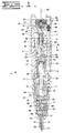
- fuel injector 4 utilizes a single two-way solenoid 31 to alternately open actuation fluid cavity 9 to actuation fluid inlet passage 6 or low pressure actuation fluid drain 8.
- the high pressure actuation fluid entering actuation fluid cavity 9 is used to apply pressure to an intensifier piston 50 or such to begin and end fuel injection, by various methods known in the art.
- Injector 4 includes an injector body 5 having an actuation fluid inlet passage 6 that is connected to source of high pressure actuation fluid, such as lubricating oil, an actuation fluid drain 8 that is connected to a low pressure actuation fluid re-circulation line, and a fuel inlet 20 connected to a source of fuel.
- Injector 4 includes a hydraulic means for pressurizing fuel within the injector during each injection event and a needle control valve that controls the opening and closing of nozzle outlet 17.
- the illustrated embodiment has a two-position actuation fluid control valve that includes a a solenoid 31 with an armature attached to a pin 35, and ball valve member (ball) 36 movable between an upper annular seat 72 and a lower annular seat 73.
- a solenoid 31 with an armature attached to a pin 35
- ball valve member (ball) 36 movable between an upper annular seat 72 and a lower annular seat 73.
- Other embodiments using the invention may utilize other types of electrical actuators 31 to move the pin 35, for example a piezo stack actuator.
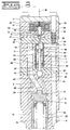
- the tip of the pin is made of a sufficiently tough material to handle the point loading that occurs when it strikes the ball 36. Additionally, the striking surface of the tip of the pin 35 is given a spherically concave shape to better absorb the impact of hitting the ball 36. Further, to spread the impact force over a wider striking surface, the cross-sectional diameter of the tip of the pin 35 is increased. This requires the diameter of the sleeve surrounding the tip of the pin 35 to the increased as well, in order to maintain proper fluid flow.
- the hardness of the pin tip 35 material should be between 55 and 62 Rockwell C (Rockwell C is a well-known scale for measuring hardness). Toughness can be defined by the "critical crack length" (K1C) of a material.
- K1C critical crack length
- the toughness of the pin 35 material should be such that K1C ⁇ 25 MPa ⁇ m where Mpa is megapascals and m is meters.
- the striking surface area 12 of the pin 35 should be made large enough so that the maximum load P on the pin 35 generated when the pin 35 strikes the ball 36 divided by the area of the striking surface 12 of the pin 35 is 1200 MPa or less.
- the spherical radius of the concave shape of the end of the pin 35 is mismatched with the spherical radius of the ball 36. Specifically, the radius of curvature of the concave depression 12 in the tip of the pin 35 is greater than the radius of curvature 14 of the ball 36. That is, the striking surface at the tip of the pin 35 is slightly flatter than the surface of the ball 36 to ensure that the ball 36 does not contact the pin 35 at its edge, which may cause chipping.
- the striking surface 12 of the pin tip 35 will deform to match the curvature of the ball 36 across a considerable percentage of the striking surface 12 of the pin 35.
- the material hardness, toughness, and dimensions must be chosen in accordance with the forces involved so that the deformation area does not extend all the way to the edge of the striking surface 12.
- the deformation area should be large enough to handle the maximum load P on the pin 35 as described above.
- the exact difference in radii of curvature that can be used with this invention may vary, but the differential radius (the difference between the to radii of curvature) must be large enough so that given the tolerances of the pin 35, the ball 36, and the motion of the pin 35 relative to the ball 36, there is a negligible chance that the sharp edge of the pin 35 strikes the ball 36 first. However, if the differential is too large it may cause cracking of the pin 35, because too much of the force of impact will be delivered to too small an initial area of the pin 35.
- differential radius of curvature of the tip (striking) surface of the pin 35 should be somewhat larger, but no more than about 60 percent, and preferably just about half, of the radius of curvature of the ball 36.
- the ball 36 has a diameter of 3.175 mm, and therefore has a radius of curvature of about 1.6 mm.
- the preferred maximum differential radius is about 0.8 mm. That is, the concave depression (striking surface) in the tip of the pin 35 is kept within 0.8 mm larger of the radius of curvature 14 of the ball 36.
- the shape of the receiving sleeve forming the annular seat 73 is conical to reduce edge load as the ball 36 strikes the seat 33.
- the seat can also be curved if desired to reduce somewhat the point load of the ball 36 striking the seat 33.
- injector body 5 is made up of many machined bodies that include the various passages and bores, which are attached to one another so as to ensure a close alignment between the centers of pin guide bore 33, the upper annular valve seat 72, and the lower annular valve seat 73.
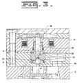
- the actuation fluid control valve of injector 4 can be thought of as including the two-way solenoid 31 that is attached to a pin 35, which remains in contact with ball 36 except when pin 35 is fully retracted. Pin 35 is biased by a compression spring 38 and the hydraulic force on ball 36 toward a retracted position (as shown in Fig. 3). In this position, the ball 36 closes the upper annular seat 72 and opens the lower annular seat 73. This allows high pressure actuation fluid to flow into the actuation fluid cavity 9.
- Each injection sequence is started by energizing solenoid 31.
- solenoid 31 When solenoid 31 is energized, pin 35 moves downward pushing ball 36 to open the upper annular seat 72 and close the lower annular seat 73. This cuts off the high pressure hydraulic fluid in the actuation fluid inlet 6 from the actuation fluid cavity 9, and simultaneously opens the actuation fluid cavity 9 to the low pressure actuation fluid drain 8.
- the tip of the pin 35 and the ball 36 have cooperating spherical services, to spread the impact of the pin 35 striking the ball 36 over a sufficient area.
- the tip of the pin 35 and the ball 36 have mismatched striking areas. That is, they are formed so that their services have different spherical radii. This ensures that contact between the pin and the ball is at or very close to the axis center, and not at the edges of the tip of the pin 35, which could cause chipping of the pin 35.
- the pin 35 must be made of sufficient toughness. There are several reasons for this. Initially, the toughness must be great enough for the pin 35 to handle the impact loads that occur when the ball 36 strikes it. Additionally, the pin 35 must be of sufficient toughness to allow the point load of the ball 36 striking the pin 35 to plastically the form and wear into the pin tip to provide sufficient area to support the impact loads.
- solenoid 31 is deenergized. This causes ball 36 to move to open seat 73 and close seat 72. This allows the high pressure hydraulic fluid from the actuation fluid inlet 6 to flow through hollow space 47, past the ball 36, and into the actuation fluid cavity 9.
- a hydraulically actuated device comprising:
- the hydraulically actuated device wherein the electrical actuator (31) is a piezo stack.
- a hydraulically actuated device further comprising a fuel inlet (20) fluidly connected to a source of engine fuel, and wherein the ball valve member (36) comes into contact with the first seat (73) against a conical surface of the first valve seat (73).
- a hydraulically actuated fuel injector for injecting a fuel fluid into an engine comprising:
- the hydraulically actuated fuel injector wherein the electrical actuator (31) is a piezo stack.
- the hydraulically actuated fuel injector wherein the first fluid passage is an inlet passage (6) fluidly connected to a source of high pressure hydraulic fluid and the second fluid passage is an outlet passage (8) fluidly connected to a volume of low pressure hydraulic fluid.
- the hydraulically actuated fuel injector further comprising a fuel inlet (20) for admitting fuel fluid to the fuel injector, wherein a hydraulic fluid supplied to the first fluid passage (6) is fluidly isolated from the fuel fluid admitted via the fuel inlet (20).
- the hydraulically actuated device wherein said pin (35) comprises material of hardness between 55 and 62 Rockwell C.
- the hydraulically actuated device wherein said pin (35) comprises material of a toughness corresponding to K1C ⁇ 25 MPa ⁇ m.
Landscapes
- Engineering & Computer Science (AREA)
- Chemical & Material Sciences (AREA)
- Combustion & Propulsion (AREA)
- Mechanical Engineering (AREA)
- General Engineering & Computer Science (AREA)
- Physics & Mathematics (AREA)
- Electromagnetism (AREA)
- Fuel-Injection Apparatus (AREA)
- Magnetically Actuated Valves (AREA)
- Multiple-Way Valves (AREA)
Applications Claiming Priority (2)
| Application Number | Priority Date | Filing Date | Title |
|---|---|---|---|
| US09/343,374 US6142394A (en) | 1999-06-30 | 1999-06-30 | Valve seat for a ball and pin valve member in a hydraulically actuated fuel injector |
| US343374 | 1999-06-30 |
Publications (2)
| Publication Number | Publication Date |
|---|---|
| EP1065367A2 true EP1065367A2 (de) | 2001-01-03 |
| EP1065367A3 EP1065367A3 (de) | 2003-10-15 |
Family
ID=23345856
Family Applications (1)
| Application Number | Title | Priority Date | Filing Date |
|---|---|---|---|
| EP00113944A Withdrawn EP1065367A3 (de) | 1999-06-30 | 2000-06-30 | Ventisitz für eine Kugelventilvorrichtung eines hydraulisch betätigten Kraftstoffeinspritzventils |
Country Status (2)
| Country | Link |
|---|---|
| US (1) | US6142394A (de) |
| EP (1) | EP1065367A3 (de) |
Cited By (1)
| Publication number | Priority date | Publication date | Assignee | Title |
|---|---|---|---|---|
| CN102529923A (zh) * | 2010-12-22 | 2012-07-04 | 日立汽车系统株式会社 | 制动装置 |
Families Citing this family (11)
| Publication number | Priority date | Publication date | Assignee | Title |
|---|---|---|---|---|
| JP3637813B2 (ja) * | 1998-09-07 | 2005-04-13 | 株式会社デンソー | Abs用調圧リザーバ及びそれを用いた車両用ブレーキ装置 |
| US6354270B1 (en) * | 2000-06-29 | 2002-03-12 | Caterpillar Inc. | Hydraulically actuated fuel injector including a pilot operated spool valve assembly and hydraulic system using same |
| US6668856B2 (en) | 2002-01-10 | 2003-12-30 | Woodward Governor Company | Valve with guided ball |
| US6681143B2 (en) * | 2002-03-19 | 2004-01-20 | Siemens Diesel Systems Technology | Match grinding of spool to control valve body of oil activated fuel injector |
| AT500889B8 (de) * | 2004-08-06 | 2007-02-15 | Bosch Gmbh Robert | Vorrichtung zum einspritzen von kraftstoff in den brennraum einer brennkraftmaschine |
| US8375992B2 (en) * | 2005-12-15 | 2013-02-19 | Parker-Hannifin Corporation | Adjustable pressure control valves |
| NO324956B1 (no) * | 2006-06-15 | 2008-01-14 | Ziebel As | Anordning ved styrt tilbakeslagsventil |
| FR2973092B1 (fr) * | 2011-03-25 | 2016-09-02 | Bosch Gmbh Robert | Dispositif d'obturation, regulateur de pression comportant un tel dispositif, dispositif d'injection diesel comportant un tel regulateur, moteur diesel et vehicule comportant un tel moteur |
| US9212639B2 (en) * | 2012-11-02 | 2015-12-15 | Caterpillar Inc. | Debris robust fuel injector with co-axial control valve members and fuel system using same |
| FR2999658A1 (fr) * | 2012-12-18 | 2014-06-20 | Delphi Technologies Holding | Vanne haute pression |
| US10544771B2 (en) * | 2017-06-14 | 2020-01-28 | Caterpillar Inc. | Fuel injector body with counterbore insert |
Citations (5)
| Publication number | Priority date | Publication date | Assignee | Title |
|---|---|---|---|---|
| US4997004A (en) | 1986-01-29 | 1991-03-05 | Bkm, Inc. | High cycle solenoid valve |
| US5121730A (en) | 1991-10-11 | 1992-06-16 | Caterpillar Inc. | Methods of conditioning fluid in an electronically-controlled unit injector for starting |
| US5271371A (en) | 1991-10-11 | 1993-12-21 | Caterpillar Inc. | Actuator and valve assembly for a hydraulically-actuated electronically-controlled injector |
| US5297523A (en) | 1993-02-26 | 1994-03-29 | Caterpillar Inc. | Tuned actuating fluid inlet manifold for a hydraulically-actuated fuel injection system |
| US5833146A (en) | 1996-09-09 | 1998-11-10 | Caterpillar Inc. | Valve assembly with coupled seats and fuel injector using same |
Family Cites Families (16)
| Publication number | Priority date | Publication date | Assignee | Title |
|---|---|---|---|---|
| US3731880A (en) * | 1971-10-08 | 1973-05-08 | Gen Motors Corp | Ball valve electromagnetic fuel injector |
| US4434765A (en) * | 1981-10-30 | 1984-03-06 | Colt Industries Operating Corp. | Fuel injection apparatus and system |
| DE3312067A1 (de) * | 1983-04-02 | 1984-10-04 | Robert Bosch Gmbh, 7000 Stuttgart | Elektromagnetisch betaetigbares ventil |
| US4509716A (en) * | 1983-09-30 | 1985-04-09 | Cts Corporation | Electromagnetically operated hydraulic valve device with snap-together valve housing |
| US4635849A (en) * | 1984-05-03 | 1987-01-13 | Nippon Soken, Inc. | Piezoelectric low-pressure fuel injector |
| DE3516918A1 (de) * | 1985-05-10 | 1986-11-13 | Pierburg Gmbh & Co Kg, 4040 Neuss | Elektromagnetisches, intermittierendes einspritzventil |
| US4620565A (en) * | 1985-09-03 | 1986-11-04 | Allied Corporation | Integrated three way and isolation solenoid valve |
| DE8711602U1 (de) * | 1987-08-27 | 1988-12-22 | Robert Bosch Gmbh, 7000 Stuttgart | Elektromagnetventil |
| JPH03199789A (ja) * | 1989-12-28 | 1991-08-30 | Aisin Aw Co Ltd | 電磁弁 |
| US5145148A (en) * | 1991-11-14 | 1992-09-08 | Siemens Automotive L.P. | Solenoid valve operating mechanism comprising a pin having a plastic sleeve molded onto a metal core |
| JP3294382B2 (ja) * | 1992-10-30 | 2002-06-24 | 株式会社デンソー | 流量制御弁 |
| US5606992A (en) * | 1994-05-18 | 1997-03-04 | Coltec Industries Inc. | Pulse width modulated solenoid |
| DE4428385B4 (de) * | 1994-08-11 | 2005-03-17 | Robert Bosch Gmbh | Ventilkörper |
| US5467797A (en) * | 1994-12-23 | 1995-11-21 | General Motors Corporation | Two-position three-way solenoid valve |
| US5720318A (en) * | 1995-05-26 | 1998-02-24 | Caterpillar Inc. | Solenoid actuated miniservo spool valve |
| DE19537382A1 (de) * | 1995-10-07 | 1997-04-10 | Bosch Gmbh Robert | Elektromagnetisch betätigbares Ventil, insbesondere Brennstoffeinspritzventil |
-
1999
- 1999-06-30 US US09/343,374 patent/US6142394A/en not_active Expired - Fee Related
-
2000
- 2000-06-30 EP EP00113944A patent/EP1065367A3/de not_active Withdrawn
Patent Citations (5)
| Publication number | Priority date | Publication date | Assignee | Title |
|---|---|---|---|---|
| US4997004A (en) | 1986-01-29 | 1991-03-05 | Bkm, Inc. | High cycle solenoid valve |
| US5121730A (en) | 1991-10-11 | 1992-06-16 | Caterpillar Inc. | Methods of conditioning fluid in an electronically-controlled unit injector for starting |
| US5271371A (en) | 1991-10-11 | 1993-12-21 | Caterpillar Inc. | Actuator and valve assembly for a hydraulically-actuated electronically-controlled injector |
| US5297523A (en) | 1993-02-26 | 1994-03-29 | Caterpillar Inc. | Tuned actuating fluid inlet manifold for a hydraulically-actuated fuel injection system |
| US5833146A (en) | 1996-09-09 | 1998-11-10 | Caterpillar Inc. | Valve assembly with coupled seats and fuel injector using same |
Cited By (2)
| Publication number | Priority date | Publication date | Assignee | Title |
|---|---|---|---|---|
| CN102529923A (zh) * | 2010-12-22 | 2012-07-04 | 日立汽车系统株式会社 | 制动装置 |
| CN102529923B (zh) * | 2010-12-22 | 2015-08-26 | 日立汽车系统株式会社 | 制动装置 |
Also Published As
| Publication number | Publication date |
|---|---|
| US6142394A (en) | 2000-11-07 |
| EP1065367A3 (de) | 2003-10-15 |
Similar Documents
| Publication | Publication Date | Title |
|---|---|---|
| US6142394A (en) | Valve seat for a ball and pin valve member in a hydraulically actuated fuel injector | |
| EP1117927B1 (de) | Hydraulisch-betätigtes kraftstoffeinspritzventil mit einem immer unter betätigungsdruck stehenden druckübersetzungskolben | |
| EP0828073B1 (de) | Ventilanordnung mit gekoppelten Ventilsitzen und ihre Verwendung in einem Kraftstoffeinspritzventil | |
| US5682858A (en) | Hydraulically-actuated fuel injector with pressure spike relief valve | |
| CN101415934B (zh) | 燃料喷射器 | |
| CN101529081B (zh) | 具有轴向上压力平衡的控制阀的喷射器 | |
| EP1076768B1 (de) | Hydraulisch betätigtes kraftstoffeinspritzventil mit hydraulisch unterstützter nadelventilschliessung | |
| US6595189B2 (en) | Method of reducing noise in a mechanically actuated fuel injection system and engine using same | |
| KR20010101179A (ko) | 유압이 보강된 액츄에이터가 포함된 이중개폐형 제어밸브 | |
| GB2334308A (en) | A control valve for a fuel injector and having a multi piece valve member with damping | |
| CN110546376B (zh) | 燃料喷射阀 | |
| US20060284129A1 (en) | Electromagnetic actuator and method for controlling fluid flow | |
| US6454189B1 (en) | Reverse acting nozzle valve and fuel injector using same | |
| US6129072A (en) | Hydraulically actuated device having a ball valve member | |
| US6059203A (en) | Valve assembly with concentrically linked components and fuel injector using same | |
| US20040163721A1 (en) | Hard coating on a stator for improving the durability of a solenoid actuator | |
| US6050496A (en) | Rotational actuation fluid control valve for a hydraulically actuated fuel injector | |
| US6425375B1 (en) | Piston and barrel assembly with stepped top and hydraulically-actuated fuel injector utilizing same | |
| EP2333296B1 (de) | Ventilelement für eine Flüssigkeitsventilanordnung | |
| EP1247975B1 (de) | Brennstoffeinspritzventil mit einem frei beweglichen Kolben | |
| US6575137B2 (en) | Piston and barrel assembly with stepped top and hydraulically-actuated fuel injector utilizing same | |
| CN104081037B (zh) | 用于内燃机的燃料喷射阀 | |
| CN105917109A (zh) | 燃料喷射器 | |
| EP1536131A1 (de) | Druckübersetzer mit Führungseinsatz für einen Kraftstoffinjektor | |
| GB2332713A (en) | A pump assembly, for a fuel injector, having a seal which isolates part of a pressure surface on the pump piston |
Legal Events
| Date | Code | Title | Description |
|---|---|---|---|
| PUAI | Public reference made under article 153(3) epc to a published international application that has entered the european phase |
Free format text: ORIGINAL CODE: 0009012 |
|
| AK | Designated contracting states |
Kind code of ref document: A2 Designated state(s): AT BE CH CY DE DK ES FI FR GB GR IE IT LI LU MC NL PT SE |
|
| AX | Request for extension of the european patent |
Free format text: AL;LT;LV;MK;RO;SI |
|
| PUAL | Search report despatched |
Free format text: ORIGINAL CODE: 0009013 |
|
| AK | Designated contracting states |
Kind code of ref document: A3 Designated state(s): AT BE CH CY DE DK ES FI FR GB GR IE IT LI LU MC NL PT SE |
|
| AX | Request for extension of the european patent |
Extension state: AL LT LV MK RO SI |
|
| AKX | Designation fees paid | ||
| REG | Reference to a national code |
Ref country code: DE Ref legal event code: 8566 |
|
| STAA | Information on the status of an ep patent application or granted ep patent |
Free format text: STATUS: THE APPLICATION IS DEEMED TO BE WITHDRAWN |
|
| 18D | Application deemed to be withdrawn |
Effective date: 20040416 |