EP1065344A2 - Turbine blade trailing edge cooling openings and slots - Google Patents
Turbine blade trailing edge cooling openings and slots Download PDFInfo
- Publication number
- EP1065344A2 EP1065344A2 EP00305460A EP00305460A EP1065344A2 EP 1065344 A2 EP1065344 A2 EP 1065344A2 EP 00305460 A EP00305460 A EP 00305460A EP 00305460 A EP00305460 A EP 00305460A EP 1065344 A2 EP1065344 A2 EP 1065344A2
- Authority
- EP
- European Patent Office
- Prior art keywords
- trailing edge
- airfoil
- side wall
- cooling
- upper portion
- Prior art date
- Legal status (The legal status is an assumption and is not a legal conclusion. Google has not performed a legal analysis and makes no representation as to the accuracy of the status listed.)
- Granted
Links
- 238000001816 cooling Methods 0.000 title claims abstract description 80
- 238000000034 method Methods 0.000 claims description 11
- 239000007789 gas Substances 0.000 description 7
- 230000001141 propulsive effect Effects 0.000 description 6
- 239000000446 fuel Substances 0.000 description 2
- 238000005457 optimization Methods 0.000 description 2
- WYTGDNHDOZPMIW-RCBQFDQVSA-N alstonine Natural products C1=CC2=C3C=CC=CC3=NC2=C2N1C[C@H]1[C@H](C)OC=C(C(=O)OC)[C@H]1C2 WYTGDNHDOZPMIW-RCBQFDQVSA-N 0.000 description 1
- 239000000203 mixture Substances 0.000 description 1
Images

Classifications
-
- F—MECHANICAL ENGINEERING; LIGHTING; HEATING; WEAPONS; BLASTING
- F01—MACHINES OR ENGINES IN GENERAL; ENGINE PLANTS IN GENERAL; STEAM ENGINES
- F01D—NON-POSITIVE DISPLACEMENT MACHINES OR ENGINES, e.g. STEAM TURBINES
- F01D5/00—Blades; Blade-carrying members; Heating, heat-insulating, cooling or antivibration means on the blades or the members
- F01D5/12—Blades
- F01D5/14—Form or construction
- F01D5/20—Specially-shaped blade tips to seal space between tips and stator
-
- F—MECHANICAL ENGINEERING; LIGHTING; HEATING; WEAPONS; BLASTING
- F01—MACHINES OR ENGINES IN GENERAL; ENGINE PLANTS IN GENERAL; STEAM ENGINES
- F01D—NON-POSITIVE DISPLACEMENT MACHINES OR ENGINES, e.g. STEAM TURBINES
- F01D5/00—Blades; Blade-carrying members; Heating, heat-insulating, cooling or antivibration means on the blades or the members
- F01D5/12—Blades
- F01D5/14—Form or construction
- F01D5/18—Hollow blades, i.e. blades with cooling or heating channels or cavities; Heating, heat-insulating or cooling means on blades
-
- F—MECHANICAL ENGINEERING; LIGHTING; HEATING; WEAPONS; BLASTING
- F01—MACHINES OR ENGINES IN GENERAL; ENGINE PLANTS IN GENERAL; STEAM ENGINES
- F01D—NON-POSITIVE DISPLACEMENT MACHINES OR ENGINES, e.g. STEAM TURBINES
- F01D5/00—Blades; Blade-carrying members; Heating, heat-insulating, cooling or antivibration means on the blades or the members
- F01D5/12—Blades
- F01D5/14—Form or construction
- F01D5/18—Hollow blades, i.e. blades with cooling or heating channels or cavities; Heating, heat-insulating or cooling means on blades
- F01D5/186—Film cooling
-
- F—MECHANICAL ENGINEERING; LIGHTING; HEATING; WEAPONS; BLASTING
- F01—MACHINES OR ENGINES IN GENERAL; ENGINE PLANTS IN GENERAL; STEAM ENGINES
- F01D—NON-POSITIVE DISPLACEMENT MACHINES OR ENGINES, e.g. STEAM TURBINES
- F01D5/00—Blades; Blade-carrying members; Heating, heat-insulating, cooling or antivibration means on the blades or the members
- F01D5/12—Blades
- F01D5/14—Form or construction
- F01D5/18—Hollow blades, i.e. blades with cooling or heating channels or cavities; Heating, heat-insulating or cooling means on blades
- F01D5/187—Convection cooling
-
- Y—GENERAL TAGGING OF NEW TECHNOLOGICAL DEVELOPMENTS; GENERAL TAGGING OF CROSS-SECTIONAL TECHNOLOGIES SPANNING OVER SEVERAL SECTIONS OF THE IPC; TECHNICAL SUBJECTS COVERED BY FORMER USPC CROSS-REFERENCE ART COLLECTIONS [XRACs] AND DIGESTS
- Y02—TECHNOLOGIES OR APPLICATIONS FOR MITIGATION OR ADAPTATION AGAINST CLIMATE CHANGE
- Y02T—CLIMATE CHANGE MITIGATION TECHNOLOGIES RELATED TO TRANSPORTATION
- Y02T50/00—Aeronautics or air transport
- Y02T50/60—Efficient propulsion technologies, e.g. for aircraft
Definitions
- This invention relates generally to turbine engines and, more particularly, to apparatus and methods for cooling a turbine blade trailing edge.
- a turbine engine typically includes a core engine having, in serial flow relationship, a high pressure compressor which compresses an airflow entering the core engine, a combustor in which a mixture of fuel and compressed air is burned to generate hot propulsive gases, and a high pressure turbine which is rotated by the hot propulsive gases.
- the high pressure turbine is connected to the high pressure compressor by a shaft so that the high pressure turbine blades drive the high pressure compressor.
- Additional compressors and turbine blades e.g., a low pressure compressor and a low pressure turbine
- turbine blades refers to the high pressure turbine blades and low pressure turbine blades.
- a turbine blade typically includes an airfoil, a platform, a shank, and a dovetail.
- the platform is connected to a root of the airfoil and the shank.
- the shank is connected to the dovetail, through which the cooling air is directed.
- the airfoil includes a leading edge and a trailing edge, with the trailing edge being relatively thin in comparison to the leading edge.
- the airfoil further includes an upper portion, a lower portion, and a tip. The tip and the root are connected to the leading edge and the trailing edge at the upper portion and the lower portion of the airfoil, respectively.
- a greater operating efficiency and power output of the turbine engine is achieved through higher operating temperatures. Operating temperatures are limited, however, by a maximum temperature tolerable by the rotating turbine blades, along with problems associated with tension and stress caused by increased rotation of the turbine blades.
- cooling air is extracted from an outlet of the compressor and utilized to cool, for example, turbine blades.
- aerodynamic efficiency creates problems with operating conditions of the airfoil, and optimization of the operating conditions creates problems with the aerodynamic efficiency.
- aerodynamic losses predominately occur at the upper portion of airfoils with a thick trailing edge due to radial distribution of the hot propulsive gases.
- a thin trailing edge increases the likelihood that the lower portion of the airfoil will fail due, at least in part, to high centrifugal stresses during operation, when combined with the high operating temperatures.
- a turbine blade airfoil in an exemplary embodiment of the invention, includes a plurality of slots on an upper portion of the airfoil and a plurality of trailing edge openings through a lower portion of the airfoil.
- the turbine blade also includes a shank, a platform, and a dovetail.
- the airfoil is connected to the platform at a root and further includes at least one cooling cavity located between a pressure side wall and a suction side wall which extend from a leading edge of the airfoil to a trailing edge of the airfoil.
- the upper portion of the airfoil includes a thin trailing edge.
- the slots extend from the pressure side wall of the airfoil to the trailing edge.
- the lower portion of the airfoil includes a thicker trailing edge than the upper portion trailing edge.
- the trailing edge openings extend through the trailing edge and provide convection cooling to the lower portion of the trailing edge.
- the slots cool the upper portion of the airfoil utilizing a combination of convection cooling for the airfoil and film cooling for the upper portion of the trailing edge.
- Utilizing the above described airfoil with the combination of slots and trailing edge openings improves the performance and durability of the turbine blade.
- the performance of the turbine blade is improved by utilizing a thin trailing edge at the upper portion of the airfoil which is effectively cooled by the slots.
- the durability of the turbine blade is improved by including a trailing edge at the lower portion of the airfoil which has a greater width than the upper portion trailing edge and which is cooled by the trailing edge openings extending through the lower portion trailing edge.
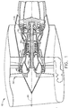
- Figure 1 is a cross sectional illustration of a turbine engine 10 symmetrical about a central axis 20.
- Engine 10 includes, in serial flow communication, a front fan 30, a multistage low pressure compressor, or booster, 40, a multistage high pressure compressor 50, a combustor 60, a high pressure turbine 70, and a multistage low pressure turbine 130.
- High pressure turbine 70 is connected to high pressure compressor 50 by a high pressure shaft 140.
- Low pressure turbine 130 is connected to front fan 30 and booster 40 by low pressure shaft 150.
- the air is compressed and continues to flow downstream through high pressure compressor 50 where the air becomes highly pressurized.
- a portion of the highly pressurized compressed air is directed to combustor 60, mixed with fuel, and ignited to generate hot, highly pressurized propulsive gases which flow further downstream and are utilized by high pressure turbine 70 to drive high pressure compressor 50.
- the hot, highly pressurized propulsive gases expand and lose some of their energy and continue to flow further downstream.
- the gases are utilized by multistage low pressure turbine 130 to drive front fan 30 and booster 40.
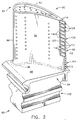
- FIG 2 illustrates a high pressure turbine blade 80 of high pressure turbine 70 (shown in Figure 1).
- high pressure turbine blade 80 includes an airfoil 82 connected to a shank 84.
- Airfoil 82 includes a leading edge 86, a trailing edge 88, a pressure side wall 90, and a suction side wall 92.
- Pressure side wall 90 is connected to suction side wall 92 at leading edge 86 and trailing edge 88.
- Airfoil 82 further includes a tip 94 and a root 96 connected by pressure side wall 90, suction side wall 92, leading edge 86, and trailing edge 88.
- Shank 84 includes a platform 98 and a dovetail 100.
- Airfoil 82 is connected at root 96 to platform 98.
- Airfoil 82 includes a trailing edge upper portion 102 which extends from tip 94, and a trailing edge lower portion 104 which extends to root 96.
- Upper portion 102 and lower portion 104 meet at a trailing edge mid-portion 106.
- Turbine blade 80 includes at least one cooling cavity (not shown in Figure 2) between pressure side wall 90 and suction side wall 92.
- the cooling cavity is in flow communication with a plurality of trailing edge slots 108 which extend along trailing edge 88 and a plurality of trailing edge openings 110 which extend through trailing edge 88.
- Trailing edge slots 108 are substantially rectangular and extend along pressure side wall 90 to trailing edge 88 at airfoil upper portion 102.
- Trailing edge openings 110 are substantially circular and extend through trailing edge 88 at airfoil lower portion 104.
- Each trailing edge slot 108 includes a recessed wall 112 separated from pressure side wall 90 by a first side wall 114 and a second side wall 116.
- a cooling cavity exit opening 118 extends from the cooling cavity to each trailing edge slot 108 adjacent recessed wall 112.
- Each recessed wall 112 extends from trailing edge 88 to cooling cavity exit opening 118.
- a plurality of lands 120 separate each trailing edge slot 108 from an adjacent trailing edge slot 108.
- Side walls 114 and 116 extend from lands 120.
- trailing edge openings 110 are substantially rectangular.
- FIGs 3 and 4 are cross-sectional illustrations of upper portion 102 and lower portion 104 of airfoil 82 shown in Figure 2.
- airfoil 82 includes a cooling cavity 122 therein.
- cooling cavity 122 is serpentine in configuration as is well known in the art.
- each cooling cavity exit opening 118 of each trailing edge slot 108 extends from cooling cavity 122 to pressure side wall 90.
- each trailing edge opening 110 extends from cooling cavity 122 through trailing edge 88 at lower portion 104.
- hot propulsive gases exit combustor 60 (shown in Figure 1), are directed through high pressure turbine 70 (shown in Figure 1), and contact each turbine blade 80. Cooling air is extracted from high pressure compressor 50 and is directed through dovetail 100 of turbine blade 80. The cooling air enters root 96 through shank 84 and dovetail 100 and is provided to the cooling cavity in airfoil 82. The cooling air cools upper portion 102 and lower portion 104 of trailing edge 88.
- Upper portion 102 is cooled by directing the cooling air into cooling cavity 122 and through trailing edge slots 108.
- the cooling air cools pressure side wall 90 and suction side wall 92 utilizing convection cooling. Due to the location of each trailing edge slot 108 on pressure side wall 90, the cooling air exits each trailing edge slot 108 through cooling cavity exit openings 118 along each recessed wall 112 and cools upper portion 102 of trailing edge 88 utilizing film cooling.
- Lower portion 104 is cooled by directing the cooling air into cooling cavity 122 and through trailing edge openings 110. The cooling air exits each trailing edge opening 110 at lower portion 104 and cools trailing edge 88 utilizing convection cooling.
- Upper portion 102 of trailing edge 88 is thin, in comparison to lower portion 104 of trailing edge 88, and reduces aerodynamic losses which would occur with thick trailing edges.
- Lower portion 104 includes a thick trailing edge 88, in comparison to upper portion 102, which reduces the likelihood that lower portion 104 will crack at root 96 along trailing edge 88 due to centrifugal stress.
- the combination of trailing edge slots 108 and trailing edge openings 110 effectively cool and preserve the aerodynamic efficiency of airfoil 82.
Landscapes
- Engineering & Computer Science (AREA)
- Mechanical Engineering (AREA)
- General Engineering & Computer Science (AREA)
- Turbine Rotor Nozzle Sealing (AREA)
Abstract
Description
- This invention relates generally to turbine engines and, more particularly, to apparatus and methods for cooling a turbine blade trailing edge.
- A turbine engine typically includes a core engine having, in serial flow relationship, a high pressure compressor which compresses an airflow entering the core engine, a combustor in which a mixture of fuel and compressed air is burned to generate hot propulsive gases, and a high pressure turbine which is rotated by the hot propulsive gases. The high pressure turbine is connected to the high pressure compressor by a shaft so that the high pressure turbine blades drive the high pressure compressor. Additional compressors and turbine blades (e.g., a low pressure compressor and a low pressure turbine) may be positioned in serial flow relationship with the core engine. As used herein, the term "turbine blades" refers to the high pressure turbine blades and low pressure turbine blades.
- A turbine blade typically includes an airfoil, a platform, a shank, and a dovetail. The platform is connected to a root of the airfoil and the shank. The shank is connected to the dovetail, through which the cooling air is directed. The airfoil includes a leading edge and a trailing edge, with the trailing edge being relatively thin in comparison to the leading edge. The airfoil further includes an upper portion, a lower portion, and a tip. The tip and the root are connected to the leading edge and the trailing edge at the upper portion and the lower portion of the airfoil, respectively.
- A greater operating efficiency and power output of the turbine engine is achieved through higher operating temperatures. Operating temperatures are limited, however, by a maximum temperature tolerable by the rotating turbine blades, along with problems associated with tension and stress caused by increased rotation of the turbine blades. Typically, cooling air is extracted from an outlet of the compressor and utilized to cool, for example, turbine blades.
- Optimization of aerodynamic efficiency creates problems with operating conditions of the airfoil, and optimization of the operating conditions creates problems with the aerodynamic efficiency. In operation, aerodynamic losses predominately occur at the upper portion of airfoils with a thick trailing edge due to radial distribution of the hot propulsive gases. However, a thin trailing edge increases the likelihood that the lower portion of the airfoil will fail due, at least in part, to high centrifugal stresses during operation, when combined with the high operating temperatures.
- In an exemplary embodiment of the invention, a turbine blade airfoil includes a plurality of slots on an upper portion of the airfoil and a plurality of trailing edge openings through a lower portion of the airfoil. The turbine blade also includes a shank, a platform, and a dovetail. The airfoil is connected to the platform at a root and further includes at least one cooling cavity located between a pressure side wall and a suction side wall which extend from a leading edge of the airfoil to a trailing edge of the airfoil.
- More specifically, the upper portion of the airfoil includes a thin trailing edge. The slots extend from the pressure side wall of the airfoil to the trailing edge. The lower portion of the airfoil includes a thicker trailing edge than the upper portion trailing edge. The trailing edge openings extend through the trailing edge and provide convection cooling to the lower portion of the trailing edge. The slots cool the upper portion of the airfoil utilizing a combination of convection cooling for the airfoil and film cooling for the upper portion of the trailing edge.
- Utilizing the above described airfoil with the combination of slots and trailing edge openings improves the performance and durability of the turbine blade. The performance of the turbine blade is improved by utilizing a thin trailing edge at the upper portion of the airfoil which is effectively cooled by the slots. The durability of the turbine blade is improved by including a trailing edge at the lower portion of the airfoil which has a greater width than the upper portion trailing edge and which is cooled by the trailing edge openings extending through the lower portion trailing edge.
- Embodiments of the invention will now be described, by way of example, with reference to the accompanying drawings, in which:
- Figure 1 is a cross sectional view of a turbine engine including a high pressure turbine;
- Figure 2 is a perspective view of the high pressure turbine blade shown in Figure 1;
- Figure 3 is a cross-sectional view of an upper portion of an airfoil utilized in the high pressure turbine blade shown in Figure 2; and
- Figure 4 is a cross-sectional view of a lower portion of the airfoil shown in Figure 2.
-
- Figure 1 is a cross sectional illustration of a
turbine engine 10 symmetrical about acentral axis 20.Engine 10 includes, in serial flow communication, afront fan 30, a multistage low pressure compressor, or booster, 40, a multistagehigh pressure compressor 50, acombustor 60, ahigh pressure turbine 70, and a multistagelow pressure turbine 130.High pressure turbine 70 is connected tohigh pressure compressor 50 by a high pressure shaft 140.Low pressure turbine 130 is connected tofront fan 30 andbooster 40 bylow pressure shaft 150. - During operation of
engine 10, air flows downstream throughfan 30 and into multistagelow pressure compressor 40. The air is compressed and continues to flow downstream throughhigh pressure compressor 50 where the air becomes highly pressurized. A portion of the highly pressurized compressed air is directed tocombustor 60, mixed with fuel, and ignited to generate hot, highly pressurized propulsive gases which flow further downstream and are utilized byhigh pressure turbine 70 to drivehigh pressure compressor 50. The hot, highly pressurized propulsive gases expand and lose some of their energy and continue to flow further downstream. The gases are utilized by multistagelow pressure turbine 130 to drivefront fan 30 andbooster 40. - Figure 2 illustrates a high
pressure turbine blade 80 of high pressure turbine 70 (shown in Figure 1). As shown in Figure 2, highpressure turbine blade 80 includes anairfoil 82 connected to ashank 84. Airfoil 82 includes a leadingedge 86, atrailing edge 88, apressure side wall 90, and asuction side wall 92.Pressure side wall 90 is connected tosuction side wall 92 at leadingedge 86 andtrailing edge 88. Airfoil 82 further includes atip 94 and aroot 96 connected bypressure side wall 90,suction side wall 92, leadingedge 86, andtrailing edge 88. Shank 84 includes aplatform 98 and adovetail 100. Airfoil 82 is connected atroot 96 toplatform 98. Airfoil 82 includes a trailing edgeupper portion 102 which extends fromtip 94, and a trailing edgelower portion 104 which extends toroot 96.Upper portion 102 andlower portion 104 meet at atrailing edge mid-portion 106. -
Turbine blade 80 includes at least one cooling cavity (not shown in Figure 2) betweenpressure side wall 90 andsuction side wall 92. The cooling cavity is in flow communication with a plurality oftrailing edge slots 108 which extend alongtrailing edge 88 and a plurality oftrailing edge openings 110 which extend throughtrailing edge 88.Trailing edge slots 108 are substantially rectangular and extend alongpressure side wall 90 to trailingedge 88 at airfoilupper portion 102.Trailing edge openings 110 are substantially circular and extend throughtrailing edge 88 at airfoillower portion 104. - Each
trailing edge slot 108 includes arecessed wall 112 separated frompressure side wall 90 by afirst side wall 114 and asecond side wall 116. A coolingcavity exit opening 118 extends from the cooling cavity to eachtrailing edge slot 108 adjacentrecessed wall 112. Eachrecessed wall 112 extends fromtrailing edge 88 to coolingcavity exit opening 118. A plurality oflands 120 separate eachtrailing edge slot 108 from an adjacenttrailing edge slot 108.Side walls lands 120. In an alternative embodiment,trailing edge openings 110 are substantially rectangular. - Figures 3 and 4 are cross-sectional illustrations of
upper portion 102 andlower portion 104 ofairfoil 82 shown in Figure 2. As shown in Figures 3 and 4,airfoil 82 includes acooling cavity 122 therein. In one embodiment,cooling cavity 122 is serpentine in configuration as is well known in the art. As shown in Figure 3, each coolingcavity exit opening 118 of eachtrailing edge slot 108 extends fromcooling cavity 122 topressure side wall 90. Whereas, as shown in Figure 4, each trailing edge opening 110 extends from coolingcavity 122 through trailingedge 88 atlower portion 104. - During operation of turbine engine 10 (shown in Figure 1), hot propulsive gases exit combustor 60 (shown in Figure 1), are directed through high pressure turbine 70 (shown in Figure 1), and contact each
turbine blade 80. Cooling air is extracted fromhigh pressure compressor 50 and is directed throughdovetail 100 ofturbine blade 80. The cooling air entersroot 96 throughshank 84 anddovetail 100 and is provided to the cooling cavity inairfoil 82. The cooling air coolsupper portion 102 andlower portion 104 of trailingedge 88. -
Upper portion 102 is cooled by directing the cooling air into coolingcavity 122 and through trailingedge slots 108. The cooling air coolspressure side wall 90 andsuction side wall 92 utilizing convection cooling. Due to the location of each trailingedge slot 108 onpressure side wall 90, the cooling air exits each trailingedge slot 108 through coolingcavity exit openings 118 along each recessedwall 112 and coolsupper portion 102 of trailingedge 88 utilizing film cooling.Lower portion 104 is cooled by directing the cooling air into coolingcavity 122 and through trailingedge openings 110. The cooling air exits each trailing edge opening 110 atlower portion 104 and cools trailingedge 88 utilizing convection cooling. -
Upper portion 102 of trailingedge 88 is thin, in comparison tolower portion 104 of trailingedge 88, and reduces aerodynamic losses which would occur with thick trailing edges.Lower portion 104 includes athick trailing edge 88, in comparison toupper portion 102, which reduces the likelihood thatlower portion 104 will crack atroot 96 along trailingedge 88 due to centrifugal stress. The combination of trailingedge slots 108 and trailingedge openings 110 effectively cool and preserve the aerodynamic efficiency ofairfoil 82. - For completeness, various aspects of the invention are set out in the following numbered clauses:-
- 1. An airfoil (82) comprising:
- a leading edge (86), a trailing edge (88), a pressure side wall (90) and a suction side wall (92), said pressure side wall connected to said suction side wall at said leading edge and said trailing edge;
- a plurality of trailing edge slots (108) extending from said trailing edge along said pressure side wall; and
- a plurality of trailing edge openings (110) extending through said trailing edge.
- 2. An airfoil (82) in accordance with Clause 1 further comprising an upper portion (102) connected to a lower portion (104).
- 3. An airfoil (82) in accordance with Clause 2 wherein said trailing edge slots (108) are formed on said airfoil upper portion (102).
- 4. An airfoil (82) in accordance with Clause 3 wherein each said trailing edge slot (108) comprises a recessed wall (112) separated from said pressure side wall (90) by a predetermined distance.
- 5. An airfoil (82) in accordance with Clause 4 further comprising at least one land (120), wherein each said trailing edge slot (108) is separated from 20 an adjacent trailing edge slot by said at least one land.
- 6. An airfoil (82) in accordance with Clause 5 wherein each said land (120) extends from said trailing edge (88) to a cooling cavity exit opening (118) of each said trailing edge slot (108).
- 7. An airfoil (82) in accordance with Clause 1 wherein said trailing edge openings (118) extend through said lower portion (104) of said airfoil.
- 8. A turbine blade (80) comprising:
- a platform (98);
- a dovetail (100);
- a shank (84) connected to said platform and said dovetail;
- an airfoil (82) comprising a leading edge (86), a trailing edge (88), a pressure side wall (90), and a suction side wall (92), said pressure side wall connected to said suction side wall at said leading edge and said trailing edge, said airfoil connected to said shank and said platform;
- at least one cooling cavity (122) between said pressure side wall and said suction side wall;
- a plurality of trailing edge slots (108) extending along said trailing edge, said trailing edge slots in flow communication with said cooling cavity; and
- a plurality of trailing edge openings (118) extending through said trailing edge, said trailing edge openings inflow communication with said cooling cavity.
- 9. turbine blade (80) in accordance with Clause 8 wherein said trailing edge (88) comprises an upper portion (102) and a lower portion (104).
- 10. A turbine blade (80) in accordance with Clause 9 wherein said plurality of trailing edge slots (108) extend along said trailing edge (88) upper portion (102).
- 11. A turbine blade (80) in accordance with
Clause 10 wherein each said trailing edge slot (108) comprises a recessed wall (112) and a cooling cavity exit opening (118), said recessed wall extending from said trailing edge (88) to said cooling cavity exit opening. - 12. A turbine blade (80) in accordance with Clause 11 wherein each said trailing edge slot (108) further comprises at least one land (120) extending from said cooling cavity exit opening (118) to said trailing edge (88), said at least one land adjacent said recessed wall (112).
- 13. A turbine blade (80) in accordance with Clause 12 wherein each said trailing edge slot (108) extends along said pressure side wall (90) to said trailing edge (88).
- 14. A turbine blade (80) in accordance with Clause 9 wherein said plurality of trailing edge openings (118) extend through said lower portion (104) of said trailing edge (88).
- 15. A method for cooling a trailing edge (88) of a turbine blade airfoil (82), the airfoil
including a pressure side wall (90) connected to a suction side wall (92) at a leading edge
(86) and the trailing edge, the trailing edge including an upper portion (102) and a lower
portion (104), the airfoil further including at least one cooling cavity (122) in flow
communication with the upper portion and the lower portion of the trailing edge, said
method comprising the steps of:
- providing cooling air to the cooling cavity;
- cooling the upper portion of the trailing edge utilizing film cooling; and
- cooling the lower portion of the trailing edge utilizing convection cooling.
- 16. A method in accordance with Clause 15 wherein the trailing edge (88) further includes a plurality of trailing edge slots (108) formed on the upper portion (102), said step of cooling the upper portion comprises the step of directing cooling air through the plurality of trailing edge slots.
- 17. A method in accordance with Clause 16 wherein said step of directing cooling air through the plurality of trailing edge slots (108) comprises the step of cooling the pressure side wall (90) with the cooling air.
- 18. A method in accordance with Clause 15 wherein the trailing edge (88) further includes a plurality of trailing edge openings (118) formed through the trailing edge at the lower portion (104), said step of cooling the lower portion comprises the step of directing cooling air through the plurality of trailing edge openings.
- 19. A method in accordance with Clause 15 wherein said step of cooling the upper portion (102) of the trailing edge (88) comprises the step of cooling the upper portion of the trailing edge utilizing convection cooling.
- 20. A method in accordance with Clause 15 wherein the airfoil (82) further includes a root (96) extending from the leading edge (86) to the trailing edge (88), said step of cooling the lower portion (104) comprises the step of cooling the trailing edge root utilizing convection cooling.
-
Claims (10)
- An airfoil (82) comprising:a leading edge (86), a trailing edge (88), a pressure side wall (90) and a suction side wall (92), said pressure side wall connected to said suction side wall at said leading edge and said trailing edge;a plurality of trailing edge slots (108) extending from said trailing edge along said pressure side wall; anda plurality of trailing edge openings (110) extending through said trailing edge.
- An airfoil (82) in accordance with Claim 1 comprising an upper portion (102) connected to a lower portion (104) , wherein said trailing edge slots (108) are formed on said airfoil upper portion (102), and said trailing edge openings (118) extend through said lower portion (104) of said airfoil.
- An airfoil (82) in accordance with Claim 2 wherein each said trailing edge slot (108) comprises a recessed wall (112) separated from said pressure side wall (90) by a predetermined distance.
- An airfoil (82) in accordance with Claim 3 further comprising at least one land (120), wherein each said trailing edge slot (108) is separated from 20 an adjacent trailing edge slot by said at least one land, and wherein each said land (120) extends from said trailing edge (88) to a cooling cavity exit opening (118) of each said trailing edge slot (108).
- A turbine blade (80) comprising:a platform (98);a dovetail (100);a shank (84) connected to said platform and said dovetail;an airfoil (82) comprising a leading edge (86), a trailing edge (88), a pressure side wall (90), and a suction side wall (92), said pressure side wall connected to said suction side wall at said leading edge and said trailing edge, said airfoil connected to said shank and said platform;at least one cooling cavity (122) between said pressure side wall and said suction side wall;a plurality of trailing edge slots (108) extending along said trailing edge, said trailing edge slots in flow communication with said cooling cavity; anda plurality of trailing edge openings (118) extending through said trailing edge, said trailing edge openings inflow communication with said cooling cavity.
- A turbine blade (80) in accordance with Claim 5 wherein said trailing edge (88) comprises an upper portion (102) and a lower portion (104), wherein said plurality of trailing edge slots (108) extend along said trailing edge (88) upper portion (102), and said plurality of trailing edge openings (118) extend through said lower portion (104) of said trailing edge (88).
- A turbine blade (80) in accordance with Claim 5 wherein each said trailing edge slot (108) comprises a recessed wall (112) and a cooling cavity exit opening (118), said recessed wall extending from said trailing edge (88) to said cooling cavity exit opening.
- A turbine blade (80) in accordance with Claim 5 wherein each said trailing edge slot (108) extends along said pressure side wall (90) to said trailing edge (88).
- A method for cooling a trailing edge (88) of a turbine blade airfoil (82), the airfoil including a pressure side wall (90) connected to a suction side wall (92) at a leading edge (86) and the trailing edge, the trailing edge including an upper portion (102) and a lower portion (104), the airfoil further including at least one cooling cavity (122) in flow communication with the upper portion and the lower portion of the trailing edge, said method comprising the steps of:providing cooling air to the cooling cavity;cooling the upper portion of the trailing edge utilizing film cooling; andcooling the lower portion of the trailing edge utilizing convection cooling.
- A method in accordance with Claim 9 wherein the trailing edge (88) further includes a plurality of trailing edge slots (108) formed on the upper portion (102), and a plurality of trailing edge openings (118) formed through the trailing edge at the lower portion (104), said step of cooling the upper portion comprising the step of directing cooling air through the plurality of trailing edge slots, and said step of cooling the lower portion comprises the step of directing cooling air through the plurality of trailing edge openings.
Applications Claiming Priority (2)
| Application Number | Priority Date | Filing Date | Title |
|---|---|---|---|
| US345190 | 1999-06-30 | ||
| US09/345,190 US6174135B1 (en) | 1999-06-30 | 1999-06-30 | Turbine blade trailing edge cooling openings and slots |
Publications (3)
| Publication Number | Publication Date |
|---|---|
| EP1065344A2 true EP1065344A2 (en) | 2001-01-03 |
| EP1065344A3 EP1065344A3 (en) | 2003-12-03 |
| EP1065344B1 EP1065344B1 (en) | 2007-01-24 |
Family
ID=23353951
Family Applications (1)
| Application Number | Title | Priority Date | Filing Date |
|---|---|---|---|
| EP00305460A Expired - Lifetime EP1065344B1 (en) | 1999-06-30 | 2000-06-29 | Turbine blade trailing edge cooling openings and slots |
Country Status (4)
| Country | Link |
|---|---|
| US (1) | US6174135B1 (en) |
| EP (1) | EP1065344B1 (en) |
| JP (1) | JP2001027102A (en) |
| DE (1) | DE60033089T2 (en) |
Cited By (3)
| Publication number | Priority date | Publication date | Assignee | Title |
|---|---|---|---|---|
| EP1517003A2 (en) | 2003-09-17 | 2005-03-23 | General Electric Company | Cooled turbomachine blade |
| FR2924156A1 (en) * | 2007-11-26 | 2009-05-29 | Snecma Sa | Blade for use in high pressure turbine of e.g. turboprop engine, has ribs with ends formed closer to trailing edge in zone, and small ribs arranged closer to platform, where surfaces are connected at level of trailing and leading edges |
| EP2639405A1 (en) * | 2012-03-14 | 2013-09-18 | Honeywell International Inc. | Turbine blade tip cooling |
Families Citing this family (31)
| Publication number | Priority date | Publication date | Assignee | Title |
|---|---|---|---|---|
| JP2002221005A (en) * | 2001-01-26 | 2002-08-09 | Ishikawajima Harima Heavy Ind Co Ltd | Cooling turbine blades |
| US6561758B2 (en) | 2001-04-27 | 2003-05-13 | General Electric Company | Methods and systems for cooling gas turbine engine airfoils |
| US6609891B2 (en) | 2001-08-30 | 2003-08-26 | General Electric Company | Turbine airfoil for gas turbine engine |
| US6551062B2 (en) | 2001-08-30 | 2003-04-22 | General Electric Company | Turbine airfoil for gas turbine engine |
| US6599092B1 (en) | 2002-01-04 | 2003-07-29 | General Electric Company | Methods and apparatus for cooling gas turbine nozzles |
| US6602047B1 (en) | 2002-02-28 | 2003-08-05 | General Electric Company | Methods and apparatus for cooling gas turbine nozzles |
| US6932570B2 (en) * | 2002-05-23 | 2005-08-23 | General Electric Company | Methods and apparatus for extending gas turbine engine airfoils useful life |
| US6746209B2 (en) | 2002-05-31 | 2004-06-08 | General Electric Company | Methods and apparatus for cooling gas turbine engine nozzle assemblies |
| US6923616B2 (en) * | 2003-09-02 | 2005-08-02 | General Electric Company | Methods and apparatus for cooling gas turbine engine rotor assemblies |
| DE50306044D1 (en) * | 2003-09-05 | 2007-02-01 | Siemens Ag | Shovel of a turbine |
| US7600972B2 (en) * | 2003-10-31 | 2009-10-13 | General Electric Company | Methods and apparatus for cooling gas turbine engine rotor assemblies |
| US6984112B2 (en) * | 2003-10-31 | 2006-01-10 | General Electric Company | Methods and apparatus for cooling gas turbine rotor blades |
| US6984103B2 (en) * | 2003-11-20 | 2006-01-10 | General Electric Company | Triple circuit turbine blade |
| JP2005233141A (en) * | 2004-02-23 | 2005-09-02 | Mitsubishi Heavy Ind Ltd | Moving blade and gas turbine using same |
| US20050220618A1 (en) * | 2004-03-31 | 2005-10-06 | General Electric Company | Counter-bored film-cooling holes and related method |
| US7165940B2 (en) * | 2004-06-10 | 2007-01-23 | General Electric Company | Method and apparatus for cooling gas turbine rotor blades |
| US7118337B2 (en) * | 2004-06-17 | 2006-10-10 | Siemens Power Generation, Inc. | Gas turbine airfoil trailing edge corner |
| US7806659B1 (en) | 2007-07-10 | 2010-10-05 | Florida Turbine Technologies, Inc. | Turbine blade with trailing edge bleed slot arrangement |
| US8002525B2 (en) * | 2007-11-16 | 2011-08-23 | Siemens Energy, Inc. | Turbine airfoil cooling system with recessed trailing edge cooling slot |
| US8257035B2 (en) * | 2007-12-05 | 2012-09-04 | Siemens Energy, Inc. | Turbine vane for a gas turbine engine |
| JP5047078B2 (en) * | 2008-06-30 | 2012-10-10 | 三菱重工業株式会社 | gas turbine |
| US8206115B2 (en) * | 2008-09-26 | 2012-06-26 | General Electric Company | Scalloped surface turbine stage with trailing edge ridges |
| US9133819B2 (en) | 2011-07-18 | 2015-09-15 | Kohana Technologies Inc. | Turbine blades and systems with forward blowing slots |
| US9228437B1 (en) | 2012-03-22 | 2016-01-05 | Florida Turbine Technologies, Inc. | Turbine airfoil with pressure side trailing edge cooling slots |
| US9045987B2 (en) * | 2012-06-15 | 2015-06-02 | United Technologies Corporation | Cooling for a turbine airfoil trailing edge |
| CN107429568B (en) | 2015-03-17 | 2019-11-29 | 西门子能源有限公司 | Internal cooling system with converging-diverging outlet slots in trailing-edge cooling passages for airfoils in turbine engines |
| US10753210B2 (en) * | 2018-05-02 | 2020-08-25 | Raytheon Technologies Corporation | Airfoil having improved cooling scheme |
| US10801334B2 (en) * | 2018-09-12 | 2020-10-13 | Raytheon Technologies Corporation | Cooling arrangement with purge partition |
| US12123319B2 (en) * | 2020-12-30 | 2024-10-22 | Ge Infrastructure Technology Llc | Cooling circuit having a bypass conduit for a turbomachine component |
| CN115075891A (en) * | 2022-05-29 | 2022-09-20 | 中国船舶重工集团公司第七0三研究所 | Air-cooled turbine guide vane trailing edge structure with pressure side exhaust |
| US12448894B2 (en) | 2024-01-26 | 2025-10-21 | Ge Infrastructure Technology Llc | Aerodynamic turbomachine component with cooling features and method of making |
Family Cites Families (11)
| Publication number | Priority date | Publication date | Assignee | Title |
|---|---|---|---|---|
| US4726104A (en) * | 1986-11-20 | 1988-02-23 | United Technologies Corporation | Methods for weld repairing hollow, air cooled turbine blades and vanes |
| US4883404A (en) * | 1988-03-11 | 1989-11-28 | Sherman Alden O | Gas turbine vanes and methods for making same |
| FR2678318B1 (en) * | 1991-06-25 | 1993-09-10 | Snecma | COOLED VANE OF TURBINE DISTRIBUTOR. |
| FR2689176B1 (en) * | 1992-03-25 | 1995-07-13 | Snecma | DAWN REFRIGERATED FROM TURBO-MACHINE. |
| US5503529A (en) * | 1994-12-08 | 1996-04-02 | General Electric Company | Turbine blade having angled ejection slot |
| US5503527A (en) * | 1994-12-19 | 1996-04-02 | General Electric Company | Turbine blade having tip slot |
| FR2743391B1 (en) * | 1996-01-04 | 1998-02-06 | Snecma | REFRIGERATED BLADE OF TURBINE DISTRIBUTOR |
| US5733102A (en) * | 1996-12-17 | 1998-03-31 | General Electric Company | Slot cooled blade tip |
| US6059530A (en) * | 1998-12-21 | 2000-05-09 | General Electric Company | Twin rib turbine blade |
| US6126397A (en) * | 1998-12-22 | 2000-10-03 | United Technologies Corporation | Trailing edge cooling apparatus for a gas turbine airfoil |
| US6176677B1 (en) * | 1999-05-19 | 2001-01-23 | Pratt & Whitney Canada Corp. | Device for controlling air flow in a turbine blade |
-
1999
- 1999-06-30 US US09/345,190 patent/US6174135B1/en not_active Expired - Fee Related
-
2000
- 2000-06-29 EP EP00305460A patent/EP1065344B1/en not_active Expired - Lifetime
- 2000-06-29 DE DE60033089T patent/DE60033089T2/en not_active Expired - Fee Related
- 2000-06-30 JP JP2000197544A patent/JP2001027102A/en not_active Withdrawn
Non-Patent Citations (1)
| Title |
|---|
| None |
Cited By (5)
| Publication number | Priority date | Publication date | Assignee | Title |
|---|---|---|---|---|
| EP1517003A2 (en) | 2003-09-17 | 2005-03-23 | General Electric Company | Cooled turbomachine blade |
| EP1517003A3 (en) * | 2003-09-17 | 2012-07-11 | General Electric Company | Cooled turbomachine blade |
| FR2924156A1 (en) * | 2007-11-26 | 2009-05-29 | Snecma Sa | Blade for use in high pressure turbine of e.g. turboprop engine, has ribs with ends formed closer to trailing edge in zone, and small ribs arranged closer to platform, where surfaces are connected at level of trailing and leading edges |
| EP2639405A1 (en) * | 2012-03-14 | 2013-09-18 | Honeywell International Inc. | Turbine blade tip cooling |
| US9200523B2 (en) | 2012-03-14 | 2015-12-01 | Honeywell International Inc. | Turbine blade tip cooling |
Also Published As
| Publication number | Publication date |
|---|---|
| US6174135B1 (en) | 2001-01-16 |
| DE60033089D1 (en) | 2007-03-15 |
| EP1065344B1 (en) | 2007-01-24 |
| JP2001027102A (en) | 2001-01-30 |
| DE60033089T2 (en) | 2007-10-11 |
| EP1065344A3 (en) | 2003-12-03 |
Similar Documents
| Publication | Publication Date | Title |
|---|---|---|
| EP1065344B1 (en) | Turbine blade trailing edge cooling openings and slots | |
| EP0716217B1 (en) | Trailing edge ejection slots for film cooled turbine blade | |
| CN101825002B (en) | Turbine blade cooling | |
| US6609884B2 (en) | Cooling of gas turbine engine aerofoils | |
| EP1001137B1 (en) | Gas turbine airfoil with axial serpentine cooling circuits | |
| US8210814B2 (en) | Crossflow turbine airfoil | |
| US6036441A (en) | Series impingement cooled airfoil | |
| EP1253292B1 (en) | Methods and systems for cooling gas turbine engine airfoils | |
| EP1205636B1 (en) | Turbine blade for a gas turbine and method of cooling said blade | |
| US6491496B2 (en) | Turbine airfoil with metering plates for refresher holes | |
| US8172533B2 (en) | Turbine blade internal cooling configuration | |
| US6290463B1 (en) | Slotted impingement cooling of airfoil leading edge | |
| US8177507B2 (en) | Triangular serpentine cooling channels | |
| EP1001136B1 (en) | Airfoil with isolated leading edge cooling | |
| EP1205634A2 (en) | Cooling of a gas turbine blade | |
| EP1314855A2 (en) | Gas turbine engine aerofoil | |
| EP1221538A2 (en) | Cooled turbine stator blade | |
| EP1533477A2 (en) | Dual coolant turbine blade | |
| US20020119047A1 (en) | Turbine airfoil with single aft flowing three pass serpentine cooling circuit | |
| EP1273758A2 (en) | System and method for airfoil film cooling | |
| EP1225304A2 (en) | Nozzle fillet backside cooling | |
| US7165940B2 (en) | Method and apparatus for cooling gas turbine rotor blades | |
| EP1361337B1 (en) | Turbine airfoil cooling configuration | |
| EP1362982A1 (en) | Turbine airfoil with single aft flowing three pass serpentine cooling circuit |
Legal Events
| Date | Code | Title | Description |
|---|---|---|---|
| PUAI | Public reference made under article 153(3) epc to a published international application that has entered the european phase |
Free format text: ORIGINAL CODE: 0009012 |
|
| AK | Designated contracting states |
Kind code of ref document: A2 Designated state(s): AT BE CH CY DE DK ES FI FR GB GR IE IT LI LU MC NL PT SE |
|
| AX | Request for extension of the european patent |
Free format text: AL;LT;LV;MK;RO;SI |
|
| PUAL | Search report despatched |
Free format text: ORIGINAL CODE: 0009013 |
|
| AK | Designated contracting states |
Kind code of ref document: A3 Designated state(s): AT BE CH CY DE DK ES FI FR GB GR IE IT LI LU MC NL PT SE |
|
| AX | Request for extension of the european patent |
Extension state: AL LT LV MK RO SI |
|
| RIC1 | Information provided on ipc code assigned before grant |
Ipc: 7F 01D 5/14 B Ipc: 7F 01D 5/18 A |
|
| 17P | Request for examination filed |
Effective date: 20040603 |
|
| AKX | Designation fees paid |
Designated state(s): DE FR GB IT |
|
| 17Q | First examination report despatched |
Effective date: 20041229 |
|
| GRAP | Despatch of communication of intention to grant a patent |
Free format text: ORIGINAL CODE: EPIDOSNIGR1 |
|
| GRAS | Grant fee paid |
Free format text: ORIGINAL CODE: EPIDOSNIGR3 |
|
| GRAA | (expected) grant |
Free format text: ORIGINAL CODE: 0009210 |
|
| AK | Designated contracting states |
Kind code of ref document: B1 Designated state(s): DE FR GB IT |
|
| REG | Reference to a national code |
Ref country code: GB Ref legal event code: FG4D |
|
| REF | Corresponds to: |
Ref document number: 60033089 Country of ref document: DE Date of ref document: 20070315 Kind code of ref document: P |
|
| ET | Fr: translation filed | ||
| PLBE | No opposition filed within time limit |
Free format text: ORIGINAL CODE: 0009261 |
|
| STAA | Information on the status of an ep patent application or granted ep patent |
Free format text: STATUS: NO OPPOSITION FILED WITHIN TIME LIMIT |
|
| 26N | No opposition filed |
Effective date: 20071025 |
|
| PGFP | Annual fee paid to national office [announced via postgrant information from national office to epo] |
Ref country code: IT Payment date: 20080625 Year of fee payment: 9 |
|
| PGFP | Annual fee paid to national office [announced via postgrant information from national office to epo] |
Ref country code: DE Payment date: 20080731 Year of fee payment: 9 |
|
| PGFP | Annual fee paid to national office [announced via postgrant information from national office to epo] |
Ref country code: FR Payment date: 20080617 Year of fee payment: 9 |
|
| PGFP | Annual fee paid to national office [announced via postgrant information from national office to epo] |
Ref country code: GB Payment date: 20080627 Year of fee payment: 9 |
|
| GBPC | Gb: european patent ceased through non-payment of renewal fee |
Effective date: 20090629 |
|
| REG | Reference to a national code |
Ref country code: FR Ref legal event code: ST Effective date: 20100226 |
|
| PG25 | Lapsed in a contracting state [announced via postgrant information from national office to epo] |
Ref country code: FR Free format text: LAPSE BECAUSE OF NON-PAYMENT OF DUE FEES Effective date: 20090630 |
|
| PG25 | Lapsed in a contracting state [announced via postgrant information from national office to epo] |
Ref country code: GB Free format text: LAPSE BECAUSE OF NON-PAYMENT OF DUE FEES Effective date: 20090629 |
|
| PG25 | Lapsed in a contracting state [announced via postgrant information from national office to epo] |
Ref country code: DE Free format text: LAPSE BECAUSE OF NON-PAYMENT OF DUE FEES Effective date: 20100101 |
|
| PG25 | Lapsed in a contracting state [announced via postgrant information from national office to epo] |
Ref country code: IT Free format text: LAPSE BECAUSE OF NON-PAYMENT OF DUE FEES Effective date: 20090629 |