EP1225304A2 - Nozzle fillet backside cooling - Google Patents
Nozzle fillet backside cooling Download PDFInfo
- Publication number
- EP1225304A2 EP1225304A2 EP02250269A EP02250269A EP1225304A2 EP 1225304 A2 EP1225304 A2 EP 1225304A2 EP 02250269 A EP02250269 A EP 02250269A EP 02250269 A EP02250269 A EP 02250269A EP 1225304 A2 EP1225304 A2 EP 1225304A2
- Authority
- EP
- European Patent Office
- Prior art keywords
- trailing edge
- vane
- outboard
- slots
- last
- Prior art date
- Legal status (The legal status is an assumption and is not a legal conclusion. Google has not performed a legal analysis and makes no representation as to the accuracy of the status listed.)
- Granted
Links
Images

Classifications
-
- F—MECHANICAL ENGINEERING; LIGHTING; HEATING; WEAPONS; BLASTING
- F01—MACHINES OR ENGINES IN GENERAL; ENGINE PLANTS IN GENERAL; STEAM ENGINES
- F01D—NON-POSITIVE DISPLACEMENT MACHINES OR ENGINES, e.g. STEAM TURBINES
- F01D5/00—Blades; Blade-carrying members; Heating, heat-insulating, cooling or antivibration means on the blades or the members
- F01D5/12—Blades
- F01D5/14—Form or construction
- F01D5/18—Hollow blades, i.e. blades with cooling or heating channels or cavities; Heating, heat-insulating or cooling means on blades
- F01D5/187—Convection cooling
- F01D5/188—Convection cooling with an insert in the blade cavity to guide the cooling fluid, e.g. forming a separation wall
- F01D5/189—Convection cooling with an insert in the blade cavity to guide the cooling fluid, e.g. forming a separation wall the insert having a tubular cross-section, e.g. airfoil shape
-
- F—MECHANICAL ENGINEERING; LIGHTING; HEATING; WEAPONS; BLASTING
- F05—INDEXING SCHEMES RELATING TO ENGINES OR PUMPS IN VARIOUS SUBCLASSES OF CLASSES F01-F04
- F05D—INDEXING SCHEME FOR ASPECTS RELATING TO NON-POSITIVE-DISPLACEMENT MACHINES OR ENGINES, GAS-TURBINES OR JET-PROPULSION PLANTS
- F05D2260/00—Function
- F05D2260/20—Heat transfer, e.g. cooling
- F05D2260/201—Heat transfer, e.g. cooling by impingement of a fluid
-
- F—MECHANICAL ENGINEERING; LIGHTING; HEATING; WEAPONS; BLASTING
- F05—INDEXING SCHEMES RELATING TO ENGINES OR PUMPS IN VARIOUS SUBCLASSES OF CLASSES F01-F04
- F05D—INDEXING SCHEME FOR ASPECTS RELATING TO NON-POSITIVE-DISPLACEMENT MACHINES OR ENGINES, GAS-TURBINES OR JET-PROPULSION PLANTS
- F05D2260/00—Function
- F05D2260/20—Heat transfer, e.g. cooling
- F05D2260/202—Heat transfer, e.g. cooling by film cooling
-
- F—MECHANICAL ENGINEERING; LIGHTING; HEATING; WEAPONS; BLASTING
- F05—INDEXING SCHEMES RELATING TO ENGINES OR PUMPS IN VARIOUS SUBCLASSES OF CLASSES F01-F04
- F05D—INDEXING SCHEME FOR ASPECTS RELATING TO NON-POSITIVE-DISPLACEMENT MACHINES OR ENGINES, GAS-TURBINES OR JET-PROPULSION PLANTS
- F05D2260/00—Function
- F05D2260/20—Heat transfer, e.g. cooling
- F05D2260/221—Improvement of heat transfer
- F05D2260/2214—Improvement of heat transfer by increasing the heat transfer surface
- F05D2260/22141—Improvement of heat transfer by increasing the heat transfer surface using fins or ribs
-
- Y—GENERAL TAGGING OF NEW TECHNOLOGICAL DEVELOPMENTS; GENERAL TAGGING OF CROSS-SECTIONAL TECHNOLOGIES SPANNING OVER SEVERAL SECTIONS OF THE IPC; TECHNICAL SUBJECTS COVERED BY FORMER USPC CROSS-REFERENCE ART COLLECTIONS [XRACs] AND DIGESTS
- Y02—TECHNOLOGIES OR APPLICATIONS FOR MITIGATION OR ADAPTATION AGAINST CLIMATE CHANGE
- Y02T—CLIMATE CHANGE MITIGATION TECHNOLOGIES RELATED TO TRANSPORTATION
- Y02T50/00—Aeronautics or air transport
- Y02T50/60—Efficient propulsion technologies, e.g. for aircraft
Landscapes
- Engineering & Computer Science (AREA)
- Mechanical Engineering (AREA)
- General Engineering & Computer Science (AREA)
- Turbine Rotor Nozzle Sealing (AREA)
Abstract
Description
- The present invention relates generally to gas turbine engines, and, more specifically, to turbine nozzles therein.
- In a gas turbine engine, air is pressurized in a compressor and mixed with fuel in a combustor for generating hot combustion gases which flow downstream through turbine stages that extract energy therefrom. The high pressure turbine disposed directly downstream of the combustor includes an annular stator nozzle which directs the combustion gases towards a corresponding row of rotor blades extending outwardly from a rotor disk.
- The turbine nozzle is formed in arcuate segments for reducing thermal stress therein as the nozzle expands and contracts during operation. Each nozzle segment typically includes a pair of stator vanes fixedly joined to outer and inner arcuate band segments. Since the nozzle vanes are directly exposed to the hot combustion gases, they and their bands are commonly formed of superalloys which maintain strength at elevated temperature.
- In one common configuration, a single vane is integrally cast with outer and inner band segments to form a cast singlet, with two vane singlets being assembled together and brazed at axial split-lines to form a two-vane nozzle segment. Brazing provides a strong bond without degrading the high-strength performance of the superalloy nozzle material.
- During engine operation, the nozzle is protected from the hot combustion gases by channeling a portion of compressor air inside the hollow vanes for internal cooling thereof, with the air being discharged through rows of film cooling holes extending through one or both sidewalls of the vanes. Since the vanes have airfoil configurations which taper to thin trailing edges, a row of trailing edge apertures is provided for discharging some of the cooling air through the trailing edge and cooling the thin trailing edge region of the vanes.
- In one exemplary design, each vane includes a radially extending forward cavity behind the leading edge thereof, and a second radially extending aft cavity disposed at the mid-chord region of the vane between the forward cavity and the trailing edge region of the vane. The two cavities are separated by an internal imperforate bridge for isolating the two cooling circuits from each other.
- The forward cavity includes an inlet through the inner band and is closed at the outer band for independently channeling cooling air therein for discharge from the film cooling holes around the leading edge region of the vane.
- The aft cavity has an inlet through the outer band and is closed at the inner band for independently receiving cooling air therein which is discharged through film cooling holes of the vane sidewalls as well as through the trailing edge apertures.
- Except for the corresponding cavity inlets in the opposite root ends of the vanes, the vane roots are solid or imperforate where they join the bands at corresponding fillets. The thin trailing edge region of each vane is cooled by a row of axially extending inboard slots which join the aft cavity to corresponding ones of the trailing edge apertures.
- The trailing edge apertures are typically spaced inboard from the corresponding bands in axial alignment with their internal flow channels. Each trailing edge aperture is typically sized with a sufficient flow area for channeling therethrough a corresponding portion of the cooling air for cooling the trailing edge region of the vane down to and including the fillet interface with the bands.
- A turbine nozzle of this exemplary design has been successfully used in commercial service in the United States for many years in first stage turbine nozzles of aircraft gas turbine engines. However, experience has shown that the fillets in the trailing edge region of the vanes are subject to oxidation and cracking over extended use which limits the useful life of the turbine nozzle. Oxidation is due to the relatively high temperature experienced by the fillets in this local region.
- The cooling ability of the trailing edge apertures is at the useful limit since the size thereof is limited by maximum permitted stress during operation.
- Accordingly, it is desired to provide a turbine nozzle having improved cooling of the fillets in the trailing edge region of the vane for reducing oxidation thereof and improving the useful life of the turbine nozzle.
- In one embodiment of the invention, a nozzle vane includes a row of trailing edge apertures and cooperating inboard slots joined in flow communication with a mid-chord cavity. An outboard slot is spaced outwardly from a respective last one of the inboard slots, and outboard of a respective last one of the trailing edge apertures. The outboard slot extends behind a fillet between the vane and a supporting band and is effective for backside cooling thereof.
- The invention will now be described in greater detail, by way of example, with reference to the drawings, in which:-
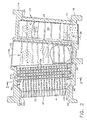
- Figure 1 is an isometric view of a portion of an annular turbine nozzle in accordance with an exemplary embodiment of the present invention.
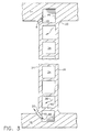
- Figure 2 is an axial sectional view through one of the vanes illustrated in Figure 1.
- Figure 3 is a radial sectional view through the vane illustrated in Figure 2 and taken along line 3-3.
-
- Illustrated in Figure 1 is a portion of an axisymmetrical first
stage turbine nozzle 10 of a high pressure turbine disposed directly downstream from a combustor (not shown) of a turbofan aircraft gas turbine engine. During operation,hot combustion gases 12 are discharged from the combustor and channeled through thenozzle 10 which directs the gases between turbine rotor blades (not shown) extending outwardly from the perimeter of the rotor disk being powered thereby. - The nozzle includes arcuate outer and
inner bands hollow vanes 18 at correspondingarcuate fillets 20 therebetween. Preferably, a single vane is integrally cast at opposite root ends thereof with corresponding portions of the outer and inner bands in a unitary singlet. Twosinglet vanes 18 are then brazed together at correspondingaxial splitlines 22 to form an integrated two-vane nozzle segment. The segments are conventionally joined together in a full segmented ring to define the annular nozzle. - The vanes are spaced circumferentially apart from each other and extend radially between the bands. Each vane has radially outer and inner roots at opposite ends thereof at which the
fillets 20 are exposed to the hot combustion gases during operation. - As shown in Figure 1, each of the
vanes 18 has an airfoil profile with a first orpressure sidewall 24, which is generally concave, and a second orsuction sidewall 26, which is generally convex, joined together at chordally opposite leading andtrailing edges - As shown in Figures 1 and 2, each vane includes a row of
trailing edge apertures 32, and cooperating inboard axial channels orslots 34 extending inside the trailing edge region of the vane in flow communication with amid-chord cavity 36. Theinboard slots 34 are disposed radially inboard between bothbands - The outer and inner vane roots are imperforate or solid between the
trailing edge 30 and themid-chord cavity 36 except for an outer inlet for themid-chord cavity 36 which extends through the outer root and outer band for receiving pressurizedcooling air 38 bled from the compressor (not shown) of the engine. - As shown in Figure 2, the
internal inboard slots 34 are defined by corresponding radially spaced apartaxial ribs 40 which bridge the opposite sidewalls of the vane. The inboard slots extend in a radial row and have corresponding inlets at themid-chord cavity 36 for receiving the cooling air therefrom which is then channeled axially aft through the trailing edge region of the vane for discharge through the correspondingtrailing edge apertures 32. - The
cavity 36 may include radially spaced apart stand-off ribs extending axially for centering a conventionalperforate impingement baffle 42. The individualinboard slots 34 include chordally spaced apart turbulators extending radially for enhancing internal cooling of the vane from the spent impingement air discharged from the mid-chord cavity. - Turbulators are conventional, and are configured as elongate ribs which extend partly inwardly from the inner surfaces of the vane for tripping the cooling air as it flows thereover. In this way, the
mid-chord cavity 36 and the array ofinboard slots 34 provide effective internal cooling of the vane from its mid-chord region down to the trailing edge from which the cooling air is discharged through thetrailing edge apertures 32. - As shown in Figure 1, both sidewalls of the vane may include conventional
film cooling holes 44 extending therethrough in flow communication with themid-chord cavity 36 andinboard slots 34, for example, for discharging the cooling air therefrom to create protective films of cooling air over the exposed outer surface of the vane. - As initially shown in Figure 1, the
trailing edge apertures 32 are spaced inboard from the inner surfaces of the two bands and away from thefillets 20. Figure 2 illustrates in more detail that each vane includes a pair of trailing edge terminal orlast apertures 32a which are the outboard-most ones thereof directly adjacent to the outer and inner bands, respectively, and thecorresponding fillets 20 thereat. - In accordance with a preferred embodiment of the present invention as illustrated in Figure 2, each vane further includes a pair of outboard channels or
slots 46 cooperating with respective ones of the lasttrailing edge apertures 32a at respective opposite root ends of each vane for backside cooling thefillets 20 at both the outer and inner bands. Theoutboard slots 46 are similar to theinboard slots 34 and extend axially in flow communication between the respectivelast apertures 32a and thecommon mid-chord cavity 36. - The
outboard slots 46 extend at least in part through the otherwise solid vane roots below the exposed inner surfaces of the bands and behind thecorresponding fillets 20 illustrated in phantom line in Figure 2. In this way, thecooling air 38 from themid-chord cavity 36 may be channeled directly behind the fillets in the thin trailing edge region of the vane for discharge from thelast apertures 32a. The fillet in this local area is therefore additionally cooled for reducing or preventing oxidation thereof and further improving the useful life of the turbine nozzle. - As shown in Figure 3, the
vane sidewalls outboard slots 46 at opposite root ends thereof extend between both sidewalls for backside cooling thecorresponding fillets 20 along both sidewalls near the vane trailing edge. - As shown in Figure 2, both
outboard slots 46 preferably extend substantially straight from themid-chord cavity 36 toward thetrailing edge 30 and locally bend or jog at the aft ends thereof to cross behind thecorresponding fillets 20 to terminate at the respective lasttrailing edge apertures 32a. In this way, the fillet is backside cooled from the mid-chord cavity aft to thetrailing edge apertures 32a with the cooling air then being discharged therefrom. - In the exemplary embodiment illustrated in Figure 1, the
trailing edge apertures 32 are located slightly forward of the trailing edge itself and breach the pressure side of the vane, with the suction side of the vane remaining imperforate. This trailing edge region of the vane is aerodynamically thin, and theoutboard slots 46 provide effective backside cooling of the fillets as the cooling air is channeled therethrough and discharged from the last apertures. - As shown in Figure 2, the array or bank of
inboard slots 34 channels cooling air axially aft from themid-chord cavity 36 for discharge from respective ones of thetrailing edge apertures 32 for cooling the thin trailing edge region of each vane radially between the two bands. The pair ofoutboard slots 46 are similarly disposed in axial flow communication between themid-chord cavity 36 and respective ones of the lasttrailing edge apertures 32a for providing additional cooling into the corresponding vane roots behind respective portions of thefillets 20. - As indicated above, the last
trailing edge apertures 32a are suitably spaced away from thefillets 20 at the corresponding outer and inner bands. Accordingly, each of theoutboard slots 46 preferably terminates in common with an adjacent or outboard last one of theinboard slots 34 at a respective ones of thelast apertures 32a. In this way, the cooling air channeled through eachoutboard slot 46 joins air channeled through the adjoininginboard slot 34 for discharge through the commonlast aperture 32a. - However, each trailing
edge aperture last aperture 32a may accordingly be limited by stress limits imposed on the vane and may be insufficient for discharging air from both its dedicatedinboard slot 34 and the additionaloutboard slot 46. - Accordingly, each of the
vanes 18 may further include one or more side apertures oroutlets 48 extending through one or bothsidewalls outboard slots 46 for additionally discharging the cooling air therefrom. - As shown in Figure 3, the
side outlets 48 preferably begin in each of theoutboard slots 46 below thefillets 20 on thepressure sidewall 24, and exit the sidewall away from the correspondingfillets 20 to directly cool the fillets. Theside outlets 48 may be disposed through both vane sidewalls 24,26 at both outer and inner bands, if required, although the side outlets are preferably used solely in the pressure sidewall to minimize nozzle efficiency losses, which would be greater on the suction sidewall. - Each
fillet 20 may therefore be backside cooled from theoutboard slot 46 recessed into the bands; internally cooled through theside outlets 48; and film cooled by the air discharged from the side outlets. - The number and specific location of the
side outlets 48 may be determined for each design application for ensuring suitable flow rate through theoutboard slots 46 for enhancing fillet cooling thereat. In the preferred embodiment illustrated in Figure 2, theside outlets 48 are disposed in pairs at each fillet along each sidewall. The outlets are chordally spaced apart from each other to provide more continuous film cooling along the trailing edge portion of the fillet. - As illustrated in Figure 2, the
turbine nozzle 10 may be made by initially forming thevanes 18 and outer and inner band segments in a conventional manner such as by casting. All of the internal features of theindividual vanes 18 may be formed by suitably casting thevanes 18 to include themid-chord cavity 36 with its outer band inlet, and the cooperatingaxial slots edge apertures 32. - In a typical first stage, high pressure turbine nozzle configuration each
vane 18 preferably also includes a radially extending forwardcavity 50 having a bottom inlet through theinner band 16 which receives the coolingair 38. Theouter band 14 is solid or imperforate at theforward cavity 50. And, theforward cavity 50 and themid-chord cavity 36, which is aft relative to the forward cavity, are separated from each other by an integral imperforate bridge extending between the two sides of the vane for providing independent cooling circuits. Theforward cavity 50 is configured in any conventional manner, including anotherimpingement baffle 42, for cooling the leading edge portion of each vane, with the cooling air being discharged through various rows of additional film cooling holes 44 in a conventional manner. - Accordingly, the
vane 18 illustrated in Figure 2 may be initially cast for forming all the desired internal cooling features thereof including the inboard andoutboard slots edge apertures side outlets 48, if used, may then be suitably drilled through the cast vanes in any conventional manner. - The resulting
turbine nozzle 10 illustrated in Figure 1 then enjoys all of the advantages of the original turbine nozzle, but now includes the additional outboard slots therein for improving backside cooling of thefillets 20 between themid-chord cavity 36 and the trailing edge apertures. The resulting turbine nozzle therefore will enjoy improved useful life and durability due to reduction or elimination of fillet oxidation in this region. - For the sake of good order, various aspects of the invention are set out in the following clauses:-
- 1. A
turbine nozzle 10 comprising: - outer and
inner bands vanes 18 at correspondingfillets 20 therebetween; and - each of said vanes includes a last
trailing edge aperture 32a spaced inboard from said fillet and disposed in flow communication with anoutboard slot 46 extending behind said fillet for channeling coolingair 38 from amid-chord cavity 36 of said vane to saidlast aperture 32a for backside cooling said fillet therealong. - 2. A nozzle according to clause 1 wherein each of said
vanes 18 further comprisesopposite sidewalls edges outboard slot 46 extends between said sidewalls for backside cooling said fillets along both said sidewalls near said trailingedge 30. - 3. A nozzle according to clause 2 wherein said
outboard slot 46 extends substantially straight from said mid-chord cavity toward said trailingedge 30, and bends at an aft end thereof to cross behind said fillet to terminate at saidlast aperture 32a. - 4. A nozzle according to
clause 3 wherein each of saidvanes 18 includes a pair of said lasttrailing edge apertures 32a and cooperating pair ofoutboard slots 46 at respective opposite root ends thereof for backside cooling said fillets at both said outer andinner bands - 5. A nozzle according to clause 4 wherein each of said
vanes 18 further comprises: - a row of trailing
edge apertures 32, including said pair oflast apertures 32a adjacent said outer andinner bands - an array of
inboard slots 34 disposed between said pair ofoutboard slots 46 in flow communication between said mid-chord cavity and respective ones of said trailingedge apertures 32. - 6. A nozzle according to clause 5 wherein each of said
outboard slots 46 terminates in common with an adjacent one of saidinboard slots 34 at a respective one of saidlast apertures 32a. - 7. A nozzle according to clause 6 wherein each of said
vanes 18 further comprises aside outlet 48 extending through one of said sidewalls 24,26 in flow communication with a respective one of saidoutboard slots 46 for discharging said cooling air therefrom. - 8. A nozzle according to clause 7 wherein said
side outlet 48 extends through one of saidfillets 20. - 9. A nozzle according to clause 8 wherein respective ones of said
side outlets 48 are disposed through bothsidewalls - 10. A nozzle according to clause 9 further comprising a pair of said side outlets extending through each of said fillets along each of said sidewalls.
- 11. A nozzle according to clause 9 wherein each of said vanes is an integral casting with corresponding portions of said bands in a unitary singlet, and two of said vane singlets are brazed together at said bands.
- 12. A nozzle according to
clause 11 wherein said outer and inner bands are imperforate at said outboard slots. - 13. A nozzle vane singlet comprising a
hollow vane 18 integrally cast at opposite ends thereof with outer andinner bands vane 18 includes a row of trailingedge apertures 32 and cooperatinginboard slots 34 joined in flow communication with amid-chord cavity 36, and a pair ofoutboard slots 46 spaced outwardly from respective last ones of said inboard slots at opposite ends of said vane and outboard of respective last ones of said trailingedge apertures 32a. - 14. A vane singlet according to clause 13 wherein each of said
outboard slots 46 terminates in common with an adjacent one of saidinboard slots 34 at a respective one of saidlast apertures 32a. - 15. A vane singlet according to
clause 14 wherein said vane further comprisesopposite sidewalls edges outboard slot 46 extends between said sidewalls for backside cooling both said sidewalls near said trailingedge 30. - 16. A vane singlet according to clause 15 wherein said
outboard slots 46 extend substantially straight from saidmid-chord cavity 36 toward said trailingedge 30, and bend at aft ends thereof to cross over to said last inboard slots at said trailing edge. - 17. A vane singlet according to
clause 16 further comprising aside outlet 48 extending through one of said sidewalls 24,26 in flow communication with a respective one of saidoutboard slots 46 for discharging cooling air therefrom. - 18. A vane singlet according to clause 17 wherein said vane joins said outer and inner bands at respective fillets, and said side outlet extends through one of said fillets.
- 19. A vane singlet according to
clause 18 further comprising a pair of said side outlets extending along said one sidewall. -
Claims (10)
- A turbine nozzle (10) comprising:outer and inner bands (14, 16) integrally cast to a pair of vanes (18) at corresponding fillets (20) therebetween; andeach of said vanes includes a last trailing edge aperture (32a) spaced inboard from said fillet and disposed in flow communication with an outboard slot (46) extending behind said fillet for channeling cooling air (38) from a mid-chord cavity (36) of said vane to said last aperture (32a) for backside cooling said fillet therealong.
- A nozzle according to claim 1 wherein each of said vanes (18) further comprises opposite sidewalls (24, 26) joined together at opposite leading and trailing edges (28, 30); and said outboard slot (46) extends between said sidewalls for backside cooling said fillets along both said sidewalls near said trailing edge (30).
- A nozzle according to claim 1 or 2 wherein said outboard slot (46) extends substantially straight from said mid-chord cavity (36) toward said trailing edge (30), and bends at an aft end thereof to cross behind said fillet to terminate at said last aperture (32a).
- A nozzle according to any preceding claim wherein each of said vanes (18) includes a pair of said last trailing edge apertures (32a) and cooperating pair of outboard slots (46) at respective opposite root ends thereof for backside cooling said fillets at both said outer and inner bands (14, 16).
- A nozzle according to claim 4 wherein each of said vanes (18) further comprises:a row of trailing edge apertures (32), including said pair of last apertures 32a adjacent said outer and inner bands (14,16) ; andan array of inboard slots (34) disposed between said pair of outboard slots (46) in flow communication between said mid-chord cavity and respective ones of said trailing edge apertures (32).
- A nozzle vane singlet comprising a hollow vane (18) integrally cast at opposite ends thereof with outer and inner bands (14, 16), and said vane (18) includes a row of trailing edge apertures (32) and cooperating inboard slots (34) joined in flow communication with a mid-chord cavity (36), and a pair of outboard slots (46) spaced outwardly from respective last ones of said inboard slots at opposite ends of said vane and outboard of respective last ones of said trailing edge apertures (32a).
- A vane singlet according to claim 6 wherein each of said outboard slots (46) terminates in common with an adjacent one of said inboard slots (34) at a respective one of said last apertures (32a).
- A vane singlet according to claim 6 or 7 wherein said vane further comprises opposite sidewalls (24, 26) joined together at opposite leading and trailing edges (28, 30); and said outboard slot (46) extends between said sidewalls for backside cooling both said sidewalls near said trailing edge (30).
- A vane singlet according to claim 6, 7 or 8 wherein said outboard slots (46) extend substantially straight from said mid-chord cavity (36) toward said trailing edge (30), and bend at aft ends thereof to cross over to said last inboard slots at said trailing edge.
- A vane singlet according to claim 8 or claim 9 when appendant to claim 8 further comprising a side outlet (48) extending through one of said sidewalls (24, 26) in flow communication with a respective one of said outboard slots (46) for discharging cooling air therefrom.
Applications Claiming Priority (2)
| Application Number | Priority Date | Filing Date | Title |
|---|---|---|---|
| US09/764,637 US6382908B1 (en) | 2001-01-18 | 2001-01-18 | Nozzle fillet backside cooling |
| US764637 | 2001-01-18 |
Publications (3)
| Publication Number | Publication Date |
|---|---|
| EP1225304A2 true EP1225304A2 (en) | 2002-07-24 |
| EP1225304A3 EP1225304A3 (en) | 2004-01-07 |
| EP1225304B1 EP1225304B1 (en) | 2007-06-13 |
Family
ID=25071310
Family Applications (1)
| Application Number | Title | Priority Date | Filing Date |
|---|---|---|---|
| EP02250269A Expired - Lifetime EP1225304B1 (en) | 2001-01-18 | 2002-01-15 | Nozzle fillet backside cooling |
Country Status (4)
| Country | Link |
|---|---|
| US (1) | US6382908B1 (en) |
| EP (1) | EP1225304B1 (en) |
| JP (1) | JP4100916B2 (en) |
| DE (1) | DE60220556T2 (en) |
Families Citing this family (22)
| Publication number | Priority date | Publication date | Assignee | Title |
|---|---|---|---|---|
| GB2391046B (en) * | 2002-07-18 | 2007-02-14 | Rolls Royce Plc | Aerofoil |
| GB2395987B (en) * | 2002-12-02 | 2005-12-21 | Alstom | Turbine blade with cooling bores |
| US6830432B1 (en) * | 2003-06-24 | 2004-12-14 | Siemens Westinghouse Power Corporation | Cooling of combustion turbine airfoil fillets |
| DE10346366A1 (en) * | 2003-09-29 | 2005-04-28 | Rolls Royce Deutschland | Turbine blade for an aircraft engine and casting mold for the production thereof |
| US20050135923A1 (en) * | 2003-12-22 | 2005-06-23 | Todd Coons | Cooled vane cluster |
| US7334306B2 (en) * | 2004-06-02 | 2008-02-26 | General Electric Company | Methods and apparatus for fabricating a turbine nozzle assembly |
| US7220103B2 (en) * | 2004-10-18 | 2007-05-22 | United Technologies Corporation | Impingement cooling of large fillet of an airfoil |
| US7296966B2 (en) * | 2004-12-20 | 2007-11-20 | General Electric Company | Methods and apparatus for assembling gas turbine engines |
| US7841828B2 (en) * | 2006-10-05 | 2010-11-30 | Siemens Energy, Inc. | Turbine airfoil with submerged endwall cooling channel |
| US7722326B2 (en) * | 2007-03-13 | 2010-05-25 | Siemens Energy, Inc. | Intensively cooled trailing edge of thin airfoils for turbine engines |
| US7775769B1 (en) | 2007-05-24 | 2010-08-17 | Florida Turbine Technologies, Inc. | Turbine airfoil fillet region cooling |
| US8393867B2 (en) * | 2008-03-31 | 2013-03-12 | United Technologies Corporation | Chambered airfoil cooling |
| US8133015B2 (en) * | 2008-09-30 | 2012-03-13 | General Electric Company | Turbine nozzle for a gas turbine engine |
| EP2333240B1 (en) * | 2009-12-03 | 2013-02-13 | Alstom Technology Ltd | Two-part turbine blade with improved cooling and vibrational characteristics |
| US9322279B2 (en) * | 2012-07-02 | 2016-04-26 | United Technologies Corporation | Airfoil cooling arrangement |
| US9156114B2 (en) | 2012-11-13 | 2015-10-13 | General Electric Company | Method for manufacturing turbine nozzle having non-linear cooling conduit |
| US9200534B2 (en) | 2012-11-13 | 2015-12-01 | General Electric Company | Turbine nozzle having non-linear cooling conduit |
| US10494939B2 (en) | 2014-02-13 | 2019-12-03 | United Technologies Corporation | Air shredder insert |
| US10012092B2 (en) * | 2015-08-12 | 2018-07-03 | United Technologies Corporation | Low turn loss baffle flow diverter |
| US10190422B2 (en) | 2016-04-12 | 2019-01-29 | Solar Turbines Incorporated | Rotation enhanced turbine blade cooling |
| FR3094743B1 (en) * | 2019-04-03 | 2021-05-14 | Safran Aircraft Engines | Improved vane for turbomachine |
| US11608754B2 (en) | 2021-07-14 | 2023-03-21 | Doosan Enerbility Co., Ltd. | Turbine nozzle assembly and gas turbine including the same |
Citations (3)
| Publication number | Priority date | Publication date | Assignee | Title |
|---|---|---|---|---|
| US3628885A (en) * | 1969-10-01 | 1971-12-21 | Gen Electric | Fluid-cooled airfoil |
| US5743708A (en) * | 1994-08-23 | 1998-04-28 | General Electric Co. | Turbine stator vane segments having combined air and steam cooling circuits |
| EP1221538A2 (en) * | 2001-01-05 | 2002-07-10 | General Electric Company | Cooled turbine stator blade |
Family Cites Families (2)
| Publication number | Priority date | Publication date | Assignee | Title |
|---|---|---|---|---|
| US5516260A (en) * | 1994-10-07 | 1996-05-14 | General Electric Company | Bonded turbine airfuel with floating wall cooling insert |
| US6200087B1 (en) * | 1999-05-10 | 2001-03-13 | General Electric Company | Pressure compensated turbine nozzle |
-
2001
- 2001-01-18 US US09/764,637 patent/US6382908B1/en not_active Expired - Lifetime
-
2002
- 2002-01-15 DE DE60220556T patent/DE60220556T2/en not_active Expired - Lifetime
- 2002-01-15 EP EP02250269A patent/EP1225304B1/en not_active Expired - Lifetime
- 2002-01-17 JP JP2002008110A patent/JP4100916B2/en not_active Expired - Fee Related
Patent Citations (3)
| Publication number | Priority date | Publication date | Assignee | Title |
|---|---|---|---|---|
| US3628885A (en) * | 1969-10-01 | 1971-12-21 | Gen Electric | Fluid-cooled airfoil |
| US5743708A (en) * | 1994-08-23 | 1998-04-28 | General Electric Co. | Turbine stator vane segments having combined air and steam cooling circuits |
| EP1221538A2 (en) * | 2001-01-05 | 2002-07-10 | General Electric Company | Cooled turbine stator blade |
Also Published As
| Publication number | Publication date |
|---|---|
| DE60220556D1 (en) | 2007-07-26 |
| EP1225304B1 (en) | 2007-06-13 |
| US6382908B1 (en) | 2002-05-07 |
| JP2002242610A (en) | 2002-08-28 |
| EP1225304A3 (en) | 2004-01-07 |
| DE60220556T2 (en) | 2008-02-21 |
| JP4100916B2 (en) | 2008-06-11 |
Similar Documents
| Publication | Publication Date | Title |
|---|---|---|
| US6382908B1 (en) | Nozzle fillet backside cooling | |
| EP1469164B1 (en) | Complementary cooled turbine nozzle | |
| EP1221538B1 (en) | Cooled turbine stator blade | |
| EP1284338B1 (en) | Tangential flow baffle | |
| JP4453826B2 (en) | 3-circuit turbine blade | |
| EP1205636B1 (en) | Turbine blade for a gas turbine and method of cooling said blade | |
| EP1205634B1 (en) | Turbine blade and use thereof | |
| US6354797B1 (en) | Brazeless fillet turbine nozzle | |
| EP1001137B1 (en) | Gas turbine airfoil with axial serpentine cooling circuits | |
| CA2668605C (en) | Crossflow turbine airfoil | |
| EP1526251B1 (en) | Turbine nozzle cooling configuration | |
| EP1798379B1 (en) | Countercooled turbine nozzle vane | |
| EP1586739A2 (en) | Thermal shield for a gas turbine airfoil | |
| EP1473439B1 (en) | Cooled castellated turbine airfoil | |
| EP1584790A2 (en) | Impingement cooled turbine airfoil | |
| EP1088964A2 (en) | Slotted impingement cooling of airfoil leading edge | |
| US6929446B2 (en) | Counterbalanced flow turbine nozzle | |
| EP1052373A2 (en) | Pressure compensated turbine nozzle | |
| US6439837B1 (en) | Nozzle braze backside cooling |
Legal Events
| Date | Code | Title | Description |
|---|---|---|---|
| PUAI | Public reference made under article 153(3) epc to a published international application that has entered the european phase |
Free format text: ORIGINAL CODE: 0009012 |
|
| AK | Designated contracting states |
Kind code of ref document: A2 Designated state(s): AT BE CH CY DE DK ES FI FR GB GR IE IT LI LU MC NL PT SE TR |
|
| AX | Request for extension of the european patent |
Free format text: AL;LT;LV;MK;RO;SI |
|
| RIN1 | Information on inventor provided before grant (corrected) |
Inventor name: KEITH, SEAN ROBERT Inventor name: TRESSLER, JUDD DODGE Inventor name: BRASSFIELD, STEVEN ROBERT Inventor name: HEYWARD, JOHN PETER |
|
| PUAL | Search report despatched |
Free format text: ORIGINAL CODE: 0009013 |
|
| AK | Designated contracting states |
Kind code of ref document: A3 Designated state(s): AT BE CH CY DE DK ES FI FR GB GR IE IT LI LU MC NL PT SE TR |
|
| AX | Request for extension of the european patent |
Extension state: AL LT LV MK RO SI |
|
| 17P | Request for examination filed |
Effective date: 20040707 |
|
| AKX | Designation fees paid |
Designated state(s): DE FR GB IT |
|
| GRAP | Despatch of communication of intention to grant a patent |
Free format text: ORIGINAL CODE: EPIDOSNIGR1 |
|
| GRAS | Grant fee paid |
Free format text: ORIGINAL CODE: EPIDOSNIGR3 |
|
| GRAA | (expected) grant |
Free format text: ORIGINAL CODE: 0009210 |
|
| AK | Designated contracting states |
Kind code of ref document: B1 Designated state(s): DE FR GB IT |
|
| REG | Reference to a national code |
Ref country code: GB Ref legal event code: FG4D |
|
| REF | Corresponds to: |
Ref document number: 60220556 Country of ref document: DE Date of ref document: 20070726 Kind code of ref document: P |
|
| ET | Fr: translation filed | ||
| PLBE | No opposition filed within time limit |
Free format text: ORIGINAL CODE: 0009261 |
|
| STAA | Information on the status of an ep patent application or granted ep patent |
Free format text: STATUS: NO OPPOSITION FILED WITHIN TIME LIMIT |
|
| 26N | No opposition filed |
Effective date: 20080314 |
|
| REG | Reference to a national code |
Ref country code: FR Ref legal event code: PLFP Year of fee payment: 15 |
|
| PGFP | Annual fee paid to national office [announced via postgrant information from national office to epo] |
Ref country code: IT Payment date: 20160122 Year of fee payment: 15 Ref country code: DE Payment date: 20160127 Year of fee payment: 15 |
|
| PGFP | Annual fee paid to national office [announced via postgrant information from national office to epo] |
Ref country code: GB Payment date: 20160127 Year of fee payment: 15 Ref country code: FR Payment date: 20160126 Year of fee payment: 15 |
|
| REG | Reference to a national code |
Ref country code: DE Ref legal event code: R119 Ref document number: 60220556 Country of ref document: DE |
|
| GBPC | Gb: european patent ceased through non-payment of renewal fee |
Effective date: 20170115 |
|
| REG | Reference to a national code |
Ref country code: FR Ref legal event code: ST Effective date: 20170929 |
|
| PG25 | Lapsed in a contracting state [announced via postgrant information from national office to epo] |
Ref country code: FR Free format text: LAPSE BECAUSE OF NON-PAYMENT OF DUE FEES Effective date: 20170131 |
|
| PG25 | Lapsed in a contracting state [announced via postgrant information from national office to epo] |
Ref country code: DE Free format text: LAPSE BECAUSE OF NON-PAYMENT OF DUE FEES Effective date: 20170801 Ref country code: GB Free format text: LAPSE BECAUSE OF NON-PAYMENT OF DUE FEES Effective date: 20170115 |
|
| PG25 | Lapsed in a contracting state [announced via postgrant information from national office to epo] |
Ref country code: IT Free format text: LAPSE BECAUSE OF NON-PAYMENT OF DUE FEES Effective date: 20170115 |