EP1065137A2 - Side frame reinforcement structure for vehicle - Google Patents
Side frame reinforcement structure for vehicle Download PDFInfo
- Publication number
- EP1065137A2 EP1065137A2 EP00110836A EP00110836A EP1065137A2 EP 1065137 A2 EP1065137 A2 EP 1065137A2 EP 00110836 A EP00110836 A EP 00110836A EP 00110836 A EP00110836 A EP 00110836A EP 1065137 A2 EP1065137 A2 EP 1065137A2
- Authority
- EP
- European Patent Office
- Prior art keywords
- side frame
- vehicle
- dash panel
- welded
- cowl dash
- Prior art date
- Legal status (The legal status is an assumption and is not a legal conclusion. Google has not performed a legal analysis and makes no representation as to the accuracy of the status listed.)
- Granted
Links
- 230000002787 reinforcement Effects 0.000 title claims abstract description 13
- 230000003014 reinforcing effect Effects 0.000 claims abstract description 16
- 238000003466 welding Methods 0.000 description 2
- 208000027418 Wounds and injury Diseases 0.000 description 1
- 230000006378 damage Effects 0.000 description 1
- 208000014674 injury Diseases 0.000 description 1
Images

Classifications
-
- B—PERFORMING OPERATIONS; TRANSPORTING
- B62—LAND VEHICLES FOR TRAVELLING OTHERWISE THAN ON RAILS
- B62D—MOTOR VEHICLES; TRAILERS
- B62D25/00—Superstructure or monocoque structure sub-units; Parts or details thereof not otherwise provided for
- B62D25/20—Floors or bottom sub-units
-
- B—PERFORMING OPERATIONS; TRANSPORTING
- B62—LAND VEHICLES FOR TRAVELLING OTHERWISE THAN ON RAILS
- B62D—MOTOR VEHICLES; TRAILERS
- B62D21/00—Understructures, i.e. chassis frame on which a vehicle body may be mounted
- B62D21/15—Understructures, i.e. chassis frame on which a vehicle body may be mounted having impact absorbing means, e.g. a frame designed to permanently or temporarily change shape or dimension upon impact with another body
- B62D21/152—Front or rear frames
-
- B—PERFORMING OPERATIONS; TRANSPORTING
- B62—LAND VEHICLES FOR TRAVELLING OTHERWISE THAN ON RAILS
- B62D—MOTOR VEHICLES; TRAILERS
- B62D25/00—Superstructure or monocoque structure sub-units; Parts or details thereof not otherwise provided for
- B62D25/08—Front or rear portions
- B62D25/081—Cowls
Definitions
- the present invention relates to a side frame reinforcement structure for a vehicle, and more particularly, the present invention relates to a side frame reinforcement structure for a vehicle, which increases rigidity of a welding portion where a cowl dash panel and a side frame forming a side of the vehicle are coupled with each other, thereby minimizing, upon collision, deformation of the side frame and the cowl dash panel and ensuring safety of a passenger.
- cowl dash panel Between an engine room which is defined at a front part of a vehicle and a passenger compartment, there is disposed a cowl dash panel.
- a pair of side frames which are respectively located at both front sides of the vehicle, are welded to both left and right ends of the cowl dash panel, respectively.
- an object of the present invention is to provide a side frame reinforcement structure for a vehicle, which increases rigidity of a connecting portion between a cowl dash panel and a side frame, thereby ensuring, upon collision, safety of a passenger seated inside a passenger compartment.
- a side frame reinforcement structure for a vehicle characterized by: a reinforcing member bent in a multi-stepwise manner, the reinforcing member having a lower end which is welded onto an upper surface of a cowl dash panel adjacent an end of the cowl dash panel and an upper end which is welded to a side frame which in turn is welded to the end of the cowl dash panel, the reinforcing member cooperating with the cowl dash panel and the side frame thereby to define a closed space.
- a side frame reinforcement structure for a vehicle in accordance with an embodiment of the present invention includes a reinforcing member 30.
- the reinforcing member 30 possesses a configuration which is bent in a multi-stepwise manner.
- the reinforcing member 30 has a lower end which is welded onto an upper surface of a cowl dash panel 10 adjacent to an end of the cowl dash panel 10 and an upper end which is welded to a side frame 20 (corresponding to a front pillar) which in turn is welded to the end of the cowl dash panel 10.
- the reinforcing member 30 cooperates with the cowl dash panel 10 and the side frame 20, thereby to define a closed space.
- the reinforcing member 30 which is bent in a multi-stepwise manner, is welded to the cowl dash panel 10 and the side frame 20, respectively, adjacent to a welding portion between the cowl dash panel 10 and the side frame 20 while defining the closed space in cooperation with the cowl dash panel 10 and the side frame 20, if collision occurs when the vehicle runs on the road and thereby impact is exerted to the vehicle from a front of the vehicle, because the reinforcing member 30 generates, while being supported by the side frame 20, supporting force acting in a direction toward the front of the vehicle which is opposite to a direction along which the impact is exerted to the vehicle, the impact is effectively absorbed and deformation of the side frame 20 is minimized.
- impact energy is primarily absorbed by the side frame 20
- the impact energy which remains after being absorbed by the side frame 20 is secondarily absorbed by the closed space which is defined due to the fact that the reinforcing member 30 is welded to the cowl dash panel 10 and the side frame 20.
- the impact energy which still remains after being absorbed by the closed space is absorbed by the cowl dash panel 10 in a state wherein it is distributed over a wide area.
- the side frame reinforcement structure for a vehicle according to the present invention provides advantages in that, when collision occurs while a vehicle runs on the road and thereby impact is exerted to the vehicle from a widthwise direction or a lengthwise direction of the vehicle, a side frame which forms a side of the vehicle, is prevented from being deformed and from being pushed toward a passenger compartment, whereby safety of a passenger seated inside the passenger compartment is assured.
Landscapes
- Engineering & Computer Science (AREA)
- Chemical & Material Sciences (AREA)
- Combustion & Propulsion (AREA)
- Transportation (AREA)
- Mechanical Engineering (AREA)
- Body Structure For Vehicles (AREA)
- Superstructure Of Vehicle (AREA)
Abstract
Description
- The present invention relates to a side frame reinforcement structure for a vehicle, and more particularly, the present invention relates to a side frame reinforcement structure for a vehicle, which increases rigidity of a welding portion where a cowl dash panel and a side frame forming a side of the vehicle are coupled with each other, thereby minimizing, upon collision, deformation of the side frame and the cowl dash panel and ensuring safety of a passenger.
- Generally, between an engine room which is defined at a front part of a vehicle and a passenger compartment, there is disposed a cowl dash panel. A pair of side frames which are respectively located at both front sides of the vehicle, are welded to both left and right ends of the cowl dash panel, respectively.
- However, in the conventional art, as can be readily seen from FIG. 1, because a pair of
side frames 20 are arranged in a manner such that they are simply welded to both left and right ends of acowl dash panel 10, respectively, in the case that a head-on collision occurs at a point which is deviated from a center of a vehicle while the vehicle runs on the road, theside frame 20 is likely to be deformed. Therefore, as theside frame 20 which is deformed by the head-on collision is pushed toward a passenger compartment, injury potential to a passenger seated inside the passenger compartment cannot but be increased. - Accordingly, the present invention has been made in an effort to solve the problems occurring in the related art, and an object of the present invention is to provide a side frame reinforcement structure for a vehicle, which increases rigidity of a connecting portion between a cowl dash panel and a side frame, thereby ensuring, upon collision, safety of a passenger seated inside a passenger compartment.
- In order to achieve the above object, according to the present invention, there is provided a side frame reinforcement structure for a vehicle, characterized by: a reinforcing member bent in a multi-stepwise manner, the reinforcing member having a lower end which is welded onto an upper surface of a cowl dash panel adjacent an end of the cowl dash panel and an upper end which is welded to a side frame which in turn is welded to the end of the cowl dash panel, the reinforcing member cooperating with the cowl dash panel and the side frame thereby to define a closed space.
- The above objects, and other features and advantages of the present invention will become more apparent after a reading of the following detailed description when taken in conjunction with the drawings, in which:
- FIG. 1 is a schematic side view illustrating a state wherein a side frame is welded to an end of a cowl dash panel;
- FIG. 2 is an exploded perspective view illustrating a side frame reinforcement structure for a vehicle in accordance with an embodiment of the present invention, which is not welded to a cowl dash panel and a side frame; and
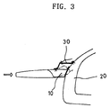
- FIG. 3 is a schematic side view similar to FIG. 1, illustrating another state wherein the side frame reinforcement structure according to the present invention is welded to the cowl dash panel and the side frame.
-
- Reference will now be made in greater detail to a preferred embodiment of the invention, an example of which is illustrated in the accompanying drawings. Wherever possible, the same reference numerals will be used throughout the drawings and the description to refer to the same or like parts.
- As shown in FIGs. 2 and 3, a side frame reinforcement structure for a vehicle, in accordance with an embodiment of the present invention includes a reinforcing
member 30. The reinforcingmember 30 possesses a configuration which is bent in a multi-stepwise manner. The reinforcingmember 30 has a lower end which is welded onto an upper surface of acowl dash panel 10 adjacent to an end of thecowl dash panel 10 and an upper end which is welded to a side frame 20 (corresponding to a front pillar) which in turn is welded to the end of thecowl dash panel 10. The reinforcingmember 30 cooperates with thecowl dash panel 10 and theside frame 20, thereby to define a closed space. - In the side frame reinforcement structure for a vehicle, constructed as mentioned above, by the fact that the reinforcing
member 30 which is bent in a multi-stepwise manner, is welded to thecowl dash panel 10 and theside frame 20, respectively, adjacent to a welding portion between thecowl dash panel 10 and theside frame 20 while defining the closed space in cooperation with thecowl dash panel 10 and theside frame 20, if collision occurs when the vehicle runs on the road and thereby impact is exerted to the vehicle from a front of the vehicle, because the reinforcingmember 30 generates, while being supported by theside frame 20, supporting force acting in a direction toward the front of the vehicle which is opposite to a direction along which the impact is exerted to the vehicle, the impact is effectively absorbed and deformation of theside frame 20 is minimized. - Also, in the case that impact is exerted to the vehicle from a side of the vehicle, impact energy is primarily absorbed by the
side frame 20, and the impact energy which remains after being absorbed by theside frame 20 is secondarily absorbed by the closed space which is defined due to the fact that the reinforcingmember 30 is welded to thecowl dash panel 10 and theside frame 20. Finally, the impact energy which still remains after being absorbed by the closed space, is absorbed by thecowl dash panel 10 in a state wherein it is distributed over a wide area. - As described above, the side frame reinforcement structure for a vehicle according to the present invention, constructed as mentioned above, provides advantages in that, when collision occurs while a vehicle runs on the road and thereby impact is exerted to the vehicle from a widthwise direction or a lengthwise direction of the vehicle, a side frame which forms a side of the vehicle, is prevented from being deformed and from being pushed toward a passenger compartment, whereby safety of a passenger seated inside the passenger compartment is assured.
- In the drawings and specification, there have been disclosed typical preferred embodiments of the invention and, although specific terms are employed, they are used in a generic and descriptive sense only and not for purposes of limitation, the scope of the invention being set forth in the following claims.
Claims (1)
- A side frame reinforcement structure for a vehicle, characterized by:a reinforcing member (30) bent in a multi-stepwise manner, the reinforcing member (30) having a lower end which is welded onto an upper surface of a cowl dash panel (10) adjacent to an end of the cowl dash panel (10) and an upper end which is welded to a side frame (20) which in turn is welded to the end of the cowl dash panel (10), the reinforcing member (30) cooperating with the cowl dash panel (10) and the side frame (20) thereby to define a closed space.
Applications Claiming Priority (2)
| Application Number | Priority Date | Filing Date | Title |
|---|---|---|---|
| KR1019990025967A KR20010005168A (en) | 1999-06-30 | 1999-06-30 | Side frame reinforcement structure of car |
| KR9925967 | 1999-06-30 |
Publications (3)
| Publication Number | Publication Date |
|---|---|
| EP1065137A2 true EP1065137A2 (en) | 2001-01-03 |
| EP1065137A3 EP1065137A3 (en) | 2001-11-07 |
| EP1065137B1 EP1065137B1 (en) | 2003-08-06 |
Family
ID=19598035
Family Applications (1)
| Application Number | Title | Priority Date | Filing Date |
|---|---|---|---|
| EP00110836A Expired - Lifetime EP1065137B1 (en) | 1999-06-30 | 2000-05-22 | Side frame reinforcement structure for vehicle |
Country Status (4)
| Country | Link |
|---|---|
| US (1) | US6390540B1 (en) |
| EP (1) | EP1065137B1 (en) |
| KR (1) | KR20010005168A (en) |
| DE (1) | DE60004296T2 (en) |
Cited By (1)
| Publication number | Priority date | Publication date | Assignee | Title |
|---|---|---|---|---|
| US9333989B2 (en) * | 2014-06-25 | 2016-05-10 | Ford Global Technologies, Llc | Vehicle frame bracket |
Families Citing this family (2)
| Publication number | Priority date | Publication date | Assignee | Title |
|---|---|---|---|---|
| US20150001889A1 (en) * | 2013-06-28 | 2015-01-01 | GM Global Technology Operations LLC | Adaptor for a front body hinge pillar |
| JP6491927B2 (en) * | 2015-03-31 | 2019-03-27 | 株式会社Subaru | Body front structure |
Family Cites Families (7)
| Publication number | Priority date | Publication date | Assignee | Title |
|---|---|---|---|---|
| JPS521821A (en) * | 1975-06-24 | 1977-01-08 | Nissan Motor Co Ltd | Car body construction |
| JPS6017414Y2 (en) * | 1978-10-02 | 1985-05-28 | マツダ株式会社 | Joint structure of automobile front deck |
| JPS55165875U (en) * | 1979-05-16 | 1980-11-28 | ||
| US4545612A (en) * | 1981-08-26 | 1985-10-08 | Mazda Motor Corporation | Front side structure of an automobile body |
| US4699419A (en) * | 1985-07-03 | 1987-10-13 | Toyota Jidosha Kabushiki Kaisha | Structure for connecting front pillar and cowl in vehicle |
| JPS62187667A (en) * | 1986-02-13 | 1987-08-17 | Mazda Motor Corp | Front body structure for automobile |
| JPH0764278B2 (en) * | 1988-07-30 | 1995-07-12 | マツダ株式会社 | Front body structure of automobile |
-
1999
- 1999-06-30 KR KR1019990025967A patent/KR20010005168A/en not_active Ceased
-
2000
- 2000-05-22 DE DE60004296T patent/DE60004296T2/en not_active Expired - Fee Related
- 2000-05-22 EP EP00110836A patent/EP1065137B1/en not_active Expired - Lifetime
- 2000-06-13 US US09/592,675 patent/US6390540B1/en not_active Expired - Fee Related
Non-Patent Citations (1)
| Title |
|---|
| None |
Cited By (1)
| Publication number | Priority date | Publication date | Assignee | Title |
|---|---|---|---|---|
| US9333989B2 (en) * | 2014-06-25 | 2016-05-10 | Ford Global Technologies, Llc | Vehicle frame bracket |
Also Published As
| Publication number | Publication date |
|---|---|
| EP1065137B1 (en) | 2003-08-06 |
| US6390540B1 (en) | 2002-05-21 |
| DE60004296T2 (en) | 2004-06-09 |
| KR20010005168A (en) | 2001-01-15 |
| EP1065137A3 (en) | 2001-11-07 |
| DE60004296D1 (en) | 2003-09-11 |
Similar Documents
| Publication | Publication Date | Title |
|---|---|---|
| JP3117840B2 (en) | Body side structure | |
| EP0990577B1 (en) | Front body structure of vehicle | |
| US7731272B2 (en) | A-pillar force transfer structure | |
| EP0921051A2 (en) | Front portion structure of vehicle frame | |
| JPH0725236A (en) | Vehicle door structure | |
| US4822096A (en) | Front frame structure for vehicle | |
| CN111284564A (en) | Vehicle body structure | |
| JPH0930452A (en) | Side sill reinforcement structure for automobiles | |
| EP1787895B1 (en) | Rear vehicle body structure | |
| EP0908372B1 (en) | Construction of root portion of front side member | |
| US6390540B1 (en) | Side frame reinforcement structure for vehicle | |
| JP3646583B2 (en) | Front side member structure | |
| JP3322374B2 (en) | Car hood structure | |
| KR100339221B1 (en) | Car body reinforcement structure of vehicle | |
| JPH05294257A (en) | Front body structure of automobile | |
| JPH09164975A (en) | Front part car body structure of cab-over type vehicle | |
| JP2852244B2 (en) | Lower body structure of vehicle | |
| JPH061129U (en) | Vehicle frame structure | |
| KR20030088778A (en) | Rear pillar part combination structure of SUV | |
| KR930008315Y1 (en) | Front side member of car | |
| JPH08282537A (en) | Vehicle dash cross structure | |
| KR0135440B1 (en) | A center pillar assembly | |
| KR200205045Y1 (en) | Rear body structure of car | |
| JPH0624310Y2 (en) | Front body structure of automobile | |
| KR100392088B1 (en) | A reinforcement panel of front door hinge in car |
Legal Events
| Date | Code | Title | Description |
|---|---|---|---|
| PUAI | Public reference made under article 153(3) epc to a published international application that has entered the european phase |
Free format text: ORIGINAL CODE: 0009012 |
|
| AK | Designated contracting states |
Kind code of ref document: A2 Designated state(s): DE FR IT Kind code of ref document: A2 Designated state(s): AT BE CH CY DE DK ES FI FR GB GR IE IT LI LU MC NL PT SE |
|
| AX | Request for extension of the european patent |
Free format text: AL;LT;LV;MK;RO;SI |
|
| PUAL | Search report despatched |
Free format text: ORIGINAL CODE: 0009013 |
|
| AK | Designated contracting states |
Kind code of ref document: A3 Designated state(s): AT BE CH CY DE DK ES FI FR GB GR IE IT LI LU MC NL PT SE |
|
| AX | Request for extension of the european patent |
Free format text: AL;LT;LV;MK;RO;SI |
|
| 17P | Request for examination filed |
Effective date: 20020507 |
|
| AKX | Designation fees paid |
Free format text: DE FR IT |
|
| 17Q | First examination report despatched |
Effective date: 20020626 |
|
| RAP1 | Party data changed (applicant data changed or rights of an application transferred) |
Owner name: KIA MOTORS CORPORATION |
|
| GRAH | Despatch of communication of intention to grant a patent |
Free format text: ORIGINAL CODE: EPIDOS IGRA |
|
| GRAH | Despatch of communication of intention to grant a patent |
Free format text: ORIGINAL CODE: EPIDOS IGRA |
|
| RIN1 | Information on inventor provided before grant (corrected) |
Inventor name: YANG, CHUL-HO |
|
| GRAA | (expected) grant |
Free format text: ORIGINAL CODE: 0009210 |
|
| AK | Designated contracting states |
Designated state(s): DE FR IT |
|
| REF | Corresponds to: |
Ref document number: 60004296 Country of ref document: DE Date of ref document: 20030911 Kind code of ref document: P |
|
| PGFP | Annual fee paid to national office [announced via postgrant information from national office to epo] |
Ref country code: FR Payment date: 20040510 Year of fee payment: 5 |
|
| ET | Fr: translation filed | ||
| PLBE | No opposition filed within time limit |
Free format text: ORIGINAL CODE: 0009261 |
|
| STAA | Information on the status of an ep patent application or granted ep patent |
Free format text: STATUS: NO OPPOSITION FILED WITHIN TIME LIMIT |
|
| 26N | No opposition filed |
Effective date: 20040507 |
|
| PG25 | Lapsed in a contracting state [announced via postgrant information from national office to epo] |
Ref country code: IT Free format text: LAPSE BECAUSE OF NON-PAYMENT OF DUE FEES Effective date: 20050522 |
|
| PG25 | Lapsed in a contracting state [announced via postgrant information from national office to epo] |
Ref country code: FR Free format text: LAPSE BECAUSE OF NON-PAYMENT OF DUE FEES Effective date: 20060131 |
|
| REG | Reference to a national code |
Ref country code: FR Ref legal event code: ST Effective date: 20060131 |
|
| PGFP | Annual fee paid to national office [announced via postgrant information from national office to epo] |
Ref country code: DE Payment date: 20080529 Year of fee payment: 9 |
|
| PG25 | Lapsed in a contracting state [announced via postgrant information from national office to epo] |
Ref country code: DE Free format text: LAPSE BECAUSE OF NON-PAYMENT OF DUE FEES Effective date: 20091201 |