EP1065108A2 - Structure of the front of a vehicle body - Google Patents
Structure of the front of a vehicle body Download PDFInfo
- Publication number
- EP1065108A2 EP1065108A2 EP00112533A EP00112533A EP1065108A2 EP 1065108 A2 EP1065108 A2 EP 1065108A2 EP 00112533 A EP00112533 A EP 00112533A EP 00112533 A EP00112533 A EP 00112533A EP 1065108 A2 EP1065108 A2 EP 1065108A2
- Authority
- EP
- European Patent Office
- Prior art keywords
- vehicle body
- vehicle
- bumper
- projecting part
- energy
- Prior art date
- Legal status (The legal status is an assumption and is not a legal conclusion. Google has not performed a legal analysis and makes no representation as to the accuracy of the status listed.)
- Granted
Links
- 230000002787 reinforcement Effects 0.000 claims description 54
- 229920005989 resin Polymers 0.000 claims description 37
- 239000011347 resin Substances 0.000 claims description 37
- 238000013017 mechanical damping Methods 0.000 claims description 3
- 210000002414 leg Anatomy 0.000 abstract description 51
- 210000003127 knee Anatomy 0.000 abstract description 20
- 239000006096 absorbing agent Substances 0.000 description 112
- 230000000694 effects Effects 0.000 description 35
- 239000004743 Polypropylene Substances 0.000 description 18
- 229920001155 polypropylene Polymers 0.000 description 18
- 238000010276 construction Methods 0.000 description 14
- 239000002184 metal Substances 0.000 description 13
- 229910052751 metal Inorganic materials 0.000 description 13
- -1 polypropylene Polymers 0.000 description 13
- XEEYBQQBJWHFJM-UHFFFAOYSA-N Iron Chemical compound [Fe] XEEYBQQBJWHFJM-UHFFFAOYSA-N 0.000 description 10
- 229920003002 synthetic resin Polymers 0.000 description 9
- 239000000057 synthetic resin Substances 0.000 description 9
- 239000004698 Polyethylene Substances 0.000 description 8
- 229920000573 polyethylene Polymers 0.000 description 8
- 230000007257 malfunction Effects 0.000 description 7
- 230000000712 assembly Effects 0.000 description 6
- 238000000429 assembly Methods 0.000 description 6
- 239000000463 material Substances 0.000 description 6
- 239000006261 foam material Substances 0.000 description 5
- 229910052742 iron Inorganic materials 0.000 description 5
- 230000002093 peripheral effect Effects 0.000 description 4
- 230000002459 sustained effect Effects 0.000 description 4
- 229920006328 Styrofoam Polymers 0.000 description 3
- 238000004026 adhesive bonding Methods 0.000 description 3
- 230000003014 reinforcing effect Effects 0.000 description 3
- 239000008261 styrofoam Substances 0.000 description 3
- 238000013016 damping Methods 0.000 description 2
- 238000009826 distribution Methods 0.000 description 2
- 238000009434 installation Methods 0.000 description 2
- 238000000034 method Methods 0.000 description 2
- 238000012986 modification Methods 0.000 description 2
- 230000004048 modification Effects 0.000 description 2
- 238000010408 sweeping Methods 0.000 description 2
- 239000004677 Nylon Substances 0.000 description 1
- 239000004676 acrylonitrile butadiene styrene Substances 0.000 description 1
- 229920000122 acrylonitrile butadiene styrene Polymers 0.000 description 1
- 210000003423 ankle Anatomy 0.000 description 1
- 230000007423 decrease Effects 0.000 description 1
- 230000003247 decreasing effect Effects 0.000 description 1
- 238000010102 injection blow moulding Methods 0.000 description 1
- 238000000465 moulding Methods 0.000 description 1
- 229920001778 nylon Polymers 0.000 description 1
- 230000009467 reduction Effects 0.000 description 1
- 230000000717 retained effect Effects 0.000 description 1
- 238000010079 rubber tapping Methods 0.000 description 1
- 239000011359 shock absorbing material Substances 0.000 description 1
- 239000007787 solid Substances 0.000 description 1
- 239000000243 solution Substances 0.000 description 1
- 239000012815 thermoplastic material Substances 0.000 description 1
- 238000009827 uniform distribution Methods 0.000 description 1
- 238000003466 welding Methods 0.000 description 1
Images



















Classifications
-
- B—PERFORMING OPERATIONS; TRANSPORTING
- B60—VEHICLES IN GENERAL
- B60R—VEHICLES, VEHICLE FITTINGS, OR VEHICLE PARTS, NOT OTHERWISE PROVIDED FOR
- B60R19/00—Wheel guards; Radiator guards, e.g. grilles; Obstruction removers; Fittings damping bouncing force in collisions
-
- B—PERFORMING OPERATIONS; TRANSPORTING
- B60—VEHICLES IN GENERAL
- B60R—VEHICLES, VEHICLE FITTINGS, OR VEHICLE PARTS, NOT OTHERWISE PROVIDED FOR
- B60R19/00—Wheel guards; Radiator guards, e.g. grilles; Obstruction removers; Fittings damping bouncing force in collisions
- B60R19/02—Bumpers, i.e. impact receiving or absorbing members for protecting vehicles or fending off blows from other vehicles or objects
- B60R19/04—Bumpers, i.e. impact receiving or absorbing members for protecting vehicles or fending off blows from other vehicles or objects formed from more than one section in a side-by-side arrangement
- B60R19/12—Bumpers, i.e. impact receiving or absorbing members for protecting vehicles or fending off blows from other vehicles or objects formed from more than one section in a side-by-side arrangement vertically spaced
-
- B—PERFORMING OPERATIONS; TRANSPORTING
- B60—VEHICLES IN GENERAL
- B60R—VEHICLES, VEHICLE FITTINGS, OR VEHICLE PARTS, NOT OTHERWISE PROVIDED FOR
- B60R19/00—Wheel guards; Radiator guards, e.g. grilles; Obstruction removers; Fittings damping bouncing force in collisions
- B60R19/02—Bumpers, i.e. impact receiving or absorbing members for protecting vehicles or fending off blows from other vehicles or objects
- B60R19/24—Arrangements for mounting bumpers on vehicles
- B60R19/26—Arrangements for mounting bumpers on vehicles comprising yieldable mounting means
- B60R19/32—Fluid shock absorbers, e.g. with coaxial coil springs
-
- B—PERFORMING OPERATIONS; TRANSPORTING
- B60—VEHICLES IN GENERAL
- B60R—VEHICLES, VEHICLE FITTINGS, OR VEHICLE PARTS, NOT OTHERWISE PROVIDED FOR
- B60R19/00—Wheel guards; Radiator guards, e.g. grilles; Obstruction removers; Fittings damping bouncing force in collisions
- B60R19/02—Bumpers, i.e. impact receiving or absorbing members for protecting vehicles or fending off blows from other vehicles or objects
- B60R19/24—Arrangements for mounting bumpers on vehicles
- B60R19/26—Arrangements for mounting bumpers on vehicles comprising yieldable mounting means
- B60R19/34—Arrangements for mounting bumpers on vehicles comprising yieldable mounting means destroyed upon impact, e.g. one-shot type
-
- B—PERFORMING OPERATIONS; TRANSPORTING
- B60—VEHICLES IN GENERAL
- B60R—VEHICLES, VEHICLE FITTINGS, OR VEHICLE PARTS, NOT OTHERWISE PROVIDED FOR
- B60R19/00—Wheel guards; Radiator guards, e.g. grilles; Obstruction removers; Fittings damping bouncing force in collisions
- B60R19/02—Bumpers, i.e. impact receiving or absorbing members for protecting vehicles or fending off blows from other vehicles or objects
- B60R19/18—Bumpers, i.e. impact receiving or absorbing members for protecting vehicles or fending off blows from other vehicles or objects characterised by the cross-section; Means within the bumper to absorb impact
- B60R2019/1806—Structural beams therefor, e.g. shock-absorbing
- B60R2019/1813—Structural beams therefor, e.g. shock-absorbing made of metal
-
- B—PERFORMING OPERATIONS; TRANSPORTING
- B60—VEHICLES IN GENERAL
- B60R—VEHICLES, VEHICLE FITTINGS, OR VEHICLE PARTS, NOT OTHERWISE PROVIDED FOR
- B60R19/00—Wheel guards; Radiator guards, e.g. grilles; Obstruction removers; Fittings damping bouncing force in collisions
- B60R19/02—Bumpers, i.e. impact receiving or absorbing members for protecting vehicles or fending off blows from other vehicles or objects
- B60R19/18—Bumpers, i.e. impact receiving or absorbing members for protecting vehicles or fending off blows from other vehicles or objects characterised by the cross-section; Means within the bumper to absorb impact
- B60R2019/186—Additional energy absorbing means supported on bumber beams, e.g. cellular structures or material
- B60R2019/1866—Cellular structures
-
- B—PERFORMING OPERATIONS; TRANSPORTING
- B60—VEHICLES IN GENERAL
- B60R—VEHICLES, VEHICLE FITTINGS, OR VEHICLE PARTS, NOT OTHERWISE PROVIDED FOR
- B60R19/00—Wheel guards; Radiator guards, e.g. grilles; Obstruction removers; Fittings damping bouncing force in collisions
- B60R19/02—Bumpers, i.e. impact receiving or absorbing members for protecting vehicles or fending off blows from other vehicles or objects
- B60R19/18—Bumpers, i.e. impact receiving or absorbing members for protecting vehicles or fending off blows from other vehicles or objects characterised by the cross-section; Means within the bumper to absorb impact
- B60R2019/186—Additional energy absorbing means supported on bumber beams, e.g. cellular structures or material
- B60R2019/1873—Cellular materials
-
- B—PERFORMING OPERATIONS; TRANSPORTING
- B60—VEHICLES IN GENERAL
- B60R—VEHICLES, VEHICLE FITTINGS, OR VEHICLE PARTS, NOT OTHERWISE PROVIDED FOR
- B60R19/00—Wheel guards; Radiator guards, e.g. grilles; Obstruction removers; Fittings damping bouncing force in collisions
- B60R19/02—Bumpers, i.e. impact receiving or absorbing members for protecting vehicles or fending off blows from other vehicles or objects
- B60R19/18—Bumpers, i.e. impact receiving or absorbing members for protecting vehicles or fending off blows from other vehicles or objects characterised by the cross-section; Means within the bumper to absorb impact
- B60R2019/1886—Bumper fascias and fastening means therefor
-
- B—PERFORMING OPERATIONS; TRANSPORTING
- B60—VEHICLES IN GENERAL
- B60R—VEHICLES, VEHICLE FITTINGS, OR VEHICLE PARTS, NOT OTHERWISE PROVIDED FOR
- B60R21/00—Arrangements or fittings on vehicles for protecting or preventing injuries to occupants or pedestrians in case of accidents or other traffic risks
- B60R21/34—Protecting non-occupants of a vehicle, e.g. pedestrians
Definitions
- This invention relates to a structure of a front part of a vehicle body that is designed to provide enhanced safety to a pedestrian in the event of a collision between the vehicle and the pedestrian.
- a bumper provided at the front of a vehicle body includes a bumper face, a foam material which serves as a shock-absorbing material, and a bumper reinforcement.
- a foam material which serves as a shock-absorbing material
- a bumper reinforcement To provide a sufficient shock-absorbing effect in the event of a collision between the vehicle and a pedestrian with this structure, it has been necessary to construct the bumper such that the bumper face would easily deform on impact. When the bumper is so constructed, however, there has been a problem that it could be deformed even by a minor contact.
- Japanese Unexamined Patent Publication No. 6-72248 proposes an air bag system for a vehicle.
- This system includes an air bag accommodated in a front bumper and a sensor (ultrasonic sensor) for detecting obstacles like a pedestrian ahead of the vehicle, whereby the system predicts the risk of collision between the vehicle and the pedestrian based on sensing signals output from the ultrasonic sensor and a driving condition sensor and causes the air bag in the front bumper to inflate in the running direction of the vehicle when a collision with the pedestrian has been predicted to prevent direct contact between the vehicle and the pedestrian and thereby achieve the safety of the pedestrian.
- a sensor ultrasonic sensor
- the aforementioned conventional system is advantageous in that it can provide increased safety of the pedestrian, it involves a complex construction due to the need for such obstacle sensing means as the ultrasonic sensor as well as the air bag.
- the system is associated with the possibility of such malfunction that the air bag could unexpectedly inflate even when no collision has actually taken place.
- a front part of a vehicle body comprising a bumper which is associated with a lateral supporting member extending in the direction of vehicle width and an energy-absorbing member located ahead of the lateral supporting member, and a projecting part which is provided at a lower part of the bumper in such a manner that a forward end of the projecting part juts out more frontward than the lateral supporting member, whereby the projecting part sweeps legs of a pedestrian in the event of a collision between the vehicle and the pedestrian, causing the pedestrian to be thrown over toward the vehicle, and after the energy-absorbing member has absorbed impact energy exerted on the legs, the pedestrian is caused to drop onto the top of a hood and protected from secondary damage.
- the invention provides a structure of a front part of a vehicle body in which a bumper is provided at a lower front position of a hood at the front of the vehicle, the structure comprising a lateral supporting member provided in the front part of the vehicle body and extending in the direction of vehicle width, an energy-absorbing member provided ahead of the lateral supporting member, and a projecting part provided at a lower part of the bumper in such a manner that a forward end of the projecting part juts out (protrudes) more frontward than the lateral supporting member.
- the projecting part Since the energy-absorbing member is provided ahead of the lateral supporting member and the projecting part is provided at the lower part of the bumper with the forward end of the projecting part jutting out more frontward than the lateral supporting member in the aforementioned structure, the projecting part first sweeps the pedestrian by parts of his or her legs lower than the knees in the event of a collision between the vehicle and the pedestrian, and after the energy-absorbing member has absorbed impact energy exerted on the legs of the pedestrian who is thrown over toward the vehicle, the pedestrian is caused to drop onto the top of the hood. Consequently, there is produced such an advantageous effect that the pedestrian can be protected from secondary damage.
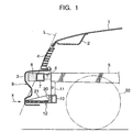
- FIG. 1 shows the structure of the front part of the vehicle body which includes a hood 1 covering the top of an engine compartment.
- the hood 1 is furnished with a hood reinforcement 2 as illustrated, and a radiator grille 4 is provided between a front lower part of the hood 1 and an upper part of a bumper face 3 which is made of resin.
- the vehicle structure includes left and right front side frame members 5 constituting part of a body frame which extends in a longitudinal direction of the vehicle, and a bumper reinforcement 7 is attached to forward ends of the front side frame members 5 via bumper brackets 6 as shown in FIGS. 1 and 2.
- the bumper reinforcement 7 is a lateral supporting member extending in a lateral direction of the front part of the vehicle body.
- An energy absorber 8 is attached to the front of the bumper reinforcement 7 at the same height.
- the energy absorber 8 is an element extending almost all the way across the width of the vehicle body along the bumper face 3 on its inner (or rear) surface.
- the installation height of the energy absorber 8 is so determined that it corresponds to the height of the knees of a pedestrian.
- the bumper face 3, the bumper brackets 6, the bumper reinforcement 7 and the energy absorber 8 together constitute a front bumper 9 which is situated at a lower front position of the hood 1.
- a front cross member 10 (so-called No. 1 cross member) extending widthwise which serves as a structural member of the vehicle body at a bottom front portion of the front side frame members 5, and a bracket 11 such as a radiator shroud member, for instance, is connected to the front cross member 10.
- a front surface of the front cross member 10 supports a rear end of a projecting part 12 as illustrated.
- the projecting part 12 protrudes generally horizontally frontward from the front cross member 10 at a lower part of the front bumper 9.
- a forward end of the projecting part 12 juts out frontward beyond the bumper reinforcement 7 and is located almost at the same longitudinal position as or at a more frontward position than the energy absorber 8.
- the forward end of the projecting part 12 protrudes more frontward than the energy absorber 8.
- the height of the projecting part 12 is determined such that it would come into contact with the shanks (the part between the knee and ankle) of the pedestrian in the event of a collision.
- the height of the projecting part 12 is set to be less than 400mm from a ground, more preferably, in a range of 90mm to 300mm.
- the longitudinal position of the energy absorber 8 is so determined that it would be located ahead of a line L connecting a forward end of the hood 1 and that of the projecting part 12.
- the projecting part 12 is arranged such that it spans all along a lower part of the bumper face 3 in the direction of the vehicle width.
- the projecting part 12 is made of synthetic resin like polypropylene (PP) or polyethylene (PE), for example, into a shape shown in FIG. 3.
- the projecting part 12 is formed of left, right, front and rear frame elements 13-16 which together form a rectangular frame, ribs 17 spanning in the direction of the vehicle width between the left and right frame elements 13, 14 and arranged at specific intervals in the vehicle's longitudinal direction, ribs 18, 19 spanning in oblique directions inside the rectangular frame (frame elements 13-16), a support 20 protruding upward from an upper part of the rear frame element 16, and reinforcement plates 21 which connect the support 20 to the front frame element 15.
- These elements of the projecting part 12 are molded into a single resin structure (honeycomb structure) which has a generally fanlike shape as a whole in plan view.
- This resin structure is constructed such that it would provide desired load characteristics by properly selecting the thickness of the frame elements 13-16 and the spacings and directions of the ribs 17-19.
- the aforementioned reinforcement plates 21 may be eliminated from this structure.
- the projecting part 12 thus constructed is mounted such that it would receive an input load exerted from the front of the vehicle in the direction of an arrow x shown in FIG. 1 with the support 20 at the rear of the projecting part 12 attached to the front surface of the front cross member 10 as shown in FIGS. 1 and 2.
- the load characteristics of the projecting part 12 and the energy absorber 8 are set as shown in FIGS. 4 and 5, respectively.
- FIG. 4 is a graphical representation of the load characteristics "a" of the projecting part 12, in which the horizontal axis represents the amount of deformation (or collapse) while the vertical axis represents the load (dynamic collapsing load).
- the load characteristics "a" of the projecting part 12 are determined such that the input load (expressed in newtons) first increases rapidly from the zero point to a specific load level c in proportion to the amount of deformation and, then, after the projecting part 12 has begun to plastically deform when the input load has reached the load level c, the amount of deformation increases under approximately a constant load.
- FIG. 5 is a graphical representation of the load characteristics "b" of the energy absorber 8, in which the horizontal axis represents the amount of deformation (or collapse) while the vertical axis represents the load (dynamic collapsing load).
- the load characteristics "b" of the energy absorber 8 are determined such that the load (expressed in newtons) increases in proportion to the amount of deformation.
- the rigidity of the projecting part 12 is set to a value larger than that of the energy absorber 8, so that the amount of energy absorbed by the projecting part 12 is larger than the amount of energy absorbed by the energy absorber 8 when they deform by the same amount.
- This embodiment employs energy absorber foam material like styrofoam for the energy absorber 8.
- the energy absorber 8 made of the energy absorber foam material may have either a solid or hollow internal structure, or a structure having a plurality of ribs. Whichever structure is used, the energy absorber 8 is so constructed that it would provide the load characteristics "b" shown in FIG. 5.
- the numeral 22 in FIG. 1 designates a front wheel.
- the aforementioned bumper face 3 is attached by its multiple portions to parts of the vehicle body, including front members of the vehicle like the radiator grille 4, front fenders and the front cross member 10, for instance.
- the pedestrian in the event of a collision between the vehicle and a pedestrian, the pedestrian is swept by parts of his or her legs lower than the knees by the projecting part 12 and thrown over toward the vehicle.
- the pedestrian drops onto the top of the hood 1 so that the pedestrian is protected.
- the energy absorber 8 is provided at the front of the lateral supporting member formed of the bumper reinforcement 7 and the projecting part 12 is provided in such a way that its forward end protrudes more frontward than the lateral supporting member at the lower part of the front bumper 9 as seen above.
- the pedestrian is swept by the parts of his or her legs lower than the knees by the projecting part 12 upon collision, the impact energy exerted on the parts of the legs of the pedestrian thrown over toward the vehicle is absorbed by the energy absorber 8 and the pedestrian drops onto the top of the hood 1, whereby the pedestrian can be protected from secondary damage.
- the foregoing embodiment has such an advantageous effect that the structure of the front of the vehicle can be simplified and the occurrence of malfunction can be prevented as compared to the earlier-mentioned conventional structure in which the air bag accommodated in the front bumper is caused to inflate based on sensor outputs.
- the forward end of the projecting part 12 is located at a more frontward position than a forward end of the energy absorber 8, there is such an advantageous effect that the pedestrian is swept by the parts of his or her legs lower than the knees by the projecting part 12 in a reliable fashion in the event of a collision between the vehicle and the pedestrian.
- the structure of the front of the vehicle of this embodiment has such an advantageous effect that it can protect the legs of the pedestrian from the impact.
- the rigidity of the projecting part 12 is set to a value larger than that of the energy absorber 8 as stated above, there is such an advantageous effect that the projecting part 12 can sweep the legs of the pedestrian by the lower parts than the knees in a reliable fashion.
- the projecting part 12 is made of synthetic resin as stated above, there are produced such advantageous effects that the moldability of the projecting part 12 and ease of its assembly to the vehicle body as well as its flexibility to match the vehicle design are improved.
- the energy absorber 8 is formed as a resin structure made of energy absorber foam material like styrofoam as in the above-described embodiment, or of a different type of energy-absorbing member or damping device, there are produced such advantageous effects that it can positively absorb the impact energy before the pedestrian comes into contact with the hood 1, reduce the speed of the pedestrian as he or she is thrown over, and allow the pedestrian to drop onto the top of the hood 1 in a more reliable fashion.
- the projecting part 12 is attached to the front cross member 10 which is a structural member of the vehicle body at its front, the projecting part 12 can effectively receive the frontal impact load (in the direction of the arrow x shown in FIG. 1) in the event of a collision between the vehicle and a pedestrian and sweep the pedestrian by his or her legs in a reliable fashion. It is also possible to give the projecting part 12 sufficient strength to bear the impact load.
- the projecting part 12 is designed to have such strength that it would not cause damage to the legs of the pedestrian in the event of a collision, a resulting advantageous effect is that the safety of the legs is achieved more positively with the projecting part 12 when it sweeps the pedestrian.
- the projecting part 12 when the projecting part 12 is formed into a honeycomb resin structure as described in the foregoing embodiment, the same leg-sweeping and energy-absorbing effects are obtained no matter which part of front bumper 9 along its length (along the width of the vehicle) hits the pedestrian. Also, when the projecting part 12 is formed of resin material, it would flex when subjected to an upward input load from underneath. This is advantageous with respect to approach angle.
- the load level c of FIG. 4 is set to a value which will not cause damage to the legs of the pedestrian, such as 7000 N (newtons).
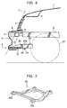
- FIGS. 6 and 7 show the structure of a front part of a vehicle body according to a second embodiment of the invention.
- the projecting part 12 is supported by its rear part by the front cross member 10 in the foregoing embodiment, there is provided a rectangular frame (reinforcing member) 23 which is secured at its both sides below the front side frame members 5 and, with a mounting plate 25 attached to front corners 23a of the rectangular frame 23 by set bolts 24, the rear part of the projecting part 12 is supported by the mounting plate 25 in the embodiment of FIGS. 6 and 7.
- the projecting part 12 may be made of such synthetic resin as polypropylene (PP), polyethylene (PE) or nylon resin.
- FIGS. 6 and 7 The structure of the second embodiment shown in FIGS. 6 and 7 provides substantially the same functional features and advantages as the first embodiment.
- FIGS. 8 and 9 show the structure of a front part of a vehicle body according to a third embodiment of the invention.
- the projecting part 12 is a resin member in the foregoing embodiments
- a projecting part 28 of this embodiment is formed of a backing bar 26 which is a round metal bar like an iron pipe extending along a lower part of the bumper face 3 and a pair of supporting arms 27 connecting the backing bar 26 to the front cross member 10 which is a structural member of the vehicle body.
- Each of the supporting arms 27 is made by forming a piece of sheet metal into a gatelike cross-sectional shape having a top plate portion and left and right side plate portions. The thickness and cross-sectional area of the sheet metal are set to proper values to obtain the load characteristics "a" as depicted in FIG. 4.
- each supporting arm 27 is bent to form a pair of connecting flanges 27a.
- Each supporting arm 27 is fixed to the front surface of the front cross member 10 as these connecting flanges 27a are connected thereto.
- the structure of this embodiment is otherwise the same as the foregoing embodiments.
- the supporting arms 27 may be structural resin members and the backing bar 26 may be made of a round resin bar.
- the projecting part 28 is formed of the backing bar 26 extending along the lower part of the bumper face 3 and the supporting arms 27 which are support members holding the backing bar 26 at the front of the vehicle body.
- This construction is advantageous in that the projecting part 28 having the desired strength and modulus of elasticity can be easily produced.
- FIGS. 10 and 11 show the structure of a front part of a vehicle body according to a fourth embodiment of the invention.
- the energy absorber 8 is made of energy absorber foam material like styrofoam in the foregoing embodiments
- an energy absorber 29 is a structural resin member which is one-piece molded with the bumper face 3 in the embodiment of FIGS. 10 and 11.
- a plurality of horizontal ribs 30 extending widthwise at specific vertical intervals and a plurality of vertical ribs 31 arranged at specific intervals widthwise are formed on the rear surface of the bumper face 3.
- These ribs 30, 31 which are located at the height of the knees of the pedestrian together form a structural resin member 32 which constitutes the energy absorber 29.
- This energy absorber 29 is designed such that its mounting height is approximately equal to that of the bumper reinforcement 7. In addition, the energy absorber 29 is so positioned that it is located ahead of the line L connecting the forward end of the hood 1 and that of the projecting part 12.
- the thickness, spacings and directions of the ribs 30, 31 are properly determined so that the energy absorber 29 provides the load characteristics "b" as depicted in FIG. 5.
- the structure of this embodiment is otherwise the same as the foregoing embodiments.
- the energy absorber 29 can be formed as an integral part of the bumper face 3 and, therefore, this embodiment is advantageous in that it enables reductions in man-hours required for assembly and the number of components.
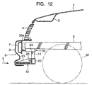
- FIG. 12 shows the structure of a front part of a vehicle body according to a fifth embodiment of the invention. This embodiment is characterized in that an energy absorber 34 is formed of oil dampers 33.
- the oil dampers 33 are attached to the bottom or other peripheral portions of the front side frame members 5 and the bumper reinforcement 7 is connected to forward ends of piston rods 33a of the oil dampers 33 such that the bumper reinforcement 7 can retracts rearward.
- These oil dampers 33 provides the load characteristics "b" as depicted in FIG. 5.
- a frontal impact load (represented by arrow x) will act on the projecting part 12 via the resin bumper face 3 in the event of a collision between the vehicle and a pedestrian.
- This frontal input load is usually smaller than the load level c shown in FIG. 4 and is received by the projecting part 12 whose rear part is sustained by the front cross member 10.
- the pedestrian in the event of a collision between the vehicle and a pedestrian, the pedestrian is swept by parts of his or her legs lower than the knees by the projecting part 12 and impact energy exerted on the legs of the pedestrian thrown over toward the vehicle is absorbed as the bumper reinforcement 7 supported by the oil dampers 33 retracts rearward.
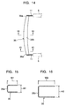
- FIGS. 13-16 show the structure of a front part of a vehicle body according to a sixth embodiment of the invention.
- a projecting part 35 is fixed along a lower part of the rear surface of the bumper face 3.
- This projecting part 35 is installed by its both lateral ends 35a by brackets 11 which serve as downward-extending support members in such a way that the projecting part 35 is installed ahead of and below the front side frame members 5.
- the projecting part 35 has a generally, channel-like cross section whose open side is directed rearward all along its length.
- the projecting part 35 is constructed such that its mechanical strength in the vehicle's longitudinal direction gradually increases from the lateral ends 35a of the projecting part 35 toward its middle part 35b.
- the width W1 and height H1 of the projecting part 35 at its lateral ends 35a shown in FIG. 15 are made smaller than the width W2 and height H2 of the middle part 35b of the projecting part 35 shown in FIG. 16, respectively, so that the strength of the projecting part 35 in the vehicle's longitudinal direction becomes smaller at its lateral ends 35a than at the middle part 35b.
- the structure of this embodiment in which the strength of the projecting part 35 in the vehicle's longitudinal direction gradually increases from its lateral ends 35a toward its middle part 35b provides such advantageous effects that it could prevent the leg-sweeping effect from being deteriorated due to great deflection of the middle part 35b of the projecting part 35 as it hits against the legs of a pedestrian and the distribution of longitudinal load received by the projecting part 35 can be made approximately uniform.
- the projecting part 35 is formed of an elongate member having a generally channel-like cross section opening rearward, there is produced such an advantageous effect that the amount of energy absorbed by the projecting part 35 can be set to a desired value by properly adjusting the degree of its opening.
- the earlier-mentioned lateral supporting member is formed of the a bumper reinforcement 7 and the projecting part 35 is installed ahead of and below the front side frame members 5 by means of the brackets 11, it is possible to give sufficient strength to the projecting part 35 with a simple construction.
- FIGS. 17-20 show the structure of a front part of a vehicle body according to a seventh embodiment of the invention.
- a projecting part 36 is made of an elongate member having a U-shaped cross section whose open side is directed rearward and the strength of the projecting part 36 in the vehicle's longitudinal direction gradually increases from its lateral ends 36a toward its middle part 36b.
- the height H3 of the projecting part 36 at its lateral ends 36a shown in FIG. 19 is made smaller than the height H4 of the middle part 36b of the projecting part 36 shown in FIG. 20, so that the strength of the projecting part 36 in the vehicle's longitudinal direction becomes smaller at its lateral ends 36a than at the middle part 36b.
- the width W4 of the projecting part 36 at its lateral ends 36a is made equal to the width W4 at its middle part 36b.
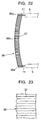
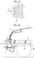
- FIGS. 21 and 22 show variations of the sixth and seventh embodiments shown in FIGS. 13-16 and 17-20, respectively.
- the projecting parts 35 and 36 have corrugated surfaces 37 having alternating furrows and ridges formed parallel to the longitudinal direction of the vehicle body.
- the furrows and ridges of the corrugated surface 37 which have been spaced at regular intervals before impact as shown in FIG. 23 collapse upon impact as shown in FIG. 24, in which the furrows and ridges come close to each other at the front of the corrugated surface 37 and are separated from each other at the rear of the projecting part 35 (36) due to a frontal impact load (represented by arrow x). Since this deformation of the corrugated surface 37 sequentially propagates across the furrows and ridges in the direction of the vehicle width in the event of a collision, the projecting part 35 (36) can effectively absorb impact energy caused by the collision.
- the provision of the corrugated surfaces 37 on the projecting parts 35, 36 adds rigidity to the projecting parts 35, 36. This reinforcing effect is advantageous in that it helps to achieve sufficient strength even when the projecting parts 35, 36 are made thinner.
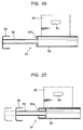
- FIGS. 25-27 show the structure of a front part of a vehicle body according to an eighth embodiment of the invention.
- a projecting part 35 in such a way that a forward end of the projecting part 35 juts out frontward beyond the bumper reinforcement 7 at a lower part of the front bumper 9, and tie-down hook plates 80 ahead of and below the left and right front side frame members 5, wherein left and right ends of the projecting part 35 are sustained by the respective tie-down hook plates 80 via left and right energy-absorbing pipe assemblies 81.
- the energy-absorbing pipe assemblies 81 absorb impact energy in the event of a collision as they retract when the projecting part 35 is forced rearward.
- Each energy-absorbing pipe assembly 81 is formed of a front pipe section (first tubular portion) 82 having a smaller diameter which is joined directly to the rear of the projecting part 35 and a rear pipe section (second tubular portion) 83 having a larger diameter whose forward end is fixed to a rear peripheral part of the front pipe section 82 by welding, for instance.
- a peripheral part of the rear pipe section 83 is then joined to the corresponding tie-down hook plate 80.
- the front pipe section 82 has a curved funnellike bend 82a at its rear end. This bend 82a is formed by radially folding back the rear end of the front pipe section 82 and firmly connected to the forward end of the rear pipe section 83.
- designated by the numeral 84 is an opening for hooking and designated by the numeral 23 is a rectangular frame.
- each energy-absorbing pipe assembly 81 deforms and is forced into the rear pipe section 83 as shown in FIG. 27, whereby the impact energy is absorbed at a constant input load.
- this embodiment provides such an advantageous effect that it is possible to obtain sufficient rigidity to support the projecting part 35.
- the projecting part 35 is backed by the energy-absorbing pipe assemblies 81 whose retracting motion serves to absorb the impact energy, there are such advantageous effects that the impact energy can be effectively absorbed between the projecting part 35 and the tie-down hook plates 80 in the event of a collision and the energy-absorbing pipe assemblies 81 can be securely supported by the tie-down hook plates 80.
- each energy-absorbing pipe assembly 81 provided at the rear of the projecting part 35 is forced rearward along and into the rear pipe section 83 (second tubular portion) while absorbing the impact energy in the event of a collision between the vehicle and a pedestrian.
- the front pipe section 82 retracts while maintaining prescribed conditions of joint between the rear peripheral part of the front pipe section 82 and the forward end of the rear pipe section 83.
- the structure of this embodiment provides such an advantageous effect that it can absorb the impact energy at a constant input load with the stroke (rearward movement) of the projecting part 35.
- FIG. 28 shows another example of energy-absorbing pipe assemblies 81 provided between the projecting part 35 and the tie-down hook plates 80, in which an attachment 85 is fitted to a forward end of the front pipe section 82 of each energy-absorbing pipe assembly 81.
- the attachment 85 has a load transmitting part 85a whose outside diameter is equal to that of the front pipe section 82 and a mounting part 85b which extends frontward from the load transmitting part 85a and whose outside diameter is smaller than that of the front pipe section 82.
- the attachment 85 is fitted by its mounting part 85b to the bottom of a channel-like opening of the projecting part 35 on its rear side.
- FIGS. 29 and 30 show the structure of a front part of a vehicle body according to a ninth embodiment of the invention.
- the projecting part 86 is installed in approximately a horizontal position ahead of and below the front side frame members 5 by means of tie-down hook plates 80 such that a forward end of the projecting part 86 juts out frontward beyond the bumper reinforcement 7 at a lower part of the front bumper 9.
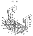
- the projecting part 86 is made of synthetic resin like polypropylene (PP) or polyethylene (PE) into the shape shown in FIG. 30.
- PP polypropylene
- PE polyethylene
- the projecting part 86 is formed of left, right, front and rear frame elements 87-90 which together form a rectangular frame, ribs 91 spanning in the direction of the vehicle width between the left and right frame elements 87, 88 and arranged at specific intervals in the vehicle's longitudinal direction, a rib 92 extending in the longitudinal direction at the middle of the width of the projecting part 86, ribs 93, 94 spanning in oblique directions inside the rectangular frame (frame elements 87-90), and fixing tabs 95 projecting upward from upper rear terminal parts of the left and right frame elements 87, 88.
- These elements of the projecting part 86 are molded into a single resin structure (honeycomb structure) which has a generally fanlike shape as a whole in plan view.
- This resin structure is constructed such that it would provide desired load characteristics by properly selecting the thickness of the frame elements 87-90 and the spacings and directions of the ribs 91-94.
- the resin projecting part 86 thus constructed is installed by securing the fixing tabs 95 to the tie-down hook plates 80 with fixing parts 96 such as bolts and nuts.
- this projecting part 86 has the central longitudinal rib 92 and is formed into the generally fanlike shape in plan view, mechanical strength of the projecting part 86 in the vehicle's longitudinal direction gradually increases from its left and right ends to its middle part.
- the pedestrian in the event of a collision between the vehicle and a pedestrian, the pedestrian is swept by parts of his or her legs lower than the knees by the projecting part 86. After impact energy exerted on the parts of the legs of the pedestrian who is thrown over toward the vehicle has been absorbed by the energy absorber 8, the pedestrian drops onto the top of the hood 1 so that the pedestrian is protected.
- the structure of this embodiment provides such an advantageous effect that the projecting part 86 receives approximately the same level of frontal load in the event of a collision no matter which part of projecting part 86 along its length (along the width of the vehicle) hits the pedestrian.
- another advantage of using this structure is that the projecting part 86 can deform at any portion over the entire length of the projecting part 86 at substantially the same amount in the event of a collision.
- each fixing tab 95 for fitting the fixing parts 96 when fixing the projecting part 86 to the tie-down hook plates 80.
- the front fixing hole may be formed into a vertically extending slot so that the projecting part 86 can be moved upward if it interferes (or collides) with the road surface or with an obstacle on the road surface. This would help prevent breakage and other damages to the projecting part 86 and confer an advantage with respect to approach angle.
- FIG. 31 shows the structure of a front part of a vehicle body according to a tenth embodiment of the invention.
- a bumper face 3 made of resin and an energy absorber 40A which is assembled with the bumper face 3 on its rear surface to together form a single structure.
- This energy absorber 40A is located at a position corresponding to the height of the knees of a pedestrian ahead of the bumper reinforcement 7 (lateral supporting member).
- a lower leg supporting part 41A extending in the direction of the vehicle width is provided integrally with the bumper face 3 at a lower part of its rear surface, and a rear portion of the lower leg supporting part 41A is supported by the front cross member 10 which is a specific example of a structural member of the vehicle body.
- the energy absorber 40A and the lower leg supporting part 41A are combined with the bumper face 3 all the way along the length of the front bumper 9 (i.e., across the vehicle width).
- a rectangular frame shown in FIG. 7 may be used as a structural member of the vehicle body instead of the front cross member 10. Also, in a vehicle which is not provided with the front cross member 10, stays (not shown) extended downward from the front side frame members 5 or from the bumper reinforcement 7 may be used as structural members of the vehicle body.
- the gap g is zeroed and a forward end of the lower leg supporting part 41A juts out more frontward than that of the energy absorber 40A. More particularly, although the forward end of the lower leg supporting part 41A is located more rearward than that of the energy absorber 40A under normal conditions shown in FIG. 31, the forward end of the lower leg supporting part 41A juts out more frontward than that of the energy absorber 40A when the bumper face 3 is displaced rearward and the gap g is zeroed in the event of a collision between the vehicle and the pedestrian.
- the energy absorber 40A is made of the same synthetic resin material as the bumper face 3, such as polypropylene (PP), and is constructed such that it extends in the direction of the vehicle width along an upper part of the rear surface of the bumper face 3 ahead of the bumper reinforcement 7.
- PP polypropylene
- the energy absorber 40A is formed of a main structural part 42 extending in the direction of the vehicle width in an upright position, a plurality of horizontal front ribs 43 and vertical front ribs 44 extending frontward from a front surface of the main structural part 42, and a plurality of horizontal rear ribs 45 and vertical rear ribs 46 extending rearward from a rear surface of the main structural part 42.
- the rigidity of the energy absorber 40A at root portions of the horizontal front ribs 43 is made smaller than that of the energy absorber 40A at root portions of the horizontal rear ribs 45.
- the thickness of the horizontal front ribs 43 is made smaller than that of the horizontal rear ribs 45 and the spacing between at least the horizontal front ribs 43 is made larger than that between the horizontal rear ribs 45.
- the spacing between the vertical front ribs 44 may also be made larger than that between the vertical rear ribs 46.
- the energy absorber 40A thus constructed is integrally joined to a specific part of the rear surface of the bumper face 3 by heat bonding, for instance.
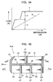
- the energy absorber 40A provides generally steplike load characteristics "f" (two-step energy-absorbing characteristics) as illustrated in FIG. 34. As a whole, the amount of energy absorbed by the energy absorber 40A is increased compared to the foregoing embodiments that provide the load characteristics "b".
- the lower leg supporting part 41A is made of the same synthetic resin material as the bumper face 3, such as polypropylene (PP), and is constructed such that it extends in the direction of the vehicle width along a lower part of the rear surface of the bumper face 3.
- PP polypropylene
- the lower leg supporting part 41A has a generally upright front strip 47, an upright rear strip 48, a horizontal main stiffening plate 49 which extends in the vehicle's longitudinal direction between the front strip 47 and the rear strip 48. These elements together constitute a main structural part 50 having a generally H-shaped cross section. Further, a plurality of upper ribs 51 extending in the longitudinal direction and an upper rib 52 extending in the direction of the vehicle width are formed on a top surface of the main stiffening plate 49 while a plurality of lower ribs 53 extending in the longitudinal direction and a lower rib 54 extending in the direction of the vehicle width are on a bottom surface of the main stiffening plate 49.
- the spacings between the front strip 47, the upper rib 52 and the rear strip 48 in the vehicle's longitudinal direction and the spacings between the upper ribs 51 in the vehicle's lateral direction are made rather large on the top side of the main stiffening plate 49, whereas the spacings between the front strip 47, lower rib 54 and the rear strip 48 in the vehicle's longitudinal direction and the spacings between the lower ribs 53 in the vehicle's lateral direction are made smaller on the bottom side of the main stiffening plate 49.
- clearance C1 (or cutout) as a marginal space between a rear end of each upper rib 51 on the front side and a front surface of the upper rib 52.
- clearance C2 (or cutout) as a marginal space between a rear end of each lower rib 53 and a front surface of the rear strip 48.
- the lower leg supporting part 41A thus constructed is integrally joined to a specific part of the rear surface of the bumper face 3 by heat bonding, for instance.
- FIG. 38 is a graphical representation of the load characteristics "a" of the lower leg supporting part 41A, in which the horizontal axis represents the amount of deformation (or collapse) while the vertical axis represents the load (dynamic collapsing load).
- the load characteristics "a" of the lower leg supporting part 41A are determined such that the input load (expressed in newtons) first increases rapidly from the zero point to a specific load level c in proportion to the amount of deformation and, then, after the lower leg supporting part 41A has begun to plastically deform when the input load has reached the load level c, the amount of deformation increases under approximately a constant load.
- the load level c of the aforementioned load characteristics "a" can be easily adjusted as to a desired level as shown by alternate long and two short dashed lines in FIG. 38 by changing the thickness and spacings of the individual ribs 51-54.
- the rigidity of the lower leg supporting part 41A depicted in FIGS. 35-37 is made smaller than that of the energy absorber 40A.
- "FR" designates the forward direction of the vehicle.
- the lower leg supporting part 41A sweeps the pedestrian by parts of his or her legs lower than the knees and the laterally extending energy absorber 40A absorbs impact energy exerted on the parts of the legs of the pedestrian who is thrown over toward the vehicle in two discrete steps as shown in FIG. 34. Then, the pedestrian drops onto the top of the hood 1 so that the pedestrian is protected.
- the front bumper 9 associated with the bumper face 3, the bumper reinforcement 7 (lateral supporting member) located behind the bumper face 3, and the lower leg supporting part 41A extending in the direction of the vehicle width at a lower part of the front bumper 9 with the rear portion of the lower leg supporting part 41A supported by the front cross member 10 (which is the structural member of the vehicle body) as seen above. Since the forward end of the lower leg supporting part 41A juts out relatively frontward compared to the bumper reinforcement 7 (lateral supporting member) when the bumper face 3 is displaced rearward, the structure of this embodiment provides the following advantageous effects.
- the forward end of the lower leg supporting part 41A juts out relatively frontward compared to the bumper reinforcement 7 (lateral supporting member) and the lower leg supporting part 41A whose rear portion is supported by the front cross member 10 (structural member of the vehicle body) receives a frontal impact load exerted in the direction of the arrow x in FIG. 31.
- the pedestrian is swept by parts of his or her legs lower than the knees by the lower leg supporting part 41A upon collision so that the pedestrian thrown over toward the vehicle is caused to drop onto the top of the hood 1 in a reliable fashion. There is produced such an advantageous effect that the pedestrian can be protected from secondary damage.
- the present embodiment is also advantageous in that it is possible to provide increased safety of the legs of the pedestrian by properly selecting the strength (or load characteristics) of the lower leg supporting part 41A, simplify the structure of the front of the vehicle and prevent the occurrence of malfunction. Furthermore, there are no limitations in the design of the front bumper 9 so that its assembly can be simplified.
- the aforementioned lateral supporting member is formed of the bumper reinforcement 7, it is possible to effectively use the already existing member, eliminating the need to additionally provide a member extending in the direction of the vehicle width.
- the aforementioned energy absorber 40A is formed of the main structural part 42 and the ribs 43-46 and joined to the bumper face 3 to together form a single structure, there is such an advantageous effect that it is possible to increase the amount of absorbed energy and adjust the amount of absorbed energy more easily by determining the thickness and spacings of the individual ribs 43-46 as appropriate.
- the lower leg supporting part 41A Since there is provided the gap g of the specific distance between the energy-absorbing ribs 45, 46 of the energy absorber 40A and the bumper reinforcement 7, the lower leg supporting part 41A is allowed to relatively juts out when the bumper face 3 is displaced rearward in the event of a collision between the vehicle and a pedestrian. As a result, there is produced such an advantageous effect that the lower leg supporting part 41A can sweep the pedestrian by his or her lower legs in a reliable fashion.
- the aforementioned lower leg supporting part 41A has the ribs 51-54 and the spacings between the upper ribs 51, 52 are made relatively large while the spacings between the lower ribs 53, 54 are made smaller, it allows deflection of the lower leg supporting part 41A and provides an increased approach angle when a load is exerted from the road surface. It is to be pointed out that if the spacings between both the upper ribs 51, 52 and the lower ribs 53, 54 are small, deflection of the lower leg supporting part 41A would be hindered.
- the energy absorber 40A is provided with the front ribs 43, 44 and the rear ribs 45, 46, and the modulus of elasticity of the front ribs 43, 44 is set to a small value while that of the rear ribs 45, 46 is set to a large value, there is produced such an advantageous effect that the impact energy exerted on the lower legs of the pedestrian is initially alleviated and a sufficient amount of energy is later absorbed.
- steplike energy-absorbing characteristics "f" (FIG. 34) are obtained with the structure of this embodiment, the amount of the absorbed energy is increased as a whole. Also, the provision of the ribs 43-46, 51-54 serves to facilitate the adjustment of the amount of the absorbed energy.
- the thickness of the front ribs 43, 44 of the energy absorber 40A is made relatively small and that of the rear ribs 45, 46 is made larger, there is produced such an advantageous effect that the energy absorber 40A can initially alleviate the impact energy upon collision and eventually absorb a sufficient amount of energy.
- the spacings between the front ribs 43, 44 of the energy absorber 40A are made relatively large and the spacings between the rear ribs 45, 46 are made smaller, there is produced such an advantageous effect that the energy absorber 40A can initially alleviate the impact energy upon collision and eventually absorb a sufficient amount of energy.
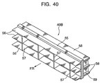
- FIGS. 39 and 40 show an energy absorber 40B (energy-absorbing ribs) in one variation of the tenth embodiment, in which the energy absorber 40B is integrally joined to the rear surface of the bumper face 3 by heat bonding, for instance, such that the energy absorber 40B is positioned face to face with the bumper reinforcement 7.
- This energy absorber 40B is made of the same synthetic resin material as the bumper face 3, such as polypropylene (PP), and is constructed such that it extends in the direction of the vehicle width along the bumper face 3 ahead of the bumper reinforcement 7.
- PP polypropylene
- the energy absorber 40B is formed of a main structural part 55 extending in the direction of the vehicle width in an upright position, a plurality of horizontal front ribs 56 and vertical front ribs 57 extending frontward from a front surface of the main structural part 55, and a plurality of horizontal rear ribs 58 and vertical rear ribs 59 extending rearward from a rear surface of the main structural part 55.
- the horizontal front ribs 56 extending frontward are tapered such that they become narrower from their rear root portions toward their front ends.
- the energy absorber 40B is so constructed that the amount of energy absorbed by the horizontal front ribs 56 are relatively small as compared to the amount of energy absorbed by the horizontal rear ribs 58.
- the thickness (cross-sectional area) of the horizontal front ribs 56 is made smaller than that of the horizontal rear ribs 58 and the spacing between the vertical front ribs 57 is made larger than that between the vertical rear ribs 59.
- the energy absorber 40B thus constructed is integrally joined to a specific part of the rear surface of the bumper face 3 by heat bonding, for instance.
- the energy absorber 40B provides generally steplike load characteristics "h" (two-step energy-absorbing characteristics) as illustrated in FIG. 41. As a whole, the amount of energy absorbed by the energy absorber 40B is increased compared to the foregoing embodiments that provide the load characteristics "b".
- FIG. 41 is a graphical representation of the load characteristics "h" of the energy absorber 40B, in which the horizontal axis represents the amount of deformation (or collapse) while the vertical axis represents the load (dynamic collapsing load).
- the energy absorber 40B of FIGS. 39-41 provides substantially the same functional features and advantages as the foregoing embodiments.
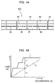
- FIGS. 42-44 show an energy absorber 40C (energy-absorbing ribs) in another variation of the tenth embodiment, in which the energy absorber 40C is integrally joined to the rear surface of the bumper face 3 by heat bonding, for instance, such that the energy absorber 40C is positioned face to face with the bumper reinforcement 7.
- This energy absorber 40C is made of the same synthetic resin material as the bumper face 3, such as polypropylene (PP), and is constructed such that it extends in the direction of the vehicle width along the bumper face 3 ahead of the bumper reinforcement 7.
- PP polypropylene
- the energy absorber 40C is formed of a main structural part 60 extending in the direction of the vehicle width in an upright position, a plurality of horizontal ribs 61-64 extending frontward in a steplike fashion from a front surface of the main structural part 60, and a plurality of vertical ribs 65-67 which vertically connect the multiple horizontal ribs 61-64.
- the ribs 61, 62 and 65 work as front ribs
- the ribs 63 and 66 work as middle ribs
- the ribs 64 and 67 work as rear ribs.
- the energy absorber 40C energy-absorbing ribs
- the energy absorber 40C provides generally steplike load characteristics "j" (three-step energy-absorbing characteristics) as illustrated in FIG. 45.
- the amount of energy absorbed by the energy absorber 40C is increased compared to the foregoing embodiments that provide the load characteristics "b".
- FIG. 45 shows a graphical representation of the load characteristics "j" of the energy absorber 40C, in which the horizontal axis represents the amount of deformation (or collapse) while the vertical axis represents the load (dynamic collapsing load).
- the energy absorber 40C thus constructed is integrally joined to a specific part of the rear surface of the bumper face 3 by heat bonding, for instance.
- the energy absorber 40C of FIGS. 42-45 provides substantially the same functional features and advantages as the foregoing embodiments.
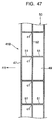
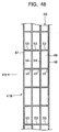
- FIGS. 46-48 show a lower leg supporting part 41B whose rear portion is supported by the front cross member 10 which is a structural member of the vehicle body in still another variation of the tenth embodiment, in which elements identical or equivalent to those depicted in FIGS. 35-37 are designated by the same reference numerals.
- the lower leg supporting part 41B of this variation of the tenth embodiment also has a plurality of ribs 51-54 like the lower leg supporting part 41A of FIGS. 35-37, the thickness of the upper rib 52 is made smaller and that of the lower rib 54 is made larger.
- the lower leg supporting part 41B of this variation shown in FIGS. 46-48 is formed of the multiple ribs 51-54, and the thickness of the upper rib 52 is made smaller and that of the lower rib 54 is made larger, it allows deflection of the lower leg supporting part 41B and provides an increased approach angle when a load is exerted from the road surface.
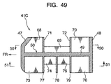
- FIGS. 49-51 show a lower leg supporting part 41C whose rear portion is supported by the front cross member 10 which is a structural member of the vehicle body in yet another variation of the tenth embodiment, in which elements identical or equivalent to those depicted in FIGS. 35-37 are designated by the same reference numerals.
- the lower leg supporting part 41C of FIGS. 49-51 has a main structural part 50 formed of a front strip 47, a rear strip 48 and a horizontal main stiffening plate 49 which together form a generally H-shaped cross section like the lower leg supporting part 41A of FIGS. 35-37.
- a plurality of upper ribs 68-70 formed parallel to the vehicle's longitudinal direction and upper ribs 71, 72 formed parallel to the direction of the vehicle width extend upward from a top surface of the main stiffening plate 49 of the main structural part 50 while a plurality of lower ribs 73-76 formed parallel to the vehicle's longitudinal direction and lower ribs 77-79 formed parallel to the direction of the vehicle width extend downward from a bottom surface of the main stiffening plate 49 of the main structural part 50.
- the spacings between the front strip 47, the upper ribs 71, 72 and the rear strip 48 in the vehicle's longitudinal direction and the spacings between the upper ribs 68-70 in the vehicle's lateral direction are made rather large on the top side of the main stiffening plate 49, whereas the spacings between the front strip 47, the lower ribs 77-79 and the rear strip 48 in the vehicle's longitudinal direction and the spacings between the lower ribs 73-76 in the vehicle's lateral direction are made smaller on the bottom side of the main stiffening plate 49.
- the height of the upper ribs 68, 70 is determined such that they become generally flush with upper ends of the upper ribs 71, 72 and the height of the upper ribs 69 located in the middle of the longitudinal dimension of the lower leg supporting part 41C is made smaller (one-half in this variation of the tenth embodiment) than that of the upper ribs 68, 70.
- the amount of downward projection of the lower ribs 73, 76 is determined such that they become generally flush with lower ends of the lower ribs 77-79 and the amount of downward projection of the lower ribs 74, 75 located in the middle of the longitudinal dimension of the lower leg supporting part 41C is made smaller (one-half in this variation of the tenth embodiment) than that of the lower ribs 73, 76.
- the aforementioned ribs 69, 74, 75 together constitutes a portion which allows deflection of the lower leg supporting part 41C.
- the lower leg supporting part 41C produces substantially the same effects as the lower leg supporting parts 41A and 41B without the provision of the clearances C1, C2 shown in FIGS. 35-37, 46-48.
- the lower leg supporting part 41C of FIGS. 49-51 is so constructed as to enable its own deflection and provide an increased approach angle when a load is exerted from the road surface by decreasing the height of the upper ribs 69 and the amount of projection of the lower ribs 74, 75.
- the lower leg supporting part 41C thus constructed is integrally joined to a specific part of the rear surface of the bumper face 3 by heat bonding, for instance.
- the lower leg supporting part 41C of FIGS. 49-51 provides substantially the same functional features and advantages as the foregoing embodiments.
- the energy absorbers 40A, 40B, 40C and the lower leg supporting parts 41A, 41B, 41C of the foregoing embodiments each employ a rib structure in which two sets of parallel ribs intersect at right angles, these ribs may be arranged such that they intersect at other than right angles.
- a honeycomb structure may be employed instead of the rib structure.
- Another alternative approach would be to construct the rib structure in such a manner that at least part of the ribs are formed at an oblique angle to achieve a uniform distribution of loads.
- a desired combination of an energy absorber and a lower leg supporting part which are assembled integrally with the bumper face 3 may be selected from the energy absorbers 40A, 40B, 40C and the lower leg supporting parts 41A, 41B, 41C of the foregoing embodiments.
- the energy absorber 40A may be combined with the lower leg supporting part 41C, or the energy absorber 40B may be combined with the lower leg supporting part 41A, as appropriate.
- one of the lower leg supporting parts 41A, 41B, 41C may be combined with the earlier-mentioned energy absorber 8.
- one each of the energy absorbers 40A, 40B, 40C and the lower leg supporting parts 41A, 41B, 41C may be integrally joined to the bumper face 3 by adhesive bonding or any of other appropriate methods instead of heat bonding.
- the expression “bumper” corresponds to the front bumper 9 referred to in the foregoing embodiments.
- “lateral supporting member” corresponds to the bumper reinforcement 7
- “support member” corresponds to the supporting arm 27
- “damping device” corresponds to the oil damper 33
- "structural member of the vehicle body” corresponds to the front cross member 10
- the rectangular frame 23 or stays corresponds to the gap g. It is to be noted, however, that the present invention is not limited to the structures of the foregoing embodiments.
- the energy absorbers 40A, 40B, 40C and the lower leg supporting parts 41A, 41B, 41C need not necessarily be made of polypropylene (PP) but may be made of other appropriate resin material.
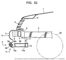
- FIGS. 52 and 53 show the structure of a front part of a vehicle body according to an eleventh embodiment of the invention.
- the structure of this embodiment includes a front cross member 10 extending widthwise which serves as a structural member of the vehicle body, and a bracket 11 such as a radiator support member is connected to the front cross member 10.
- a plurality of hollow impact-receiving members 38 made of metal plates like iron plates are attached to the front of the front cross member 10. Although there are provided three impact-receiving members 38 in this embodiment as shown in FIG. 53, the central impact-receiving member 38 may be eliminated in a varied form of the embodiment.
- the impact-receiving members 38 are designed such that their yield strength is lower than that of the bumper reinforcement 7 and a front surface 38a of each impact-receiving member 38 is recessed rearward in the middle of its height forming a recess.
- This backing bar 39 extends in the direction of the vehicle width and is integrally attached to the bumper face 3.
- a round metal pipe made of iron, for instance, is used as the backing bar 39.
- This round pipe is bent before installation to give it a curved shape (camber) that would properly fit on the bumper face 3 and is embedded in a lower cylindrical bulging portion 3a on the rear surface of the bumper face 3 which is made of resin.
- the aforementioned impact-receiving members 38 are installed behind the backing bar 39 in such a manner that they are positioned face to face with each other with a specified gap Ga between the rearmost part of the backing bar 39 and front surfaces 38a of the impact-receiving members 38.
- the longitudinal positions of the bumper reinforcement 7 and the impact-receiving members 38 are determined such that the backing bar 39 would come in contact with the impact-receiving members 38 ahead of the front surface of the bumper reinforcement 7 in the event of a collision. This arrangement is used to prevent impact which could be caused if the bumper face 3 directly hits against the bumper reinforcement 7 when displaced rearward.
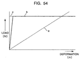
- FIG. 54 is a graphical representation of the load characteristics "a" of the energy absorber 8 and the load characteristics "b” of the impact-receiving members 38.
- the load characteristics "a" of the energy absorber 8 are determined such that input load and the amount of deformation are proportional to each other.
- the load characteristics "b" of the impact-receiving members 38 are determined such that the input load (expressed in newtons) first increases rapidly from the zero point to a specific load level c in proportion to the amount of deformation and, then, after the impact-receiving members 38 have begun to plastically deform when the input load has reached the load level c, the amount of deformation increases under approximately a constant load.
- the modulus of elasticity of the impact-receiving members 38 is set to a value larger than that of the energy absorber 8.
- the impact-receiving members 38 exhibit the load characteristics "b" depicted in FIG. 54 after the aforementioned gap Ga has been zeroed when the backing bar 39 mounted on the bumper face 3 has been displaced rearward and gone into contact with the front surfaces 38a of the impact-receiving members 38 in the event of a collision between the vehicle and a pedestrian. It is preferable that the load level c of the load characteristics "b" of the impact-receiving members 38 be set to a value not exceeding 7000 N (newtons) to prevent damage to the legs of the pedestrian.
- the load is exerted on the resin bumper face 3 in the direction of an arrow x shown in FIG. 52 in the event of a collision between the vehicle and a pedestrian and, as a consequence, the backing bar 39 is displaced rearward together with the bumper face 3 while absorbing impact energy and comes into contact with the front surfaces 38a of the impact-receiving members 38.
- the pedestrian in the event of a collision between the vehicle and a pedestrian, the pedestrian is swept by parts of his or her legs lower than the knees by the backing bar 39 and thrown over toward the vehicle. After the impact energy exerted on the pedestrian when his or her legs come in contact with a portion of the bumper face 3 where the energy absorber 8 is located has been absorbed, the pedestrian is caused to drop onto the top of the hood 1.
- the pedestrian Since the pedestrian is swept by parts of his or her legs lower than the knees by the backing bar 39 and caused to drop onto the top of the hood 1 upon collision as described above, it is possible to protect the pedestrian from secondary damage.
- the structure of this embodiment also provides such an advantageous effect that it is possible to protect the legs of the pedestrian by properly determining the load characteristics "b" of the impact-receiving members 38. Furthermore, since the backing bar 39 is integrally fitted to the bumper face 3, the embodiment provides extra ease of assembly. Also, the structure of this embodiment is simple and the occurrence of malfunction is prevented as it is not necessary to provide sensors and an air bag unlike the earlier-mentioned conventional structure.
- the backing bar 39 is embedded in the resin bumper face 3 in the structure of this embodiment, it is possible to reliably retain the backing bar 39 which is a functional component in the lower part of the bumper face 3 and enhance productivity and ease of assembly.
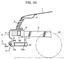
- a backing bar 39 made of a round iron pipe is embedded in the lower part of the bumper face 3 in the structure of the eleventh embodiment, a backing bar 39a made of a round resin pipe may be integrally bonded to a lower part of the rear surface of a bumper face 3 by adhesive bonding or heat bonding as shown in FIG. 55.
- the bumper face 3 and the backing bar 39a may be made of such thermoplastic materials as synthetic resin as polypropylene (PP), acrylonitrile butadiene styrene (ABS) resin or polyethylene (PE).
- this twelfth embodiment in which the backing bar 39a is fixed to the lower part of the bumper face 3 made of resin facilitates molding process compared to the eleventh embodiment in which the backing bar 39 made of metal is embedded in the bumper face 3.
- this embodiment provides such an advantageous effect that the strength of the backing bar 39a can be easily adjusted by changing its diameter, for example.
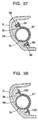
- FIGS. 56 and 57 show the structure of a front part of a vehicle body according to a thirteenth embodiment of the invention, in which a backing bar 39 made of a round metal pipe is integrally fixed to a lower part of the rear surface of a bumper face 3 by a plurality of clamps 97.
- a plurality of ribs 3b on the lower part of the rear surface of the bumper face 3 at specific intervals in the direction of the vehicle width.
- a mounting groove 3c having a semicircular cross section which properly fits on the curved outer surface of the backing bar 39 is formed in each rib 3b and fixing nuts 98 are embedded therein.
- the clamps 97 may be fixed to the bumper face 3 by using tapping screws 100 as shown in FIG. 58.
- backing bar corresponds to the backing bar 39, 39a made of a round metal pipe or round resin bar referred to in the foregoing embodiments.
- structural member of the vehicle body corresponds to the front cross member 10
- impact-receiving member corresponds to the hollow impact-receiving member 38 made of iron plates. It is to be noted, however, that the present invention is not limited to the structures of the foregoing embodiments.
- the front cross member 10 serving as a structural member (reinforcing member) of the vehicle body may be replaced by a specific part of a rectangular frame.
- impact-receiving members 38 of the structure of FIG. 52 are made of metal plates, they may be replaced such members as mechanical damping devices or structural resin members.
- the bumper face 3 and the resin backing bar 39a may be one-piece molded using an injection blow molding machine.
- the backing bar 39 is made of a round metal pipe in the structure of FIG. 52, it may be replaced by a pipe having a varying diameter or by a combination of pipes having a stepped cross section.
- Another alternative construction is to integrally attach the backing bar 39 made of a round metal pipe to a lower part of the rear surface of the bumper face 3 by adhesive bonding.
- a structure of a front part of a vehicle body in which a bumper is provided at a lower front position of a hood at the front of the vehicle comprises a lateral supporting member provided in the front part of the vehicle body and extending in the direction of vehicle width, an energy-absorbing member provided ahead of the lateral supporting member, and a projecting part provided at a lower part of the bumper in such a manner that a forward end of the projecting part juts out more frontward than the lateral supporting member.
- the projecting part first sweeps the pedestrian by parts of his or her legs lower than the knees in the event of a collision between the vehicle and the pedestrian, and after the energy-absorbing member has absorbed the impact energy exerted on the legs of the pedestrian who is thrown over toward the vehicle, the pedestrian is caused to drop onto the top of the hood. Consequently, there is produced such an advantageous effect that the pedestrian can be protected from secondary damage.
- Another advantageous effect is that it is possible to provide increased safety of the legs of the pedestrian by properly selecting the strength of the projecting part, simplify the structure of the front of the vehicle and prevent the occurrence of malfunction.
- the lateral supporting member is formed of a bumper reinforcement. Since the laterally extending bumper reinforcement is used as the lateral supporting member in this structure, it is made possible to effectively use the already existing member.
- the forward end of the projecting part is located at a more frontward or rearward position than a forward end of the energy-absorbing member.
- the energy-absorbing member is located ahead of a line connecting a forward end of the hood and the forward end of the projecting part. This structure is advantageous in that the energy-absorbing member absorbs impact energy exerted on the legs of the pedestrian who is thrown over toward the vehicle even more effectively, making it possible to protect the legs of the pedestrian from the impact energy.
- the rigidity of the projecting part is set to a value larger than that of the energy-absorbing member. This approach is advantageous in that it enables the projecting part to sweep the pedestrian by his or her lower legs in a reliable fashion.
- the projecting part is formed of a resin member.
- This structure is advantageous in that it provides improved moldability of the projecting part, ease of its assembly to the vehicle body, and gives the projecting part more flexibility to match the vehicle design.
- the projecting part includes a backing bar extending along a lower part of a bumper face and a support member which holds the backing bar at the front of the vehicle body.
- the energy-absorbing member is an energy-absorbing metal member, a structural resin member or a mechanical damping device.
- This structure is advantageous in that the energy-absorbing member can positively absorb the impact energy before the pedestrian comes into contact with the hood, reduce the speed of the pedestrian as he or she is thrown over, and allow the pedestrian to drop onto the top of the hood in a more reliable fashion.
- the projecting part is attached to a structural member of the vehicle body provided in its front part.
- This structure is advantageous in that the projecting part can effectively receive a frontal impact load in the event of a collision and sweep the pedestrian by his or her legs in a reliable fashion give the projecting part sufficient strength to bear the impact load.
- the lateral supporting member is attached to forward ends of left and right front side frame members, the projecting part is installed ahead of and below the front side frame members, and the strength of the projecting part in the vehicle's longitudinal direction increases from its left and right ends to its middle part.
- This structure is advantageous in that it prevents the middle of the projecting part from becoming liable to flex an the distribution of longitudinal load received by the projecting part in the event of a collision can be made approximately uniform.
- the lateral supporting member is attached to forward ends of left and right front side frame members, the projecting part is installed ahead of and below the front side frame members, and the projecting part has a U-shaped or channel-like cross section whose open side is directed rearward.
- the projecting part having either the U-shaped or the channel-like cross section can easily be deformable upon receipt of the impact energy at the time of collision, compared to the projecting part having a completely filled in cross section.
- this structure is advantageous in that it can effectively absorb the impact energy in the event of a collision.
- the projecting part has a corrugated surface having alternating furrows and ridges formed parallel to the vehicle's longitudinal direction.
- This structure is advantageous in that the alternating furrows and ridges prevents a rapid decline in yield strength of the projecting part due to its deformation in the vehicle's longitudinal direction when an impact load is exerted on the projecting part in the event of a collision between the vehicle and a pedestrian and, as a consequence, the projecting part can absorb the impact energy at a constant input load as it deforms rearward.
- the lateral supporting member is formed of an already existing bumper reinforcement.
- This structure is advantageous in that it can provide an enhanced load-carrying strength of the projecting part by effectively using the existing member.
- a structure of a front part of a vehicle body in which a bumper is provided at a lower front position of a hood at the front of the vehicle comprises a lateral supporting member provided behind a bumper face of the bumper and extending in the direction of vehicle width, and a lower leg supporting part provided at a lower part of the bumper and extending in the direction of the vehicle width with a rear portion of the lower leg supporting part supported by a structural member of the vehicle body, wherein a forward end of the lower leg supporting part juts out relatively frontward compared to the lateral supporting member when the bumper face is displaced rearward.
- the forward end of the lower leg supporting part juts out relatively frontward compared to the lateral supporting member and the lower leg supporting part whose rear portion is supported by the structural member of the vehicle body receives a frontal impact load.
- the pedestrian is swept by parts of his or her legs lower than the knees by the lower leg supporting part upon collision so that the pedestrian thrown over toward the vehicle is caused to drop onto the top of the hood in a reliable fashion. There is produced such an advantageous effect that the pedestrian can be protected from secondary damage.
- the above structure is also advantageous in that it is possible to provide increased safety of the legs of the pedestrian by properly selecting the strength (or load characteristics) of the lower leg supporting part, simplify the structure of the front of the vehicle and prevent the occurrence of malfunction. Furthermore, there are no limitations in the design of the bumper so that its assembly can be simplified.
- the lateral supporting member is formed of a bumper reinforcement. This is advantageous in that it is possible to effectively use the already existing member.
- the structure of the front part of the vehicle body further comprises an energy-absorbing member provided ahead of the lateral supporting member, wherein the rigidity of the lower leg supporting part is set to a value larger than that of the energy-absorbing member.
- the lower leg supporting part has upper ribs and lower ribs, wherein the thickness of the upper ribs is set to a value smaller than that of the lower ribs.
- This structure is advantageous in that it allows deflection of the lower leg supporting part and provides an increased approach angle when a load is exerted from the road surface. It is to be noted that if the thicknesses of both the upper ribs and the lower ribs are large, deflection of the lower leg supporting part would be hindered.
- the lower leg supporting part has upper ribs and lower ribs, wherein the spacing of the upper ribs is made larger than that of the lower ribs.
- This structure is advantageous in that it allows deflection of the lower leg supporting part and provides an increased approach angle when a load is exerted from the road surface. It is to be noted that if the spacings between both the upper ribs and the lower ribs are small, deflection of the lower leg supporting part would be hindered.
- a structure of a front part of a vehicle body in which a bumper is provided at a lower front position of a hood at the front of the vehicle comprises a bumper reinforcement provided behind a bumper face of the bumper and extending in the direction of vehicle width, a backing bar extending in the direction of the vehicle width at a lower part of the bumper face and integrally attached to the bumper face, and an impact-receiving member provided behind the backing bar and projecting frontward from a structural member of the vehicle body, the impact-receiving member having a smaller yield strength than the bumper reinforcement, wherein a specified gap is provided between a rear surface of the backing bar and a forward end of the impact-receiving member, and wherein the backing bar comes into contact with the impact-receiving member ahead of a front surface of the bumper reinforcement when the bumper face is displaced rearward.
- the backing bar integrally attached to the lower part of the bumper face is displaced rearward as much as the aforementioned gap and comes into contact with the impact-receiving member ahead of the bumper reinforcement, whereby an impact load is received by the impact-receiving member.
- This structure is advantageous in that the pedestrian is swept by parts of his or her legs lower than the knees by the backing bar and caused to drop onto the top of the hood upon collision between the vehicle and the pedestrian, thereby protecting the pedestrian from secondary damage.
- the backing bar is integrally fitted to the bumper face, this structure provides extra ease of assembly. Also, the structure is simple and the occurrence of malfunction is prevented as it is not necessary to provide sensors and an air bag unlike the conventional structure.
- the backing bar is embedded in the bumper face made of resin.
- This structure is advantageous in that the backing bar working as a functional component can be reliably retained in the lower part of the bumper face and the structure helps to enhance productivity and ease of assembly.
Landscapes
- Engineering & Computer Science (AREA)
- Mechanical Engineering (AREA)
- Body Structure For Vehicles (AREA)
Abstract
Description
- This invention relates to a structure of a front part of a vehicle body that is designed to provide enhanced safety to a pedestrian in the event of a collision between the vehicle and the pedestrian.
- An example of a conventionally known structure of this kind is found in Japanese Unexamined Patent Publication No. 11-1149, in which a bumper provided at the front of a vehicle body includes a bumper face, a foam material which serves as a shock-absorbing material, and a bumper reinforcement. To provide a sufficient shock-absorbing effect in the event of a collision between the vehicle and a pedestrian with this structure, it has been necessary to construct the bumper such that the bumper face would easily deform on impact. When the bumper is so constructed, however, there has been a problem that it could be deformed even by a minor contact.
- To provide a solution to the aforementioned problem, Japanese Unexamined Patent Publication No. 6-72248 proposes an air bag system for a vehicle.
- This system includes an air bag accommodated in a front bumper and a sensor (ultrasonic sensor) for detecting obstacles like a pedestrian ahead of the vehicle, whereby the system predicts the risk of collision between the vehicle and the pedestrian based on sensing signals output from the ultrasonic sensor and a driving condition sensor and causes the air bag in the front bumper to inflate in the running direction of the vehicle when a collision with the pedestrian has been predicted to prevent direct contact between the vehicle and the pedestrian and thereby achieve the safety of the pedestrian.
- Although the aforementioned conventional system is advantageous in that it can provide increased safety of the pedestrian, it involves a complex construction due to the need for such obstacle sensing means as the ultrasonic sensor as well as the air bag. In addition, the system is associated with the possibility of such malfunction that the air bag could unexpectedly inflate even when no collision has actually taken place.
- In view of the aforementioned problems, it is an object of the invention to provide a simple and trouble-free structure of a front part of a vehicle body comprising a bumper which is associated with a lateral supporting member extending in the direction of vehicle width and an energy-absorbing member located ahead of the lateral supporting member, and a projecting part which is provided at a lower part of the bumper in such a manner that a forward end of the projecting part juts out more frontward than the lateral supporting member, whereby the projecting part sweeps legs of a pedestrian in the event of a collision between the vehicle and the pedestrian, causing the pedestrian to be thrown over toward the vehicle, and after the energy-absorbing member has absorbed impact energy exerted on the legs, the pedestrian is caused to drop onto the top of a hood and protected from secondary damage.
- To accomplish the above object, the invention provides a structure of a front part of a vehicle body in which a bumper is provided at a lower front position of a hood at the front of the vehicle, the structure comprising a lateral supporting member provided in the front part of the vehicle body and extending in the direction of vehicle width, an energy-absorbing member provided ahead of the lateral supporting member, and a projecting part provided at a lower part of the bumper in such a manner that a forward end of the projecting part juts out (protrudes) more frontward than the lateral supporting member.
- Since the energy-absorbing member is provided ahead of the lateral supporting member and the projecting part is provided at the lower part of the bumper with the forward end of the projecting part jutting out more frontward than the lateral supporting member in the aforementioned structure, the projecting part first sweeps the pedestrian by parts of his or her legs lower than the knees in the event of a collision between the vehicle and the pedestrian, and after the energy-absorbing member has absorbed impact energy exerted on the legs of the pedestrian who is thrown over toward the vehicle, the pedestrian is caused to drop onto the top of the hood. Consequently, there is produced such an advantageous effect that the pedestrian can be protected from secondary damage.
- These and other objects, features and advantages of the present invention will become more apparent upon reading the following detailed description and accompanying drawings.
-
- FIG. 1 is a side view showing the structure of a front part of a vehicle body according to a first embodiment of the invention;
- FIG. 2 is a perspective view generally showing the vehicle body structure of FIG. 1;
- FIG. 3 is a perspective view showing a specific construction of a projecting part of the structure of FIG. 1;
- FIG. 4 is a graphical representation of the load characteristics of the projecting part;
- FIG. 5 is a graphical representation of the load characteristics of an energy absorber;
- FIG. 6 is a side view showing the structure of a front part of a vehicle body according to a second embodiment of the invention;
- FIG. 7 is a perspective view of a rectangular frame used in the structure of FIG. 6;
- FIG. 8 is a side view showing the structure of a front part of a vehicle body according to a third embodiment of the invention;
- FIG. 9 is a perspective view showing a principal portion of the structure of FIG. 8;
- FIG. 10 is a side view showing the structure of a front part of a vehicle body according to a fourth embodiment of the invention;
- FIG. 11 is a perspective view showing a principal portion of the structure of FIG. 10;
- FIG. 12 is a side view showing the structure of a front part of a vehicle body according to a fifth embodiment of the invention;
- FIG. 13 is a side view showing the structure of a front part of a vehicle body according to a sixth embodiment of the invention;
- FIG. 14 is a sectional view taken along line 14-14 of FIG. 13;
- FIG. 15 is a sectional view taken along line 15-15 of FIG. 14;
- FIG. 16 is a sectional view taken along line 16-16 of FIG. 14;
- FIG. 17 is a side view showing the structure of a front part of a vehicle body according to a seventh embodiment of the invention;
- FIG. 18 is a sectional view taken along line 18-18 of FIG. 17;
- FIG. 19 is a sectional view taken along line 19-19 of FIG. 18;
- FIG. 20 is a sectional view taken along line 20-20 of FIG. 18;
- FIG. 21 is a plan view of a projecting part in one variation of the sixth embodiment;
- FIG. 22 is a plan view of a projecting part in one variation of the seventh embodiment;
- FIG. 23 is an enlarged fragmentary plan view of the projecting part;
- FIG. 24 is an enlarged fragmentary plan view of the projecting part which has been deformed due to a frontal impact load caused by a collision;
- FIG. 25 is a side view showing the structure of a front part of a vehicle body according to an eighth embodiment of the invention;
- FIG. 26 is a sectional view mainly showing an energy-absorbing pipe assembly used in the structure of FIG. 25;
- FIG. 27 is a sectional view showing operation of the energy-absorbing pipe assembly;
- FIG. 28 is a sectional view mainly showing another example of an energy-absorbing pipe assembly;
- FIG. 29 is a side view showing the structure of a front part of a vehicle body according to a ninth embodiment of the invention;
- FIG. 30 is a perspective view showing a principal portion of the structure of FIG. 29;
- FIG. 31 is a side view showing the structure of a front part of a vehicle body according to a tenth embodiment of the invention;
- FIG. 32 is a sectional view of an energy absorber used in the structure of FIG. 31;
- FIG. 33 is a perspective view of the energy absorber of FIG. 31;
- FIG. 34 is a graphical representation of the load characteristics of the energy absorber of FIG. 31;
- FIG. 35 is a sectional view showing a specific example of the construction of a lower leg supporting part used in the structure of FIG. 31;
- FIG. 36 is a sectional view taken along line 36-36 of FIG. 35;
- FIG. 37 is a sectional view taken along line 37-37 of FIG. 35;
- FIG. 38 is a graphical representation of the load characteristics of the lower leg supporting part of FIG. 31;
- FIG. 39 is a sectional view of an energy absorber in one variation of the tenth embodiment;
- FIG. 40 is a perspective view of the energy absorber of FIG. 39;
- FIG. 41 is a graphical representation of the load characteristics of the energy absorber of FIG. 39;
- FIG. 42 is a sectional view of an energy absorber in another variation of the tenth embodiment;
- FIG. 43 is a perspective view of the energy absorber of FIG. 42;
- FIG. 44 is a front view of the energy absorber of FIG. 42;
- FIG. 45 is a graphical representation of the load characteristics of the energy absorber of FIG. 42;
- FIG. 46 is a sectional view showing another specific example of the construction of a lower leg supporting part in still another variation of the tenth embodiment;
- FIG. 47 is a sectional view taken along line 47-47 of FIG. 46;
- FIG. 48 is a sectional view taken along line 48-48 of FIG. 46;
- FIG. 49 is a sectional view showing another specific example of the construction of a lower leg supporting part in yet another variation of the tenth embodiment;
- FIG. 50 is a sectional view taken along line 50-50 of FIG. 49;
- FIG. 51 is a sectional view taken along line 51-51 of FIG. 49;
- FIG. 52 is a side view showing the structure of a front part of a vehicle body according to an eleventh embodiment of the invention;
- FIG. 53 is a perspective view showing a principal portion of the structure of FIG. 52;
- FIG. 54 is a graphical representation of the load characteristics of impact-receiving members and an energy absorber of FIG. 53;
- FIG. 55 is a side view showing the structure of a front part of a vehicle body according to a twelfth embodiment of the invention;
- FIG. 56 is a side view showing the structure of a front part of a vehicle body according to a thirteenth embodiment of the invention;
- FIG. 57 is a sectional view showing a principal portion of the structure of FIG. 56; and
- FIG. 58 is a sectional view showing an alternative structure in one variation of the thirteenth embodiment.
-
- The structure of a front part of a vehicle body according to a first embodiment of the invention is now described in detail with reference to the drawings. FIG. 1 shows the structure of the front part of the vehicle body which includes a
hood 1 covering the top of an engine compartment. - The
hood 1 is furnished with ahood reinforcement 2 as illustrated, and aradiator grille 4 is provided between a front lower part of thehood 1 and an upper part of abumper face 3 which is made of resin. - The vehicle structure includes left and right front
side frame members 5 constituting part of a body frame which extends in a longitudinal direction of the vehicle, and abumper reinforcement 7 is attached to forward ends of the frontside frame members 5 viabumper brackets 6 as shown in FIGS. 1 and 2. - The
bumper reinforcement 7 is a lateral supporting member extending in a lateral direction of the front part of the vehicle body. Anenergy absorber 8 is attached to the front of thebumper reinforcement 7 at the same height. - The
energy absorber 8 is an element extending almost all the way across the width of the vehicle body along thebumper face 3 on its inner (or rear) surface. The installation height of theenergy absorber 8 is so determined that it corresponds to the height of the knees of a pedestrian. - The
bumper face 3, thebumper brackets 6, thebumper reinforcement 7 and theenergy absorber 8 together constitute afront bumper 9 which is situated at a lower front position of thehood 1. - Further, there is provided a front cross member 10 (so-called No. 1 cross member) extending widthwise which serves as a structural member of the vehicle body at a bottom front portion of the front
side frame members 5, and abracket 11 such as a radiator shroud member, for instance, is connected to thefront cross member 10. - A front surface of the
front cross member 10 supports a rear end of a projectingpart 12 as illustrated. The projectingpart 12 protrudes generally horizontally frontward from thefront cross member 10 at a lower part of thefront bumper 9. A forward end of the projectingpart 12 juts out frontward beyond thebumper reinforcement 7 and is located almost at the same longitudinal position as or at a more frontward position than theenergy absorber 8. - In the present embodiment depicted in FIG. 1, the forward end of the projecting
part 12 protrudes more frontward than theenergy absorber 8. The height of the projectingpart 12 is determined such that it would come into contact with the shanks (the part between the knee and ankle) of the pedestrian in the event of a collision. The height of the projectingpart 12 is set to be less than 400mm from a ground, more preferably, in a range of 90mm to 300mm. - Moreover, the longitudinal position of the
energy absorber 8 is so determined that it would be located ahead of a line L connecting a forward end of thehood 1 and that of the projectingpart 12. - Here, the aforementioned projecting
part 12 is arranged such that it spans all along a lower part of thebumper face 3 in the direction of the vehicle width. The projectingpart 12 is made of synthetic resin like polypropylene (PP) or polyethylene (PE), for example, into a shape shown in FIG. 3. - Specifically, the projecting
part 12 is formed of left, right, front and rear frame elements 13-16 which together form a rectangular frame,ribs 17 spanning in the direction of the vehicle width between the left andright frame elements ribs support 20 protruding upward from an upper part of therear frame element 16, andreinforcement plates 21 which connect thesupport 20 to thefront frame element 15. These elements of the projectingpart 12 are molded into a single resin structure (honeycomb structure) which has a generally fanlike shape as a whole in plan view. - This resin structure is constructed such that it would provide desired load characteristics by properly selecting the thickness of the frame elements 13-16 and the spacings and directions of the ribs 17-19. Alternatively, the
aforementioned reinforcement plates 21 may be eliminated from this structure. - The projecting
part 12 thus constructed is mounted such that it would receive an input load exerted from the front of the vehicle in the direction of an arrow x shown in FIG. 1 with thesupport 20 at the rear of the projectingpart 12 attached to the front surface of thefront cross member 10 as shown in FIGS. 1 and 2. - The load characteristics of the projecting
part 12 and theenergy absorber 8 are set as shown in FIGS. 4 and 5, respectively. - FIG. 4 is a graphical representation of the load characteristics "a" of the projecting
part 12, in which the horizontal axis represents the amount of deformation (or collapse) while the vertical axis represents the load (dynamic collapsing load). The load characteristics "a" of the projectingpart 12 are determined such that the input load (expressed in newtons) first increases rapidly from the zero point to a specific load level c in proportion to the amount of deformation and, then, after the projectingpart 12 has begun to plastically deform when the input load has reached the load level c, the amount of deformation increases under approximately a constant load. - Also, FIG. 5 is a graphical representation of the load characteristics "b" of the
energy absorber 8, in which the horizontal axis represents the amount of deformation (or collapse) while the vertical axis represents the load (dynamic collapsing load). The load characteristics "b" of theenergy absorber 8 are determined such that the load (expressed in newtons) increases in proportion to the amount of deformation. The rigidity of the projectingpart 12 is set to a value larger than that of theenergy absorber 8, so that the amount of energy absorbed by the projectingpart 12 is larger than the amount of energy absorbed by theenergy absorber 8 when they deform by the same amount. - This embodiment employs energy absorber foam material like styrofoam for the
energy absorber 8. Theenergy absorber 8 made of the energy absorber foam material may have either a solid or hollow internal structure, or a structure having a plurality of ribs. Whichever structure is used, theenergy absorber 8 is so constructed that it would provide the load characteristics "b" shown in FIG. 5. The numeral 22 in FIG. 1 designates a front wheel. - The
aforementioned bumper face 3 is attached by its multiple portions to parts of the vehicle body, including front members of the vehicle like theradiator grille 4, front fenders and thefront cross member 10, for instance. - Functional features of the aforementioned structure of the front of the vehicle of the present embodiment are now described.
- In the event of a collision between the vehicle and a pedestrian, an impact load is exerted on the projecting
part 12 via theresin bumper face 3 from the front of the vehicle in the direction shown by the arrow x of FIG. 1. This load is usually smaller than the load level c shown in FIG. 4. The frontal impact load is received by the projectingpart 12 whose rear part is sustained by thefront cross member 10. - Thus, in the event of a collision between the vehicle and a pedestrian, the pedestrian is swept by parts of his or her legs lower than the knees by the projecting
part 12 and thrown over toward the vehicle. After impact energy has been absorbed by a portion of the laterally extendingbumper face 3 where theenergy absorber 8 is located at the moment of contact between the parts of the legs and the upper part of thebumper face 3, the pedestrian drops onto the top of thehood 1 so that the pedestrian is protected. - According to the present embodiment shown in FIGS. 1-5, the
energy absorber 8 is provided at the front of the lateral supporting member formed of thebumper reinforcement 7 and the projectingpart 12 is provided in such a way that its forward end protrudes more frontward than the lateral supporting member at the lower part of thefront bumper 9 as seen above. As a consequence, the pedestrian is swept by the parts of his or her legs lower than the knees by the projectingpart 12 upon collision, the impact energy exerted on the parts of the legs of the pedestrian thrown over toward the vehicle is absorbed by theenergy absorber 8 and the pedestrian drops onto the top of thehood 1, whereby the pedestrian can be protected from secondary damage. - It is also possible to provide increased safety of the legs of the pedestrian by selecting appropriate design of the projecting
part 12, that is, by setting proper values of the load characteristics "a". Furthermore, the foregoing embodiment has such an advantageous effect that the structure of the front of the vehicle can be simplified and the occurrence of malfunction can be prevented as compared to the earlier-mentioned conventional structure in which the air bag accommodated in the front bumper is caused to inflate based on sensor outputs. - As the aforementioned lateral supporting member is formed of the
bumper reinforcement 7, an additional advantage is obtained in that the aforementioned advantageous effect is achieved by effectively using the laterally extendingbumper reinforcement 7 which already exists. - Also, since the forward end of the projecting
part 12 is located at a more frontward position than a forward end of theenergy absorber 8, there is such an advantageous effect that the pedestrian is swept by the parts of his or her legs lower than the knees by the projectingpart 12 in a reliable fashion in the event of a collision between the vehicle and the pedestrian. - Furthermore, when the
energy absorber 8 is located ahead of the line L connecting the forward end of thehood 1 and that of the projectingpart 12 as stated earlier (FIG. 1), it is possible to absorb the impact energy exerted on the parts of the legs of the pedestrian thrown over toward the vehicle even more effectively. Thus, the structure of the front of the vehicle of this embodiment has such an advantageous effect that it can protect the legs of the pedestrian from the impact. - Also, when the rigidity of the projecting
part 12 is set to a value larger than that of theenergy absorber 8 as stated above, there is such an advantageous effect that the projectingpart 12 can sweep the legs of the pedestrian by the lower parts than the knees in a reliable fashion. - Also, when the projecting
part 12 is made of synthetic resin as stated above, there are produced such advantageous effects that the moldability of the projectingpart 12 and ease of its assembly to the vehicle body as well as its flexibility to match the vehicle design are improved. - Furthermore, when the
energy absorber 8 is formed as a resin structure made of energy absorber foam material like styrofoam as in the above-described embodiment, or of a different type of energy-absorbing member or damping device, there are produced such advantageous effects that it can positively absorb the impact energy before the pedestrian comes into contact with thehood 1, reduce the speed of the pedestrian as he or she is thrown over, and allow the pedestrian to drop onto the top of thehood 1 in a more reliable fashion. - Furthermore, since the projecting
part 12 is attached to thefront cross member 10 which is a structural member of the vehicle body at its front, the projectingpart 12 can effectively receive the frontal impact load (in the direction of the arrow x shown in FIG. 1) in the event of a collision between the vehicle and a pedestrian and sweep the pedestrian by his or her legs in a reliable fashion. It is also possible to give the projectingpart 12 sufficient strength to bear the impact load. - If the projecting
part 12 is designed to have such strength that it would not cause damage to the legs of the pedestrian in the event of a collision, a resulting advantageous effect is that the safety of the legs is achieved more positively with the projectingpart 12 when it sweeps the pedestrian. - Moreover, when the projecting
part 12 is formed into a honeycomb resin structure as described in the foregoing embodiment, the same leg-sweeping and energy-absorbing effects are obtained no matter which part offront bumper 9 along its length (along the width of the vehicle) hits the pedestrian. Also, when the projectingpart 12 is formed of resin material, it would flex when subjected to an upward input load from underneath. This is advantageous with respect to approach angle. In the load characteristics "a" of the projectingpart 12 of this embodiment, the load level c of FIG. 4 is set to a value which will not cause damage to the legs of the pedestrian, such as 7000 N (newtons). - FIGS. 6 and 7 show the structure of a front part of a vehicle body according to a second embodiment of the invention. Although the projecting
part 12 is supported by its rear part by thefront cross member 10 in the foregoing embodiment, there is provided a rectangular frame (reinforcing member) 23 which is secured at its both sides below the frontside frame members 5 and, with a mountingplate 25 attached tofront corners 23a of therectangular frame 23 by setbolts 24, the rear part of the projectingpart 12 is supported by the mountingplate 25 in the embodiment of FIGS. 6 and 7. - Since the structure of this embodiment is otherwise the same as the earlier-described first embodiment, elements identical to those included in the first embodiment are designated by the same reference numerals in FIGS. 6 and 7 and their detailed description is not given here. The projecting
part 12 may be made of such synthetic resin as polypropylene (PP), polyethylene (PE) or nylon resin. - The structure of the second embodiment shown in FIGS. 6 and 7 provides substantially the same functional features and advantages as the first embodiment.
- FIGS. 8 and 9 show the structure of a front part of a vehicle body according to a third embodiment of the invention. Although the projecting
part 12 is a resin member in the foregoing embodiments, a projectingpart 28 of this embodiment is formed of abacking bar 26 which is a round metal bar like an iron pipe extending along a lower part of thebumper face 3 and a pair of supportingarms 27 connecting thebacking bar 26 to thefront cross member 10 which is a structural member of the vehicle body. - Left and right ends of the
backing bar 26 are curved or bent so that they are located slight rearward and thebacking bar 26 matches the shape of the rear surface of thebumper face 3. Each of the supportingarms 27 is made by forming a piece of sheet metal into a gatelike cross-sectional shape having a top plate portion and left and right side plate portions. The thickness and cross-sectional area of the sheet metal are set to proper values to obtain the load characteristics "a" as depicted in FIG. 4. - The rear end of each supporting
arm 27 is bent to form a pair of connectingflanges 27a. Each supportingarm 27 is fixed to the front surface of thefront cross member 10 as these connectingflanges 27a are connected thereto. The structure of this embodiment is otherwise the same as the foregoing embodiments. In one alternative form of this embodiment, the supportingarms 27 may be structural resin members and thebacking bar 26 may be made of a round resin bar. - According to the present embodiment shown in FIGS. 8 and 9, the projecting
part 28 is formed of thebacking bar 26 extending along the lower part of thebumper face 3 and the supportingarms 27 which are support members holding thebacking bar 26 at the front of the vehicle body. This construction is advantageous in that the projectingpart 28 having the desired strength and modulus of elasticity can be easily produced. - Since the structure of this embodiment otherwise provides substantially the same functional features and advantages as the foregoing embodiments, their detailed description is not given here.
- FIGS. 10 and 11 show the structure of a front part of a vehicle body according to a fourth embodiment of the invention. Although the
energy absorber 8 is made of energy absorber foam material like styrofoam in the foregoing embodiments, anenergy absorber 29 is a structural resin member which is one-piece molded with thebumper face 3 in the embodiment of FIGS. 10 and 11. - Specifically, a plurality of
horizontal ribs 30 extending widthwise at specific vertical intervals and a plurality ofvertical ribs 31 arranged at specific intervals widthwise are formed on the rear surface of thebumper face 3. Theseribs structural resin member 32 which constitutes theenergy absorber 29. - This
energy absorber 29 is designed such that its mounting height is approximately equal to that of thebumper reinforcement 7. In addition, theenergy absorber 29 is so positioned that it is located ahead of the line L connecting the forward end of thehood 1 and that of the projectingpart 12. - In the structure of this embodiment, the thickness, spacings and directions of the
ribs energy absorber 29 provides the load characteristics "b" as depicted in FIG. 5. The structure of this embodiment is otherwise the same as the foregoing embodiments. - According to the above-described structure, the
energy absorber 29 can be formed as an integral part of thebumper face 3 and, therefore, this embodiment is advantageous in that it enables reductions in man-hours required for assembly and the number of components. - Since the structure of this embodiment provides substantially the same functional features and advantages as the foregoing embodiments with respect to energy-absorbing effect, for example, their detailed description is not given here.
- FIG. 12 shows the structure of a front part of a vehicle body according to a fifth embodiment of the invention. This embodiment is characterized in that an
energy absorber 34 is formed ofoil dampers 33. - Specifically, the
oil dampers 33 are attached to the bottom or other peripheral portions of the frontside frame members 5 and thebumper reinforcement 7 is connected to forward ends ofpiston rods 33a of theoil dampers 33 such that thebumper reinforcement 7 can retracts rearward. Theseoil dampers 33 provides the load characteristics "b" as depicted in FIG. 5. - In the structure shown in FIG. 12, a frontal impact load (represented by arrow x) will act on the projecting
part 12 via theresin bumper face 3 in the event of a collision between the vehicle and a pedestrian. This frontal input load is usually smaller than the load level c shown in FIG. 4 and is received by the projectingpart 12 whose rear part is sustained by thefront cross member 10. - Thus, in the event of a collision between the vehicle and a pedestrian, the pedestrian is swept by parts of his or her legs lower than the knees by the projecting
part 12 and impact energy exerted on the legs of the pedestrian thrown over toward the vehicle is absorbed as thebumper reinforcement 7 supported by theoil dampers 33 retracts rearward. - Since the structure of this embodiment otherwise provides substantially the same functional features and advantages as the foregoing embodiments, their detailed description is not given here.
- FIGS. 13-16 show the structure of a front part of a vehicle body according to a sixth embodiment of the invention. In this embodiment, a projecting
part 35 is fixed along a lower part of the rear surface of thebumper face 3. This projectingpart 35 is installed by its both lateral ends 35a bybrackets 11 which serve as downward-extending support members in such a way that the projectingpart 35 is installed ahead of and below the frontside frame members 5. - The projecting
part 35 has a generally, channel-like cross section whose open side is directed rearward all along its length. The projectingpart 35 is constructed such that its mechanical strength in the vehicle's longitudinal direction gradually increases from the lateral ends 35a of the projectingpart 35 toward itsmiddle part 35b. - More specifically, the width W1 and height H1 of the projecting
part 35 at its lateral ends 35a shown in FIG. 15 are made smaller than the width W2 and height H2 of themiddle part 35b of the projectingpart 35 shown in FIG. 16, respectively, so that the strength of the projectingpart 35 in the vehicle's longitudinal direction becomes smaller at its lateral ends 35a than at themiddle part 35b. - The structure of this embodiment in which the strength of the projecting
part 35 in the vehicle's longitudinal direction gradually increases from its lateral ends 35a toward itsmiddle part 35b provides such advantageous effects that it could prevent the leg-sweeping effect from being deteriorated due to great deflection of themiddle part 35b of the projectingpart 35 as it hits against the legs of a pedestrian and the distribution of longitudinal load received by the projectingpart 35 can be made approximately uniform. - Furthermore, since the projecting
part 35 is formed of an elongate member having a generally channel-like cross section opening rearward, there is produced such an advantageous effect that the amount of energy absorbed by the projectingpart 35 can be set to a desired value by properly adjusting the degree of its opening. - Moreover, since the earlier-mentioned lateral supporting member is formed of the a
bumper reinforcement 7 and the projectingpart 35 is installed ahead of and below the frontside frame members 5 by means of thebrackets 11, it is possible to give sufficient strength to the projectingpart 35 with a simple construction. - FIGS. 17-20 show the structure of a front part of a vehicle body according to a seventh embodiment of the invention. In this embodiment, a projecting
part 36 is made of an elongate member having a U-shaped cross section whose open side is directed rearward and the strength of the projectingpart 36 in the vehicle's longitudinal direction gradually increases from its lateral ends 36a toward itsmiddle part 36b. - More specifically, the height H3 of the projecting
part 36 at its lateral ends 36a shown in FIG. 19 is made smaller than the height H4 of themiddle part 36b of the projectingpart 36 shown in FIG. 20, so that the strength of the projectingpart 36 in the vehicle's longitudinal direction becomes smaller at its lateral ends 36a than at themiddle part 36b. In this embodiment, the width W4 of the projectingpart 36 at its lateral ends 36a is made equal to the width W4 at itsmiddle part 36b. - FIGS. 21 and 22 show variations of the sixth and seventh embodiments shown in FIGS. 13-16 and 17-20, respectively. In these variations, the projecting
parts surfaces 37 having alternating furrows and ridges formed parallel to the longitudinal direction of the vehicle body. - In this construction, the furrows and ridges of the
corrugated surface 37 which have been spaced at regular intervals before impact as shown in FIG. 23 collapse upon impact as shown in FIG. 24, in which the furrows and ridges come close to each other at the front of thecorrugated surface 37 and are separated from each other at the rear of the projecting part 35 (36) due to a frontal impact load (represented by arrow x). Since this deformation of thecorrugated surface 37 sequentially propagates across the furrows and ridges in the direction of the vehicle width in the event of a collision, the projecting part 35 (36) can effectively absorb impact energy caused by the collision. - In addition, the provision of the corrugated surfaces 37 on the projecting
parts parts parts - FIGS. 25-27 show the structure of a front part of a vehicle body according to an eighth embodiment of the invention.
- In this embodiment, there are provided a projecting
part 35 in such a way that a forward end of the projectingpart 35 juts out frontward beyond thebumper reinforcement 7 at a lower part of thefront bumper 9, and tie-down hook plates 80 ahead of and below the left and right frontside frame members 5, wherein left and right ends of the projectingpart 35 are sustained by the respective tie-down hook plates 80 via left and right energy-absorbingpipe assemblies 81. - The energy-absorbing
pipe assemblies 81 absorb impact energy in the event of a collision as they retract when the projectingpart 35 is forced rearward. Each energy-absorbingpipe assembly 81 is formed of a front pipe section (first tubular portion) 82 having a smaller diameter which is joined directly to the rear of the projectingpart 35 and a rear pipe section (second tubular portion) 83 having a larger diameter whose forward end is fixed to a rear peripheral part of thefront pipe section 82 by welding, for instance. A peripheral part of therear pipe section 83 is then joined to the corresponding tie-down hook plate 80. - As shown in FIG. 26, the
front pipe section 82 has acurved funnellike bend 82a at its rear end. Thisbend 82a is formed by radially folding back the rear end of thefront pipe section 82 and firmly connected to the forward end of therear pipe section 83. In FIGS. 25-27, designated by the numeral 84 is an opening for hooking and designated by the numeral 23 is a rectangular frame. - According to the above-described structure of this embodiment, when an impact load reaches a specified value in the event of a collision between the vehicle and a pedestrian, the
front pipe section 82 of each energy-absorbingpipe assembly 81 deforms and is forced into therear pipe section 83 as shown in FIG. 27, whereby the impact energy is absorbed at a constant input load. - As the projecting
part 35 is sustained by the tie-down hook plates 80 which are rigid members, this embodiment provides such an advantageous effect that it is possible to obtain sufficient rigidity to support the projectingpart 35. - Furthermore, since the projecting
part 35 is backed by the energy-absorbingpipe assemblies 81 whose retracting motion serves to absorb the impact energy, there are such advantageous effects that the impact energy can be effectively absorbed between the projectingpart 35 and the tie-down hook plates 80 in the event of a collision and the energy-absorbingpipe assemblies 81 can be securely supported by the tie-down hook plates 80. - Moreover, the front pipe section 82 (first tubular portion) of each energy-absorbing
pipe assembly 81 provided at the rear of the projectingpart 35 is forced rearward along and into the rear pipe section 83 (second tubular portion) while absorbing the impact energy in the event of a collision between the vehicle and a pedestrian. When this situation occurs, thefront pipe section 82 retracts while maintaining prescribed conditions of joint between the rear peripheral part of thefront pipe section 82 and the forward end of therear pipe section 83. - Consequently, the structure of this embodiment provides such an advantageous effect that it can absorb the impact energy at a constant input load with the stroke (rearward movement) of the projecting
part 35. - Since the structure of this embodiment otherwise provides substantially the same functional features and advantages as the foregoing embodiments, their detailed description is not given here.
- FIG. 28 shows another example of energy-absorbing
pipe assemblies 81 provided between the projectingpart 35 and the tie-down hook plates 80, in which anattachment 85 is fitted to a forward end of thefront pipe section 82 of each energy-absorbingpipe assembly 81. - More specifically, the
attachment 85 has aload transmitting part 85a whose outside diameter is equal to that of thefront pipe section 82 and a mountingpart 85b which extends frontward from theload transmitting part 85a and whose outside diameter is smaller than that of thefront pipe section 82. Theattachment 85 is fitted by its mountingpart 85b to the bottom of a channel-like opening of the projectingpart 35 on its rear side. - When the energy-absorbing
pipe assemblies 81 are constructed as described above, there is produced such an advantageous effect that deformation of the channel-like opening of the projectingpart 35 is not hindered at all. Since the structure of this variation of the eighth embodiment otherwise provides substantially the same functional features and advantages as the foregoing embodiments, their detailed description is not given here. - FIGS. 29 and 30 show the structure of a front part of a vehicle body according to a ninth embodiment of the invention.
- In this embodiment, there is provided a projecting
part 86 made of resin instead of the aforementioned projectingpart 35. The projectingpart 86 is installed in approximately a horizontal position ahead of and below the frontside frame members 5 by means of tie-down hook plates 80 such that a forward end of the projectingpart 86 juts out frontward beyond thebumper reinforcement 7 at a lower part of thefront bumper 9. - The projecting
part 86 is made of synthetic resin like polypropylene (PP) or polyethylene (PE) into the shape shown in FIG. 30. - More specifically, the projecting
part 86 is formed of left, right, front and rear frame elements 87-90 which together form a rectangular frame,ribs 91 spanning in the direction of the vehicle width between the left andright frame elements rib 92 extending in the longitudinal direction at the middle of the width of the projectingpart 86,ribs tabs 95 projecting upward from upper rear terminal parts of the left andright frame elements part 86 are molded into a single resin structure (honeycomb structure) which has a generally fanlike shape as a whole in plan view. This resin structure is constructed such that it would provide desired load characteristics by properly selecting the thickness of the frame elements 87-90 and the spacings and directions of the ribs 91-94. - The
resin projecting part 86 thus constructed is installed by securing the fixingtabs 95 to the tie-down hook plates 80 with fixingparts 96 such as bolts and nuts. - Since this projecting
part 86 has the centrallongitudinal rib 92 and is formed into the generally fanlike shape in plan view, mechanical strength of the projectingpart 86 in the vehicle's longitudinal direction gradually increases from its left and right ends to its middle part. - Functional features of the aforementioned structure of the front of the vehicle of the present embodiment are now described.
- An impact load exerted on the
resin bumper face 3 from the front in the event of a collision between the vehicle and a pedestrian is received by the projectingpart 86 which is supported by the frontside frame members 5 via the tie-down hook plates 80. - Thus, in the event of a collision between the vehicle and a pedestrian, the pedestrian is swept by parts of his or her legs lower than the knees by the projecting
part 86. After impact energy exerted on the parts of the legs of the pedestrian who is thrown over toward the vehicle has been absorbed by theenergy absorber 8, the pedestrian drops onto the top of thehood 1 so that the pedestrian is protected. - Furthermore, since the projecting
part 86 is constructed such that its mechanical strength in the vehicle's longitudinal direction gradually increases from its left and right ends to its middle part, the structure of this embodiment provides such an advantageous effect that the projectingpart 86 receives approximately the same level of frontal load in the event of a collision no matter which part of projectingpart 86 along its length (along the width of the vehicle) hits the pedestrian. In addition, another advantage of using this structure is that the projectingpart 86 can deform at any portion over the entire length of the projectingpart 86 at substantially the same amount in the event of a collision. - In this embodiment, two fixing holes are made in each fixing
tab 95 for fitting the fixingparts 96 when fixing the projectingpart 86 to the tie-down hook plates 80. Of these two fixing holes, the front fixing hole may be formed into a vertically extending slot so that the projectingpart 86 can be moved upward if it interferes (or collides) with the road surface or with an obstacle on the road surface. This would help prevent breakage and other damages to the projectingpart 86 and confer an advantage with respect to approach angle. - FIG. 31 shows the structure of a front part of a vehicle body according to a tenth embodiment of the invention. In this embodiment, there is provided a
bumper face 3 made of resin and anenergy absorber 40A which is assembled with thebumper face 3 on its rear surface to together form a single structure. Thisenergy absorber 40A is located at a position corresponding to the height of the knees of a pedestrian ahead of the bumper reinforcement 7 (lateral supporting member). - In a
front bumper 9 including thebumper face 3, thebumper reinforcement 7 and theenergy absorber 40A, a lowerleg supporting part 41A extending in the direction of the vehicle width is provided integrally with thebumper face 3 at a lower part of its rear surface, and a rear portion of the lowerleg supporting part 41A is supported by thefront cross member 10 which is a specific example of a structural member of the vehicle body. Theenergy absorber 40A and the lowerleg supporting part 41A are combined with thebumper face 3 all the way along the length of the front bumper 9 (i.e., across the vehicle width). - In one variation of this embodiment, a rectangular frame shown in FIG. 7 may be used as a structural member of the vehicle body instead of the
front cross member 10. Also, in a vehicle which is not provided with thefront cross member 10, stays (not shown) extended downward from the frontside frame members 5 or from thebumper reinforcement 7 may be used as structural members of the vehicle body. - There is formed a gap g of a specific distance between a rear surface of the
energy absorber 40A and a front surface of thebumper reinforcement 7 as shown in FIG. 31. - When the
bumper face 3 is displaced rearward as a result of a collision between the vehicle and a pedestrian, the gap g is zeroed and a forward end of the lowerleg supporting part 41A juts out more frontward than that of theenergy absorber 40A. More particularly, although the forward end of the lowerleg supporting part 41A is located more rearward than that of theenergy absorber 40A under normal conditions shown in FIG. 31, the forward end of the lowerleg supporting part 41A juts out more frontward than that of theenergy absorber 40A when thebumper face 3 is displaced rearward and the gap g is zeroed in the event of a collision between the vehicle and the pedestrian. - A specific example of the construction of the
energy absorber 40A of FIG. 31 is shown in FIGS. 32 and 33. Theenergy absorber 40A is made of the same synthetic resin material as thebumper face 3, such as polypropylene (PP), and is constructed such that it extends in the direction of the vehicle width along an upper part of the rear surface of thebumper face 3 ahead of thebumper reinforcement 7. - As shown in FIGS. 32 and 33, the
energy absorber 40A is formed of a mainstructural part 42 extending in the direction of the vehicle width in an upright position, a plurality of horizontalfront ribs 43 and verticalfront ribs 44 extending frontward from a front surface of the mainstructural part 42, and a plurality of horizontalrear ribs 45 and verticalrear ribs 46 extending rearward from a rear surface of the mainstructural part 42. - Furthermore, the rigidity of the
energy absorber 40A at root portions of the horizontalfront ribs 43 is made smaller than that of theenergy absorber 40A at root portions of the horizontalrear ribs 45. - Specifically, the thickness of the horizontal
front ribs 43 is made smaller than that of the horizontalrear ribs 45 and the spacing between at least the horizontalfront ribs 43 is made larger than that between the horizontalrear ribs 45. - In addition to setting the spacings of the horizontal
front ribs 43 and the horizontalrear ribs 45 in the aforementioned fashion, the spacing between the verticalfront ribs 44 may also be made larger than that between the verticalrear ribs 46. - The
energy absorber 40A thus constructed is integrally joined to a specific part of the rear surface of thebumper face 3 by heat bonding, for instance. - In the event of a collision, the
front ribs energy absorber 40A in a region d shown in FIG. 32 collapse with a relatively small impact load and, then, therear ribs energy absorber 40A provides generally steplike load characteristics "f" (two-step energy-absorbing characteristics) as illustrated in FIG. 34. As a whole, the amount of energy absorbed by theenergy absorber 40A is increased compared to the foregoing embodiments that provide the load characteristics "b". - A specific example of the construction of the lower
leg supporting part 41A of FIG. 31 is described with reference to FIGS. 35-37. The lowerleg supporting part 41A is made of the same synthetic resin material as thebumper face 3, such as polypropylene (PP), and is constructed such that it extends in the direction of the vehicle width along a lower part of the rear surface of thebumper face 3. - The lower
leg supporting part 41A has a generally uprightfront strip 47, an uprightrear strip 48, a horizontalmain stiffening plate 49 which extends in the vehicle's longitudinal direction between thefront strip 47 and therear strip 48. These elements together constitute a mainstructural part 50 having a generally H-shaped cross section. Further, a plurality ofupper ribs 51 extending in the longitudinal direction and anupper rib 52 extending in the direction of the vehicle width are formed on a top surface of themain stiffening plate 49 while a plurality oflower ribs 53 extending in the longitudinal direction and alower rib 54 extending in the direction of the vehicle width are on a bottom surface of themain stiffening plate 49. - The spacings between the
front strip 47, theupper rib 52 and therear strip 48 in the vehicle's longitudinal direction and the spacings between theupper ribs 51 in the vehicle's lateral direction are made rather large on the top side of themain stiffening plate 49, whereas the spacings between thefront strip 47,lower rib 54 and therear strip 48 in the vehicle's longitudinal direction and the spacings between thelower ribs 53 in the vehicle's lateral direction are made smaller on the bottom side of themain stiffening plate 49. - In this construction, there is formed a clearance C1 (or cutout) as a marginal space between a rear end of each
upper rib 51 on the front side and a front surface of theupper rib 52. Also, there is formed a clearance C2 (or cutout) as a marginal space between a rear end of eachlower rib 53 and a front surface of therear strip 48. These clearances C1, C2 allow deflection of the lowerleg supporting part 41A and serves to increase the approach angle when an impact load is exerted upon the lowerleg supporting part 41A in the event of a collision. Specifically, when the impact load is exerted upon the lowerleg supporting part 41A, its forward end is lifted upward together with thebumper face 3. - The lower
leg supporting part 41A thus constructed is integrally joined to a specific part of the rear surface of thebumper face 3 by heat bonding, for instance. - FIG. 38 is a graphical representation of the load characteristics "a" of the lower
leg supporting part 41A, in which the horizontal axis represents the amount of deformation (or collapse) while the vertical axis represents the load (dynamic collapsing load). The load characteristics "a" of the lowerleg supporting part 41A are determined such that the input load (expressed in newtons) first increases rapidly from the zero point to a specific load level c in proportion to the amount of deformation and, then, after the lowerleg supporting part 41A has begun to plastically deform when the input load has reached the load level c, the amount of deformation increases under approximately a constant load. - Furthermore, the load level c of the aforementioned load characteristics "a" can be easily adjusted as to a desired level as shown by alternate long and two short dashed lines in FIG. 38 by changing the thickness and spacings of the individual ribs 51-54.
- Furthermore, the rigidity of the lower
leg supporting part 41A depicted in FIGS. 35-37 is made smaller than that of theenergy absorber 40A. In these Figures, "FR" designates the forward direction of the vehicle. - Functional features of the aforementioned structure of the front of the vehicle of the present embodiment are now described.
- Since an impact load represented by an arrow x in FIG. 31 is exerted on the
front bumper 9 in the event of a collision between the vehicle and a pedestrian, thebumper face 3 made of resin is displaced rearward at first and the gap g shown in FIG. 31 is zeroed and the forward end of the lowerleg supporting part 41A juts out relatively frontward. - Consequently, the lower
leg supporting part 41A sweeps the pedestrian by parts of his or her legs lower than the knees and the laterally extendingenergy absorber 40A absorbs impact energy exerted on the parts of the legs of the pedestrian who is thrown over toward the vehicle in two discrete steps as shown in FIG. 34. Then, the pedestrian drops onto the top of thehood 1 so that the pedestrian is protected. - According to the present embodiment shown in FIGS. 31-38, there is provided the
front bumper 9 associated with thebumper face 3, the bumper reinforcement 7 (lateral supporting member) located behind thebumper face 3, and the lowerleg supporting part 41A extending in the direction of the vehicle width at a lower part of thefront bumper 9 with the rear portion of the lowerleg supporting part 41A supported by the front cross member 10 (which is the structural member of the vehicle body) as seen above. Since the forward end of the lowerleg supporting part 41A juts out relatively frontward compared to the bumper reinforcement 7 (lateral supporting member) when thebumper face 3 is displaced rearward, the structure of this embodiment provides the following advantageous effects. - Specifically, since the
bumper face 3 is first displaced rearward in the event of a collision between the vehicle and a pedestrian, the forward end of the lowerleg supporting part 41A juts out relatively frontward compared to the bumper reinforcement 7 (lateral supporting member) and the lowerleg supporting part 41A whose rear portion is supported by the front cross member 10 (structural member of the vehicle body) receives a frontal impact load exerted in the direction of the arrow x in FIG. 31. Thus, the pedestrian is swept by parts of his or her legs lower than the knees by the lowerleg supporting part 41A upon collision so that the pedestrian thrown over toward the vehicle is caused to drop onto the top of thehood 1 in a reliable fashion. There is produced such an advantageous effect that the pedestrian can be protected from secondary damage. - The present embodiment is also advantageous in that it is possible to provide increased safety of the legs of the pedestrian by properly selecting the strength (or load characteristics) of the lower
leg supporting part 41A, simplify the structure of the front of the vehicle and prevent the occurrence of malfunction. Furthermore, there are no limitations in the design of thefront bumper 9 so that its assembly can be simplified. - Also, since the aforementioned lateral supporting member is formed of the
bumper reinforcement 7, it is possible to effectively use the already existing member, eliminating the need to additionally provide a member extending in the direction of the vehicle width. - Since the rigidity of the lower
leg supporting part 41A (FIG. 38) is made larger than that of theenergy absorber 40A (FIG. 34) provided ahead of the bumper reinforcement 7 (lateral supporting member), there are produced such advantageous effects that it is possible to sweep the pedestrian by his or her lower legs in a reliable fashion and theenergy absorber 40A can effectively absorb impact energy exerted on the lower legs of the pedestrian who is thrown over toward the vehicle. - Furthermore, since the
aforementioned energy absorber 40A is formed of the mainstructural part 42 and the ribs 43-46 and joined to thebumper face 3 to together form a single structure, there is such an advantageous effect that it is possible to increase the amount of absorbed energy and adjust the amount of absorbed energy more easily by determining the thickness and spacings of the individual ribs 43-46 as appropriate. - Since there is provided the gap g of the specific distance between the energy-absorbing
ribs energy absorber 40A and thebumper reinforcement 7, the lowerleg supporting part 41A is allowed to relatively juts out when thebumper face 3 is displaced rearward in the event of a collision between the vehicle and a pedestrian. As a result, there is produced such an advantageous effect that the lowerleg supporting part 41A can sweep the pedestrian by his or her lower legs in a reliable fashion. - Furthermore, since the aforementioned lower
leg supporting part 41A has the ribs 51-54 and the spacings between theupper ribs lower ribs leg supporting part 41A and provides an increased approach angle when a load is exerted from the road surface. It is to be pointed out that if the spacings between both theupper ribs lower ribs leg supporting part 41A would be hindered. - Furthermore, since the
energy absorber 40A is provided with thefront ribs rear ribs front ribs rear ribs - In particular, as steplike energy-absorbing characteristics "f" (FIG. 34) are obtained with the structure of this embodiment, the amount of the absorbed energy is increased as a whole. Also, the provision of the ribs 43-46, 51-54 serves to facilitate the adjustment of the amount of the absorbed energy.
- Furthermore, since the thickness of the
front ribs energy absorber 40A is made relatively small and that of therear ribs energy absorber 40A can initially alleviate the impact energy upon collision and eventually absorb a sufficient amount of energy. - Moreover, since the spacings between the
front ribs energy absorber 40A are made relatively large and the spacings between therear ribs energy absorber 40A can initially alleviate the impact energy upon collision and eventually absorb a sufficient amount of energy. - FIGS. 39 and 40 show an
energy absorber 40B (energy-absorbing ribs) in one variation of the tenth embodiment, in which theenergy absorber 40B is integrally joined to the rear surface of thebumper face 3 by heat bonding, for instance, such that theenergy absorber 40B is positioned face to face with thebumper reinforcement 7. - This
energy absorber 40B is made of the same synthetic resin material as thebumper face 3, such as polypropylene (PP), and is constructed such that it extends in the direction of the vehicle width along thebumper face 3 ahead of thebumper reinforcement 7. - As shown in FIGS. 39 and 40, the
energy absorber 40B is formed of a mainstructural part 55 extending in the direction of the vehicle width in an upright position, a plurality of horizontalfront ribs 56 and verticalfront ribs 57 extending frontward from a front surface of the mainstructural part 55, and a plurality of horizontalrear ribs 58 and verticalrear ribs 59 extending rearward from a rear surface of the mainstructural part 55. - In this
energy absorber 40B, the horizontalfront ribs 56 extending frontward are tapered such that they become narrower from their rear root portions toward their front ends. - Furthermore, the
energy absorber 40B is so constructed that the amount of energy absorbed by the horizontalfront ribs 56 are relatively small as compared to the amount of energy absorbed by the horizontalrear ribs 58. - Specifically, the thickness (cross-sectional area) of the horizontal
front ribs 56 is made smaller than that of the horizontalrear ribs 58 and the spacing between the verticalfront ribs 57 is made larger than that between the verticalrear ribs 59. - The
energy absorber 40B thus constructed is integrally joined to a specific part of the rear surface of thebumper face 3 by heat bonding, for instance. - In the event of a collision, the
front ribs energy absorber 40B in a region m shown in FIG. 39 collapse with a relatively small impact load and, then, therear ribs energy absorber 40B provides generally steplike load characteristics "h" (two-step energy-absorbing characteristics) as illustrated in FIG. 41. As a whole, the amount of energy absorbed by theenergy absorber 40B is increased compared to the foregoing embodiments that provide the load characteristics "b". - FIG. 41 is a graphical representation of the load characteristics "h" of the
energy absorber 40B, in which the horizontal axis represents the amount of deformation (or collapse) while the vertical axis represents the load (dynamic collapsing load). - The
energy absorber 40B of FIGS. 39-41 provides substantially the same functional features and advantages as the foregoing embodiments. - FIGS. 42-44 show an
energy absorber 40C (energy-absorbing ribs) in another variation of the tenth embodiment, in which theenergy absorber 40C is integrally joined to the rear surface of thebumper face 3 by heat bonding, for instance, such that theenergy absorber 40C is positioned face to face with thebumper reinforcement 7. - This
energy absorber 40C is made of the same synthetic resin material as thebumper face 3, such as polypropylene (PP), and is constructed such that it extends in the direction of the vehicle width along thebumper face 3 ahead of thebumper reinforcement 7. - As shown in FIGS. 42-44, the
energy absorber 40C is formed of a mainstructural part 60 extending in the direction of the vehicle width in an upright position, a plurality of horizontal ribs 61-64 extending frontward in a steplike fashion from a front surface of the mainstructural part 60, and a plurality of vertical ribs 65-67 which vertically connect the multiple horizontal ribs 61-64. - In this
energy absorber 40C, theribs ribs ribs energy absorber 40C (energy-absorbing ribs) collapses in a region r shown in FIG. 42 with a relatively small impact load, collapses in a region s shown in FIG. 42 with a medium-level impact load and, then, collapses in a region t shown in FIG. 42 with a large impact load. Thus, theenergy absorber 40C provides generally steplike load characteristics "j" (three-step energy-absorbing characteristics) as illustrated in FIG. 45. As a whole, the amount of energy absorbed by theenergy absorber 40C is increased compared to the foregoing embodiments that provide the load characteristics "b". - FIG. 45 shows a graphical representation of the load characteristics "j" of the
energy absorber 40C, in which the horizontal axis represents the amount of deformation (or collapse) while the vertical axis represents the load (dynamic collapsing load). - The
energy absorber 40C thus constructed is integrally joined to a specific part of the rear surface of thebumper face 3 by heat bonding, for instance. - The
energy absorber 40C of FIGS. 42-45 provides substantially the same functional features and advantages as the foregoing embodiments. - FIGS. 46-48 show a lower
leg supporting part 41B whose rear portion is supported by thefront cross member 10 which is a structural member of the vehicle body in still another variation of the tenth embodiment, in which elements identical or equivalent to those depicted in FIGS. 35-37 are designated by the same reference numerals. - While the lower
leg supporting part 41B of this variation of the tenth embodiment also has a plurality of ribs 51-54 like the lowerleg supporting part 41A of FIGS. 35-37, the thickness of theupper rib 52 is made smaller and that of thelower rib 54 is made larger. - Since the lower
leg supporting part 41B of this variation shown in FIGS. 46-48 is formed of the multiple ribs 51-54, and the thickness of theupper rib 52 is made smaller and that of thelower rib 54 is made larger, it allows deflection of the lowerleg supporting part 41B and provides an increased approach angle when a load is exerted from the road surface. - It is to be pointed out that if the thicknesses of both the
upper rib 52 and thelower ribs 54 are large, deflection of the lowerleg supporting part 41B would be hindered. The lowerleg supporting part 41B of FIGS. 46-48 otherwise provides substantially the same functional features and advantages as the foregoing embodiments. - FIGS. 49-51 show a lower
leg supporting part 41C whose rear portion is supported by thefront cross member 10 which is a structural member of the vehicle body in yet another variation of the tenth embodiment, in which elements identical or equivalent to those depicted in FIGS. 35-37 are designated by the same reference numerals. - The lower
leg supporting part 41C of FIGS. 49-51 has a mainstructural part 50 formed of afront strip 47, arear strip 48 and a horizontalmain stiffening plate 49 which together form a generally H-shaped cross section like the lowerleg supporting part 41A of FIGS. 35-37. A plurality of upper ribs 68-70 formed parallel to the vehicle's longitudinal direction andupper ribs main stiffening plate 49 of the mainstructural part 50 while a plurality of lower ribs 73-76 formed parallel to the vehicle's longitudinal direction and lower ribs 77-79 formed parallel to the direction of the vehicle width extend downward from a bottom surface of themain stiffening plate 49 of the mainstructural part 50. - The spacings between the
front strip 47, theupper ribs rear strip 48 in the vehicle's longitudinal direction and the spacings between the upper ribs 68-70 in the vehicle's lateral direction are made rather large on the top side of themain stiffening plate 49, whereas the spacings between thefront strip 47, the lower ribs 77-79 and therear strip 48 in the vehicle's longitudinal direction and the spacings between the lower ribs 73-76 in the vehicle's lateral direction are made smaller on the bottom side of themain stiffening plate 49. - In this lower
leg supporting part 41C, the height of theupper ribs upper ribs upper ribs 69 located in the middle of the longitudinal dimension of the lowerleg supporting part 41C is made smaller (one-half in this variation of the tenth embodiment) than that of theupper ribs - Similarly, the amount of downward projection of the
lower ribs lower ribs leg supporting part 41C is made smaller (one-half in this variation of the tenth embodiment) than that of thelower ribs aforementioned ribs leg supporting part 41C. - It would be recognized from the above discussion that since the height of the
upper ribs 69 and the amount of projection of thelower ribs leg supporting part 41C are made smaller, the lowerleg supporting part 41C produces substantially the same effects as the lowerleg supporting parts - In other words, the lower
leg supporting part 41C of FIGS. 49-51 is so constructed as to enable its own deflection and provide an increased approach angle when a load is exerted from the road surface by decreasing the height of theupper ribs 69 and the amount of projection of thelower ribs - The lower
leg supporting part 41C thus constructed is integrally joined to a specific part of the rear surface of thebumper face 3 by heat bonding, for instance. - The lower
leg supporting part 41C of FIGS. 49-51 provides substantially the same functional features and advantages as the foregoing embodiments. - Although the
energy absorbers leg supporting parts - Also, a desired combination of an energy absorber and a lower leg supporting part which are assembled integrally with the
bumper face 3 may be selected from theenergy absorbers leg supporting parts energy absorber 40A may be combined with the lowerleg supporting part 41C, or theenergy absorber 40B may be combined with the lowerleg supporting part 41A, as appropriate. - Alternatively, one of the lower
leg supporting parts energy absorber 8. - Furthermore, one each of the
energy absorbers leg supporting parts bumper face 3 by adhesive bonding or any of other appropriate methods instead of heat bonding. - In the appended claims, the expression "bumper" corresponds to the
front bumper 9 referred to in the foregoing embodiments. Similarly, "lateral supporting member" corresponds to thebumper reinforcement 7, "support member" corresponds to the supportingarm 27, "damping device" corresponds to theoil damper 33, "structural member of the vehicle body" corresponds to thefront cross member 10, therectangular frame 23 or stays, and "a gap between energy-absorbing ribs and bumper reinforcement" corresponds to the gap g. It is to be noted, however, that the present invention is not limited to the structures of the foregoing embodiments. - Furthermore, the
energy absorbers leg supporting parts - FIGS. 52 and 53 show the structure of a front part of a vehicle body according to an eleventh embodiment of the invention. The structure of this embodiment includes a
front cross member 10 extending widthwise which serves as a structural member of the vehicle body, and abracket 11 such as a radiator support member is connected to thefront cross member 10. - A plurality of hollow impact-receiving
members 38 made of metal plates like iron plates are attached to the front of thefront cross member 10. Although there are provided three impact-receivingmembers 38 in this embodiment as shown in FIG. 53, the central impact-receivingmember 38 may be eliminated in a varied form of the embodiment. - The impact-receiving
members 38 are designed such that their yield strength is lower than that of thebumper reinforcement 7 and afront surface 38a of each impact-receivingmember 38 is recessed rearward in the middle of its height forming a recess. - There is further provided a
backing bar 39 at a lower part of the rear surface of abumper face 3. Thisbacking bar 39 extends in the direction of the vehicle width and is integrally attached to thebumper face 3. - In this embodiment, a round metal pipe made of iron, for instance, is used as the
backing bar 39. This round pipe is bent before installation to give it a curved shape (camber) that would properly fit on thebumper face 3 and is embedded in a lower cylindrical bulgingportion 3a on the rear surface of thebumper face 3 which is made of resin. - The aforementioned impact-receiving
members 38 are installed behind thebacking bar 39 in such a manner that they are positioned face to face with each other with a specified gap Ga between the rearmost part of thebacking bar 39 andfront surfaces 38a of the impact-receivingmembers 38. The longitudinal positions of thebumper reinforcement 7 and the impact-receivingmembers 38 are determined such that thebacking bar 39 would come in contact with the impact-receivingmembers 38 ahead of the front surface of thebumper reinforcement 7 in the event of a collision. This arrangement is used to prevent impact which could be caused if thebumper face 3 directly hits against thebumper reinforcement 7 when displaced rearward. - FIG. 54 is a graphical representation of the load characteristics "a" of the
energy absorber 8 and the load characteristics "b" of the impact-receivingmembers 38. - The load characteristics "a" of the
energy absorber 8 are determined such that input load and the amount of deformation are proportional to each other. On the other hand, the load characteristics "b" of the impact-receivingmembers 38 are determined such that the input load (expressed in newtons) first increases rapidly from the zero point to a specific load level c in proportion to the amount of deformation and, then, after the impact-receivingmembers 38 have begun to plastically deform when the input load has reached the load level c, the amount of deformation increases under approximately a constant load. The modulus of elasticity of the impact-receivingmembers 38 is set to a value larger than that of theenergy absorber 8. - The impact-receiving
members 38 exhibit the load characteristics "b" depicted in FIG. 54 after the aforementioned gap Ga has been zeroed when thebacking bar 39 mounted on thebumper face 3 has been displaced rearward and gone into contact with thefront surfaces 38a of the impact-receivingmembers 38 in the event of a collision between the vehicle and a pedestrian. It is preferable that the load level c of the load characteristics "b" of the impact-receivingmembers 38 be set to a value not exceeding 7000 N (newtons) to prevent damage to the legs of the pedestrian. - In the structure of this embodiment, the load is exerted on the
resin bumper face 3 in the direction of an arrow x shown in FIG. 52 in the event of a collision between the vehicle and a pedestrian and, as a consequence, thebacking bar 39 is displaced rearward together with thebumper face 3 while absorbing impact energy and comes into contact with thefront surfaces 38a of the impact-receivingmembers 38. - Since a load exerted on the impact-receiving
members 38 is usually smaller than the load level c shown in FIG. 54, the input load on the bumper face 3 (represented by the arrow x) is received by the impact-receivingmembers 38 whose rear ends are supported by thefront cross member 10. - Thus, in the event of a collision between the vehicle and a pedestrian, the pedestrian is swept by parts of his or her legs lower than the knees by the
backing bar 39 and thrown over toward the vehicle. After the impact energy exerted on the pedestrian when his or her legs come in contact with a portion of thebumper face 3 where theenergy absorber 8 is located has been absorbed, the pedestrian is caused to drop onto the top of thehood 1. - On the other hand, when a lower part of the
bumper face 3 fitted with thebacking bar 39 hits against an obstacle on the road surface, an impact load is exerted from underneath as shown by an arrow y in FIG. 52. Should this occur, thebacking bar 39 embedded in theresin bumper face 3 is displaced upward together with the lower part of thebumper face 3 and, when the upward impact load has been released, thebacking bar 39 returns to its original position. - Since the pedestrian is swept by parts of his or her legs lower than the knees by the
backing bar 39 and caused to drop onto the top of thehood 1 upon collision as described above, it is possible to protect the pedestrian from secondary damage. - The structure of this embodiment also provides such an advantageous effect that it is possible to protect the legs of the pedestrian by properly determining the load characteristics "b" of the impact-receiving
members 38. Furthermore, since thebacking bar 39 is integrally fitted to thebumper face 3, the embodiment provides extra ease of assembly. Also, the structure of this embodiment is simple and the occurrence of malfunction is prevented as it is not necessary to provide sensors and an air bag unlike the earlier-mentioned conventional structure. - Furthermore, since the
backing bar 39 is embedded in theresin bumper face 3 in the structure of this embodiment, it is possible to reliably retain thebacking bar 39 which is a functional component in the lower part of thebumper face 3 and enhance productivity and ease of assembly. - Although the
backing bar 39 made of a round iron pipe is embedded in the lower part of thebumper face 3 in the structure of the eleventh embodiment, abacking bar 39a made of a round resin pipe may be integrally bonded to a lower part of the rear surface of abumper face 3 by adhesive bonding or heat bonding as shown in FIG. 55. In this twelfth embodiment, thebumper face 3 and thebacking bar 39a may be made of such thermoplastic materials as synthetic resin as polypropylene (PP), acrylonitrile butadiene styrene (ABS) resin or polyethylene (PE). - The structure of this twelfth embodiment in which the
backing bar 39a is fixed to the lower part of thebumper face 3 made of resin facilitates molding process compared to the eleventh embodiment in which thebacking bar 39 made of metal is embedded in thebumper face 3. In addition, this embodiment provides such an advantageous effect that the strength of thebacking bar 39a can be easily adjusted by changing its diameter, for example. - FIGS. 56 and 57 show the structure of a front part of a vehicle body according to a thirteenth embodiment of the invention, in which a
backing bar 39 made of a round metal pipe is integrally fixed to a lower part of the rear surface of abumper face 3 by a plurality ofclamps 97. - Specifically, there are formed a plurality of
ribs 3b on the lower part of the rear surface of thebumper face 3 at specific intervals in the direction of the vehicle width. A mountinggroove 3c having a semicircular cross section which properly fits on the curved outer surface of thebacking bar 39 is formed in eachrib 3b and fixingnuts 98 are embedded therein. With thebacking bar 39 made of the round metal pipe placed in the mountinggrooves 3c in theribs 3b, thebacking bar 39 is fixed by securing theclamps 97 withfastening parts 99 such as bolts. - In one varied form of the thirteenth embodiment, the
clamps 97 may be fixed to thebumper face 3 by using tappingscrews 100 as shown in FIG. 58. - In the appended claims, the expression "backing bar" corresponds to the
backing bar front cross member 10, and "impact-receiving member" corresponds to the hollow impact-receivingmember 38 made of iron plates. It is to be noted, however, that the present invention is not limited to the structures of the foregoing embodiments. - For example, the
front cross member 10 serving as a structural member (reinforcing member) of the vehicle body may be replaced by a specific part of a rectangular frame. - Furthermore, although the impact-receiving
members 38 of the structure of FIG. 52 are made of metal plates, they may be replaced such members as mechanical damping devices or structural resin members. - Also, the
bumper face 3 and theresin backing bar 39a may be one-piece molded using an injection blow molding machine. - Furthermore, although the
backing bar 39 is made of a round metal pipe in the structure of FIG. 52, it may be replaced by a pipe having a varying diameter or by a combination of pipes having a stepped cross section. Another alternative construction is to integrally attach thebacking bar 39 made of a round metal pipe to a lower part of the rear surface of thebumper face 3 by adhesive bonding. - In a first aspect of the invention, a structure of a front part of a vehicle body in which a bumper is provided at a lower front position of a hood at the front of the vehicle comprises a lateral supporting member provided in the front part of the vehicle body and extending in the direction of vehicle width, an energy-absorbing member provided ahead of the lateral supporting member, and a projecting part provided at a lower part of the bumper in such a manner that a forward end of the projecting part juts out more frontward than the lateral supporting member.
- Since the energy-absorbing member is provided ahead of the lateral supporting member and the projecting part is provided at the lower part of the bumper with the forward end of the projecting part jutting out more frontward than the lateral supporting member in the aforementioned structure, the projecting part first sweeps the pedestrian by parts of his or her legs lower than the knees in the event of a collision between the vehicle and the pedestrian, and after the energy-absorbing member has absorbed the impact energy exerted on the legs of the pedestrian who is thrown over toward the vehicle, the pedestrian is caused to drop onto the top of the hood. Consequently, there is produced such an advantageous effect that the pedestrian can be protected from secondary damage.
- Another advantageous effect is that it is possible to provide increased safety of the legs of the pedestrian by properly selecting the strength of the projecting part, simplify the structure of the front of the vehicle and prevent the occurrence of malfunction.
- In one form of the invention, the lateral supporting member is formed of a bumper reinforcement. Since the laterally extending bumper reinforcement is used as the lateral supporting member in this structure, it is made possible to effectively use the already existing member.
- In another form of the invention, the forward end of the projecting part is located at a more frontward or rearward position than a forward end of the energy-absorbing member. This structure is advantageous in that it enables the projecting part to sweep the pedestrian by parts of his or her legs lower than the knees in a reliable fashion in the event of a collision between the vehicle and the pedestrian.
- In another form of the invention, the energy-absorbing member is located ahead of a line connecting a forward end of the hood and the forward end of the projecting part. This structure is advantageous in that the energy-absorbing member absorbs impact energy exerted on the legs of the pedestrian who is thrown over toward the vehicle even more effectively, making it possible to protect the legs of the pedestrian from the impact energy.
- In another form of the invention, the rigidity of the projecting part is set to a value larger than that of the energy-absorbing member. This approach is advantageous in that it enables the projecting part to sweep the pedestrian by his or her lower legs in a reliable fashion.
- In another form of the invention, the projecting part is formed of a resin member. This structure is advantageous in that it provides improved moldability of the projecting part, ease of its assembly to the vehicle body, and gives the projecting part more flexibility to match the vehicle design.
- In another form of the invention, the projecting part includes a backing bar extending along a lower part of a bumper face and a support member which holds the backing bar at the front of the vehicle body. This is advantageous in that the pedestrian can be effectively swept by his or her lower legs with a simple construction.
- In another form of the invention, the energy-absorbing member is an energy-absorbing metal member, a structural resin member or a mechanical damping device. This structure is advantageous in that the energy-absorbing member can positively absorb the impact energy before the pedestrian comes into contact with the hood, reduce the speed of the pedestrian as he or she is thrown over, and allow the pedestrian to drop onto the top of the hood in a more reliable fashion.
- In another form of the invention, the projecting part is attached to a structural member of the vehicle body provided in its front part. This structure is advantageous in that the projecting part can effectively receive a frontal impact load in the event of a collision and sweep the pedestrian by his or her legs in a reliable fashion give the projecting part sufficient strength to bear the impact load.
- In another form of the invention, the lateral supporting member is attached to forward ends of left and right front side frame members, the projecting part is installed ahead of and below the front side frame members, and the strength of the projecting part in the vehicle's longitudinal direction increases from its left and right ends to its middle part. This structure is advantageous in that it prevents the middle of the projecting part from becoming liable to flex an the distribution of longitudinal load received by the projecting part in the event of a collision can be made approximately uniform.
- In another form of the invention, the lateral supporting member is attached to forward ends of left and right front side frame members, the projecting part is installed ahead of and below the front side frame members, and the projecting part has a U-shaped or channel-like cross section whose open side is directed rearward. As the projecting part having either the U-shaped or the channel-like cross section can easily be deformable upon receipt of the impact energy at the time of collision, compared to the projecting part having a completely filled in cross section. Thus this structure is advantageous in that it can effectively absorb the impact energy in the event of a collision.
- In another form of the invention, the projecting part has a corrugated surface having alternating furrows and ridges formed parallel to the vehicle's longitudinal direction. This structure is advantageous in that the alternating furrows and ridges prevents a rapid decline in yield strength of the projecting part due to its deformation in the vehicle's longitudinal direction when an impact load is exerted on the projecting part in the event of a collision between the vehicle and a pedestrian and, as a consequence, the projecting part can absorb the impact energy at a constant input load as it deforms rearward.
- In another form of the invention, the lateral supporting member is formed of an already existing bumper reinforcement. This structure is advantageous in that it can provide an enhanced load-carrying strength of the projecting part by effectively using the existing member.
- In a second aspect of the invention, a structure of a front part of a vehicle body in which a bumper is provided at a lower front position of a hood at the front of the vehicle comprises a lateral supporting member provided behind a bumper face of the bumper and extending in the direction of vehicle width, and a lower leg supporting part provided at a lower part of the bumper and extending in the direction of the vehicle width with a rear portion of the lower leg supporting part supported by a structural member of the vehicle body, wherein a forward end of the lower leg supporting part juts out relatively frontward compared to the lateral supporting member when the bumper face is displaced rearward. This structure provides the following advantageous effects.
- Specifically, since the bumper face is first displaced rearward in the event of a collision between the vehicle and a pedestrian, the forward end of the lower leg supporting part juts out relatively frontward compared to the lateral supporting member and the lower leg supporting part whose rear portion is supported by the structural member of the vehicle body receives a frontal impact load. Thus, the pedestrian is swept by parts of his or her legs lower than the knees by the lower leg supporting part upon collision so that the pedestrian thrown over toward the vehicle is caused to drop onto the top of the hood in a reliable fashion. There is produced such an advantageous effect that the pedestrian can be protected from secondary damage.
- The above structure is also advantageous in that it is possible to provide increased safety of the legs of the pedestrian by properly selecting the strength (or load characteristics) of the lower leg supporting part, simplify the structure of the front of the vehicle and prevent the occurrence of malfunction. Furthermore, there are no limitations in the design of the bumper so that its assembly can be simplified.
- In another form of the invention, the lateral supporting member is formed of a bumper reinforcement. This is advantageous in that it is possible to effectively use the already existing member.
- In another form of the invention, the structure of the front part of the vehicle body, the structure further comprises an energy-absorbing member provided ahead of the lateral supporting member, wherein the rigidity of the lower leg supporting part is set to a value larger than that of the energy-absorbing member. This structure is advantageous in that it is made possible to sweep the pedestrian by his or her lower legs in a reliable fashion and the energy-absorbing member can effectively absorb impact energy exerted on the lower legs of the pedestrian who is thrown over toward the vehicle.
- In another form of the invention, the lower leg supporting part has upper ribs and lower ribs, wherein the thickness of the upper ribs is set to a value smaller than that of the lower ribs. This structure is advantageous in that it allows deflection of the lower leg supporting part and provides an increased approach angle when a load is exerted from the road surface. It is to be noted that if the thicknesses of both the upper ribs and the lower ribs are large, deflection of the lower leg supporting part would be hindered.
- In still another form of the invention, the lower leg supporting part has upper ribs and lower ribs, wherein the spacing of the upper ribs is made larger than that of the lower ribs. This structure is advantageous in that it allows deflection of the lower leg supporting part and provides an increased approach angle when a load is exerted from the road surface. It is to be noted that if the spacings between both the upper ribs and the lower ribs are small, deflection of the lower leg supporting part would be hindered.
- In a third aspect of the invention, a structure of a front part of a vehicle body in which a bumper is provided at a lower front position of a hood at the front of the vehicle comprises a bumper reinforcement provided behind a bumper face of the bumper and extending in the direction of vehicle width, a backing bar extending in the direction of the vehicle width at a lower part of the bumper face and integrally attached to the bumper face, and an impact-receiving member provided behind the backing bar and projecting frontward from a structural member of the vehicle body, the impact-receiving member having a smaller yield strength than the bumper reinforcement, wherein a specified gap is provided between a rear surface of the backing bar and a forward end of the impact-receiving member, and wherein the backing bar comes into contact with the impact-receiving member ahead of a front surface of the bumper reinforcement when the bumper face is displaced rearward.
- In the event of a collision between the vehicle and a pedestrian, the backing bar integrally attached to the lower part of the bumper face is displaced rearward as much as the aforementioned gap and comes into contact with the impact-receiving member ahead of the bumper reinforcement, whereby an impact load is received by the impact-receiving member. This structure is advantageous in that the pedestrian is swept by parts of his or her legs lower than the knees by the backing bar and caused to drop onto the top of the hood upon collision between the vehicle and the pedestrian, thereby protecting the pedestrian from secondary damage. Furthermore, since the backing bar is integrally fitted to the bumper face, this structure provides extra ease of assembly. Also, the structure is simple and the occurrence of malfunction is prevented as it is not necessary to provide sensors and an air bag unlike the conventional structure.
- In yet another form of the invention, the backing bar is embedded in the bumper face made of resin. This structure is advantageous in that the backing bar working as a functional component can be reliably retained in the lower part of the bumper face and the structure helps to enhance productivity and ease of assembly.
- This application is based on Japanese applications serial Nos. 11-181556; 11-181557; 11-223877; and 11-274278, the contents of which are hereby incorporated by reference.
- Although the present invention has been fully described by way of example with reference to the accompanying drawings, it is to be understood that various changes and modifications will be apparent to those skilled in the art. Therefore, unless otherwise such changes and modifications depart from the scope of the present invention hereinafter defined, they should be construed as being included therein.
Claims (20)
- A structure of a front part of a vehicle body in which a bumper is provided at a lower front position of a hood at the front of the vehicle, said structure comprising:a lateral supporting member provided in the front part of the vehicle body and extending in the direction of vehicle width;an energy-absorbing member provided ahead of the lateral supporting member; anda projecting part provided at a lower part of the bumper in such a manner that a forward end of the projecting part protrudes more frontward than the lateral supporting member.
- The structure of the front part of the vehicle body according to claim 1, characterized in that the lateral supporting member is formed of a bumper reinforcement.
- The structure of the front part of the vehicle body according to claim 1, characterized in that the forward end of the projecting part is located at a more frontward position than a forward end of the energy-absorbing member.
- The structure of the front part of the vehicle body according to claim 1, characterized in that the energy-absorbing member is located ahead of a line connecting a forward end of the hood and the forward end of the projecting part.
- The structure of the front part of the vehicle body according to claim 1, characterized in that the rigidity of the projecting part is set to a value larger than that of the energy-absorbing member.
- The structure of the front part of the vehicle body according to claim 1, characterized in that the projecting part is formed of a resin member.
- The structure of the front part of the vehicle body according to claim 1, characterized in that the projecting part includes a backing bar extending along a lower part of a bumper face and a support member which holds the backing bar at the front of the vehicle body.
- The structure of the front part of the vehicle body according to claim 1, characterized in that the energy-absorbing member is a structural resin member or a mechanical damping device.
- The structure of the front part of the vehicle body according to claim 1, characterized in that the projecting part is attached to a structural member of the vehicle body provided in its front part.
- The structure of the front part of the vehicle body according to claim 1, characterized in that the lateral supporting member is attached to forward ends of left and right front side frame members, the projecting part is installed ahead of and below the front side frame members, and the strength of the projecting part in the vehicle's longitudinal direction increases from its left and right ends to its middle part.
- The structure of the front part of the vehicle body according to claim 1, characterized in that the lateral supporting member is attached to forward ends of left and right front side frame members, the projecting part is installed ahead of and below the front side frame members, and the projecting part has a U-shaped or channel-like cross section whose open side is directed rearward.
- The structure of the front part of the vehicle body according to claim 10 or 11, characterized in that the projecting part has a corrugated surface having alternating furrows and ridges formed parallel to the vehicle's longitudinal direction.
- The structure of the front part of the vehicle body according to claim 11, characterized in that the lateral supporting member is formed of a bumper reinforcement.
- The structure of the front part of the vehicle body according to claim 1, characterized in that said lateral supporting member is provided behind a bumper face of the bumper;in that said projecting part includes a lower leg supporting part having a rear portion of the lower leg supporting part supported by a structural member of the vehicle body; andin that a forward end of the lower supporting part protrudes relatively frontward compared to the lateral supporting member when the bumper face is displaced rearward.
- The structure of the front part of the vehicle body according to claim 14, characterized in that the lateral supporting member is formed of a bumper reinforcement.
- The structure of the front part of the vehicle body according to claim 14, characterized in that the rigidity of the lower leg supporting part is set to a value larger than that of the energy-absorbing member.
- The structure of the front part of the vehicle body according to claim 14, characterized in that the lower leg supporting part has upper ribs and lower ribs, and characterized in that the thickness of the upper ribs is set to a value smaller than that of the lower ribs.
- The structure of the front part of the vehicle body according to claim 14, characterized in that the lower leg supporting part has upper ribs and lower ribs, and wherein the spacing of the upper ribs is made larger than that of the lower ribs.
- A structure of a front part of a vehicle body in which a bumper is provided at a lower front position of a hood at the front of the vehicle, said structure comprising:a bumper reinforcement provided behind a bumper face of the bumper and extending in the direction of vehicle width;a backing bar extending in the direction of the vehicle width at a lower part of the bumper face and integrally attached to the bumper face; andan impact-receiving member provided behind the backing bar and projecting frontward from a structural member of the vehicle body, the impact-receiving member having a smaller yield strength than the bumper reinforcement;
wherein a specified gap is provided between a rear surface of the backing bar and a forward end of the impact-receiving member; and
wherein the backing bar comes into contact with the impact-receiving member ahead of a front surface of the bumper reinforcement when the bumper face is displaced rearward. - The structure of the front part of the vehicle body according to claim 19, characterized in that the backing bar is molded in the bumper face made of resin.
Applications Claiming Priority (8)
| Application Number | Priority Date | Filing Date | Title |
|---|---|---|---|
| JP11181557A JP2001010423A (en) | 1999-06-28 | 1999-06-28 | Front body structure of vehicle |
| JP18155699 | 1999-06-28 | ||
| JP18155799 | 1999-06-28 | ||
| JP18155699 | 1999-06-28 | ||
| JP22387799A JP3740901B2 (en) | 1999-06-28 | 1999-08-06 | Front body structure of the vehicle |
| JP22387799 | 1999-08-06 | ||
| JP27427899 | 1999-09-28 | ||
| JP27427899A JP2001088634A (en) | 1999-09-28 | 1999-09-28 | Front body structure of vehicle |
Publications (3)
| Publication Number | Publication Date |
|---|---|
| EP1065108A2 true EP1065108A2 (en) | 2001-01-03 |
| EP1065108A3 EP1065108A3 (en) | 2001-05-09 |
| EP1065108B1 EP1065108B1 (en) | 2004-04-21 |
Family
ID=27475005
Family Applications (1)
| Application Number | Title | Priority Date | Filing Date |
|---|---|---|---|
| EP00112533A Expired - Lifetime EP1065108B1 (en) | 1999-06-28 | 2000-06-13 | Structure of the front of a vehicle body |
Country Status (4)
| Country | Link |
|---|---|
| US (1) | US6540275B1 (en) |
| EP (1) | EP1065108B1 (en) |
| KR (1) | KR20010007531A (en) |
| DE (1) | DE60009985T2 (en) |
Cited By (41)
| Publication number | Priority date | Publication date | Assignee | Title |
|---|---|---|---|---|
| KR20010007531A (en) * | 1999-06-28 | 2001-01-26 | 제임스 이. 미러 | Front Body Structure of Vehicle |
| EP1138556A3 (en) * | 2000-03-30 | 2002-04-03 | Fuji Jukogyo Kabushiki Kaisha | Bumper structure for automobile securing safety of pedestrians |
| EP1238862A3 (en) * | 2001-03-08 | 2002-10-23 | Fuji Jukogyo Kabushiki Kaisha | Bumper structure |
| DE10137911A1 (en) * | 2001-07-05 | 2003-01-16 | Dynamit Nobel Kunststoff Gmbh | Bumper support for improved pedestrian protection in motor vehicles |
| US6513843B1 (en) | 2002-02-21 | 2003-02-04 | Ford Global Technologies, Inc. | Pedestrian protection leg spoiler |
| EP1293389A1 (en) * | 2001-09-14 | 2003-03-19 | Compagnie Plastic Omnium | Motor vehicle energy absorbtion system |
| EP1273483A3 (en) * | 2001-07-05 | 2003-04-09 | Dynamit Nobel Kunststoff GmbH | Bumper support for improved pedestrian protection on motor vehicles |
| DE10154113A1 (en) * | 2001-11-03 | 2003-05-15 | Opel Adam Ag | Front structure of a motor vehicle |
| WO2003010029A3 (en) * | 2001-07-25 | 2003-08-28 | Decoma Int Inc | Pedestrian safety system having lower leg impact |
| EP1300296A3 (en) * | 2001-10-06 | 2004-01-02 | Ford Global Technologies, LLC | A vehicle bumper assembly |
| EP1419936A1 (en) * | 2002-11-15 | 2004-05-19 | Compagnie Plastic Omnium | Lower protection beam for the collision of a pedestrian with a vehicle and vehicle bumper comprising such a lower protection beam |
| EP1459941A1 (en) * | 2003-03-20 | 2004-09-22 | Compagnie Plastic Omnium | Batch of at least two lower support for bumper of a vehicle and batch of two front blocks |
| EP1284889A4 (en) * | 2000-05-31 | 2005-04-27 | Textron Automotive Co Inc | MOTOR VEHICLE BUMPERS |
| FR2864811A1 (en) * | 2004-01-07 | 2005-07-08 | Renault Sas | IMPACT PROTECTION DEVICE FOR A MOTOR VEHICLE |
| EP1582413A1 (en) * | 2004-03-30 | 2005-10-05 | Ford Global Technologies, Inc. | A bumper device for a vehicle |
| WO2005100100A1 (en) * | 2004-03-16 | 2005-10-27 | Compagnie Plastic Omnium | Set of at least two lower supports for a vehicle bumper and a set of two front blocks |
| WO2006008150A1 (en) * | 2004-07-21 | 2006-01-26 | Gm Global Technology Operations, Inc. | Reinforcement element for a lower region of a front bumper and front bumper for a motor vehicle provided with the same |
| EP1614587A3 (en) * | 2001-07-25 | 2006-03-22 | Decoma International Inc. | Pedestrian safety system having lower leg impact |
| WO2006103326A1 (en) * | 2005-03-30 | 2006-10-05 | Vallourec Composants Automobiles Vitry | Motor vehicle bumper beam for pedestrian protection |
| EP1813485A1 (en) * | 2006-01-31 | 2007-08-01 | Mazda Motor Corporation | Front structure of an automotive vehicle |
| FR2920725A1 (en) * | 2007-09-11 | 2009-03-13 | Peugeot Citroen Automobiles Sa | MOTOR VEHICLE |
| WO2009085499A1 (en) | 2007-12-19 | 2009-07-09 | Sabic Innovative Plastics Ip B.V. | Tray energy absorber and bumper system |
| FR2926052A1 (en) * | 2008-01-08 | 2009-07-10 | Peugeot Citroen Automobiles Sa | Front structure for motor vehicle, has longitudinal sills with front end section equipped with support plate, and lower cross member with ends connected to front end section of sills by connection part |
| FR2928896A1 (en) * | 2008-03-21 | 2009-09-25 | Plastic Omnium Cie | Plastic piece e.g. rear bumper shell, for motor vehicle, has anti-blistering reinforcement forming part placed between shock beam and part and comprising rectilinear wall on which ribs are arranged, where parts are obtained by molding |
| FR2932445A1 (en) * | 2008-06-16 | 2009-12-18 | Faurecia Bloc Avant | Low area absorption device fixing element for chassis structure of motor vehicle, has fixation face for fixing low area absorption device extended perpendicular to fixation face for fixing chassis structure of motor vehicle |
| WO2010015711A1 (en) * | 2008-08-07 | 2010-02-11 | Basf Se | Structure for absorbing energy |
| EP2298629A1 (en) | 2009-09-18 | 2011-03-23 | Daimler AG | Cross-member and method |
| CN102145675A (en) * | 2010-02-05 | 2011-08-10 | 通用汽车环球科技运作有限责任公司 | Bumper arrangement for motor vehicle |
| US8322780B2 (en) | 2010-12-20 | 2012-12-04 | Sabic Innovative Plastics Ip B.V. | Reinforced body in white and method of making and using the same |
| US8336933B2 (en) | 2010-11-04 | 2012-12-25 | Sabic Innovative Plastics Ip B.V. | Energy absorbing device and methods of making and using the same |
| WO2013066782A1 (en) * | 2011-11-03 | 2013-05-10 | Sabic Innovative Plastics Ip B.V. | Energy absorbing system for conflicting regulatory requirements for vehicle bumpers |
| US8864216B2 (en) | 2013-01-18 | 2014-10-21 | Sabic Global Technologies B.V. | Reinforced body in white and method of making and using the same |
| US9067550B2 (en) | 2013-01-18 | 2015-06-30 | Sabic Global Technologies B.V. | Polymer, energy absorber rail extension, methods of making and vehicles using the same |
| CN106080471A (en) * | 2016-07-08 | 2016-11-09 | 北京长安汽车工程技术研究有限责任公司 | A kind of automobile buffer beam and energy-absorption box thereof |
| EP3168087A1 (en) * | 2015-11-12 | 2017-05-17 | Renault S.A.S. | Rear portion of a vehicle sized for impact |
| DE102004007571B4 (en) * | 2003-12-24 | 2017-12-21 | Volkswagen Ag | Front end for a vehicle, in particular for a motor vehicle |
| DE202016107500U1 (en) * | 2016-12-30 | 2018-04-05 | Rehau Ag + Co | Pedestrian protection device for a lower joint area of a motor vehicle front bumper cover |
| IT201700103763A1 (en) * | 2017-09-15 | 2019-03-15 | Srt S R L | Polymeric impact absorption element for a vehicle and bumper structure |
| USD901347S1 (en) | 2015-12-29 | 2020-11-10 | Sabic Global Technologies B.V. | Roof component for a motor vehicle |
| WO2022184506A1 (en) * | 2021-03-03 | 2022-09-09 | Psa Automobiles Sa | Bumper and vehicle |
| US11603142B2 (en) | 2014-06-16 | 2023-03-14 | Sabic Global Technologies B.V. | Structural body of a vehicle having an energy absorbing device and a method of forming the energy absorbing device |
Families Citing this family (92)
| Publication number | Priority date | Publication date | Assignee | Title |
|---|---|---|---|---|
| JP4605849B2 (en) * | 2000-03-30 | 2011-01-05 | 富士重工業株式会社 | Body front structure |
| US6874831B1 (en) * | 2000-07-06 | 2005-04-05 | Compagnie Plastic Omnium | Front structure for a motor vehicle |
| KR100410787B1 (en) * | 2000-12-29 | 2003-12-18 | 현대자동차주식회사 | Front bumper cover for an automobile |
| NL1017483C2 (en) * | 2001-03-02 | 2002-09-03 | Tno | Bumper device. |
| US6764099B2 (en) * | 2001-03-07 | 2004-07-20 | Honda Giken Kogyo Kabushiki Kaisha | Shock absorbing structure for vehicles |
| SE523327C2 (en) * | 2001-03-07 | 2004-04-13 | Volvo Lastvagnar Ab | Front structure of a heavy vehicle and a method of mounting a module therein |
| JP4472898B2 (en) * | 2001-08-07 | 2010-06-02 | 株式会社イノアックコーポレーション | Shock absorber for motorcycle |
| ITTO20020678A1 (en) * | 2001-08-07 | 2004-01-29 | Honda Motor Co Ltd | SHOCK ABSORBER FOR A TWO-WHEEL VEHICLE |
| DE10149121B4 (en) * | 2001-10-05 | 2007-02-08 | Daimlerchrysler Ag | Energy absorbing bumper |
| DE10223367A1 (en) * | 2002-05-25 | 2003-12-04 | Bosch Gmbh Robert | Motor vehicle and body element |
| KR100501237B1 (en) * | 2002-04-11 | 2005-07-18 | 현대자동차주식회사 | Vehicle bumper for protecting pedestrian |
| JP2004058726A (en) * | 2002-07-25 | 2004-02-26 | Fuji Heavy Ind Ltd | Automotive bumper structure |
| KR20040041808A (en) * | 2002-11-11 | 2004-05-20 | 현대자동차주식회사 | Bumper Structure Having Support Member for Protecting Pedestrian |
| US7165794B2 (en) * | 2002-11-19 | 2007-01-23 | Compagnie Plastic Omnium | Passive safety device |
| US6886872B2 (en) * | 2002-12-25 | 2005-05-03 | Mazda Motor Corporation | Automobile bumper structure |
| US20040174025A1 (en) * | 2003-03-07 | 2004-09-09 | General Electric Company | Blow molded energy absorber for a vehicle front end |
| US20050087999A1 (en) * | 2003-10-22 | 2005-04-28 | Campbell Mark H. | Integrated bumper and upper fascia components of a motor vehicle |
| JP3920257B2 (en) * | 2003-10-15 | 2007-05-30 | 本田技研工業株式会社 | Side sill garnish mounting structure |
| JP2005219727A (en) * | 2004-01-08 | 2005-08-18 | Denso Corp | Vehicle collision protection device |
| DE102004009301A1 (en) * | 2004-02-26 | 2005-09-15 | Robert Bosch Gmbh | Impact detection device has first acceleration sensing arrangement arranged on bumper between bumper and bumper cladding with two acceleration sensors offset with respect to center of vehicle |
| DE102004018052B4 (en) * | 2004-04-08 | 2012-11-08 | Volkswagen Ag | Underrun protection for a motor vehicle |
| DE102004023669B4 (en) * | 2004-05-13 | 2019-07-11 | Volkswagen Ag | Pedestrian protection system for a motor vehicle |
| US7303040B2 (en) * | 2004-05-18 | 2007-12-04 | Autolive Asp, Inc. | Active vehicle hood system and method |
| DE102004035435A1 (en) | 2004-07-21 | 2006-03-16 | GM Global Technology Operations, Inc., Detroit | Reinforcing element for a lower portion of a front bumper, and thus equipped front bumper for a motor vehicle |
| KR100588849B1 (en) * | 2004-08-04 | 2006-06-14 | 현대자동차주식회사 | Structure of hybrid type front bumper beam |
| KR100624533B1 (en) * | 2004-08-16 | 2006-09-20 | 현대자동차주식회사 | Full entrance prevention device of truck |
| JP2006125999A (en) * | 2004-10-28 | 2006-05-18 | Denso Corp | Collision detection sensor |
| DE102004057214A1 (en) * | 2004-11-26 | 2006-06-01 | Audi Ag | Trim panel`s front end region for motor vehicle, has bumper cover provided on front side of trim panel, and absorber unit assigned on rear side of bumper cover, where absorber unit is provided on lower region of bumper cover |
| DE102005002068A1 (en) * | 2005-01-14 | 2006-08-03 | Behr Gmbh & Co. Kg | Fastening device for a heat exchanger unit and vehicle with a heat exchanger unit |
| JP4210942B2 (en) * | 2005-02-23 | 2009-01-21 | 株式会社デンソー | Vehicle collision object discrimination device |
| JP4410138B2 (en) * | 2005-03-31 | 2010-02-03 | 株式会社デンソー | Vehicle collision object discrimination device |
| JP2006282049A (en) * | 2005-04-01 | 2006-10-19 | Denso Corp | Vehicle collision object judgment device |
| DE102005017567A1 (en) * | 2005-04-16 | 2006-10-19 | Daimlerchrysler Ag | motor vehicle front |
| JP4171739B2 (en) * | 2005-10-19 | 2008-10-29 | 小島プレス工業株式会社 | Pedestrian protection device for vehicle and method for tuning load characteristics in such device |
| KR100767303B1 (en) * | 2005-11-01 | 2007-10-17 | 현대모비스 주식회사 | Stiffener mounting structure of carrier |
| KR100681048B1 (en) * | 2005-11-17 | 2007-02-08 | 현대자동차주식회사 | Front bumper structure of the vehicle |
| US20070138815A1 (en) * | 2005-12-21 | 2007-06-21 | Kojima Press Industry Co., Ltd. | Pedestrian protection apparatus for vehicle |
| US8141918B2 (en) * | 2006-02-24 | 2012-03-27 | Honda Motor Co., Ltd. | Pedestrian bumper system and method |
| ATE542711T1 (en) * | 2006-05-18 | 2012-02-15 | Gestamp Hardtech Ab | BUMPER SUPPORT |
| JP4317203B2 (en) * | 2006-06-13 | 2009-08-19 | 小島プレス工業株式会社 | Pedestrian protection device for vehicles |
| US7441828B2 (en) * | 2006-06-14 | 2008-10-28 | Kojima Press Industry Co., Ltd. | Pedestrian protection apparatus for vehicle |
| KR100775450B1 (en) * | 2006-08-08 | 2007-11-12 | 델파이코리아 주식회사 | Coupling structure of impact absorption bracket for knee protection airbag installation |
| US20080141897A1 (en) * | 2006-10-30 | 2008-06-19 | Gunderson, Llc | Energy absorber for counterbalance mechanism |
| JP4908239B2 (en) * | 2007-01-12 | 2012-04-04 | 小島プレス工業株式会社 | Pedestrian protection device for vehicles |
| FR2914601B1 (en) * | 2007-04-06 | 2009-07-10 | Plastic Omnium Cie | ASSEMBLY OF A SHOCK BEAM AND ABSORBER |
| DE102007019481B4 (en) * | 2007-04-25 | 2017-10-19 | Volkswagen Ag | Front end module for a vehicle, in particular for a motor vehicle |
| DE102007024783A1 (en) * | 2007-05-26 | 2008-11-27 | Aksys Gmbh | Front opening bonnet i.e. engine bonnet, front end component i.e. front end support, and support component i.e. body component, arrangement for e.g. passenger car, has impact damper encompassing front edge in direction of side edges |
| US7695018B2 (en) * | 2007-08-27 | 2010-04-13 | Shoap Stephen D | Method and apparatus for a shared crumple zone |
| DE102007052569B4 (en) | 2007-11-03 | 2020-10-01 | Volkswagen Ag | Front end module for a vehicle |
| JP5248852B2 (en) * | 2007-12-27 | 2013-07-31 | ヤマハ発動機株式会社 | Vibration damping device for car body |
| US7866716B2 (en) | 2008-04-08 | 2011-01-11 | Flex-N-Gate Corporation | Energy absorber for vehicle |
| JP5227063B2 (en) * | 2008-04-10 | 2013-07-03 | 株式会社イノアックコーポレーション | Intake duct for vehicle |
| JP5112160B2 (en) * | 2008-04-25 | 2013-01-09 | 小島プレス工業株式会社 | Pedestrian protection device for vehicles |
| DE102008026335A1 (en) * | 2008-05-31 | 2009-12-03 | Dr. Ing. H.C. F. Porsche Aktiengesellschaft | Front structure for body of motor vehicle, has lower bumper arranged in lower region of mounting carrier, and holder formed in front of carrier, connected with carrier and detachably receives lower bumper |
| US20090315346A1 (en) * | 2008-06-20 | 2009-12-24 | David William Schelberg | Bumper reinforcement extension |
| US7959197B2 (en) * | 2008-10-30 | 2011-06-14 | Shape Corp. | Bumper beam with multi-concavity-defining cross section |
| US8113554B2 (en) * | 2008-10-30 | 2012-02-14 | Shoap Stephen D | Method and apparatus for an attachable and removable crumple zone |
| DE102009034906A1 (en) * | 2009-07-28 | 2011-02-03 | GM Global Technology Operations, Inc., Detroit | Front part for a motor vehicle body |
| US8016332B1 (en) | 2009-12-28 | 2011-09-13 | Shoap Stephen D | Method and apparatus for a crumple zone with selectable volume |
| FR2959707B1 (en) * | 2010-05-05 | 2013-03-15 | Faurecia Bloc Avant | REAR FACE AND REAR FACE ELEMENT FOR MOTOR VEHICLE |
| US8449021B2 (en) | 2010-12-17 | 2013-05-28 | Sabic Innovative Plastics Ip B.V. | Vehicle lower-leg protection device and method of making and using the same |
| CN102695632B (en) * | 2010-12-21 | 2014-10-15 | 丰田自动车株式会社 | Bumper module |
| CN103237716B (en) * | 2010-12-27 | 2015-08-26 | 铃木株式会社 | Structure of the front of the car body |
| DE102011107995B4 (en) * | 2011-07-19 | 2024-07-25 | Volkswagen Aktiengesellschaft | Impact force absorbing component on a vehicle |
| CN102910139B (en) * | 2011-09-14 | 2015-02-18 | 延锋彼欧汽车外饰系统有限公司 | Automobile anti-collision device for protecting pedestrian's calf |
| US9714602B2 (en) * | 2012-03-16 | 2017-07-25 | Honda Motor Co., Ltd. | Airflow directing member for a vehicle engine compartment |
| JP5527828B2 (en) * | 2012-07-27 | 2014-06-25 | 富士重工業株式会社 | Vehicle front structure |
| US9061687B2 (en) | 2012-11-05 | 2015-06-23 | Gunderson Llc | Railroad car for carrying motor vehicles |
| DE102013002307A1 (en) * | 2013-02-06 | 2014-08-07 | GM Global Technology Operations LLC (n. d. Ges. d. Staates Delaware) | Front end for a motor vehicle |
| JP6429368B2 (en) | 2013-08-02 | 2018-11-28 | 本田技研工業株式会社 | Inter-vehicle communication system and method |
| US9786178B1 (en) * | 2013-08-02 | 2017-10-10 | Honda Motor Co., Ltd. | Vehicle pedestrian safety system and methods of use and manufacture thereof |
| JP6098433B2 (en) | 2013-08-21 | 2017-03-22 | マツダ株式会社 | Vehicle front structure |
| KR102095567B1 (en) * | 2013-11-11 | 2020-03-31 | 현대모비스 주식회사 | Bumper Apparatus of Vehicle |
| US20160128275A1 (en) * | 2014-11-12 | 2016-05-12 | Deere & Company | Robotic mower contact detection system |
| DE102014224444B4 (en) * | 2014-11-28 | 2019-01-31 | Volkswagen Aktiengesellschaft | Impact-damping component arrangement for a motor vehicle |
| US10144386B2 (en) | 2015-02-13 | 2018-12-04 | Ford Global Technologies, Llc | Belly pan and energy absorption system for a motor vehicle |
| CN104773209B (en) * | 2015-03-30 | 2017-01-18 | 中国重汽集团济南动力有限公司 | Front protection device for traction vehicle |
| US9580030B2 (en) * | 2015-04-08 | 2017-02-28 | Toyota Motor Engineering & Manufacturing North America, Inc. | Bumper assemblies including lower reinforcement members |
| US10065587B2 (en) | 2015-11-23 | 2018-09-04 | Flex|N|Gate Corporation | Multi-layer energy absorber |
| CN108463377A (en) | 2015-12-23 | 2018-08-28 | 沙特基础工业全球技术公司 | The mixing of automobile/lower member of compound absorption energy and the method for manufacturing it |
| DE102016000515A1 (en) * | 2016-01-19 | 2017-07-20 | GM Global Technology Operations LLC (n. d. Ges. d. Staates Delaware) | bumper module |
| DE102016000945A1 (en) * | 2016-01-28 | 2017-08-03 | Audi Ag | Radiator cover for a motor vehicle and motor vehicle |
| US10044006B2 (en) * | 2016-09-07 | 2018-08-07 | Thunder Power New Energy Vehicle Development Company Limited | Offset vehicle crash elements |
| US9834170B1 (en) | 2016-10-27 | 2017-12-05 | Toyota Motor Engineering & Manufacturing North America, Inc. | Collapsible radiator support brackets for pedestrian safety |
| DE102016226093A1 (en) * | 2016-12-22 | 2018-06-28 | Bayerische Motoren Werke Aktiengesellschaft | Bumper arrangement for the front area of a passenger car |
| US10562456B2 (en) * | 2018-06-29 | 2020-02-18 | Toyota Motor Engineering & Manufacturing North America, Inc. | Front bumper slide-out step |
| CN112758034B (en) * | 2021-01-05 | 2023-03-14 | 重庆长安汽车股份有限公司 | Pedestrian leg protection structure |
| US12090919B2 (en) * | 2021-09-22 | 2024-09-17 | CrossGuard LLC | Vehicle extended stop arm |
| CN114162218B (en) * | 2021-10-22 | 2024-11-12 | 奇瑞汽车股份有限公司 | A frame assembly for improving automobile collision safety performance |
| JP7782211B2 (en) * | 2021-11-02 | 2025-12-09 | マツダ株式会社 | Vehicle front structure |
| CN113978405B (en) * | 2021-11-08 | 2023-06-27 | 岚图汽车科技有限公司 | Front bumper assembly mounting structure for protecting thighs of pedestrians |
| CN114291027B (en) * | 2021-12-06 | 2024-08-20 | 浙江智马达智能科技有限公司 | Pedestrian leg protection device at front end of vehicle and vehicle |
Citations (2)
| Publication number | Priority date | Publication date | Assignee | Title |
|---|---|---|---|---|
| JPH0672248A (en) | 1992-08-28 | 1994-03-15 | Aisin Seiki Co Ltd | Under mirror device for vehicle |
| JPH11111149A (en) | 1997-09-30 | 1999-04-23 | Tamaki Yasuhiro | Power demand supervising breaker |
Family Cites Families (21)
| Publication number | Priority date | Publication date | Assignee | Title |
|---|---|---|---|---|
| US1486913A (en) * | 1924-03-18 | moore | ||
| US1566681A (en) * | 1925-12-22 | Protective device for vehicles | ||
| US3847427A (en) * | 1972-12-01 | 1974-11-12 | C Eshelman | Shiftable shock absorbing tire buffer |
| IT986580B (en) * | 1973-06-25 | 1975-01-30 | Fiat Spa | BUMPERS OF ELASTIC MATERIAL FOR MOTOR VEHICLES |
| DE2352179A1 (en) * | 1973-10-17 | 1975-04-30 | Daimler Benz Ag | IMPACT PROTECTION DEVICE FOR A MOTOR VEHICLE |
| JP2605891B2 (en) * | 1989-10-20 | 1997-04-30 | 日産自動車株式会社 | Mounting structure of bumper fascia |
| US5031947A (en) * | 1990-01-05 | 1991-07-16 | Chen Ming Tang | Vehicular bumper assembly with multibuffer construction |
| JPH03243439A (en) * | 1990-02-22 | 1991-10-30 | Kanji Ishida | Bumper structure for vehicle |
| JP3006066B2 (en) * | 1990-10-18 | 2000-02-07 | 日産自動車株式会社 | Energy absorbing bumper |
| JPH04303046A (en) * | 1991-03-29 | 1992-10-27 | Aisin Seiki Co Ltd | Bumper device for vehicle |
| US5106137A (en) * | 1991-06-28 | 1992-04-21 | Davidson Textron Inc. | Vehicle bumper with combination foam and air bag energy absorber |
| JPH0891170A (en) * | 1994-09-22 | 1996-04-09 | Toyota Motor Corp | Hood airbag device |
| JPH08324362A (en) * | 1995-05-30 | 1996-12-10 | Nissan Diesel Motor Co Ltd | Front underrun protector for truck |
| KR970005311U (en) * | 1995-07-24 | 1997-02-19 | Bumper Body Installation Structure | |
| DE19611934C1 (en) * | 1996-03-27 | 1997-04-17 | Ymos Ag Ind Produkte | Front module for road vehicle |
| DE19643049C2 (en) * | 1996-10-18 | 2000-05-04 | Daimler Chrysler Ag | Bumpers and underride protection for a motor vehicle, in particular a commercial vehicle |
| KR19980025665U (en) * | 1996-11-05 | 1998-08-05 | 박병재 | Bumper Assembly for Automotive |
| JP3870503B2 (en) * | 1997-09-01 | 2007-01-17 | 日産自動車株式会社 | Automotive bumper structure |
| JP3243439B2 (en) | 1997-12-05 | 2002-01-07 | 株式会社神戸製鋼所 | Mold clamping mechanism for tire vulcanizer |
| DE19912272A1 (en) * | 1999-03-18 | 2000-09-28 | Benteler Werke Ag | Bumper assembly |
| EP1065108B1 (en) * | 1999-06-28 | 2004-04-21 | Mazda Motor Corporation | Structure of the front of a vehicle body |
-
2000
- 2000-06-13 EP EP00112533A patent/EP1065108B1/en not_active Expired - Lifetime
- 2000-06-13 DE DE60009985T patent/DE60009985T2/en not_active Expired - Lifetime
- 2000-06-19 US US09/596,649 patent/US6540275B1/en not_active Expired - Lifetime
- 2000-06-26 KR KR1020000035423A patent/KR20010007531A/en not_active Ceased
Patent Citations (2)
| Publication number | Priority date | Publication date | Assignee | Title |
|---|---|---|---|---|
| JPH0672248A (en) | 1992-08-28 | 1994-03-15 | Aisin Seiki Co Ltd | Under mirror device for vehicle |
| JPH11111149A (en) | 1997-09-30 | 1999-04-23 | Tamaki Yasuhiro | Power demand supervising breaker |
Cited By (66)
| Publication number | Priority date | Publication date | Assignee | Title |
|---|---|---|---|---|
| KR20010007531A (en) * | 1999-06-28 | 2001-01-26 | 제임스 이. 미러 | Front Body Structure of Vehicle |
| EP1138556A3 (en) * | 2000-03-30 | 2002-04-03 | Fuji Jukogyo Kabushiki Kaisha | Bumper structure for automobile securing safety of pedestrians |
| EP1284889A4 (en) * | 2000-05-31 | 2005-04-27 | Textron Automotive Co Inc | MOTOR VEHICLE BUMPERS |
| EP1238862A3 (en) * | 2001-03-08 | 2002-10-23 | Fuji Jukogyo Kabushiki Kaisha | Bumper structure |
| US6893064B2 (en) | 2001-03-08 | 2005-05-17 | Fuji Jukogyo Kabushiki Kaisha | Bumper structure |
| DE10137911A1 (en) * | 2001-07-05 | 2003-01-16 | Dynamit Nobel Kunststoff Gmbh | Bumper support for improved pedestrian protection in motor vehicles |
| EP1273483A3 (en) * | 2001-07-05 | 2003-04-09 | Dynamit Nobel Kunststoff GmbH | Bumper support for improved pedestrian protection on motor vehicles |
| EP1614587A3 (en) * | 2001-07-25 | 2006-03-22 | Decoma International Inc. | Pedestrian safety system having lower leg impact |
| WO2003010029A3 (en) * | 2001-07-25 | 2003-08-28 | Decoma Int Inc | Pedestrian safety system having lower leg impact |
| EP1293389A1 (en) * | 2001-09-14 | 2003-03-19 | Compagnie Plastic Omnium | Motor vehicle energy absorbtion system |
| FR2829733A1 (en) * | 2001-09-14 | 2003-03-21 | Plastic Omnium Cie | ENERGY ABSORPTION SYSTEM FOR MOTOR VEHICLE |
| EP1300296A3 (en) * | 2001-10-06 | 2004-01-02 | Ford Global Technologies, LLC | A vehicle bumper assembly |
| DE10154113A1 (en) * | 2001-11-03 | 2003-05-15 | Opel Adam Ag | Front structure of a motor vehicle |
| GB2385566A (en) * | 2002-02-21 | 2003-08-27 | Ford Global Tech Inc | Bumper assembly |
| US6513843B1 (en) | 2002-02-21 | 2003-02-04 | Ford Global Technologies, Inc. | Pedestrian protection leg spoiler |
| EP1419936A1 (en) * | 2002-11-15 | 2004-05-19 | Compagnie Plastic Omnium | Lower protection beam for the collision of a pedestrian with a vehicle and vehicle bumper comprising such a lower protection beam |
| FR2847214A1 (en) * | 2002-11-15 | 2004-05-21 | Plastic Omnium Cie | LOW SUPPORT FOR MOTOR VEHICLE PEDESTRIAN SHOCK AND MOTOR VEHICLE BUMPER PROVIDED WITH SUCH LOW SUPPORT |
| EP1459941A1 (en) * | 2003-03-20 | 2004-09-22 | Compagnie Plastic Omnium | Batch of at least two lower support for bumper of a vehicle and batch of two front blocks |
| DE102004007571B4 (en) * | 2003-12-24 | 2017-12-21 | Volkswagen Ag | Front end for a vehicle, in particular for a motor vehicle |
| FR2864811A1 (en) * | 2004-01-07 | 2005-07-08 | Renault Sas | IMPACT PROTECTION DEVICE FOR A MOTOR VEHICLE |
| WO2005100100A1 (en) * | 2004-03-16 | 2005-10-27 | Compagnie Plastic Omnium | Set of at least two lower supports for a vehicle bumper and a set of two front blocks |
| EP1582413A1 (en) * | 2004-03-30 | 2005-10-05 | Ford Global Technologies, Inc. | A bumper device for a vehicle |
| US7434872B2 (en) | 2004-07-21 | 2008-10-14 | Gm Global Technology Operations, Inc. | Reinforcement element for a lower region of a front bumper and front bumper for a motor vehicle provided with the same |
| WO2006008150A1 (en) * | 2004-07-21 | 2006-01-26 | Gm Global Technology Operations, Inc. | Reinforcement element for a lower region of a front bumper and front bumper for a motor vehicle provided with the same |
| RU2377145C2 (en) * | 2004-07-21 | 2009-12-27 | Джи Эм Глоубал Текнолоджи Оперейшнз, Инк. | Reinforcing element for front bumper lower zone and automotive front bumper with said reinforcing element |
| FR2883830A1 (en) * | 2005-03-30 | 2006-10-06 | Vallourec Vitry | BUMPER TRAVERSE FOR MOTOR VEHICLES, PRESERVING PEDESTRIANS |
| WO2006103326A1 (en) * | 2005-03-30 | 2006-10-05 | Vallourec Composants Automobiles Vitry | Motor vehicle bumper beam for pedestrian protection |
| US7517006B2 (en) | 2006-01-31 | 2009-04-14 | Mazda Motor Corporation | Front structure of automotive vehicle |
| EP1813485A1 (en) * | 2006-01-31 | 2007-08-01 | Mazda Motor Corporation | Front structure of an automotive vehicle |
| FR2920725A1 (en) * | 2007-09-11 | 2009-03-13 | Peugeot Citroen Automobiles Sa | MOTOR VEHICLE |
| WO2009044035A1 (en) * | 2007-09-11 | 2009-04-09 | Peugeot Citroën Automobiles SA | Bumpers for automobile |
| WO2009085499A1 (en) | 2007-12-19 | 2009-07-09 | Sabic Innovative Plastics Ip B.V. | Tray energy absorber and bumper system |
| US8042847B2 (en) | 2007-12-19 | 2011-10-25 | Sabic Innovative Plastics Ip B.V. | Tray energy absorber and bumper system |
| CN101945779B (en) * | 2007-12-19 | 2012-08-29 | 沙伯基础创新塑料知识产权有限公司 | Tray energy absorber and bumper system |
| FR2926052A1 (en) * | 2008-01-08 | 2009-07-10 | Peugeot Citroen Automobiles Sa | Front structure for motor vehicle, has longitudinal sills with front end section equipped with support plate, and lower cross member with ends connected to front end section of sills by connection part |
| FR2928896A1 (en) * | 2008-03-21 | 2009-09-25 | Plastic Omnium Cie | Plastic piece e.g. rear bumper shell, for motor vehicle, has anti-blistering reinforcement forming part placed between shock beam and part and comprising rectilinear wall on which ribs are arranged, where parts are obtained by molding |
| FR2932445A1 (en) * | 2008-06-16 | 2009-12-18 | Faurecia Bloc Avant | Low area absorption device fixing element for chassis structure of motor vehicle, has fixation face for fixing low area absorption device extended perpendicular to fixation face for fixing chassis structure of motor vehicle |
| US8944225B2 (en) | 2008-08-07 | 2015-02-03 | Basf Se | Structure for absorbing energy |
| WO2010015711A1 (en) * | 2008-08-07 | 2010-02-11 | Basf Se | Structure for absorbing energy |
| EP2298629A1 (en) | 2009-09-18 | 2011-03-23 | Daimler AG | Cross-member and method |
| DE102009042174A1 (en) | 2009-09-18 | 2011-03-24 | Daimler Ag | Cross member and method |
| CN102145675A (en) * | 2010-02-05 | 2011-08-10 | 通用汽车环球科技运作有限责任公司 | Bumper arrangement for motor vehicle |
| US8336933B2 (en) | 2010-11-04 | 2012-12-25 | Sabic Innovative Plastics Ip B.V. | Energy absorbing device and methods of making and using the same |
| US8474583B2 (en) | 2010-11-04 | 2013-07-02 | Sabic Innovative Plastics Ip B.V. | Impact device and methods of making and using the same |
| US8322780B2 (en) | 2010-12-20 | 2012-12-04 | Sabic Innovative Plastics Ip B.V. | Reinforced body in white and method of making and using the same |
| CN104024057A (en) * | 2011-11-03 | 2014-09-03 | 沙特基础创新塑料Ip私人有限责任公司 | Energy absorbing system for conflicting regulatory requirements for vehicle bumpers |
| KR101868011B1 (en) * | 2011-11-03 | 2018-06-15 | 사빅 글로벌 테크놀러지스 비.브이. | Energy absorbing system for conflicting regulatory requirements for vehicle bumpers |
| WO2013066782A1 (en) * | 2011-11-03 | 2013-05-10 | Sabic Innovative Plastics Ip B.V. | Energy absorbing system for conflicting regulatory requirements for vehicle bumpers |
| US10005408B2 (en) | 2011-11-03 | 2018-06-26 | Sabic Global Technologies B.V. | Energy absorbing system for conflicting regulatory requirements for vehicle bumpers |
| US8864216B2 (en) | 2013-01-18 | 2014-10-21 | Sabic Global Technologies B.V. | Reinforced body in white and method of making and using the same |
| US9067550B2 (en) | 2013-01-18 | 2015-06-30 | Sabic Global Technologies B.V. | Polymer, energy absorber rail extension, methods of making and vehicles using the same |
| US9469264B2 (en) | 2013-01-18 | 2016-10-18 | Sabic Global Technologies B.V. | Polymer, energy absorber rail extension, methods of making and vehicles using the same |
| US9771109B2 (en) | 2013-01-18 | 2017-09-26 | Sabic Global Technologies B.V. | Reinforced body in white and reinforcement therefor |
| US12384469B2 (en) | 2014-06-16 | 2025-08-12 | Sabic Global Technologies B.V. | Method of making a laminate, an energy absorbing device, an energy absorbing device composition, and a forming tool |
| US11603142B2 (en) | 2014-06-16 | 2023-03-14 | Sabic Global Technologies B.V. | Structural body of a vehicle having an energy absorbing device and a method of forming the energy absorbing device |
| EP3168087A1 (en) * | 2015-11-12 | 2017-05-17 | Renault S.A.S. | Rear portion of a vehicle sized for impact |
| FR3043612A1 (en) * | 2015-11-12 | 2017-05-19 | Renault Sas | REAR PART OF VEHICLE DIMENSIONED FOR SHOCK |
| USD901347S1 (en) | 2015-12-29 | 2020-11-10 | Sabic Global Technologies B.V. | Roof component for a motor vehicle |
| CN106080471B (en) * | 2016-07-08 | 2019-01-29 | 北京长安汽车工程技术研究有限责任公司 | A kind of automobile buffer beam and its energy-absorption box |
| CN106080471A (en) * | 2016-07-08 | 2016-11-09 | 北京长安汽车工程技术研究有限责任公司 | A kind of automobile buffer beam and energy-absorption box thereof |
| DE202016107500U1 (en) * | 2016-12-30 | 2018-04-05 | Rehau Ag + Co | Pedestrian protection device for a lower joint area of a motor vehicle front bumper cover |
| IT201700103763A1 (en) * | 2017-09-15 | 2019-03-15 | Srt S R L | Polymeric impact absorption element for a vehicle and bumper structure |
| WO2019053621A1 (en) * | 2017-09-15 | 2019-03-21 | Srt S.R.L. | Polymer element for absorbing impact for a vehicle and bumper structure |
| CN111094075A (en) * | 2017-09-15 | 2020-05-01 | 思锐特有限责任公司 | Impact-absorbing polymer element for a vehicle and bumper structure |
| US11292407B2 (en) | 2017-09-15 | 2022-04-05 | Srt S.R.L. | Polymer element for absorbing impact for a vehicle and bumper structure |
| WO2022184506A1 (en) * | 2021-03-03 | 2022-09-09 | Psa Automobiles Sa | Bumper and vehicle |
Also Published As
| Publication number | Publication date |
|---|---|
| DE60009985T2 (en) | 2004-09-02 |
| KR20010007531A (en) | 2001-01-26 |
| EP1065108A3 (en) | 2001-05-09 |
| DE60009985D1 (en) | 2004-05-27 |
| EP1065108B1 (en) | 2004-04-21 |
| US6540275B1 (en) | 2003-04-01 |
Similar Documents
| Publication | Publication Date | Title |
|---|---|---|
| EP1065108B1 (en) | Structure of the front of a vehicle body | |
| CN100410111C (en) | Pedestrian protection device and method for adjusting load characteristics of the device | |
| EP1076619B1 (en) | Vehicle bumper | |
| US5115878A (en) | Hood structure for a vehicle | |
| EP1300293A9 (en) | Bumper assembly of a motor vehicle for pedestrian protection | |
| JP6107747B2 (en) | Vehicle front structure with pedestrian collision detection sensor | |
| US9919669B2 (en) | Front section for a motor vehicle | |
| JP3740901B2 (en) | Front body structure of the vehicle | |
| EP1495917B2 (en) | Bumper strip for pedestrian protection | |
| KR100805511B1 (en) | Bumper Assembly and Energy Absorber | |
| US20170240128A1 (en) | Airbag sensor attachment structure | |
| JP3627604B2 (en) | Front body structure of the vehicle | |
| US20060214439A1 (en) | Vehicle bumper | |
| JP2001088634A (en) | Front body structure of vehicle | |
| CN114375266A (en) | Vehicle bumper extension with crush box bracket | |
| JP4853151B2 (en) | Automotive front structure | |
| JP4788045B2 (en) | Front body structure of automobile | |
| JP4604368B2 (en) | Front body structure of automobile | |
| JP4479550B2 (en) | Engine under cover mounting structure | |
| US8141917B2 (en) | Energy absorption impact system for motor vehicles | |
| CN109421821A (en) | Bottom cover component including bottom cover stiffener | |
| JP4479637B2 (en) | Bumper structure for vehicles | |
| JP4006615B2 (en) | Front body structure of the vehicle | |
| JP4597832B2 (en) | Shock absorbing member for vehicle | |
| JP7843645B2 (en) | Vehicle bumper mounting structure |
Legal Events
| Date | Code | Title | Description |
|---|---|---|---|
| PUAI | Public reference made under article 153(3) epc to a published international application that has entered the european phase |
Free format text: ORIGINAL CODE: 0009012 |
|
| AK | Designated contracting states |
Kind code of ref document: A2 Designated state(s): DE ES FR GB IT |
|
| AX | Request for extension of the european patent |
Free format text: AL;LT;LV;MK;RO;SI |
|
| PUAL | Search report despatched |
Free format text: ORIGINAL CODE: 0009013 |
|
| AK | Designated contracting states |
Kind code of ref document: A3 Designated state(s): AT BE CH CY DE DK ES FI FR GB GR IE IT LI LU MC NL PT SE |
|
| AX | Request for extension of the european patent |
Free format text: AL;LT;LV;MK;RO;SI |
|
| 17P | Request for examination filed |
Effective date: 20011008 |
|
| AKX | Designation fees paid |
Free format text: DE ES FR GB IT |
|
| 17Q | First examination report despatched |
Effective date: 20030220 |
|
| GRAP | Despatch of communication of intention to grant a patent |
Free format text: ORIGINAL CODE: EPIDOSNIGR1 |
|
| GRAS | Grant fee paid |
Free format text: ORIGINAL CODE: EPIDOSNIGR3 |
|
| GRAA | (expected) grant |
Free format text: ORIGINAL CODE: 0009210 |
|
| RAP1 | Party data changed (applicant data changed or rights of an application transferred) |
Owner name: MAZDA MOTOR CORPORATION |
|
| AK | Designated contracting states |
Kind code of ref document: B1 Designated state(s): DE ES FR GB IT |
|
| PG25 | Lapsed in a contracting state [announced via postgrant information from national office to epo] |
Ref country code: IT Free format text: LAPSE BECAUSE OF FAILURE TO SUBMIT A TRANSLATION OF THE DESCRIPTION OR TO PAY THE FEE WITHIN THE PRESCRIBED TIME-LIMIT;WARNING: LAPSES OF ITALIAN PATENTS WITH EFFECTIVE DATE BEFORE 2007 MAY HAVE OCCURRED AT ANY TIME BEFORE 2007. THE CORRECT EFFECTIVE DATE MAY BE DIFFERENT FROM THE ONE RECORDED. Effective date: 20040421 Ref country code: FR Free format text: LAPSE BECAUSE OF FAILURE TO SUBMIT A TRANSLATION OF THE DESCRIPTION OR TO PAY THE FEE WITHIN THE PRESCRIBED TIME-LIMIT Effective date: 20040421 |
|
| REG | Reference to a national code |
Ref country code: GB Ref legal event code: FG4D |
|
| REF | Corresponds to: |
Ref document number: 60009985 Country of ref document: DE Date of ref document: 20040527 Kind code of ref document: P |
|
| PG25 | Lapsed in a contracting state [announced via postgrant information from national office to epo] |
Ref country code: GB Free format text: LAPSE BECAUSE OF NON-PAYMENT OF DUE FEES Effective date: 20040721 |
|
| PG25 | Lapsed in a contracting state [announced via postgrant information from national office to epo] |
Ref country code: ES Free format text: LAPSE BECAUSE OF FAILURE TO SUBMIT A TRANSLATION OF THE DESCRIPTION OR TO PAY THE FEE WITHIN THE PRESCRIBED TIME-LIMIT Effective date: 20040801 |
|
| PLBE | No opposition filed within time limit |
Free format text: ORIGINAL CODE: 0009261 |
|
| STAA | Information on the status of an ep patent application or granted ep patent |
Free format text: STATUS: NO OPPOSITION FILED WITHIN TIME LIMIT |
|
| GBPC | Gb: european patent ceased through non-payment of renewal fee |
Effective date: 20040721 |
|
| EN | Fr: translation not filed | ||
| 26N | No opposition filed |
Effective date: 20050124 |
|
| PGFP | Annual fee paid to national office [announced via postgrant information from national office to epo] |
Ref country code: DE Payment date: 20190528 Year of fee payment: 20 |
|
| REG | Reference to a national code |
Ref country code: DE Ref legal event code: R071 Ref document number: 60009985 Country of ref document: DE |