Technical Field
The present invention relates to a passenger detecting
apparatus which determines the presence of a passenger or an
object, such as a child seat, on a seat apparatus, accurately
estimates the weight of a passenger, or determines or
classifies the build or the seating posture of a passenger
seated on a seat.
Background Art
Passenger restraint systems, such as an air bag system, a
seat-belt pretensioner and a force limiter are often equipped
around, for example, the seat apparatus of an automobile to
secure the safety of a passenger. If those passenger
restraining systems are used inadequately or wrong, however,
the passenger restraint systems may hurt a passenger. If an
air bag is activated while a woman of small build is driving
with her face close to the steering wheel, the abrupt
inflation of the air bag may cause a face injury. If an air
bag is activated with a child sitting in the front of a front
passenger seat, the inflation of the air bag likewise may
injure the child.
To prevent harmful effects from being done by the
restraint systems that should guarantee safety of a passenger,
it is desirable to adequately activate the passenger restraint
systems around the seat apparatus in accordance with the build
of a passenger seated on a seat.
In a case of an air bag system, for example, there is a
demand of attaching a passenger detecting apparatus to a seat
unit to determine the build of a passenger and performing such
control as to inflate the air bag normally when the passenger
is determined as an adult of a standard size, to slow the air-bag
inflation time when the passenger is determined as an
adult of small build and not to inflate the air bag and secure
safety only with a seat belt when the passenger is determined
as a child.
Accordingly, consideration is given to what is called a
smart air bag system which controls an air bag in accordance
with the build of a passenger. There are various systems of
using the position or the like of a passenger on a seat
besides build information such as the weight and height, as
threshold values for the build of a passenger. Of those
systems, the most promising one is the system that controls an
air bag according to the build information of a passenger.
Specifically, this system determines the weight of a passenger
to make classification and controls the air-bag inflation time,
air-bag inflation strength or the like.
One example of a passenger detecting system which makes
such decisions as to if a passenger is in a danger zone and
whether the passenger is a child or an adult is introduced in
U.S. Patent No. 5,573,269 and U.S. Patent No. 5,670,853.
The passenger detecting systems described in those
publications have weight sensors located around a seat, i.e.,
under the seat, under the seat fabric and under the floor mat
under feet, a back-rest angle sensor located in the back rest
and a height sensor located above a passenger and detect the
weight and position of the passenger by a combination of those
sensors.
Those systems combine at least four sensors, which lead
to a higher cost.
In the case where a load sensor is provided under a seat,
to accurately detect the weight of a passenger, it is
necessary to consider the load applied under the feet of the
passenger in addition to the load detected by this load sensor.
If a weight sensor is located under the floor mat as described
in the aforementioned publications to acquire the load applied
under the feet, the positions of the feet of a passenger
differ depending on the build and posture of the passenger.
This makes it difficult to accurately detect the load applied
under the feet.
That is, to measure the value of the load on a seat and
control the air-bag inflation time and air-bag inflation
strength in accordance with the weight of a passenger, the
accurate weight information of the passenger should be
acquired. Even with a combination of a plurality of sensors,
instruments or the like, it is difficult to make accurate
measurements due to the posture of a passenger, a change in
ambient temperature, a change in humidity, vibration of a
vehicle and so forth. In this respect, in consideration of a
variation of each measured value, it seems adequate to
classify the weight of a passenger into classes having certain
ranges.
It is also necessary to consider a case where an infant
or a child is seated in a child seat (an auxiliary seat for a
child including an infant seat and a booster seat).
Specifically, the height to the head of an infant or a child,
the distance to the dash board, the restraint force to the
seat and so forth greatly differ from those in the case where
a female adult of small build is seated. It is therefore
demanded not to activate the supplemental systems around a
seat, such as an air bag, unnecessarily. Since the value of
the load applied to a seat in the case where a child is seated
using a child seat is close to the load value in the case
where a female adult of small build is seated, however,
accurate passenger information may not be obtained so that the
supplemental systems around a seat, such as an air bag, may be
activated unnecessarily. Therefore, it is also necessary to
adequately classify the weight of a passenger and to securely
detect, particularly, the case where an infant or a child is
seated on the car seat via a child seat.
There has been an antenna/tag system which has a tag
provided on a child seat side and determines whether or not a
child seat is in use by emitting radio waves toward the tag
from a seat unit to detect the presence of the tag. While it
is possible to determine whether or not a child seat is in use
using this system, such a tag should not necessarily be
provided on a child seat and when a child seat without such a
tag is attached to the seat unit, the passenger detecting
apparatus may erroneously determine that an adult is seated on
the seat unit, resulting in an unnecessary activation of
restraint systems, such as an air bag.
Japanese Unexamined Patent Publication (KOKAI) No. Hei 9-150662
discloses the structure that has a distortion gauge
provided between a seat cushion and a plurality of brackets
for securing the seat cushion to the floor of a vehicle. This
structure merely makes reliable detection of the presence or
absence of a seated person without being influenced by the
seating position of the seated person on a seat, but cannot
adequately classify the weight of a passenger on a seat and
surely detect, particularly, the case where an infant or a
child is seated on the seat via a child seat.
When the load that is applied to the seating surface
using a passenger detecting apparatus, just changing the angle
of the back rest, for example, significantly changes the load
applied to the seating surface even if the same person is
seated. This makes it difficult to estimate the size of the
passenger's weight. Specifically, for example, the load that
is applied to the seating surface in the case where a woman of
small build is seated with the back rest set fully upright is
close to the load in the case where a man of a standard size
is seated with the back rest tilted slightly, so that the
build cannot be determined accurately.
If such a type of passenger detecting apparatus is used
in, for example, controlling an air bag, it is not possible to
perform inflation of an air bag according to the build of a
passenger seated on a seat or necessary inflation of a front-seat-passenger's
air bag.
The aforementioned passenger detecting apparatus needs a
sensor for detecting weight information to determine the build
of a passenger. As this sensor, a load sensor for detecting
the weight of a passenger has been proposed. Load sensors
410a to 410d are provided between a seat cushion pan 411 and
springs 412 or a seat mounting section 413 to detect the
weight of a passenger, as shown in Figure 51.
As the aforementioned load sensor, an electric
capacitance type or a distortion gauge or the like is used.
The electric capacitance type load sensor detects the weight
from a change in the electric capacitance caused by a load-induced
change in the distance between electrodes, and the
load sensor that uses the distortion gauge detects the weight
from a load-induced change in resistance.
While those load sensors are excellent in acquiring an
output proportional to the amount of a change in weight (a
change in electric capacitance, resistance), the acquired
output is the amount of a change in weight and the accurate
weight of a seated passenger cannot be detected unless the
initial value of the load sensor is set accurately.
The initial value corresponding to the initial weight of
the load sensor is likely to drift due to the influence of a
change in the ambient environment, such as the temperature, so
that accurate weight detection is difficult.
The load applied to the load sensor is the sum of the
weight of a passenger and the weight of a seat. However, the
weight of a seat varies depending on the type of a vehicle,
and further depending on the attaching position of the load
sensor. It was therefore necessary to correct the initial
value according to such a difference. As the initial value of
the load sensor differs depending on the mechanical attaching
state of the sensor, it should be corrected for each sensor
and a manual work or the like is troublesome and takes time.
It is an object of the present invention to provide a
passenger detecting apparatus which determines the presence of
a passenger or an object on a seat unit and determines the
build of a passenger to improve the availability of seat's
peripheral units, such as passenger restraint systems.
It is another object of this invention to provide a
passenger detecting apparatus which adequately classifies the
weight of a passenger on a seat and reliably detects,
particularly, the case where an infant or a child is seated on
the seat via a child seat.
It is a further object of this invention to provide a
passenger detecting apparatus which accurately estimates the
weight of a passenger on a seat.
It is a still further object of this invention to provide
a passenger detecting method and system which easily corrects
the initial value of weight detection means to be able to
improve the precision in detecting the weight of a passenger.
Disclosure of the Invention
To achieve the above objects, a passenger detecting
apparatus according to this invention is characterized by
comprising first detection means for detecting presence of a
passenger or an object on a seat cushion; and decision means
for determining whether the passenger is sitting on the seat
cushion or the object is present thereon based on the first
detection means.
As it is possible to accurately determine the state of an
object lying on the seat cushion of a seat unit, the passenger
detecting apparatus, when used in a seat unit of an automobile,
can determine whether a child seat or a cargo is on the seat
unit or a passenger of a relatively small build is sitting, so
that restraint systems for passenger safety, such as an air
bag, and other peripheral systems of the seat can be activated
properly.
When the passenger detecting apparatus is used in a
passenger seat unit in a vehicle, an airplane or the like, it
is possible to remotely detect the passenger occupying state
of the seat unit.
It is preferable that in the passenger detecting
apparatus according to claim 1, the first detection means has
at least a dielectric sensor and a pressure sensor.
Because it is determined if a passenger or an object is
present on a seat cushion based on the detection result of the
pressure sensor and determine whether it is a passenger or an
object by means of the dielectric sensor, it is possible to
reliably distinguish a passenger from an object as well as the
presence or absence of a passenger or an object on the seat
cushion.
It is preferable that in the passenger detecting
apparatus according to claim 1, the first detection means has
at least a dielectric sensor and a temperature sensor.
It is possible to determine that a passenger is seated
only when the temperature sensor and the dielectric sensor
both satisfy certain conditions and determine that an object
is lying on the seat cushion when one of the temperature
sensor and the dielectric sensor satisfies certain conditions.
It is preferable that in the passenger detecting
apparatus according to claim 1, the decision means also
determines whether or not there is moisture sticking on the
seat cushion based on detection results of the dielectric
sensor and the pressure sensor or detection results of the
dielectric sensor and the temperature sensor.
In the case where decision is made based on the detection
results of the dielectric sensor and the pressure sensor, it
is possible to detect that moisture is sticking on the seat
cushion when the presence of a passenger or an object is not
detected from the detection result of the pressure sensor and
the dielectric sensor satisfies certain conditions.
It is preferable that the passenger detecting apparatus
according to claim 1 comprises second detection means for
detecting presence and a seating state of a passenger in a
seat cushion; third detection means for detecting a contact
state of the passenger to a back rest; angle detection means
for detecting an angle defined by the seat cushion and the
back rest; and decision means for determining presence/absence
and a build of the passenger based on the second detection
means, the third detection means and the angle detection means.
As the build of a passenger is determined not only from
the seating state of the passenger on the seat cushion but
also from the state of contact of the passenger to the back
rest and the angle defined by the seat cushion and the back
rest, the build of a passenger can be determined accurately
regardless of the tilt angle of the back rest.
Therefore, when the passenger detecting apparatus is used
in the seat unit of an automobile, for example, restraint
systems for passenger safety, such as an air bag, and other
peripheral systems of the seat can be activated properly.
When the passenger detecting apparatus is used in a
passenger seat unit in a vehicle, an airplane or the like, it
is possible to roughly and remotely detect the ratio of an
adult, a child or the like occupying the seat unit, ensuring
the use in in-vehicle (in-flight) services or the like.
It is preferable that in the passenger detecting
apparatus according to claim 5, the second detection means has
at least one of a dielectric sensor, a pressure sensor and a
temperature sensor.
It is possible to precisely acquire the position of the
buttocks of a passenger on a seat cushion from the end
position of the output in the case of the dielectric sensor or
the temperature sensor and from the peak position of the
output in the case of the pressure sensor, and use it in
determining the build of the passenger.
It is preferable that in the passenger detecting
apparatus according to claim 5, the third detection means has
at least one of a dielectric sensor, a pressure sensor and a
temperature sensor.
A sensor of a different type from the sensor that is used
as the second detection means can be used for the third
detection means, and the shoulder position of a passenger at
the back rest can be accurately obtained from the end position
of the detection output of the sensor and can be used in
determining the build of the passenger.
It is preferable that in the passenger detecting
apparatus according to claim 5, the second detection means
uses at least one of the first detection means as recited in
claim 1.
By using at least one of the first detection means is
used as the second detection means, it is possible to
determine the presence of a passenger or an object on a seat
unit, distinguish them from each other and determine the build
of the passenger with fewer detection means.
It is preferable that in the passenger detecting
apparatus according to claim 2, the pressure sensor comprises
a plurality of independent pressure sensor elements arranged
in the seat cushion in a matrix form, and the decision means
determines whether a passenger is sitting on the seat cushion
or an object is present thereon and also determines a build of
the passenger if sitting on the seat cushion, based on
detection results of the dielectric sensor and the pressure
sensor element.
Because it is distinguished and determined whether a
passenger is sitting on the seat cushion or an object is lying
thereon by the combination of the pressure sensor and the
dielectric sensor located in the seat cushion and the pressure
sensor elements are arranged in a matrix form in the seat
cushion, it is possible to accurately determine the build of a
passenger only on the seat cushion side.
A passenger detecting apparatus according to this
invention is characterized by comprising first detection means
for detecting a distribution of a load applied to a seat
cushion of a vehicle; second detection means for detecting a
seat weight of a vehicle and a load applied to an entire seat;
and decision means for classifying a passenger sitting on the
seat based on the detection results of the first detection
means and the second detection means.
From the distribution of the load applied to the seat
cushion of a vehicle acquired by the first detection means, it
is possible to detect if a person is seating on the seat or a
child seat or an object is lying thereon, and allow the second
detection means to detect the load applied the entire seat
including the weight of the seat and adequately classify the
weight of a passenger on the seat, and detect the case where
an infant or a child is seated on the seat via a child seat.
A passenger detecting apparatus according to this
invention is characterized in that decision means classifies a
passenger sitting on the seat based on the detection results
of first detection means for detecting if there is a child
seat on a seat in a vehicle and second detection means for
detecting a seat weight of a vehicle and a load applied to an
entire seat.
As the first detection means detects the presence or
absence of a child seat and the second detection means detects
the load applied the entire seat including the weight of the
seat, it is possible to adequately classify the weight of a
passenger on the seat, and detect reliably, particularly, the
case where an infant or a child is seated on the seat via a
child seat.
A passenger detecting apparatus according to this
invention is characterized by comprising load measuring means
for measuring a weight of a seat on which a passenger sits and
a weight of the passenger applied to the seat; barycenter
position detection means for detecting a barycenter of the
passenger on the seat; and weight estimation means for
estimating the weight of the passenger by correcting a
measured value of the load measuring means based on
information from the barycenter position detection means.
Without arranging extra weight sensors around a seat, the
load measuring means can measure the weight of a seat on which
a passenger is seated and the weight of the passenger on the
seat, and this measured value can be corrected based on
information from the barycenter position detection means so
that the weight of the passenger can be estimated accurately.
A passenger detecting apparatus according to this
invention is characterized by comprising load measuring means
for measuring a weight of a seat on which a passenger sits and
a weight of the passenger applied to the seat; barycenter
position detection means for detecting a barycenter of the
passenger on the seat; and seating posture estimation means
for estimating a seating posture of the passenger based on
information from the barycenter position detection means.
It is possible to accurately estimate the seating posture
of a passenger without arranging extra weight sensors around a
seat.
It is preferable that in the passenger detecting
apparatus according to claim 12 or 13, the barycenter
detection means uses the load measuring means located at at
least two or more different positions of the seat.
The use of the load measuring means located for the
barycenter detection means eliminates the need for specially
providing a sensor as the barycenter detection means, thereby
reducing the number of sensors.
It is preferable that in the passenger detecting
apparatus according to claim 12 or 13, the barycenter
detection means comprises a pressure-sensitive film having a
plurality of pressure-sensitive sensor elements arranged in
the seat.
As the barycenter of a passenger on a seat can be
detected accurately by a plurality of pressure-sensitive
sensor elements provided in the pressure-sensitive film, the
weight of the passenger can be estimated accurately.
It is preferable that in the passenger detecting
apparatus according to claim 12 or 13, the seat is movable on
seat rails and the barycenter detection means also detects a
barycenter of the passenger with respect to the seat rails.
As the barycenter detection means detects the barycenter
of a passenger with respect to seat rails as well as the
barycenter of the passenger on the seat, the front seating of
the passenger can be detected reliably.
It is preferable that in the passenger detecting
apparatus according to claim 12 or 13, the barycenter
detection means has detection means for detecting a position
of a head of the passenger.
By detecting the position of the passenger's head, it is
possible to detect the load applied to the feet of a passenger
more accurately and estimate the weight of the passenger more
accurately.
It is preferable that in the passenger detecting
apparatus according to claim 12 or 13, the barycenter
detection means has detection means for detecting a width of
buttocks of the passenger.
As the width of the buttocks of a passenger is
statistically proportional to the weight, it is possible to
reliably estimate the weight in a special case such as the
weight of a child whose feet do not reach or an adult who is
sitting with the feet lifted up by computing the estimated
weight of the passenger from the width of the buttocks of the
seated passenger, comparing it with the value of the weight
that is corrected and computed by the barycenter detection
means and using a lighter one.
A passenger detecting apparatus according to this
invention detects a weight of a passenger who sits on a seat
in a vehicle by weight detection means and acquiring secondary
information about the passenger based on the detected weight
information, and comprises passenger detection means for
detecting if there is a passenger on the seat; acquisition
means for acquiring the weight information detected by the
weight detection means when the passenger detection means
detects no passenger; and correction means for correcting an
initial value of the weight detection means based on the
weight information.
As the initial values of the individual load sensors that
constitute the weight detection means are corrected based on
weight information from each load sensor when the passenger
detecting apparatus which constitutes the passenger detection
means detects the absence of a passenger on a seat in a
vehicle, the correction of the initial values of the load
sensors can be carried out easily.
When there are a plurality of weight detection means, the
difference between the weight detections by the individual
weight detection means caused by a difference in the type of a
vehicle or a difference in the attaching state can be
suppressed uniformly by correcting the initial values of the
corresponding weight detection means based on the weight
information from the individual weight detection means.
Brief Description of the Drawings
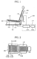
Figure 1 is a diagram schematically showing the state
where a passenger detecting apparatus according to a first
embodiment of this invention is used in a seat unit;
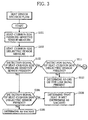
Figure 2 is a diagram schematically depicting the seat
unit in Figure 1 in a reclined state;
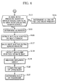
Figure 3 is a flowchart for explaining procedures of
determining the presence of a passenger or an object on a seat
unit and the build of the passenger by using the passenger
detecting apparatus according to the first embodiment of this
invention;
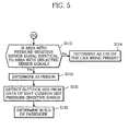
Figure 4 is a flowchart illustrating procedures
continuing from Figure 3;
Figure 5 is a flowchart illustrating procedures according
to another embodiment different from the flowchart in Figure
4;
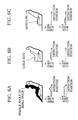
Figures 6A through 6C are diagrams for explaining
(Example 1) of this invention;
Figures 7A and 7B are diagrams for explaining (Example 2)
of this invention;
Figures 8A and 8B are diagrams for explaining (Example 3)
of this invention;
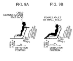
Figures 9A and 9B are diagrams for explaining (Example 4)
of this invention;
Figures 10A and 10B are diagrams for explaining the
structure of a passenger detecting apparatus used in (Example
5) of this invention;
Figures 11A and 11B are diagrams for explaining (Example
5) of this invention;
Figure 12 is a diagram schematically showing a passenger
detecting apparatus according to a second embodiment of this
invention;
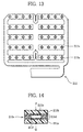
Figure 13 is a diagram partially illustrating a seat-cushion
pressure-sensitive sensor which is used in the
passenger detecting apparatus in Figure 12;
Figure 14 is a cross-sectional view of sensor elements
which constitutes the seat-cushion pressure-sensitive sensor
in Figure 13;
Figure 15 is a diagram illustrating a decision flow of
the passenger detecting apparatus according to the second
embodiment of this invention;
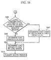
Figure 16 is a flowchart illustrating procedures
continuing from Figure 15;
Figure 17 is a diagram schematically showing the
passenger detecting apparatus which relates to the second
embodiment of this invention;
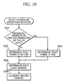
Figure 18 is a diagram illustrating a decision flow of
the passenger detecting apparatus which relates to the second
embodiment of this invention;
Figure 19 is a block diagram for explaining a passenger
detecting apparatus according to a third embodiment of this
invention;
Figures 20A and 20B are diagrams for explaining the
passenger detecting apparatus according to the third
embodiment of this invention;
Figure 21 is a diagram depicting a table stored in a
memory in Figure 19 to acquire a correction coefficient for
the load applied to feet;
Figure 22 is a flowchart illustrating a passenger
detecting routine according to the third embodiment of this
invention;
Figure 23 is a flowchart illustrating procedures
continuing from Figure 22;
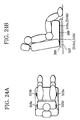
Figures 24A and 24B are diagrams for explaining a
modification of the embodiment shown in Figures 20A and 20B;
Figure 25 is a block diagram for explaining a passenger
detecting apparatus relating to the third embodiment of this
invention;
Figures 26A and 26B are diagrams for explaining the
passenger detecting apparatus relating to the third embodiment
of this invention;
Figure 27 is a cross-sectional view of sensor elements of
a film-like sensor in Figure 25;
Figure 28 is a diagram partially showing the film-like
sensor in Figure 25;
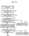
Figure 29 is a flowchart illustrating a passenger
detecting routine which relates to the third embodiment of
this invention;
Figure 30 is a flowchart illustrating procedures
continuing from Figure 29;
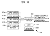
Figure 31 is a block diagram for explaining another
passenger detecting apparatus which relates to the third
embodiment of this invention;
Figures 32A and 32B are diagrams for explaining the
another passenger detecting apparatus relating to the third
embodiment of this invention;
Figure 33 is a flowchart illustrating a passenger
detecting routine which relates to the third embodiment of
this invention;
Figure 34 is a flowchart illustrating procedures
continuing from Figure 33;
Figure 35 is a block diagram for explaining a further
passenger detecting apparatus which relates to the third
embodiment of this invention;
Figures 36A and 36B are diagrams for explaining a still
further passenger detecting apparatus which relates to the
third embodiment of this invention;
Figure 37 is a block diagram for explaining a further
passenger detecting apparatus which relates to the third
embodiment of this invention;
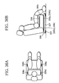
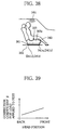
Figure 38 is a diagram for explaining the further
passenger detecting apparatus relating to the third embodiment
of this invention;
Figure 39 is a diagram depicting a table stored in a
memory to acquire a correction coefficient for the load that
is applied to the feet from the position of the head of a
passenger in another passenger detecting apparatus relating to
the third embodiment of this invention;
Figure 40 is a flowchart illustrating another passenger
detecting routine which relates to the third embodiment of
this invention;
Figure 41 is a flowchart illustrating procedures
continuing from Figure 40;
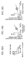
Figures 42A through 42C are diagrams showing a
relationship between the posture of a passenger on a seat and
the correction coefficient of the load applied to the feet;
Figures 43A through 43C are diagrams showing a
relationship between the posture of a passenger on a seat and
the correction coefficient of the load applied to the feet;
Figures 44A through 44C are diagrams showing a
relationship between the posture of a passenger on a seat and
the correction coefficient of the load applied to the feet;
Figures 45A through 45C are diagrams showing a
relationship between the posture of a passenger on a seat and
the correction coefficient of the load applied to the feet;
Figure 46 is a diagram showing load sensors and a
passenger detecting apparatus installed in a seat;
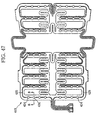
Figure 47 is a general diagram showing the general
structure of the passenger detecting apparatus shown in Figure
46;
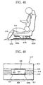
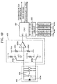
Figure 48 is a B-B cross-sectional view of the passenger
detecting apparatus shown in Figure 47;
Figure 49 is a structural diagram exemplifying the
structure of a passenger detecting apparatus according to this
invention which uses the sensors shown in Figure 46;
Figure 50 is a flowchart for explaining the operation of
the passenger detecting apparatus shown in Figure 49; and
Figure 51 is a diagram showing load sensors installed in
a seat.
Best Mode for Carrying Out the Invention
A passenger detecting apparatus according to the first
embodiment of the present invention will now be described with
reference to the accompanying drawings.
As shown in Figure 1, a passenger detecting apparatus 110
according to the first embodiment of this invention comprises
a dielectric sensor 111 and a pressure-sensitive sensor
(pressure sensor) 112, installed in a seat cushion 102, a
dielectric sensor 113 installed in a back rest 103, an angle
sensor 114 for measuring the angle (reclining angle) that is
formed by the seat cushion 102 and the back rest 103, and a
decision unit 117 which determines the presence of a passenger
or an object on a seat unit and determines the build of a
passenger based on the measuring results of those sensors, as
shown in Figure 1.
The measured values of the dielectric sensor 111 and the
pressure-sensitive sensor 112 on the seat cushion side are
subjected to signal processing by a seat-cushion side
measuring unit 115 which is accommodated under the seat
cushion 102 and the measured values of the dielectric sensor
113 and the angle sensor 114 on the back rest side are
subjected to signal processing by a back-rest side measuring
unit 116 which is housed in the back rest 103, and they are
both transmitted to the decision unit 117.
The dielectric sensor 111 and the pressure-sensitive
sensor 112 installed in the seat cushion 102 are intervened in
a stacked state between the seat cushion and the seat fabric.
The dielectric sensor 111 detects the presence or absence
of a passenger by using the phenomenon that the output current
of radiated waves changes according to the presence/absence of
a dielectric substance, and comprises a plurality of
dielectric sensor elements 111a, 111b, ... arranged
independently and in parallel from the front of the seat
cushion 102 toward the rear, as shown in Figure 2. The
dielectric sensor elements 111a, 111b, ... are comprised of a
combination of transmission antennae and reception antennae,
and transmit a high-frequency wave from each transmission
antenna and detects a current produced in each reception
antenna. The currents detected by the individual elements
111a, 111b, ... are associated with the layout positions of
the individual elements 111a, 111b, ... in the decision unit
117 to obtain the range where the passenger's buttocks lie,
and the seating position (seating state) of the passenger on
the seat cushion 102 is determined.
That is, an output current I of each of the dielectric
sensor elements 111a, 111b, ... is compared with a
predetermined threshold value, the rear-end position of the
passenger's buttocks on the seat cushion 102 is acquired from
the layout positions of the individual elements 111a, 111b, ...
and the seating position of the passenger is determined from
this rear-end position.
The pressure-sensitive sensor 112 located under the
dielectric sensor 111 is formed by printing conductive ink, to
which conductive particles, such as carbon powder, silver
powder or copper powder are added, on a PET film by known
printing means and detects the presence of a passenger or an
object on the seat cushion 102 by using the phenomenon that a
contact resistance changes in accordance with the pressing
force.
As shown in Figure 2, this pressure-sensitive sensor 112,
like the dielectric sensor 111, comprises a plurality of
independent pressure- sensitive sensor elements 112a, 112b, ...
arranged in the front-rear direction in the seat cushion 102.
Voltage values according to the pressures for the individual
pressure- sensitive sensor elements 112a, 112b, ... are
detected, the detection results are subjected to signal
processing in the seat-cushion side measuring unit 115, the
peak value of an output voltage P is acquired in the decision
unit 117, and the center position (ischial tuberculum
position) of the buttocks of the passenger on the seat cushion
102 is acquired from the layout position of the pressure-sensitive
sensor element that has produced this peak value.
For the pressure-sensitive sensor 112, a device using a
pressure-sensitive rubber or a load cell may be used instead
of the pressure-sensitive ink. Because the detection
principles of the dielectric sensor 111 and the pressure-sensitive
sensor 112 are quite different from each other as
mentioned above, both sensors, even arranged in the seat
cushion 102 in a stacked state, do not adversely affect each
other with respect to the output characteristics.
A temperature sensor may be used in place of the
pressure-sensitive sensor 112 to detect the seating state.
That is, a plurality of elements which detect a change in
temperature may be arranged in the front-rear direction in the
seat cushion, so that the rear-end position of, for example,
the buttocks is detected from a difference in temperature
between the portion where the passenger's buttocks contact and
the portion where they do not, and the seating state of the
passenger is determined based on the position.
The dielectric sensor 113 installed in the back rest 103
uses a dielectric sensor similar to the dielectric sensor 111
installed in the seat cushion 102. This dielectric sensor 113,
as schematically illustrated in Figure 2, is constructed by
arranging dielectric sensor elements 113a, 113b, ..., which
are comprised of a combination of transmission antennae and
reception antennae, at the back of the fabric in the up-down
direction of the back rest 103 in parallel to one another.
The output currents from the individual dielectric sensor
elements 113a, 113b, ... are subjected to signal processing by
the back-rest side measuring unit 116 as in the seat-cushion
side measuring unit 115 and the area where the back of the
passenger contacts the back rest 103 is acquired by the
decision unit 117. Then, the topmost position of this area is
determined as the shoulder position of the passenger.
Instead of arranging the dielectric sensor 113 in the
back rest 103, the pressure-sensitive sensor 112 as used in
the seat cushion 102 may be arranged to detect the contact
state of the passenger to the back rest 103, or a temperature
sensor may be arranged to detect the contact state of the
passenger to the back rest 103. That is, it is possible to
acquire the area where the back of a passenger is in contact
with the back rest 103 by detecting a change in the contact
pressure of the passenger to the back rest 103 or a change in
the temperature of the contact portion is detected from a
plurality of pressure-sensitive sensor elements or a plurality
of temperature sensor elements arranged in the back rest 103.
Because the back of the passenger does not closely
contact the seat unit 101, however, it is preferable to use
the dielectric sensor 113 that can surely detect the presence
of a human body even in the case where the human body merely
contacts the sensor. Even when the passenger takes a posture
of having the upper half body set in a slightly upright state,
therefore, the contact area of the back rest can be acquired
more accurately.
The angle sensor 114 which measures the angle defined by
the seat cushion 102 and the back rest 103 is comprised of a
tilt angle measuring unit attached to the rotary portion of
the back rest 103 as schematically illustrated in Figure 1.
In the case where seat reclining is carried out by an
electric motor as in a power adjustable seat unit, the tilt
angle of the back rest 103 may be acquired by using the output
of the encoder of the electric motor. When the backward and
forward inclination of the seat cushion 102 is adjustable, a
tilt angle measuring unit may be installed in the seat cushion
102 as in the back rest 103, so that the angle defined by the
seat cushion 102 and the back rest 103 is computed by the
back-rest side measuring unit 116 based on the outputs from
both tilt angle measuring units.
The outputs of the dielectric sensor 111 and the
pressure-sensitive sensor 112 arranged in the above-described
manner on the seat cushion side are used to determine the
presence/absence of a passenger or an object and acquire the
positional information of the buttocks of the passenger if the
passenger is seated in the decision unit 117.
When moisture is sticking on the fabric of the seat
cushion 102, the dielectric sensor 111 responds and the
pressure-sensitive sensor 112 does not, so that the decision
unit 117 can determine that moisture is sticking on the seat
cushion 102.
The output of the dielectric sensor 113 on the back rest
side is used to acquire the shoulder positional information of
a passenger in the decision unit 117 and the output of the
angle sensor 114 is also sent to the decision unit 117 via the
back-rest side measuring unit 116.
The decision unit 117, which comprises a processing unit
(CPU) 117c and a memory 117m, determines if a passenger or an
object is on the seat cushion 102 and if moisture is thereon
and determines the build of a passenger when seated on the
seat unit 101, based on before mentioned detection signals.
The decision procedures will be described below based on
the flowcharts in Figures 3 and 4.
At the same time as the decision flow starts, measurement
by the seat-cushion side pressure-sensitive sensor 112 is
performed (step S101) followed by measurement by the seat-cushion
side dielectric sensor 111 (step S102). Subsequently,
it is determined if there is a detection signal of the seat-cushion
side pressure-sensitive sensor 112 (step S103), and if
there is no detection signal of the seat-cushion side
pressure-sensitive sensor 112, it is determined if there is a
detection signal of the seat-cushion side dielectric sensor
111 (step S104). If there is no detection signal of the seat-cushion
side dielectric sensor 111, both the seat-cushion side
pressure-sensitive sensor 112 and seat-cushion side dielectric
sensor 111 have not responded so that it is determined that
neither a person nor an object is on the seat cushion 102 and
the seat is vacant (step S105). When there is the detection
signal of the seat-cushion side dielectric sensor 111, nothing
is on the seat cushion 102 but a dielectric substance exists,
so that it is determined that the seat is wet though vacant
(step S106). There may be a case where seats are wetted due
to shower or squall in an open car or the like, so that the
provision of this decision routine is very significant.
When there is the detection signal of the seat-cushion
side pressure-sensitive sensor 112, it is determined if there
is the detection signal of the seat-cushion side dielectric
sensor 111 (step S111). If the detection signal of the seat-cushion
side dielectric sensor 111 is not present, it is
determined that a child seat (CSR) which is a non-dielectric
substance, or a luggage or the like is lying on the seat
cushion 102 (step S112). When the detection signal of the
seat-cushion side dielectric sensor 111 is present, it is
determined if an area where the pressure-sensitive sensor
signal is present is identical to an area where the dielectric
sensor signal is present (step S113). As a plurality of
pressure- sensitive sensor elements 112a, 112b, ... and
dielectric sensor elements 111a, 111b, ... are arranged in the
seat cushion 102 in a stacked manner as mentioned above, it is
possible to accurately detect and compare the sensor output
areas in the seat cushion 102.
When it is determined in step S113 that both areas are
not identical or do not coincide with each other, it is
possible that, for example, the hands or legs of a child who
is sitting on a child seat are in contact with the seat
cushion 102, so that it is determined that a child seat (CSR)
or the like is on the seat cushion 102 (step S114).
When it is determined in step S113 that both areas are
identical, it is determined that a passenger is sitting on the
seat cushion 102 (step S115), and the position of the buttocks
on the seat cushion 102 is detected (step S116). This seat-cushion
buttock position may be acquired by using the
detection end position of the seat-cushion side dielectric
sensor 111 or by using the peak position of the detection
signal from the seat-cushion side pressure-sensitive sensor
112.
Subsequently, measurement by the back-rest side
dielectric sensor 113 is carried out (step S117) and the
shoulder position of the back rest is detected from this
measuring result (step S118). As a plurality of dielectric
sensor elements 113a, 113b, ... are arranged in the up-down
direction in the back rest 103 in parallel to one another as
mentioned above, this shoulder position can be acquired based
on the output end positions of those elements 113a, 113b ....
Next, the reclining angle is measured by the angle sensor
114 (step S119), and the size of the upper body of the
passenger is computed from the buttock position in step S116,
the back-rest shoulder position in step S118 and the reclining
(tilt) angle of the back rest 103 (step S120) and the build of
the passenger is determined (step S121).
The more forward is the buttock position located in
relation to the seat cushion 102, the higher is the shoulder
position located up the back rest 103 and the greater is the
reclining angle of the back rest 103, it is determined in this
step S120 that the size of the upper body is greater and it is
determined in step S121 that the build of the passenger is
larger. When the buttock position is located deep in the seat
cushion 102, the shoulder position is at the lower portion of
the back rest 103 and the reclining angle of the back rest 103
is not so large, it is determined that a child is seated on
the seat unit 101, while when the buttock position is at a
front portion of the seat cushion 102, the shoulder position
is at the upper portion of the back rest 103 and the reclining
angle of the back rest 103 is large, it is determined that an
adult of a standard size is seated on the seat unit 101. When
they are in middle, it is determined that an adult of small
build is seated on the seat unit 101.
Based on the above decision results, restraint systems
for securing passenger safety, such as an air bag, can be
activated properly.
Specifically, for example, it is possible to change the
air-bag inflation speed is changed or not to inflate the air
bag in accordance with the build of the seated person. That
is, when it is determined that an adult of small build is
seated, the air bag is inflated more slowly than that in the
case where it is determined that an adult of a standard size
is seated, and when it is determined that a child is seated,
the air bag is not inflated, thus preventing a woman of small
build or a child from being injured by the air bag when it is
activated.
Further, if the passenger detecting apparatus 110 is
installed in every passenger seat unit in a vehicle, an
airplane or the like and the aforementioned decision is made
by each passenger detecting apparatus 110, it is possible to
not only determine the vacancy of each seat unit and the
presence/absence of a luggage or the like occupying each seat
unit but also roughly and remotely grasp the ratio of adults,
children or the like in passengers seated on the individual
seat units. This can be helpful in in-vehicle (in-flight)
services or the like.
Part of the decision flow according to the above-described
embodiment may be replaced with a decision flow
shown in Figure 5 to determine the build of the passenger.
In executing the decision flow shown in Figure 5, it is
required that at least part of the pressure-sensitive sensor
122 located on the seat cushion side has pressure-sensitive
sensor elements arranged in an m x n matrix form as shown in
Figure 10 so that when a passenger is seated, the seating
state not only in the front-rear direction of the seat cushion
102 but also the widthwise direction can be detected.
According to the decision flow shown in Figure 5, the
same decision routine as performed in the above-described
embodiment until the decision flow illustrated in step S115 in
Figures 2 and 3, and when it is determined in step S115 that a
passenger is seated on the seat unit 101, the range where the
passenger's buttocks are located is detected in the widthwise
direction of the seat cushion 102 as well as in the front-rear
direction. The size of the passenger's buttocks is detected
from the number and layout positions of the matrix sensor
elements detected (step S131) and the build of the passenger
is determined from the size of the buttocks (step S132).
It is therefore possible to accurately detect the case
where a child is seated sideways as described in Example 5 to
be discussed later, the state where an adult is seated
sideways with the back rest reclined or the like, and this
decision information can be used in the proper operations of
the peripheral systems of the seat unit.
The decision results of the passenger detecting apparatus
110 according to this invention are not limited to the use in
the adequate activation of the restraint systems for securing
passenger safety, detection of vacant seats or the like, but
may be used in automatically cutting off the power when there
is no person using, for example, a home massaging machine,
automatic selection of the optimal massage menu according to
the build of the user and so forth.
When the passenger detecting apparatus 110 according to
this invention is used in a seat unit of a vehicle, various
motors for controlling the seat posture, such as a slide motor,
front and rear vertical motors, vertical head-rest moving
motor, and a lumbar support motor, may be controlled in
accordance with the build of the passenger to automatically
adjust it to the optimal seating posture, or to automatically
adjust other peripheral systems of the seat unit, such as a
room mirror and door mirrors, in accordance with the build of
the passenger (driver).
(Example 1)
With the structure of the passenger detecting apparatus
110 shown in Figure 1, when the outputs of the pressure-sensitive
sensor 112 and the dielectric sensor 111 of the seat
cushion 102 were measured in each of the case where a female
adult of small build was seated (Figure 6A), the case where a
child seat was placed on the seat cushion 102 (Figure 6B) and
the case where the seat cushion 102 was wet with moisture
(Figure 6C), the sensor output characteristics respectively
shown in Figure 6 could be measured (the relationship between
pressure P and the detection position in the upper part is the
output characteristics by the pressure-sensitive sensor 112,
and the relationship between current I and the detection
position in the lower part is the output characteristics by
the dielectric sensor 111). Based on the detection results,
it was possible to determine the state where a child seat was
placed in Figure 6B from step S103, step S111 and step S112 of
the passenger detection decision flow, to determine the state
where the seat cushion 102 was wetted with moisture in Figure
6C from step S103, step S104 and step S106 and to easily
determine the state where an adult of small build was seated
from step S103, step S111, step S113 and step S115 to step
S121.
(Example 2)
Likewise, with the structure of the passenger detecting
apparatus 110 shown in Figure 1, the outputs of the dielectric
sensor 111 of the seat cushion 102 and the dielectric sensor
113 of the back rest 103 were measured in each of the case
where a female adult of small build was seated (Figure 7A) and
the case where a child was seated (Figure 7B) and the sensor
output characteristics respectively shown in Figure 7 could be
measured (the relationships between the current I of the
dielectric sensor and the detection position on the seat
cushion side and the back rest side are respectively shown).
As the end portions of the output current I (the white-dot
portions in the diagrams) were acquired respectively as the
buttocks and shoulder of the passenger, it was detected that
the buttocks of a female adult of small build were located
slightly further forward in relation to the seat cushion 102
than the buttocks of a child and the shoulder of a female
adult of small build were located higher on the back rest 103
than the shoulder of a child. Based on those detection
results, it was possible to easily determine that an adult of
small build was seated in the case of Figure 7A and that a
child was seated in the case of Figure 7B through step S119 to
step S121 of the passenger detection decision flow.
(Example 3)
Likewise, with the structure of the passenger detecting
apparatus 110 shown in Figure 1, the outputs of the pressure-sensitive
sensor 112 of the seat cushion 102 and the
dielectric sensor 113 of the back rest 103 were measured in
each of the case where a female adult of small build was
seated with the buttocks shifted frontward (Figure 8A) and the
case where a child was seated (Figure 8B) and the sensor
output characteristics respectively shown in Figure 8 could be
measured (the relationship between the pressure P and the
detection position on the seat cushion side is the output
characteristics by the pressure-sensitive sensor 112, and the
relationship between the current I and the detection position
on the seat cushion side is the output characteristics by the
dielectric sensor 113). Although the end portions of the
output current I of the dielectric sensor 113 indicating the
position of the shoulder of the passenger (the white-dot
portions in the diagrams) were both detected to be
substantially coincide with each other, the peak position of
the output voltage P of the pressure-sensitive sensor 112
indicating the position of the passenger's buttocks for a
female adult of small build was detected to be considerably
forward in relation to the seat cushion 102 as compared with
the case of a child. Based on those detection results, it was
possible to easily determine that an adult of small build was
seated in the case of Figure 8A and that a child was seated in
the case of Figure 8B through step S119 to step S121 of the
passenger detection decision flow.
(Example 4)
Likewise, with the structure of the passenger detecting
apparatus 110 shown in Figure 1, the outputs of the pressure-sensitive
sensor 112 of the seat cushion 102 and the
dielectric sensor 113 of the back rest 103 were measured in
the state where a child was leaning against the back rest 103
(Figure 9A) and the case where a female adult of small build
was seated (Figure 9B) and the sensor output characteristics
respectively shown in Figures 9A and 9B could be measured (the
relationships between the pressure P and the detection
position on the seat cushion side is the output
characteristics by the pressure-sensitive sensor 112 and the
relationships between the current I and the detection position
on the seat cushion side is the output characteristics by the
dielectric sensor 113).
Although the end portions of the output current I of the
dielectric sensor 113 indicating the position of the
passenger's shoulder (the white-dot portions in the diagrams)
were detected slightly higher than the seat cushion 103 for
the case of a child than for the case of a female adult of
small build, the peak position of the output voltage P of the
pressure-sensitive sensor 112 indicating the position of the
passenger's buttocks was detected at a deeper portion on the
seat cushion 102 for the case of a child than for a female
adult of small build. Based on those detection results, it
was possible to determine that a child was seated in the case
of Figure 9A and that an adult of small build was seated in
the case of Figure 9B through step S119 to step S121 of the
passenger detection decision flow.
(Example 5)
A pressure-sensitive sensor 122 of the seat cushion 102
used in this embodiment had five belt-like pressure-sensitive
sensors arranged in parallel at the front portion of the seat
cushion and had 6 x 8 spot-like pressure-sensitive sensors
arranged in a matrix form at a rear portion of the seat
cushion as shown in Figures 10A and 10B. For a dielectric
sensor 121 of the seat cushion 102, a dielectric sensor 123 of
the back rest 103 and a tilt angle sensor (not shown), sensors
which have the same structures as those shown in Figure 1 were
used.
Using this passenger detecting apparatus 120, the outputs
of the pressure-sensitive sensor 122 of the seat cushion 102
and the dielectric sensor 123 of the back rest 103 were
measured in the state where a child was seated sideways
(Figure 11A) and the case where a woman of small build was
seated (Figure 11B), and the sensor output characteristics
respectively shown in Figures 11A and 11B could be measured
(the relationships between the pressure P and the detection
position on the seat cushion side is the output
characteristics by the pressure-sensitive sensor 122, below
which the pressure distribution of the seat cushion is
illustrated, and the relationships between the current I and
the detection position on the seat cushion side is the output
characteristics by the dielectric sensor 123).
It was possible to easily acquire the size of the
passenger's buttocks occupying the seat cushion from the
pressure distribution of the spot-like pressure-sensitive
sensors arranged in a matrix form. Through step S131 and step
S132 shown in Figure 5, therefore, it was possible to easily
determine that a child is seated in the case of Figure 11A and
that an adult of small build is seated in the case of Figure
11B.
That is, according to this embodiment, specifically
designing the structure of the sensors arranged in the seat
cushion 102 could make it possible to determine the
presence/absence of a passenger or an object on the seat
cushion 102 and the build of the passenger.
The above results of the embodiment showed that the use
of the passenger detecting apparatus 110 according to this
invention made it possible to discriminate the case where a
child seat or the like was placed on the seat cushion 102 and
the case where moisture was sticking thereon, and easily
determine whether an adult of small build is seated besides an
adult of a standard size, so that, for example, the air-bag
inflation speed could be slowed or the air-bag inflation could
be stopped in accordance with the build of the passenger.
A description will now be given of a passenger detecting
apparatus according to the second embodiment of this invention
with reference to the accompanying drawings.
As shown in Figure 12, a passenger detecting apparatus
210 according to the second embodiment of this invention
comprises a seat-cushion pressure-sensitive sensor (first
detection means) 211 for detecting the distribution of the
load that is applied to a seat cushion 201 of a vehicle, load
sensors (second detection means) 212a and 212b for detecting
the weight of the seat of the vehicle and the load that is
applied to the entire seat, and a processing section 213 for
classifying a passenger seated on the seat based on the
detection results of the seat-cushion pressure-sensitive
sensor 211 and the load sensors 212.
A film-like pressure sensor is used for the seat-cushion
pressure-sensitive sensor 211. As shown in Figure 13, the
film-like pressure sensor has a plurality of pressure-sensitive
sensor elements 211a laid in a sheet form and is
located in the vicinity of the fabric of the seat cushion 201
so that it easily receives the load from a passenger.
As shown in Figure 14, the pressure-sensitive sensor
element 211a has an insulating layer 211d formed of an
adhesive layer of a predetermined thickness sandwiched by
insulating plastic films 211b and 211c of PET or the like.
Conductive layers 211e and 211f which have metal foils of a
predetermined shape adhered or conductive paint printed in a
predetermined shape into a circuit pattern are adhered onto
the insulating plastic films 211b and 211c in such a way as to
face each other at a given distance. As pressure is applied
to the pressure-sensitive sensor element 211a from the
directions of arrows P and Q, the conductive layers 211e and
211f contact each other and this contact is electrically
detected to detect the pressure applied to the pressure-sensitive
sensor element 211a.
As such pressure-sensitive sensor elements 211a are
arranged in a matrix form as partially shown in Figure 13, it
is possible to detect the area of the buttocks of the
passenger seated on the seat cushion 201, the area of a child
seat in contact with the seat cushion 201 or the area of a
luggage in contact with the seat cushion 201 from the outputs
of the individual pressure-sensitive sensor elements 211a of
the seat-cushion pressure-sensitive sensor 211.
Electric capacitance type pressure sensors are used for
the load sensors 212a and 212b. As shown in Figure 12, the
load sensors 212a and 212b are placed under support portions
203 and 204 for supporting the entire seat on a floor 202, so
that the individual load sensors 212a and 212b measure the
weight of the seat acting on the respective support portions
and the weight of the passenger acting on the entire seat and
send the output signals to the processing section 213. Note
that distortion gauges may be used to measure the load in
place of the electric capacitance type pressure sensors.
The processing section 213 has a CPU 213c and memory 213m.
Based on the detection results of the seat-cushion pressure-sensitive
sensor 211, the CPU 213c determines whether a
passenger is seated, a child seat is placed or a luggage is
lying on the seat cushion 201, determines if there is a change
in the detection area of the seat-cushion pressure-sensitive
sensor 211, i.e., if the barycenter of the passenger is
shifted on the seat, and performs classification of each
weight of the passengers on the seat. The memory 213m stores
a threshold value pattern for determining the presence/absence
of a passenger on the seat, the presence/absence of a child
seat, the presence/absence of a luggage and so forth based on
the detection results of the seat-cushion pressure-sensitive
sensor 211, and is storing threshold values or the like for
allowing the CPU 213c to execute classification of each weight
of the passengers on the seat.
This passenger detecting routine will be discussed in
detail below based on flowcharts illustrated in Figures 15 and
16.
First, the load that is applied to the seat cushion 201
is measured by the seat-cushion pressure-sensitive sensor 211
(step S201), and it is determined if there is a load applied
to the seat cushion 201 (step S202). When there is no load
applied to the seat cushion 201, it is determined that the
seat is vacant (step S203). This decision result is
transmitted to a control unit for the seat's peripheral
systems to inhibit, for example, an air bag or the like from
being activated unnecessarily. When there is an output from
the seat-cushion pressure-sensitive sensor 211, it is detected
from the output of the seat-cushion pressure-sensitive sensor
211 if the barycenter is shifted (step S204). When there is
no barycenter shift, it is determined that a luggage is on the
seat (step S205). When there is a barycenter shift, the CPU
213c determines if this load distribution pattern is close to
the load distribution pattern of a child seat (CRS) by
comparing it with the threshold value pattern in the memory
213m (step S206). When they are close to each other, it is
determined that a child seat is on the seat (step S207). In
this case, as barycenter shifting on the seat has already been
detected in step S204, it is simultaneously determined that an
infant or a child is in the child seat.
When the load distribution pattern is not close to the
load distribution pattern of the child seat, it is determined
that a passenger is directly seated on the seat (step S208).
Next, the load that is applied on the whole seat is
measured by the load sensors 212 (step S209). As the load
sensors 212 are placed under support portions 203 and 204 that
support the seat frame (not shown) on the floor 202, they can
measure the load that acts on the entire seat including the
weight of the seat so that the load acting on the entire seat
can be measured accurately.
When electric capacitance type pressure sensors are used
for the load sensors 212, the initial values of the load
sensors are likely to drift due to the influence of the
temperature or the like. However, the drifting of the output
value can be prevented by regularly correcting the initial
values by using the occasion when the output of the seat-cushion
pressure-sensitive sensor 211 is zero, i.e., when no
passenger is seated on the seat.
Subsequently, classification of each weight of the seated
persons is carried out (step S210). This can be accomplished
easily as the CPU 213c compares the value of the load applied
to the seat, obtained from the load sensors 212, with the
threshold value stored in the memory 213m.
As one example, the passenger on the seat is classified
into a weight class of an adult of a standard size, a weight
class of a woman of small build and a weight class of a child
from the value of the load applied to the seat and even if it
is determined as the weight class of a child, when it is
determined in step S207 that a child seat is on the seat, it
is determined that a child is not directly seated on the seat
but the class is such that an infant is seated on the seat via
the child seat.
Because the passenger detecting apparatus according to
the second embodiment of this invention can accurately
classify a passenger on the seat as apparent from the above,
it is possible to, for example, normally activate an air bag
when the weight of the passenger on the seat belongs to the
weight class of an adult of a standard size, to active the air
bag more slowly than the normal air-bag inflation speed when
the passenger's weight belongs to the weight class of a woman
of small build and to inhibit the inflation of the air bag
when the passenger's weight belongs to the weight class of a
child. Even when the weight of the passenger on the seat
belongs to the weight class of a child, if it is determined
that the weight belongs to the weight class of an infant
seated on the seat via a child seat, the seat's peripheral
systems, such as a door lock, are activated automatically so
as to prevent the infant from carelessly opening the door.
A description will now be given of a passenger detecting
apparatus which relates to the second embodiment of this
invention.
Like reference symbols are given to the components which
are the same as the corresponding components of the above-described
embodiment, and the detailed description thereof is
omitted.
As shown in Figure 17, a passenger detecting apparatus
220 which relates to the second embodiment of this invention
comprises a child-seat detection antenna (first detection
means) 221 located in the seat cushion 201 of a vehicle, load
sensors (second detection means) 222a and 222b for detecting
the weight of a seat of the vehicle and the load that is
applied to the entire seat, and a processing section (decision
means) 223 for classifying a passenger seated on the seat
based on the detection results of the detection antenna 221
and the load sensors 222.
The child-seat detection antenna 221 detects a tag 206
attached to a child seat 205 in a non-contact manner, and is
attached under the seat fabric so as to easily detect the tag
206.
Electric capacitance type pressure sensors similar to the
load sensors 212 used in the passenger detecting apparatus 210
according to the second embodiment are used for the load
sensors 222, which are placed under the support portions 203
and 204 that support the seat frame (not shown) on the floor
202 and measure the load that is applied to the entire seat
including the weight of the seat.
The processing section 223 has a CPU 223c and memory 223m.
Based on the decision flow which will be illustrated below in
detail, the CPU 223c determines if the child seat 205 is on
the seat and classifies the weight of the passenger on the
seat from the detection result of the child-seat detection
antenna 221. Stored in the memory 223m is the threshold value
pattern that is needed for the CPU 223c to classify the
passenger on the seat based on the detection results of the
load sensors 222.
This passenger detecting routine will be discussed below
in detail based on a flowchart illustrated in Figure 18.
First, the child-seat detection antenna 221 detects the
tag 206 of the child seat to discriminate if the child seat
(CRS) is on the seat (step S221), and when there is no output
from the detection antenna 221, it is determined that there is
no child seat (step S222). When there is an output from the
detection antenna 221, on the other hand, it is determined
that there is a child seat (step S223). After those decisions
are made, the load sensors 222 measure the load that is
applied to the entire seat (step S224).
In the case where electric capacitance type sensors are
used for the load sensors 222, drifting of the output value
can be prevented as the CPU 223c corrects the initial values
of the load sensors 222 when a passenger is not seated, for
example, upon detection of when the passenger opens the door
and gets out of the vehicle.
Subsequently, classification of each weight of the seated
persons is carried out (step S225). This can be accomplished
as the CPU 223c compares the value of the load applied to the
entire seat, obtained from the load sensors 222, with the
threshold value stored in the memory 223m, as done by the
passenger detecting apparatus 210 according to the second
embodiment.
Specifically, the passenger on the seat is classified
into a weight class of an adult of a standard size, a weight
class of a woman of small build and a weight class of a child
from the value of the load applied to the seat and even if it
is determined as the weight class of a child, when it is
determined in step S223 that a child seat is on the seat, it
is determined that a child is not directly seated on the seat
but the class is such that an infant is seated on the seat via
the child seat.
The passenger detecting apparatus 220 which relates to
the second embodiment of this invention can detect the
presence/absence of a child seat and classify a passenger on
the seat by a simpler decision flow. Accordingly, it is
possible to activate an air bag normally or at a slower air-bag
inflation speed or inhibit it from being inflated in
accordance with the weight of a passenger on the seat as in
the case of the passenger detecting apparatus 210 of the
second embodiment. Further, as an infant seating on the seat
via a child seat is detected reliably, it is possible to
automatically activate the seat's peripheral systems, such as
a door lock, so as to prevent the infant from carelessly
opening the door.
As different from the passenger detecting apparatus
according to the above-described embodiment, a combination of
a dielectric sensor and a pressure sensor may be used in the
first detection means. For example, attaching a dielectric
sensor to the back rest of a seat can allow a child seat on
the seat to be distinguished from a booster seat.
The second detection means can use any sensor, such as a
piezoelectric type sensor, pressure-sensitive rubber or
pressure-sensitive ink, in place of the electric capacitance
type sensor, as long as it can accurately measure the weight.
Needless to say that instead of the decision flow for the
passenger detecting apparatus according to the above-described
embodiment, various types of decision flows can be adapted
without departing from the object of this invention.
A description will now be given of a passenger detecting
apparatus 310 according to the third embodiment of this
invention with reference to the accompanying drawings.
As shown in Figures 19, 20A and 20B, the passenger
detecting apparatus 310 according to the third embodiment of
this invention comprises four load sensors 311a-311d arranged
between a seat frame 301 and a floor 302, and a processing
section 312 which detects a passenger on the seat based on the
outputs of the load sensors 311.
Electric capacitance type pressure sensors are used for
the load sensors 311, and are placed under support portions
which support the seat frame 301 to the floor 302 as shown in
Figure 20B. Each load sensor 311 measures the weight of a
seat 303 that acts on the associated support portion and the
weight of a passenger that is applied to the seat 303, and
sends the output signal to the processing section 312. The
load may be measured by using a distortion gauge instead of
the electric capacitance type pressure sensor.
The processing section 312 has a memory 312m and CPU 312c.
The memory 312m is storing threshold values for discriminating
the weight of an adult of a standard size, the weight of a
woman of small build and the weight of a child, and the
correlation between the barycenter position of a passenger on
the seat and the correction coefficients for the load that is
applied to the feet of the passenger. The CPU 312c has
functions of acquiring the barycenter position of a passenger
on the seat, acquiring the load applied to the feet of the
passenger from the weight of the passenger acting on the seat,
correcting the load based on the barycenter position of the
passenger on the seat and accurately estimating the weight of
the passenger.
A table stored in the memory 312m, which shows the
correlation between the barycenter position and the correction
coefficients for the load that is applied to the feet, is
designed in such a way that as the barycenter position of the
passenger on the seat lies forward on the seat, the correction
coefficient for the load applied to the feet becomes greater,
as shown in Fig.21. As the passenger is seated further forward
on the seat, for example, a more weight is applied to the feet,
so that it is possible to adequately estimate, from this
correction coefficient, the load that is applied to the feet
of the passenger, other than the weight of the passenger
applied to the seat, and thus accurately estimate the weight
of the passenger.
Specifically, the load that is applied to the feet of the
passenger reaches 30% of the entire weight of the passenger at
a maximum. More specifically, the load that is applied to the
feet of the passenger becomes about 20 to 25% of the entire
weight when the passenger is seated with a standard posture,
depending on the state of the seat, and becomes about 30% of
the entire weight at a maximum when the passenger is seated
too forward. That is, as the passenger is seated deeper on
the seat, the ratio of the load applied to the feet of the
passenger decreases significantly with respect to the entire
weight of the passenger. It is therefore possible to estimate
the load applied to the feet of the passenger by using this
correction coefficient, and thus accurately estimate the
weight of the passenger.
The CPU 312c can acquire the barycenter of the passenger
by comparing the output values of the load sensors 311a, 311b
at the front portion of the seat with the output values of the
load sensors 311c, 311d at the rear portion of the seat. That
is, the output values of the load sensors 311a, 311b at the
front portion of the seat become greater than the output
values of the load sensors 311c, 311d at the rear portion of
the seat when the passenger is seated at the front of the seat,
and vice versa when the passenger is seated rearward on the
seat, so that the barycenter of the passenger on the seat can
be acquired by using the output difference. Note that an
elastic member, such as a rubber bushing, may be interposed
between the seat frame 301 and the floor 302 where the load
sensors 311 are arranged. This causes the output values of
the load sensors 311 at the front and back portions of the
seat to differ greatly according to the seating position of
the passenger, thus ensuring easier acquisition of the
barycenter.
The CPU 312c also acquires the weight of the passenger
applied to the seat 303 from the output values of the four
load sensors 311, acquires the correction coefficient for the
load that is applied to the feet of the passenger from the
barycenter position, obtained in the above-described manner,
by referring to the correction coefficient table in the memory
312m, and accurately estimates the weight of the passenger
based on those values. Even if the weight of the passenger
applied to the seat 303 is the same, therefore, the weight is
estimated heavier when the passenger is seated forward on the
seat than when the passenger is seated rearward on the seat.
This passenger detecting routine will be discussed below
in detail based on flowcharts illustrated in Figures 22 and 23.
First, the load that is applied to each load sensor 311
is measured in response to an external drive signal (step
S301). Although the initial values of the load sensors are
likely to drift due to the influence of the temperature or the
like when electric capacitance type pressure sensors are used
for the load sensors, the CPU may correct the initial values
of the load sensors upon detection of the time when no
passenger is seated on the seat, e.g., when the passenger
opens the door and gets out of the vehicle.
Subsequently, the CPU computes the weight of the
passenger applied to the seat (step S302). This is
accomplished by adding the output values of the individual
load sensors 311 and subtracting the weight of the seat itself
prestored in the memory 312m from the resultant value. It
should be noted that the weight of the seat itself is acquired
by the load sensors 311 when no passenger is seated to use it.
Next, the CPU determines if the entire weight applied to
the seat is equal to or less than a predetermined threshold
value (step S303). When it is equal to or less than the
predetermined threshold value, it is determined that the seat
is vacant (step S304) and this decision signal is sent out.
This decision signal is transmitted to the seat's peripheral
ancillaries, e.g., the air bag system, as passenger build
information to inhibit those ancillaries from being activated
unnecessarily.
When the entire weight applied to the seat exceeds the
predetermined threshold value, the barycenter position of the
passenger on the seat is detected from the outputs of the
individual load sensors by the above-described method (step
S305).
Subsequently, it is determined if the detected barycenter
position lies too forward beyond the allowable range (step
S306). When it lies too forward, it is determined that the
passenger is seated forward on the seat (step S307) and this
decision signal is sent out as passenger build information.
Based on this decision signal, it is possible to give a
warning to the effect that if a peripheral ancillary of the
seat, e.g., the air bag system, is activated, for example, the
face of the passenger may be injured.
When the detected barycenter position does not lie too
forward, it is determined that the seating position of the
passenger lies within the allowable range and the correction
coefficient for the load that is applied to the feet of the
passenger is acquired from this barycenter position by
referring to the correction coefficient table in the memory
312m (step S308). Then, the load that is applied to the feet
of the passenger is estimated from the entire weight applied
to the seat and this correction coefficient, and the entire
weight applied to the seat is added to this value to estimate
the weight of the passenger (step S309).
Next, it is determined if the estimated passenger's
weight is equal to or greater than the weight of an adult of a
standard size (step S310). When it is equal to or greater
than the weight of an adult of a standard size, it is
determined that the passenger seated on the seat is an adult
of a standard size (step S311) and this decision signal is
sent out as passenger build information.
Based on this decision signal, a peripheral ancillary of
the seat, e.g., the air bag system, is activated at the normal
inflation speed.
When the estimated passenger's weight does not exceed the
weight of an adult of a standard size, it is determined if
this weight is equal to or greater than the weight of a woman
of small build (step S312). When this weight is equal to or
greater than the weight of a woman of small build, it is
determined that the passenger seated on the seat is a woman of
small build (step S313) and this decision signal is sent out
as passenger build information.
Based on this decision signal, a peripheral ancillary of
the seat, e.g., the air bag system, is activated at a
inflation speed slower than the usual speed, thus preventing
the passenger from being injured by the inflation of the air
bag.
When the estimated weight does not exceed the weight of a
woman of small build, it is determined that the passenger
seated on the seat is a child or an infant (step S314) and
this decision signal is sent out as passenger build
information.
Based on this decision signal, the activation of a
peripheral ancillary of the seat, e.g., the air bag system, is
inhibited, thus preventing the passenger from being injured by
the inflation of the air bag.
Specifically, in the case of a standard 6-year old child
(height of 119 cm, weight of 24 kg) and a woman of small build
(height of 150 cm, weight of 50 kg), when the decision is
determined from the detected barycenter position that the
passenger is seated forward, the maximum value of the load
that is applied to the feet of the passenger becomes about 30%
of the passenger's weight, so that the weight applied to the
feet of the woman of small build becomes 15 Kg and the weight
applied to the seat of the woman of small build acting on the
seat may be determined as 35 kg at a minimum. Meanwhile, the
weight of a heavy child seat is about 10 kg, and when this
child seat is used, the weight of the standard 6-year old
child is 34 kg. With 35 kg taken as the threshold value for
determining if it is a woman of small build or a child, it is
possible to reliably determine a woman of small build or a
child.
As apparent from the above, the passenger detecting
apparatus according to the third embodiment of this invention
can accurately determine not only the presence/absence of a
passenger on the seat but also the type (build) and the
seating posture of the passenger using this decision result,
therefore, it is possible to adequately activate the seat's
peripheral ancillaries, such as the air bag system.
As different from the above-described embodiment, as
shown in Figures 24A and 24B, four load sensors 315a-315d may
be placed between seat rails 307 and a seat mounting portion
306 on the seat rails. This structure makes a change in the
barycenter position of the passenger in accordance with a
change in the seating position of the passenger greater than
the one in the above-described embodiment (increases the
dynamic range), so that the barycenter of the passenger on the
seat can be detected accurately without significantly
depending on the position of a seat 308 with respect to the
seat rails 307.
A description will now be given of a passenger detecting
apparatus which relates to the third embodiment of this
invention.
Like reference symbols are given to the components which
are the same as the corresponding components of the third
embodiment, and the detailed description thereof is omitted.
As shown in Figures 25, 26A and 26B, a passenger
detecting apparatus 320 which relates to the third embodiment
of this invention comprises four load sensors 321a-321d placed
between the seat mounting portion 306 and the seat rails 307,
a film-like sensor 323 provided in a seat cushion 308s, and a
processing section 322 which detects a passenger on the seat
based on the outputs of those sensors.
Electric capacitance type pressure sensors are used for
the load sensors 321 as per the above-described embodiment,
and the initial values are regularly corrected by using the
occasion when the output of the film-like sensor 323 is zero,
i.e., when no passenger is seated on the seat.
The film-like pressure sensor 323 has a plurality of
pressure-sensitive sensor elements 324 laid in a sheet form
and is located in the vicinity of the fabric of the seat
cushion 308s so that it easily receives the load from a
passenger.
As shown in Figure 27, the pressure-sensitive sensor
element 324 has an insulating layer 324c, comprising an
adhesive layer of a predetermined thickness and an insulating
plastic film or the like, sandwiched between insulating
plastic films 324a and 324b of PET or the like. Conductive
layers 324d and 324e which have metal foils of a predetermined
shape adhered or conductive paint printed in a predetermined
shape into a circuit pattern are adhered onto the insulating
plastic films in such a way as to face each other at a given
distance. With this structure, as pressure is applied to the
pressure-sensitive sensor element 324 from the directions of
arrows P and Q, the conductive layers contact each other and
this contact is electrically detected to detect the pressure
applied to the pressure-sensitive sensor element 324.
As such pressure-sensitive sensor elements 324 are
arranged in a matrix form as partially shown in Figure 28, it
is possible to detect the area of the buttocks of the
passenger seated on a seat 308 from the outputs of the
individual pressure-sensitive sensor elements 324 of the film-like
sensor 323.
The processing section 322 has a memory 322m and CPU 322c,
as per the above-described embodiment. The memory 322m is
storing the correlation between the barycenter position of the
passenger and correction coefficients for the load that is
applied to the feet of the passenger. The CPU 322c has
functions of acquiring the center position of the area of the
passenger's buttocks detected by the film-like sensor 323 and
taking it as the barycenter position of the passenger on the
seat, and functions of acquiring the weight of the passenger
applied to the seat 308 from the output values of the four
load sensors 321, acquiring the correction coefficient for the
load that is applied to the feet of the passenger from the
aforementioned barycenter position by referring to the
correction coefficient table in the memory 322m and accurately
estimating the weight of the passenger based on those values.
This passenger detecting routine will be discussed below
in detail based on flowcharts illustrated in Figures 29 and 30.
The flowcharts illustrated in Figures 29 and 30 are
approximately the same as the flowcharts illustrated in
Figures 22 and 23. The load that is applied to each load
sensor 321 is measured in response to an external drive signal
(step S321). Based on the measured values, the entire weight
applied to the seat is computed (step S322). Next, it is
determined if the entire weight applied to the seat is equal
to or less than a predetermined threshold value (step S323).
When it is equal to or less than the predetermined threshold
value, it is determined that the seat is vacant (step S324)
and this decision signal is sent out as passenger build
information. When the entire weight applied to the seat
exceeds the predetermined threshold value, the barycenter
position of the passenger on the seat is detected from the
output of the film-like sensor 323 by the above-described
method (step S325). Then, it is determined if the barycenter
position of the passenger lies too forward on the seat (step
S326). When it lies too forward, it is determined that the
passenger is seated forward on the seat (step S327) and this
decision signal is sent out as passenger build information.
Otherwise, the correction coefficient for the weight at the
feet is computed from the barycenter position by the same
method as used in the third embodiment (step S328).
Then, the weight of the passenger is estimated from the
entire weight applied to the seat and the feet-weight
correction coefficient (step S329), and it is determined if
this weight is equal to or greater than the weight of an adult
of a standard size (step S330). When the weight is equal to
or greater than the weight of an adult of a standard size, it
is determined that the passenger seated on the seat is an
adult of a standard size (step S331). When the weight is less
than the weight of an adult of a standard size, it is
determined if this weight is equal to or greater than the
weight of a woman of small build (step S332). When this
weight is equal to or greater than the weight of a woman of
small build, it is determined that the passenger seated on the
seat is a woman of small build (step S333). When the weight
is less than the weight of a woman of small build, it is
determined that the passenger seated on the seat is a child or
an infant (step S334). And, those decision results are sent
out as passenger build information.
Based on the decision signal, a peripheral ancillary of
the seat, e.g., the air bag system, is activated at the proper
inflation speed when needed, thus preventing the passenger
from being injured by the inflation of the air bag.
As pressure-sensitive sensors are used, the width of the
buttocks of a passenger in a sitting state can be measured.
As the width of the buttocks of a passenger in a sitting state
is statistically known to be proportional to the weight, it is
possible to avoid a decision error in a special case of no
load applied to the feet such as the case of a child whose
feet do not reach the floor or the case of an adult who is
sitting with the feet up, by computing the estimated weight of
the passenger from the width of the buttocks of the passenger
in a sitting state, comparing it with the weight value
computed in the aforementioned correlation and using a lighter
one.
A description will now be given of a further passenger
detecting apparatus which relates to the third embodiment of
this invention.
Like reference symbols are given to the components which
are the same as the corresponding components of the above-described
embodiment, and the detailed description thereof is
omitted.
As shown in Figures 31, 32A and 32B, a further passenger
detecting apparatus 330 which relates to the third embodiment
of this invention comprises four load sensors 331a-331d placed
between the seat mounting portion 306 and the seat rails 307,
a seat position sensor 333 which detects a position of the
seat 308 on the seat rails 307 and a processing section 332
which detects a passenger on the seat based on the outputs of
those sensors.
Load sensors similar to those of the above-described
embodiment are used as the load sensors 331. From the
barycenter position of the passenger on the seat acquired by
the four load sensors 331 and the position of the seat 308 on
the seat rails 307 detected by the seat position sensor 333, a
CPU 332c in the processing section detects the barycenter
position of the passenger with respect to the seat rails 307,
so that the forward seating of the passenger with respect to
the seat rails 307 can be detected reliably.
The processing section 332 has a memory 332m identical to
the one in the above-described embodiment and the CPU 332c.
The CPU 332c has functions of acquiring the barycenter
position of the passenger with respect to the seat rails 307
detected by the load sensors 331 and the seat position sensor
333, acquiring the load applied to the feet of the passenger,
correcting it based on the barycenter position of the
passenger and accurately estimating the weight of the
passenger as per the above-described embodiment.
This passenger detecting routine will be discussed below
in detail based on flowcharts illustrated in Figures 33 and 34.
The flowcharts illustrated in Figures 33 and 34 are
approximately the same as the above-described flowcharts. The
load that is applied to each load sensor 331 is measured in
response to an external drive signal (step S341). Based on
the measured values, the entire weight applied to the seat is
computed (step S342). Then, it is determined if the entire
weight is equal to or less than a predetermined threshold
value (step S343). When it is equal to or less than the
predetermined threshold value, it is determined that the seat
is vacant (step S344) and this decision signal is sent out as
passenger build information. When the entire weight exceeds
the predetermined threshold value, the barycenter position of
the passenger on the seat is detected from the outputs of the
individual load sensors 331 by the same method as used in the
third embodiment (step S345). Further, the position of the
seat on the seat rails is detected by the seat position sensor
333 and the barycenter position of the passenger with respect
to the seat rails is detected from this detection result (step
S346).
Subsequently, it is determined if the barycenter position
lies considerably forward in relation to the seat rails (step
S347). When the barycenter position lies considerably forward
in relation to the seat rails, it is determined that the
passenger is seated forward on the seat (step S348) and this
decision signal is sent out as passenger build information.
As the passenger detecting apparatus according to this
embodiment detects the barycenter position of the passenger
with respect to the seat rails by using the output of the seat
position sensor 333, it is possible to accurately determine
whether the forward seating state is in a range allowable in
relative positional relation with the seat rails or is too
forward to be allowed.
When the barycenter position is not considerably forward
in relation to the seat rails, the correction coefficient for
the weight at the feet is computed from the barycenter
position acquired from the individual load sensors by the same
method as done in the first embodiment (step S349).
Then, the weight of the passenger is estimated from the
weight of the passenger applied to the seat and the feet-weight
correction coefficient (step S350), and it is
determined if this weight is equal to or greater than the
weight of an adult of a standard size (step S351). When the
weight is equal to or greater than the weight of an adult of a
standard size, it is determined that the passenger seated on
the seat is an adult of a standard size (step S352). When the
weight is less than the weight of an adult of a standard size,
it is determined if this weight is equal to or greater than
the weight of a woman of small build (step S353). When the
weight is equal to or greater than the weight of a woman of
small build, it is determined that the passenger seated on the
seat is a woman of small build (step S354). When the weight
is less than the weight of a woman of small build, it is
determined that the passenger seated on the seat is a child or
an infant (step S355). And, those decision results are sent
out as passenger build information.
Based on the decision signal, a peripheral ancillary of
the seat, e.g., the air bag system, is activated at the proper
inflation speed whenever needed, thus preventing the passenger
from being injured by the inflation of the air bag, as per the
third embodiment and embodiments that relate to the third
embodiment.
As different from the above-described embodiment, as
shown in Figures 35, 36A and 36B, four load sensors 336a-336d
may be placed between the seat rails 307 and the seat mounting
portion 306 on the seat rails, a film-like sensor 338 may be
provided in the seat cushion 308s and a position sensor 337
for detecting the position of the seat 308 on the seat rails
may be provided on the seat rails 307, so that the barycenter
position of a passenger on the seat is acquired by using the
film-like sensor 338 as in the passenger detecting apparatus
according to the third embodiment, and the barycenter position
of the passenger with respect to the seat rails 307 is
acquired accurately from the barycenter position of the
passenger on the seat and the output of the position sensor
337. Thus, the weight of the passenger can be estimated more
accurately.
A description will now be given of a still further
passenger detecting apparatus which relates to the third
embodiment of this invention.
Like reference symbols are given to the components which
are the same as the corresponding components of the above-described
embodiment, and the detailed description thereof is
omitted.
As shown in Figures 37 and 38, a still further passenger
detecting apparatus 340 which relates to the third embodiment
of this invention comprises four load sensors 341a-341d placed
between the seat frame 301 and the floor 302, a film-like
sensor 343 provided in the seat cushion 303s, an infrared ray
sensor 344, located apart from the seat 303, for detecting the
head position of the passenger on the seat, and a processing
section 342 which detects the passenger on the seat based on
the outputs of those sensors.
Load sensors similar to those of the above-described
embodiment are used as the load sensors 341. The four load
sensors 341 can acquire the weight of the passenger applied to
the seat 303 and the film-like sensor 343 can acquire the
barycenter position of the passenger on the seat. The head
position of the passenger on the seat detected by the infrared
ray sensor 344 is transmitted to a CPU 342c of the processing
section 342.
Stored in a memory 342m of the processing section 342 are
a first table (see Figure 21) which represents the correlation
between the barycenter position on the seat and the correction
coefficients for the load applied to the feet, which has been
explained in the third embodiment and a second table which
represents the correlation between the position of the head of
the passenger on the seat and the correction coefficients for
the load applied to the feet, which is illustrated in Figure
39. That is, as the head of the passenger on the seat comes
forward in relation to the seat, the passenger bends forward,
so that the tables are stored in such a way that as the head
position of the passenger comes forward in relation to the
seat, a correction coefficient β becomes larger, increasing
the load applied to the feet of the passenger.
The inclination of the second table is smaller than the
inclination of the first table. That is, the correction
coefficients in the second table are set in such a manner that
a change in correction coefficient due to a difference in the
detection position becomes smaller than that in correction
coefficient in the first table. Accordingly, the CPU 342c
corrects the load that is applied to the feet based on the
barycenter position of the passenger on the seat and further
makes supplementary correction of the load applied to the feet
based on the position of the head of the passenger on the seat.
When the head of the passenger on the seat is positioned
extremely forward, the CPU 342c determines it as an
unallowable seating state.
This passenger detecting routine according to this
embodiment will be discussed below in detail based on
flowcharts illustrated in Figures 40 and 41.
First, the load that is applied to each load sensor 341
is measured in response to an external drive signal (step
S361). Based on the measured values, the entire weight
applied to the seat is computed (step S362). Then, it is
determined if the entire weight is equal to or less than a
predetermined threshold value (step S363). When it is equal
to or less than the predetermined threshold value, it is
determined that the seat is vacant (step S364) and this
decision signal is sent out as passenger build information.
When the entire weight exceeds the predetermined threshold
value, the barycenter position of the passenger on the seat is
detected from the output of the film-like sensor 343 (step
S365). Further, the head position of the passenger is
detected from the output of the infrared ray sensor 344 (step
S366), and it is determined if the head position or the
barycenter position of the passenger lies considerably forward
(step S367). When it is determined that at least one of them
lies considerably forward, it is determined that the passenger
is seated forward on the seat (step S368).
As the passenger detecting apparatus according to this
embodiment detects the head position of a passenger by using
the output of the infrared ray sensor 344, it is possible to
surely detect the state where the barycenter position of the
passenger on the seat is at the normal position but the
passenger is seated bending forward and to prevent the
passenger's head from being injured by the activation of the
seat's peripheral ancillaries, such as the air bag system, in
such a case.
When the barycenter position does not lie too forward in
relation to the seat rails, a correction coefficient a for the
weight on the feet is computed from the barycenter position
acquired from the film-like sensor 343 based on the first
table (step S369).
The correction coefficient β for the weight on the feet
is computed from the head position acquired from the infrared
ray sensor 344 based on the second table (step S370).
Next, the weight that is applied to the feet of the
passenger is acquired from the weight of the passenger applied
to the seat and the feet-weight correction coefficients α and
β, and it is added to the weight of the passenger applied to
the seat to estimate the weight of the passenger (step S371).
When the passenger is seated at the proper posture as
shown in Figure 42A, for example, the feet-weight correction
coefficient α is obtained from the hatched area as shown in
Figure 42B and the feet-weight correction coefficient β is
obtained from the hatched area as shown in Figure 42C.
When the passenger is seated forward as shown in Figure
43A, the feet-weight correction coefficient α is obtained from
the hatched area as shown in Figure 43B and the feet-weight
correction coefficient β is obtained from the hatched area as
shown in Figure 43C. Therefore, the values of the feet-weight
correction coefficients α and β increase and correction is
made to increase the weight at the feet of the passenger to
accurately estimate the weight of the passenger.
When the passenger is reclining as shown in Figure 44A,
the feet-weight correction coefficient α is obtained from the
hatched area as shown in Figure 44B and the feet-weight
correction coefficient β is obtained from the hatched area as
shown in Figure 44C. Therefore, the values of the feet-weight
correction coefficients α and β become smaller and correction
is made to decrease the weight at the feet of the passenger to
accurately estimate the weight of the passenger.
When the passenger is bending forward (reclining forward)
as shown in Figure 45A, the feet-weight correction coefficient
α is equivalent to the area within the hatched area as shown
in Figure 45B and the feet-weight correction coefficient β is
equivalent to the area within the hatched area as shown in
Figure 45C. That is, it is understood that the head position
lies extremely forward and it can be determined that the
seating posture of the passenger is out of the allowable range.
As two correction coefficients are used in the above
manner, it is possible to estimate the weight of the passenger
more accurately.
Next, as shown in Figure 41, it is determined if this
weight is equal to or greater than the weight of an adult of a
standard size (step S372). When the weight is equal to or
greater than the weight of an adult of a standard size, it is
determined that the passenger seated on the seat is an adult
of a standard size (step S373). When the weight is less than
the weight of an adult of a standard size, it is determined if
this weight is equal to or greater than the weight of a woman
of small build (step S374). When the weight is equal to or
greater than the weight of a woman of small build, it is
determined that the passenger seated on the seat is a woman of
small build (step S375). When the weight is less than the
weight of a woman of small build, it is determined that the
passenger seated on the seat is a child or an infant (step
S376). And, those decision results are sent out as passenger
build information.
Based on the decision signal, a peripheral ancillary of
the seat, e.g., the air bag system, is activated at the proper
inflation speed whenever needed, thus preventing the passenger
from being injured by the inflation of the air bag, as per the
third embodiment and embodiments that relate to the third
embodiment.
Instead of the aforementioned infrared ray sensor, an
ultrasonic sensor, CCD camera or the like may be used to
detect the position of the head of a passenger on the seat.
Needless to say, the above-described passenger detecting
routine is not limited to the aforementioned flowcharts, but
various combinations are possible within the scope of this
invention.
Further, the above-described passenger detecting
apparatuses can be used to automatically control the air-conditioning
of a vehicle based on the presence/absence of a
seated person or weight information of a seated person or
radio-transmitting build information of the passenger to a
nearest center (terminal) in emergency to be helpful in
passenger rescue in emergency.
The passenger detecting apparatuses according to this
invention are not limited to the adaptation to a seat of a
vehicle, but may be adapted to, for example, a home massaging
machine, so that a massage menu is properly selected in
accordance with the weight of a user.
A description will now be given of a passenger detecting
apparatus according to the fourth embodiment of this invention
with reference to Figures 46 to 50.
Figure 46 is a diagram showing load sensors used in the
passenger detecting apparatus according to this invention and
the passenger detecting apparatus installed in a seat. For
the sake of descriptive convenience, same reference numerals
are given to those components in the following diagrams which
are the same as the corresponding components in Figure 51.
In Figure 46, load sensors 410a to 410d are placed
sandwiched between the seat cushion pan and the springs or the
seat mounting portion to detect the weight of a passenger as
in Figure 51. A passenger detecting apparatus 415 is provided
on a seat cushion 414 in a seat, and is comprised of flat film
electric wires as shown in the general view in Figure 47 and
the B-B cross-sectional view in Figure 48. The passenger
detecting apparatus 415 has such a structure that an
insulating layer 418 of an insulating plastic film or the like
is bonded between plastic films 416 and 417 comprised of a
flexible electrically insulating circuit board, such as
polyethylene terephthalate (PET) or the like (hereinafter
called "insulating films") by using an adhesive 419. At this
time, two conductive layers 420 and 421 and two conductive
layers 422 and 423 each having, for example, conductive paint
printed thereon, are respectively formed on one surface of the
insulating films 416 and 417, and the conductive layers 420
and 421 face the conductive layers 422 and 423. The
individual conductive layers 420-423 are each so formed as to
form a circuit pattern.
The insulating layer 318 has an opening 418a formed at a
predetermined location, where the conductive layers 421 and
422 face each other with space (clearance) corresponding to
the thickness of the insulating layer 418, thus constituting a
detection section 424 which detects external pressure acting
on the film electric wires. The individual detection sections
424 are coupled by an air tube 425 which, like the detection
section 424, has the insulating films 416 and 417 formed into
a passage with, for example, a rectangular cross section,
facing each other with a clearance therebetween, and is so
constructed that air can flow through the detection sections.
The circuit patterns of the insulating films 416 and 417
approximately coincides with the path of the air tube 425.
Therefore, the passenger detecting apparatus 415 enables
pressure detection by a detection circuit 432 to be described
later, by using the phenomenon that when pressure acts on the
opening 418a from one of the sides, one or both of the
insulating films 416 and 417 elastically deform so that the
conductive layers 420 and 421 and the conductive layers 422
and 423 electrically conduct at the opening 418a.
Figure 49 is a structural diagram exemplifying the
structure of the passenger detecting apparatus according to
this invention which uses the sensors shown in Figure 46. In
this diagram, the individual load sensors 410a-410d which
constitute the weight detection means are connected to a load
sensor circuit 430 which also constitutes the weight detection
means. The load sensor circuit 430 detects weight information
of a passenger seated on a seat of a vehicle coming from the
individual load sensors 410a-410d, and sends it to a CPU 431
which constitutes the acquisition means and correction means
of this invention.
The individual detection sections 424 of the passenger
detecting apparatus 415 which constitute the passenger
detection means of this invention can be expressed to be
electrically equivalent to switches connected in parallel, and
the passenger detecting apparatus 415, which is constructed by
those switches 424 and a diode 415a connected in parallel
thereto, is connected to the detection circuit 432 that also
constitutes the passenger detection means.
The detection circuit 432 has switches 432a and 432b
which are respectively connected to both end portions of the
passenger detecting apparatus 415 and perform switching to
connect the respective end portions to a power source side 1
or a ground side 2. The switching of the switches 432a and
432b is controlled by, for example, the CPU 431 in such a way
that when one of the switches 432a and 432b is connected to
the power source side 1, the other switch is connected to the
ground side 2. In addition, the detection circuit 432
compares a reference voltage Vcc, set by the resistances of
two resistors 432c and 432d, with a detection signal
(detection voltage) output from one end of the passenger
detecting apparatus 415 in a comparator 432e, and sends the
comparison result to the CPU 431. In this embodiment, the
reference voltage Vcc is set to a value lower than a voltage
value V and higher than a voltage value at one end of the
passenger detecting apparatus 415 which is generated when any
one of the detection sections 424 is on.
The CPU 431 is connected to one end of the passenger
detecting apparatus 415 via the detection circuit 432 and is
connected directly to the other end of the passenger detecting
apparatus as mentioned above, thereby constituting the
decision means of this invention, and determines an
abnormality (disconnection) in the passenger detecting
apparatus based on the output value from the other end. That
is, at the time of correcting the initial values of the load
sensors, the CPU 431 connects the switch 432a to the power
source side 1 and connects the switch 432b to the ground side
2 to thereby acquire a sensor output value P1 from the
detection circuit 432. At the time of determining if the
passenger detecting apparatus 415 is normal, the CPU 431
connects the switch 432a to the ground side 2 and connects the
switch 432b to the power source side 1. At the normal time,
therefore, an output value P2 becomes a low-level voltage
value based on the resistance of the sensor conductive section,
and at the abnormal (disconnection) time, the output value P2
becomes a voltage value V applied to the switch 432b.
When the detection circuit 432 detects the absence of a
passenger, the CPU 431 acquires initial weight information
detected by the load sensor circuit 430 and corrects the
initial values of the individual load sensors 410a-410d based
on the initial weight information. Thereafter, the CPU 431
detects the weight of a passenger based on the corrected
initial values when the detection circuit 432 detects the
presence of the passenger.
Next, the operation of the passenger detecting apparatus
shown in Figure 49 will be discussed based on a flowchart in
Figure 50. First, when a drive signal. e.g., a drive signal
originated from the opening of a door of a vehicle is input
(step S401), the CPU 431 connects the switch 432a to the
ground side 2 and connects the switch 432b to the power source
side 1 to determine if the passenger detecting apparatus 415
is normal (step S402).
When the output value P2 becomes the high level of the
voltage value V, the CPU 431 determines that disconnection has
occurred in the passenger detecting apparatus 415 and outputs
an abnormal alarm (step S403). When the output value P2
becomes a low level significantly lower than the voltage value
V, the CPU 431 determines that the passenger detecting
apparatus 415 is normal.
Then, it is determined if the passenger detecting
apparatus is in an OFF state or in a load-free state (step
S404). Before this decision, the CPU 431 connects the switch
432a to the power source side 1 and connects the switch 432b
to the ground side 2.
Under a load-free state, the thickness of the insulating
layer 418 disables the opposing conductive layers 420 and 421
and the conductive layers 422 and 423 of the detection section
424 from contacting with each other, so that the resistance of
the detection section 424 is always kept infinity. Therefore,
V > Vcc in the comparator 432e of the detection circuit 432
and the sensor output value P1 becomes a predetermined voltage
value. As the information of this voltage value does not
change in a load-free state, the CPU 431 determines based on
this information that no passenger is on the seat.
At the same time, the CPU 431 acquires the outputs
(initial weight information) of the individual load sensors
410a-410d from the load sensor circuit 430 (step S405), and
corrects the initial values of the individual load sensors
410a-410d or the reference voltages of the individual load
sensors (step S406). Note that when there are plurality of
load sensors as in this embodiment, the initial values of the
load sensors which have acquired the initial weight
information are corrected in each of the load sensors based on
the initial weight information.
According to this embodiment, therefore, because the CPU
corrects the initial values corresponding to the initial
weights based on information from the load sensors at the time
information about no passenger being on the seat is acquired
from the passenger detecting apparatus, correction of the
initial values of the sensors can be carried out easily and
when the passenger detecting apparatus thereafter detects the
presence of a passenger, the weight of the passenger can be
detected accurately. As the precision of detecting the weight
of a passenger is improved in this embodiment, it is possible
to accurately acquire secondary information, such as the build
of a passenger.
As correction of the initial values of the load sensors
is repeated every time absence of a passenger is detected in
this embodiment, it is possible to minimize the influence of a
drift caused by a change in the ambient environment such as
the temperature.
Further, the initial values are corrected in each of the
load sensors based on information from each load sensor when
information about no passenger is obtained in this embodiment.
Even if the seat weight differs or the sensor mounting state
differs in each of the vehicle types, it is possible to
perform correction of the initial values according to those
differences and thus to suppress a variation in the weight
detection of the individual load sensors caused by the
difference in the vehicle type or mounting state.
This invention is not limited to those embodiments, but
may be modified in various forms without departing from the
scope of this invention. Although the presence/absence of a
passenger on a seat of a vehicle is detected by using the
passenger detecting apparatus in the embodiments, for example,
this invention is not limited to this case but the same
advantages can be acquired even when sensors using infrared
rays or ultrasonic waves (proximity sensors) are used.
Although switches are used to switch the direction of the
voltage to be applied to the passenger detecting apparatus in
the embodiments, transistors may be used instead in which case
the direction of the voltage can be switched by controlling
the ON/OFF of the transistors by an operation control signal
from the CPU.
Further, this invention may be designed so that the drive
signal is input to the CPU in accordance with the ON action of,
for example, the ignition key in addition to the opening of a
door of a vehicle.