EP1065062A2 - Ink jet cartridge, ink jet apparatus, and manufacture method of ink jet cartridge - Google Patents
Ink jet cartridge, ink jet apparatus, and manufacture method of ink jet cartridge Download PDFInfo
- Publication number
- EP1065062A2 EP1065062A2 EP00113824A EP00113824A EP1065062A2 EP 1065062 A2 EP1065062 A2 EP 1065062A2 EP 00113824 A EP00113824 A EP 00113824A EP 00113824 A EP00113824 A EP 00113824A EP 1065062 A2 EP1065062 A2 EP 1065062A2
- Authority
- EP
- European Patent Office
- Prior art keywords
- ink jet
- ink
- head
- holding member
- jet cartridge
- Prior art date
- Legal status (The legal status is an assumption and is not a legal conclusion. Google has not performed a legal analysis and makes no representation as to the accuracy of the status listed.)
- Granted
Links
- 238000004519 manufacturing process Methods 0.000 title claims 4
- 238000000034 method Methods 0.000 title description 6
- 239000000758 substrate Substances 0.000 claims abstract description 30
- 238000007599 discharging Methods 0.000 claims abstract description 15
- 238000003825 pressing Methods 0.000 claims description 28
- 238000003780 insertion Methods 0.000 claims description 21
- 230000037431 insertion Effects 0.000 claims description 21
- 238000011084 recovery Methods 0.000 claims description 18
- 238000004140 cleaning Methods 0.000 claims description 12
- 239000007788 liquid Substances 0.000 claims description 12
- 239000000463 material Substances 0.000 claims description 9
- 238000005192 partition Methods 0.000 claims description 9
- 230000001105 regulatory effect Effects 0.000 claims description 8
- 239000012943 hotmelt Substances 0.000 claims description 5
- 238000011144 upstream manufacturing Methods 0.000 claims description 4
- 238000000638 solvent extraction Methods 0.000 claims 1
- 239000000976 ink Substances 0.000 description 349
- 239000003795 chemical substances by application Substances 0.000 description 6
- XUIMIQQOPSSXEZ-UHFFFAOYSA-N Silicon Chemical compound [Si] XUIMIQQOPSSXEZ-UHFFFAOYSA-N 0.000 description 5
- 229910052710 silicon Inorganic materials 0.000 description 5
- 239000010703 silicon Substances 0.000 description 5
- 238000004891 communication Methods 0.000 description 4
- 239000000853 adhesive Substances 0.000 description 2
- 230000001070 adhesive effect Effects 0.000 description 2
- 239000000428 dust Substances 0.000 description 2
- 230000000694 effects Effects 0.000 description 2
- 238000000465 moulding Methods 0.000 description 2
- 239000000123 paper Substances 0.000 description 2
- 239000000843 powder Substances 0.000 description 2
- 238000007639 printing Methods 0.000 description 2
- 238000007790 scraping Methods 0.000 description 2
- 238000010521 absorption reaction Methods 0.000 description 1
- 230000033228 biological regulation Effects 0.000 description 1
- 239000003086 colorant Substances 0.000 description 1
- 238000011109 contamination Methods 0.000 description 1
- 230000002542 deteriorative effect Effects 0.000 description 1
- 238000011161 development Methods 0.000 description 1
- 239000013013 elastic material Substances 0.000 description 1
- 238000010438 heat treatment Methods 0.000 description 1
- 230000005764 inhibitory process Effects 0.000 description 1
- 238000002347 injection Methods 0.000 description 1
- 239000007924 injection Substances 0.000 description 1
- 229920001296 polysiloxane Polymers 0.000 description 1
- 238000012545 processing Methods 0.000 description 1
- 230000001681 protective effect Effects 0.000 description 1
- 239000011347 resin Substances 0.000 description 1
- 229920005989 resin Polymers 0.000 description 1
- 238000003466 welding Methods 0.000 description 1
Images










Classifications
-
- B—PERFORMING OPERATIONS; TRANSPORTING
- B41—PRINTING; LINING MACHINES; TYPEWRITERS; STAMPS
- B41J—TYPEWRITERS; SELECTIVE PRINTING MECHANISMS, i.e. MECHANISMS PRINTING OTHERWISE THAN FROM A FORME; CORRECTION OF TYPOGRAPHICAL ERRORS
- B41J2/00—Typewriters or selective printing mechanisms characterised by the printing or marking process for which they are designed
- B41J2/005—Typewriters or selective printing mechanisms characterised by the printing or marking process for which they are designed characterised by bringing liquid or particles selectively into contact with a printing material
- B41J2/01—Ink jet
- B41J2/135—Nozzles
- B41J2/165—Prevention or detection of nozzle clogging, e.g. cleaning, capping or moistening for nozzles
- B41J2/16517—Cleaning of print head nozzles
- B41J2/16535—Cleaning of print head nozzles using wiping constructions
- B41J2/16538—Cleaning of print head nozzles using wiping constructions with brushes or wiper blades perpendicular to the nozzle plate
-
- B—PERFORMING OPERATIONS; TRANSPORTING
- B41—PRINTING; LINING MACHINES; TYPEWRITERS; STAMPS
- B41J—TYPEWRITERS; SELECTIVE PRINTING MECHANISMS, i.e. MECHANISMS PRINTING OTHERWISE THAN FROM A FORME; CORRECTION OF TYPOGRAPHICAL ERRORS
- B41J2/00—Typewriters or selective printing mechanisms characterised by the printing or marking process for which they are designed
- B41J2/005—Typewriters or selective printing mechanisms characterised by the printing or marking process for which they are designed characterised by bringing liquid or particles selectively into contact with a printing material
- B41J2/01—Ink jet
- B41J2/17—Ink jet characterised by ink handling
- B41J2/175—Ink supply systems ; Circuit parts therefor
- B41J2/17503—Ink cartridges
-
- B—PERFORMING OPERATIONS; TRANSPORTING
- B41—PRINTING; LINING MACHINES; TYPEWRITERS; STAMPS
- B41J—TYPEWRITERS; SELECTIVE PRINTING MECHANISMS, i.e. MECHANISMS PRINTING OTHERWISE THAN FROM A FORME; CORRECTION OF TYPOGRAPHICAL ERRORS
- B41J2/00—Typewriters or selective printing mechanisms characterised by the printing or marking process for which they are designed
- B41J2/005—Typewriters or selective printing mechanisms characterised by the printing or marking process for which they are designed characterised by bringing liquid or particles selectively into contact with a printing material
- B41J2/01—Ink jet
- B41J2/17—Ink jet characterised by ink handling
- B41J2/175—Ink supply systems ; Circuit parts therefor
- B41J2/17503—Ink cartridges
- B41J2/1752—Mounting within the printer
-
- B—PERFORMING OPERATIONS; TRANSPORTING
- B41—PRINTING; LINING MACHINES; TYPEWRITERS; STAMPS
- B41J—TYPEWRITERS; SELECTIVE PRINTING MECHANISMS, i.e. MECHANISMS PRINTING OTHERWISE THAN FROM A FORME; CORRECTION OF TYPOGRAPHICAL ERRORS
- B41J2/00—Typewriters or selective printing mechanisms characterised by the printing or marking process for which they are designed
- B41J2/005—Typewriters or selective printing mechanisms characterised by the printing or marking process for which they are designed characterised by bringing liquid or particles selectively into contact with a printing material
- B41J2/01—Ink jet
- B41J2/17—Ink jet characterised by ink handling
- B41J2/175—Ink supply systems ; Circuit parts therefor
- B41J2/17503—Ink cartridges
- B41J2/17526—Electrical contacts to the cartridge
-
- B—PERFORMING OPERATIONS; TRANSPORTING
- B41—PRINTING; LINING MACHINES; TYPEWRITERS; STAMPS
- B41J—TYPEWRITERS; SELECTIVE PRINTING MECHANISMS, i.e. MECHANISMS PRINTING OTHERWISE THAN FROM A FORME; CORRECTION OF TYPOGRAPHICAL ERRORS
- B41J2/00—Typewriters or selective printing mechanisms characterised by the printing or marking process for which they are designed
- B41J2/005—Typewriters or selective printing mechanisms characterised by the printing or marking process for which they are designed characterised by bringing liquid or particles selectively into contact with a printing material
- B41J2/01—Ink jet
- B41J2/17—Ink jet characterised by ink handling
- B41J2/175—Ink supply systems ; Circuit parts therefor
- B41J2/17503—Ink cartridges
- B41J2/17553—Outer structure
Definitions
- the present invention relates to an ink jet cartridge provided with an ink jet head, and an ink jet apparatus using this cartridge.
- an ink jet recording method has been extensively utilized in the image output part so that low-noise high-speed recording is possible.
- ink jet recording method it is general to use an ink jet cartridge in which the image output part can be disposed to be compact.
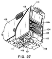
- Fig. 27 is a perspective view showing a conventional ink jet cartridge.
- Fig. 28 is a perspective view showing the exploded state of the ink jet cartridge shown in Fig. 27.
- a head cartridge 110 is constituted of an ink jet head 101 provided with an ink discharge port 103 for discharging liquids such as an ink, a head holder 102 as a head holding member with the ink jet head 101 attached thereto, a flexible cable 104 bonded to the ink jet head 101 and attached to the head holder 102, and a tank holder 109 as a tank holding member, detachably attached to the head holder 102, for mounting thereon an ink tank.
- the ink jet head 101 includes: an element substrate provided with a heat converting element, a piezo element and other energy generating elements for generating an energy utilized to discharge the ink from the ink discharge port 103; and a grooved top plate provided with a groove part constituting an ink flow path, a wall part forming an ink flow path wall, and a hollow part forming a common liquid chamber for supplying the ink to the ink flow path, and the ink flow path and common liquid chamber are formed by bonding the element substrate to the grooved top plate.
- the grooved top plate is integrally formed with an orifice plate provided with a plurality of discharge ports which communicate with the ink flow path.
- one end of the flexible cable 104 is bonded to the ink jet head 101, and the bonded part of the flexible cable 104 and ink jet head 101 is disposed inside the head holder 102.
- One surface of the other end of the flexible cable 104 is provided with a plurality of contact pads 105 electrically connected to contact pads which are disposed on an ink jet apparatus main body.
- the contact pad 105 contacts the main body side contact part (not shown) of the ink jet apparatus, so that a signal for discharging the ink via the ink discharge port 103 can be transmitted to the ink jet head 101 through the contact pad 105.
- an opening 108 for passing the flexible cable 104 is formed in the surface of the head holder 102 other than the surface on which the ink jet head 101 is disposed.
- the part of the flexible cable 104 provided with a plurality of contact pads 105 is drawn to the outside of the head holder 102 from the inside of the head holder 102 through the opening 108, and the part of the flexible cable 104 provided with a plurality of contact pads 105 forms an exposed part 104a exposed to the outside of the head holder 102.
- the ink jet head is fixed by the engagement part molded in the head holding member, but in this constitution, the positioning of the head depends on the precision of the engagement part, and the mold processing precision must be set to be very high.
- the head positioning is performed using the molded surface as a reference, but a strain is sometimes generated in the molded surface of a molded material.
- the strain is large, the desired attachment direction of the head is not obtained, a deviation is generated in a discharge direction, and it cannot necessarily be said that the productivity is high.
- the deviation of the head attachment direction in each ink jet cartridge causes a deviation in a jet position. Therefore, the attachment direction of the head to the ink jet cartridge needs to be set with a higher precision, and the simple constitution of the ink jet cartridge has been demanded in which the head attachment direction can be arranged with the high precision.
- an object of the present invention is to provide an ink jet cartridge with an ink jet head attached thereto, in which the ink jet head is easily positioned with a high precision and high-quality recording is possible, and further to provide an ink jet apparatus with the ink jet cartridge used therein in a simple constitution and at a low cost.
- an ink jet cartridge comprising: an ink jet head including a plurality of arranged discharge ports for discharging ink, an element substrate provided with a plurality of energy generating elements for generating an energy to discharge the ink, and a base plate for supporting the element substrate; an ink tank holding member for holding an ink tank for containing the ink; and a head holding member for connecting the ink tank holding member to the ink jet head.
- an ink jet head including a plurality of arranged discharge ports for discharging ink, an element substrate provided with a plurality of energy generating elements for generating an energy to discharge the ink, and a base plate for supporting the element substrate; an ink tank holding member for holding an ink tank for containing the ink; and a head holding member for connecting the ink tank holding member to the ink jet head.
- the base plate is preferably inclined with respect to the head holding direction.
- the ink tank holding member includes an ink supply tube for introducing the ink to the ink jet head
- the ink jet head includes an ink flow inlet port for introducing the ink into the ink jet head from the ink tank
- an elastic member is disposed between the ink flow inlet port and the ink supply tube, and the head is elastically supported by the elastic force of the elastic member in a state where the head is sandwiched by the ink tank holding member and head holding member.
- the ink jet head is preferably fixed to the ink jet cartridge using a force by a rotation moment.
- an ink jet apparatus comprising: the above-described ink jet cartridge; and record material conveyance means for conveying a record material which receives the liquid discharged from the ink jet head.
- the ink jet cartridge is mounted on the ink jet apparatus in an attachable/detachable state.
- an ink jet apparatus comprising: the above-described ink jet cartridge; and recovery means for recovering the ink jet head of the ink jet cartridge.
- the ink jet cartridge is mounted on the ink jet apparatus in the attachable/detachable state.
- the recovery means comprises suction recovery means, or a wiper blade for wiping the surface of the ink jet head provided with a discharge port.
- a wiper cleaner for cleaning the wiper blade is preferably disposed between the head holding member and the ink jet head.
- a step is further preferably disposed on the ink jet head side of the wiper cleaner.
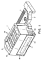
- the ink jet head (hereinafter referred to simply as the head) is a unit integrally formed by assembling a plurality of components.
- An element substrate 3 (see Figs. 2 and 3) is bonded onto a base plate 2, and a grooved top plate 4 is bonded onto the substrate, and is then pressed by a pressing member 5.
- an ink supply unit 6 for supplying ink to the grooved top plate 4 is further disposed on the pressing member, and fixed to the base plate 2.
- the rear part of the base plate 2 is bonded to a wiring board 7 which is connected to a flexible cable 61 (see Fig. 4).
- Fig. 2 shows that the ink supply unit is removed from Fig. 1
- Fig. 3 is a sectional view of the head 1 of Fig. 1.
- One surface (the lower surface in Fig. 2) of the element substrate 3 is bonded to the base plate 2, and the other surface (the upper surface in Fig. 2) is provided with a plurality of energy generating elements 62 (see Fig. 3).
- the energy generating element 62 of the present embodiment is a heating element.
- the grooved top plate 4 is provided with a groove to form an ink flow path 8 and a hollow to form a common liquid chamber 9 for communicating with the groove in a positional relation such that a plurality of energy generating elements 62 on the element substrate 3 can be connected (see Fig. 3).
- an orifice plate 10 is integrally formed on the grooved top plate 4, and is provided with a plurality of fine discharge ports (orifices) 11 which communicate with the ink flow path 8.
- center axis of the discharge port 11 is inclined by about ten degrees with respect to the flow direction of the ink flow path 8.
- the base plate 2, element substrate 3 and ink flow path 8 are all disposed substantially parallel to one another.
- the orifice plate 10 when the entire surface of the orifice plate 10 is inclined by about 80 degrees with respect to the entire surface of the base plate 2 and element substrate 3, the orifice plate is positioned to be substantially vertical to the center axis of the discharge port 11.
- the surface of the base plate 2 opposite to the back surface of the orifice plate 10 is provided with an inclined part 12 which forms substantially the same inclination angle as that of the orifice plate 10.
- a silicon layer 13 for protecting the orifice plate 10 can be disposed in a gap between the element substrate 3 and base plate 2 and the orifice plate 10.
- the silicon layer 13 is formed by injecting a silicon agent toward the back surface of the orifice plate 10 from silicon agent injection ports (not shown) disposed in opposite side parts of the grooved top plate 4, and then solidifying the agent.
- the base plate 2 is fixed to the element substrate 3 by a thermally conductive adhesive in a positional relation such that the gap between the orifice plate 10 and the inclined part 12 of the base plate 2 is about 0.1 mm.
- the ink supply unit 6 is provided with an ink flow inlet tube 16 to form an ink flow inlet path 15 which communicates with the common liquid chamber 9.
- the ink flow inlet tube 16 of the ink supply unit 6 is L-shaped.
- the ink flow inlet tube 16 is connected to the grooved top plate 4 by filling the periphery of the ink flow inlet 16 pressed onto the grooved top plate 4 with the silicon agent and solidifying the agent (not shown).
- an elastic material is used in the ink flow inlet tube 16.
- the ink supply unit 6 is provided with an enclosure part 18 to surround the periphery of the orifice plate 10, and this enclosure part 18 protects the orifice plate 10 from a friction force by a wiper for cleaning the surface of a recording device (not shown), an external force from a side surface, and the like.
- the enclosure part 18 is substantially parallel to the orifice plate 10, and inclined by about 80 degrees with respect to the element substrate 3.
- the enclosure part 18 becomes parallel to a record sheet 63, and the interval between both can be reduced.
- One surface of the ink supply unit 6 (the top surface of Fig. 1) is substantially vertical to the orifice plate 10 and a record sheet surface, and inclined by about ten degrees with respect to the base plate 2, element substrate 3, and ink flow path 8.
- the top surface of the ink supply unit 6 is provided with an edge 19 for scraping off a thickened ink adhering to the wiper.
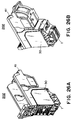
- the head 1 constituted as described above is held between a head holding member 30 and an ink tank holding member 41 as shown in Figs. 4, 26A, 26B and is thereby attached to an ink jet cartridge.
- an ink supply tube 43 of the ink tank holding member 41 is pressed onto an ink flow inlet port flat part 17 of the head 1 via an elastic member 50 (see Fig. 10). Furthermore, the head 1 is elastically supported by the head holding member 30 and ink tank holding member 41 by the force applied from a vertical direction via the elastic member 50 by an ink supply tube 43 and a bond pressing pillar 44 protruded from the ink tank holding member 41 with respect to the ink flow inlet flat part 17 in which an ink flow inlet port 20 of the ink supply unit 6 is positioned.
- the ink is supplied to the discharge ports 11 from an ink tank 40 successively via the ink supply tube 43, a communication hole 51 of the elastic member 50, the ink flow inlet port 20, the ink flow inlet tube 16, the common liquid chamber 9, and the ink flow path 8, the energy generating element 62 is driven, and the ink is then discharged toward the record sheet 63 outside from the discharge ports 11.
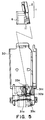
- a head insertion space for inserting the base plate 2 is disposed inside the head holding member 30, head insertion guides 31a and 31c, 31b and 31d are disposed on both sides of the space, and head support parts 32a, 32b are disposed in the bottom part of the head insertion space to determine the protruding amount of the head 1 from the head holding member 30.
- the head insertion space is inclined with respect to the insertion direction of the ink tank holding member into the head holding member 30.
- the base plate 2 When the base plate 2 is guided and inserted into the space, the base plate 2 abuts on the head support part 32a, 32b and its movement in the insertion direction of the base plate 2 is regulated.
- the head When the head is further pressed by the pressing force of the elastic member 50, the head starts its rotating movement using the head support parts 32a, 32b as support points.
- the ends of the head insertion guides 31a, 31b are provided with head receiving parts 33a, 33b which also determine the rotation position of the head.
- the head holding member 30 is provided with a head receiving part 33c in substantially symmetric positions of the back surface of the base plate centering on a rotation axis with respect to the head receiving parts 33a, 33b, so that a rotation moment is efficiently utilized.
- these head receiving parts 33a, 33b and head receiving part 33c are disposed on the surface and back surface of the base plate so that the positions from the surface direction of the base plate 2 are in a relation to form a substantial isosceles triangle, and the pressure can be dispersed as uniformly as possible.
- the head support parts 32a, 32b, and head receiving parts 33a, 33b, 33c have an R-shaped section in order to minimize a contact area with respect to the base plate 2.
- the base plate 2 is supported by a point in the constitution.
- the surface by which the base plate is supported is univocally defined by the three-point support of the head.
- the head holding member 30 receives the pressing force from the elastic member 50 by the head support parts 32a, 32b, and head receiving parts 33a, 33b, 33c, and the head 1 is elastically supported in a positional relation in which the surface of the orifice plate 10 is kept to be parallel to the surface of the record sheet 63.
- an arrow F indicates the pressing force of the elastic member.
- the head 1 Upon receiving the pressing force F, the head 1 performs its rotating movement in a counterclockwise direction, the rotating movement is regulated by the head receiving parts 33a, 33b, 33c, and forces shown by arrows F1, F2 are generated in a direction intersecting the arrow F to fix the head 1.
- the base plate 2 Since the base plate 2 is inclined in this manner, the regulation in the intersecting direction can simultaneously be performed by the force of the elastic pressing direction (the force of the arrow F).
- the head 1 In the constitution of the present invention in which the head 1 is self-aligned by the elastic force in this manner, the head 1 can highly precisely and easily be positioned as long as only the precision of the head support part and head receiving parts 33a, 33b, 33c is high.
- the cap abutment force can finely be adjusted.
- the angle of the surface of the orifice plate 10 is regulated by the head receiving parts 33a, 33b, 33c and is unchanged, the abutment force of the cap 203a (see Fig. 18) is prevented from being non-uniform.
- head side receiving parts 39a, 39b are disposed, and one head side receiving part 39b is formed as a leaf spring.
- the sections of the head side receiving parts 39a, 39b are also R-shaped similarly as the head support parts 32a, 32b and head receiving parts 33a, 33b, 33c.
- the head holding member 30 is also provided with a wiper cleaner insertion guide for inserting a wiper cleaner 21 formed of a hydrophilic porous plastic material described later (see Figs. 4, 6).
- a wiper cleaner insertion guide for inserting a wiper cleaner 21 formed of a hydrophilic porous plastic material described later (see Figs. 4, 6).
- the inner surface of the head holding member 30 is provided with an engagement pin 36 and engagement hole 37 disposed also to position and fix the head holding member 30 to the ink tank holding member 41, and a cylindrical part 35 into which a fixing screw 34 (not shown) for fixing the head holding member 30 to the ink tank holding member 41 can be inserted.
- This ink tank 40 is attached to the ink tank holding member 41 which is fixed to the head holding member 30.
- the ink tank 40 is detachable/attachable with respect to the ink tank holding member 41 by the operation of a lever 42.
- the ink tank holding member 41 is provided with an outer shape which can be mounted inside the head holding member 30.
- disposed on the bottom surface of the ink tank holding member 41 are one ink supply tube 43 communicating with the ink tank 40 so that the ink can be discharged, two bond pressing pillars 44 arranged in series with the ink supply tube 43, a cylindrical part 46 provided with a screw hole 45 into which the screw 34 (not shown) is inserted, an engagement part 47 and engagement recess 48 necessary for the bonding to the engagement pin 36 and engagement hole 37 of the head holding member 30, support parts 49a, 49c for supporting the head holding member 30, leaf springs 42a, 42b for supporting the base plate 2, a wiper cleaner fixing pin 22 for fixing the wiper cleaner 21, and the like.
- a tank pin engagement hole 23 for engaging with a tank pin (not shown) disposed on the bottom of the ink tank 40 is disposed on the bottom surface on the ink tank attachment side of the ink tank holding member 41.
- the tank pin engagement hole 23 has a substantially square shape and is provided with a protrusion 23a protruded from the head attachment side, and the position precision during the engagement of the tank pin is enhanced by this protrusion.
- the engagement part 47 and engagement recess 48 are disposed opposite to the engagement hole 37 and engagement pin 36 of the head holding member 30, respectively, and the bottom surface is positioned by the engagement of these components during the inserting of the ink tank holding member.
- the ink supply tube 43 is thus guided and positioned opposite to the ink flow inlet tube 16 of the head 1.
- the cylindrical part 46 abuts on the cylindrical part 35 of the head holding member 30 to form a continuous cylindrical shape.
- welding or lock mechanism may be used instead of the screw 34, or the screw 34 can be fixed with an adhesive or a silicone agent, but by using only the screw 34 to fix the members as in the present embodiment, there are advantages that the attachment/detachment is facilitated, the reuse of components, the development of a separate unit, and other uses are facilitated, the structure is simplified and that the cost can be reduced.
- cylindrical part 46 as the fixing part of the head holding member to the ink tank is disposed in the area surrounded with the support parts 49a, 49b, 49c, and the forces applied to the respective support parts can be dispersed as uniformly as possible.
- two bond pressing pillars 44 have substantially the same height as that of the ink supply tube 43, and the ink supply tube 43 and bond pressing pillars 44 are disposed outside the area (triangular area) surrounded with the support parts 49a, 49b, 49c.
- leaf springs 42a, 42b are disposed so that the force is equally applied to the base plate 2.
- the leaf springs 42a, 42b apply a constant force to the base plate 2 to support the head 1.
- the wiper cleaner fixing pin 22 is shaped to abut on the wiper cleaner 21.
- Figs. 12B and 12C are enlarged views of the elastic member 50.
- the elastic member 50 is disposed on the part of the ink supply tube 43 and bond pressing pillars 44, and the communication hole 51 is disposed in the part held between the ink supply tube 43 and the ink flow inlet port 20.
- the bond pressing pillar 44 with a tubular shape similar to that of the ink supply tube 43 may be formed by molding the pillar simultaneously with the ink supply tube 43.
- this bond pressing pillar 44 is a so-called dummy ink supply tube.
- a thickness t1 of the part opposite to the bond pressing pillar 44 is larger than a thickness t2 of the part opposite to the ink supply tube 43.
- the ink tank holding member 41 is provided with carriage guides 24a, 24b which function as guides during the mounting of the ink jet cartridge on a carriage.
- the carriage guides 24a, 24b of the present embodiment have a groove shape, and engage with protrusions (not shown) on the top end of a partition plate disposed among the mount parts of the respective cartridges of the carriage.
- the movement of the ink jet cartridge is regulated so that the discharge port surface of the ink jet cartridge is prevented from inadvertently contacting the electric connection part (not shown) of the carriage.
- the discharge port surface of the ink jet cartridge fails to contact the electric connection part of the carriage, and a wide window shape is formed, so that the rotating operation of the ink jet cartridge can smoothly be performed during the final positioning with respect to the carriage.
- the carriage guides 24a, 24b are disposed on the thick part of the wall surface constituting the ink tank holding member, which is apart from the part to be attached to the head unit holding member, so that the ink tank can securely be held without deteriorating the rigidity of the ink tank holding member itself.
- the carriage guides 24a, 24b may be extended either on the bottom surface side of the side surface part or the end of the side opposite to the bottom surface, but in the present embodiment, in order to secure the rigidity of the ink tank holding member itself, the area on the bottom surface side of the carriage guide 24b is formed in a recess not passed through the wall surface. Moreover, the top end on the side of the carriage guide 24a is not cut out and a frame is left.
- this shape strictly regulates the position of the ink jet cartridge with respect to the carriage scanning direction. Moreover, the frame of the top end in the present embodiment fails to contact the protrusion disposed on the carriage during the rotating operation.
- partition plates 211 are formed substantially parallel to the side surface of an ink jet cartridge 202, and at predetermined intervals with respect to the ink jet cartridge 202, and constitute two surfaces in a space into which the ink jet cartridge 202 is inserted/fixed.
- the partition plate 211 between the adjacent ink jet cartridges is shared by the respective ink jet cartridges 202.
- a protrusion 211a provided with a substantially rectangular shape protruded on the ink jet cartridge side (inner side) is formed on a corner on the ink jet cartridge insertion side of the partition plate 211.
- the protruding amount of the carriage protrusion 211a is set to be smaller than the width of a carriage guide narrow part 24b of the ink jet cartridge (see Fig. 25), the insertion of the ink jet cartridge into the carriage 201 is impossible in a position other than a position in which the carriage protrusion 211a meets the carriage guide narrow part 24b of the ink jet cartridge.
- the position of the carriage protrusion 211a agrees with that of the carriage guide narrow part 24b of the ink jet cartridge, the insertion of the ink jet cartridge into the carriage becomes possible.
- the cartridge is inserted downward in the drawing along the carriage guide narrow part 24b in the position where the carriage guide narrow part 24b of the ink jet cartridge meets the protrusion 211a of the carriage 201.
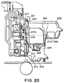
- the movement of the ink jet cartridge 202 in the rotation direction is regulated (see Fig. 20).
- the ink jet cartridge 202 When the ink jet cartridge 202 is further inserted, the lower part of an X' positioning part 221 of the ink jet cartridge is guided by the inclined part of a head hook 213, and the ink jet cartridge 202 is inclined in a direction apart from a contact part 212 (see Fig. 21).
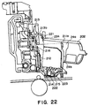
- the carriage protrusion 211a is drawn into the carriage guide wide part 24a opened wide upward from the carriage guide narrow part 24b of the ink jet cartridge, the ink jet cartridge 202 is further inclined, an XZ positioning part 222 of the ink jet cartridge is guided by a carriage XZ positioning part 214, the leaf spring for urging the ink jet cartridge 202 allows a Y positioning part 223 of the ink jet cartridge to abut on a Y positioning part 215, and the cartridge is inserted into the bottom of the carriage 201 (see Fig. 22).
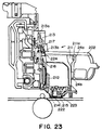
- the tip end of a head hook receiving part 221a of the ink jet cartridge rotates the head hook 213, the tip end of the head hook receiving part 221a goes beyond the tip end of the head hook 213, then the ink jet cartridge 202 is drawn in by an extension spring 216, the X' positioning part 221 of the ink jet cartridge abuts on a carriage X' positioning part 217, the state of Fig. 24 is obtained, and the fixing of the ink jet cartridge 202 is completed.
- the window depth of the carriage guide wide part 24a of the ink jet cartridge is set to be a size such that the carriage protrusion 211a is not interfered with.
- the carriage guide narrow part 24b of the ink jet cartridge has a boundary between the window part and the recess part, but the carriage protrusion 211a is tapered toward the partition plate 211 from its top, and the ink jet cartridge 202 can therefore be extracted without being caught by the protrusion 211a.
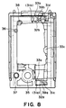
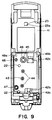
- the head holding member 30 is provided with a cutout part 26 for use in drawing the flexible cable 61 to the outside from the inside of the head holding member 30.
- This cutout part 26 is cut in the ink tank holding member insertion direction of the head holding member 30.
- a guide rib 54 extended in the ink tank holding member insertion direction is disposed opposite to the cutout part 26 of the ink tank holding member 41.
- This guide rib 54 is guided by a taper part 29, and guides the side surface of the abutment part 26 during the inserting operation.
- the flexible cable 61 is bonded to the outer surface of the head holding member 30 (the surface forming a contact part) by a hot-melt seat.
- a groove is made in the periphery of the hot-melt seat placing surface of the head holding member 30, and this groove prevents the molten resin of the hot-melt seat from overflowing during the bonding.
- Numerals 27a, 27b of Figs. 11, 13 denote through ports for passing the flexible cable 61 and head holding member 30. When a jig is protruded from the through ports 27a, 27b, the flexible cable 61 is positioned with respect to the head holding member 30 and the flexible cable 61 can be bonded to a desired position.
- the through ports 27a, 27b receive a pin disposed on the contact part on the carriage side during the mounting of the ink jet cartridge on the ink jet apparatus carriage, the positioning of the electric connection can be secured.
- the through port 27b is formed in an elongated hole shape in consideration of the tolerance of the pin and through ports 27a, 27b.
- the orifice plate 10 is parallel to the surface of the record sheet 63, and the row of the discharge ports 11 is inclined by about 3.58 degrees with respect to the feeding direction of the record sheet 63 as shown in Fig. 15.
- the drive timing of the energy generating element can be shifted, and the above-described problems can be avoided even when the ink is discharged from all the discharge ports 11.
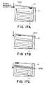
- a wiper cleaner will next be described in detail with reference to Figs. 16A to 16E and Figs. 17A to 17C.
- the ink jet apparatus for discharging the ink from the discharge port to form an image
- the periphery of the discharge port is gradually contaminated with the ink, dust, paper powder, and the like.
- the ink jet apparatus is provided with a recovery part including a wiper blade for periodically wiping the ink from the periphery of the discharge port.
- a wiper blade for periodically wiping the ink from the periphery of the discharge port.
- the wiper cleaner 21 is disposed on the ink jet cartridge to absorb the ink of a wiper blade 203b (see Fig. 18), and the wiper blade 203b is constantly kept in a clean state. Moreover, since the wiper cleaner 21 is formed of a hydrophilic porous plastic material, the ink is diffused in the entire wiper cleaner 21 by a capillary force. As a result, there is no excess ink on the contact surface with the wiper blade 203b, and the ink adhering to the wiper blade can always be absorbed by the wiper cleaner.
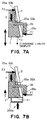
- the wiper blade 203b is advanced parallel to the discharge port row and vertically to the surface, and the advancement direction starts from the base plate side. Specifically, the wiping operation is performed while the wiper cleaner 21 is on the downstream side of the wiping direction (arrow direction).
- the wiper blade having wiped off the ink on the surface once returns to its original state at a step 21a of the wiper cleaner 21, and ink 70 is scraped with the edge of the wiper cleaner 21.
- the scraped ink 70 is held by the recess part of the step 21a and absorbed by the wiper cleaner. Since the surface area of the wiper cleaner 21 in contact with the ink is enlarged particularly by the step shape, the ink can quickly be absorbed.
- the wiper blade 203b to perform more effective cleaning.
- the ink jet cartridges are mounted on the carriage in order from yellow (Y), magenta (M), cyan (C), and black (Bk).
- Y yellow
- M magenta
- C cyan
- Bk black
- the wiper cleaner 21 of the present invention wipes the cartridge not only from the base plate side but also from the upstream direction of the wiping direction of the wiper cleaner 21.
- the wiper blade 203b and wiper cleaner 21 enter with an angle, and the ink 70 adhering to the wiper blade 203b gradually moves to the left side from the right side of the drawing. Moreover, since the ink 70 is simultaneously absorbed by the wiper cleaner 21 during the movement, more effective ink absorption can be performed. Furthermore, since the wiper cleaner 21 is formed in a stepped shape, the cleaner has an ink scraping effect similar to that of the edge of the ink supply unit 6. The wiper blade of the present invention constantly performs the optimum cleaning regardless of the wiping direction in this manner. Furthermore, for the stepped shape of the wiper cleaner, the number of edges is increased, additionally the components can be shared with the discharge port protective cap of the ink jet cartridge provided beforehand with no wiper cleaner product, and the cost can be reduced.
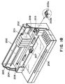
- Fig. 18 is a schematic view showing the constitution of one embodiment of an ink jet apparatus 200 on which the ink jet cartridge of the present embodiment is mounted.
- a plurality of ink jet cartridges 202a to 202d are mounted on the carriage 201 held by a guide axis 205 and lead screw 204, and image recording is performed on a record sheet 206 by moving the carriage 201 in a left-to-right direction.
- the guide axis 205 is a fixed axis which plays a role of guiding the carriage 201 in the left-to-right direction during the movement.
- the lead screw 204 is a rotation axis with a spiral groove (not shown) formed thereon, and the carriage 201 can be moved in the left-to-right direction by rotating the lead screw forward and backward.
- the record sheets 206 are stored in the lower part of the ink jet apparatus 200, and fed to the printing part of the ink jet apparatus 200 from below a press plate 209 by a feed roller 207.
- a discharge roller 208 feeds only the necessary printed area of the record sheet 206 and discharges the sheet from the ink jet apparatus 200.
- the recovering operation of the ink jet cartridge 202 is performed in a recovery unit 203 not to deteriorate the image recording quality.
- This recovery unit 203 is provided with the cap 203a which abuts on the surface of the head provided with the discharge ports and which can perform suction recovery, and the wiper blade 203b for wiping and cleaning the surface of the head provided with the discharge ports.
- the ink jet cartridge in which the high precision positioning of the ink jet head can easily be performed with respect to the ink jet cartridge and the high quality recording is possible, and the ink jet apparatus using this cartridge can be realized with the simple constitution and at the low cost.
- an ink jet cartridge comprising: an ink jet head including a plurality of arranged discharge ports for discharging ink, an element substrate provided with a plurality of energy generating elements for generating an energy to discharge the ink, and a base plate for supporting the element substrate; an ink tank holding member for holding an ink tank for containing the ink; and a head holding member for connecting the ink tank holding member to the ink jet head, and by holding the ink jet head by the ink tank holding member and the head holding member, the ink jet head is elastically supported in a head sandwiching direction, so that the positioning of the ink jet head can easily be performed with respect to the ink jet cartridge with a high precision, the high quality recording is possible, and the ink jet apparatus using this cartridge can be realized with a simple constitution and at a low cost.
Landscapes
- Ink Jet (AREA)
Abstract
Description
Claims (56)
- An ink jet cartridge comprising:an ink jet head including a plurality of arranged discharge ports for discharging ink, an element substrate provided with a plurality of energy generating elements for generating an energy to discharge the ink, and a base plate for supporting the element substrate;an ink tank holding member for holding an ink tank for containing the ink; anda head holding member for connecting the ink tank holding member to said ink jet head,
wherein by sandwiching said ink jet head by said ink tank holding member and said head holding member, said ink jet head is elastically supported in a head sandwiching direction. - The ink jet cartridge according to claim 1 wherein said base plate is inclined with respect to said head sandwiching direction.
- The ink jet cartridge according to claim 1 wherein said ink tank holding member comprises an ink supply tube for introducing the ink to said ink jet head, said ink jet head comprises an ink flow inlet port for introducing the ink into said ink jet head from said ink tank, an elastic member is disposed between the ink flow inlet port and said ink supply tube, and the head is elastically supported by the elastic force of the elastic member in a state where said head is sandwiched by the ink tank holding member and the head holding member.
- The ink jet cartridge according to claim 2 wherein said ink jet head is fixed to said ink jet cartridge using a force by a rotation moment.
- The ink jet cartridge according to claim 4 wherein said ink jet head is fixed to said ink jet cartridge by the force by the rotation moment in which a support part is used as a support point or an axis.
- The ink jet cartridge according to claim 1 wherein said head holding member comprises a support part for supporting the head with respect to the elastic pressing direction of said elastic member, and a head receiving part for regulating the movement of the base plate in a direction intersecting said head sandwiching direction and in a base plate inclination direction.
- The ink jet cartridge according to claim 6 wherein said head receiving part is disposed in three places.
- The ink jet cartridge according to claim 7 wherein said three head receiving parts are formed in positions forming an isosceles triangle with respect to the base plate.
- The ink jet cartridge according to claim 6 wherein the support part of said base plate and the head receiving part have an R-shaped section.
- The ink jet cartridge according to claim 1 wherein said ink tank holding member comprises a base plate abutment part, and the base plate abutment part has a leaf spring structure.
- The ink jet cartridge according to claim 1 wherein said head holding member comprises a head side receiving part in a direction of arranging said plurality of discharge ports.
- The ink jet cartridge according to claim 11 wherein said head side receiving part is disposed on the opposite sides of the base plate, and one head side receiving part has a leaf spring structure.
- The ink jet cartridge according to claim 11 wherein said head side receiving part has an R-shaped section.
- The ink jet cartridge according to claim 3 wherein said ink supply tube of said ink tank holding member has bond pressing pillars with the same height as that of said ink supply tube at opposite sides thereof, and said elastic member is extended to the part of the bond pressing pillars including the ink supply tube.
- The ink jet cartridge according to claim 14 wherein said elastic member has a part corresponding to said bond pressing pillar thicker than a part corresponding to said ink supply tube.
- The ink jet cartridge according to claim 14 wherein the fixing of said head holding member to said ink tank holding member on the attachment side of said ink jet head is performed by three support parts and a connection part disposed in an area surrounded with three support parts.
- The ink jet cartridge according to claim 16 wherein said ink supply tube and the bond pressing pillar are disposed outside the area surrounded with said three support parts.
- The ink jet cartridge according to claim 1 wherein said head holding member is provided with a contact part to which a flexible cable, bonded to said ink jet head, for transmitting an electric signal to discharge a liquid from said ink jet head is attached, and a cutout part, cut in a direction of inserting said ink tank holding member, for passing said flexible cable, and the part of said flexible cable provided with said contact part is exposed to the outside of said ink tank holding member from said cutout part of said head holding member.
- The ink jet cartridge according to claim 18 wherein said ink tank holding member is provided with a guide which is extended in the insertion direction in a position corresponding to said cutout part.
- The ink jet cartridge according to claim 18 wherein said cutout part is disposed on one side of said head holding member.
- The ink jet cartridge according to claim 19 wherein a protrusion for enlarging the width of said cutout part by said guide is disposed on the tip end of said head holding member on the end of the cutout part.
- The ink jet cartridge according to claim 21 wherein said ink tank holding member comprises a recess part for engaging with said protrusion, and said cutout part becomes a slit by the engagement.
- The ink jet cartridge according to claim 18 wherein said flexible cable is fixed to said head holding member by a hot-melt seat.
- The ink jet cartridge according to claim 23 wherein said head holding member is provided with a groove in the periphery of a fixing part by said hot-melt seat.
- The ink jet cartridge according to claim 18 wherein said flexible cable includes at least one bent part adapted for the inner shape of said head holding member.
- The ink jet cartridge according to one of claims 18 to 25 wherein said flexible cable and head holding member are provided with a plurality of through ports which engage with positioning protrusions disposed on an electric contact part on a device side.
- The ink jet cartridge according to claim 26 wherein at least one of said plurality of through ports has an elongated hole shape.
- The ink jet cartridge according to claim 1 wherein a wiper cleaner for cleaning a wiper blade, disposed on an ink jet apparatus, for wiping the surface of said ink jet head provided with the discharge port is disposed between said head holding member and the ink jet head.
- The ink jet cartridge according to claim 28 wherein a step is disposed on the ink jet head side of said wiper cleaner.
- An ink jet apparatus comprising: the ink jet cartridge according to any one of claims 1 to 25, 27 and 29; and record material conveyance means for conveying a record material for receiving a liquid discharged from said ink jet head of the ink jet cartridge, wherein said ink jet cartridge is mounted in an attachable/detachable state.
- An ink jet apparatus comprising: the ink jet cartridge according to claim 26; and record material conveyance means for conveying a record material for receiving a liquid discharged from said ink jet head of the ink jet cartridge, wherein said ink jet cartridge is mounted in an attachable/detachable state.
- An ink jet apparatus comprising: the ink jet cartridge according to any one of claims 1 to 25 and 27; and recovery means for performing a recovery treatment of said ink jet head of the ink jet cartridge, wherein said ink jet cartridge is mounted in an attachable/detachable state.
- An ink jet apparatus comprising: the ink jet cartridge according to claim 26; and recovery means for performing a recovery treatment of said ink jet head of the ink jet cartridge, wherein said ink jet cartridge is mounted in an attachable/detachable state.
- The ink jet apparatus according to claim 32 wherein said recovery means comprises suction recovery means.
- The ink jet apparatus according to claim 33 wherein said recovery means comprises suction recovery means.
- The ink jet apparatus according to claim 32 wherein said recovery means comprises a wiper blade for wiping the surface of said ink jet head provided with a discharge port.
- The ink jet apparatus according to claim 33 wherein said recovery means comprises a wiper blade for wiping the surface of said ink jet head provided with a discharge port.
- The ink jet apparatus according to claim 36 wherein said ink jet cartridge comprises a wiper cleaner for cleaning said wiper blade between said head holding member and the ink jet head.
- The ink jet apparatus according to claim 37 wherein said ink jet cartridge comprises a wiper cleaner for cleaning said wiper blade between said head holding member and the ink jet head.
- The ink jet apparatus according to claim 38 wherein a step is disposed on the ink jet head side of said wiper cleaner.
- The ink jet apparatus according to claim 39 wherein a step is disposed on the ink jet head side of said wiper cleaner.
- The ink jet apparatus according to claim 38 wherein a plurality of ink jet cartridges are arranged, the cleaning of the ink jet heads of the plurality of ink jet cartridges is continuously performed by relatively moving a single wiper blade along a head arrangement direction, and said wiper cleaner is disposed on the downstream side of a head wiping direction.
- The ink jet apparatus according to claim 39 wherein a plurality of ink jet cartridges are arranged, the cleaning of the ink jet heads of the plurality of ink jet cartridges is continuously performed by relatively moving a single wiper blade along a head arrangement direction, and said wiper cleaner is disposed on the downstream side of a head wiping direction.
- The ink jet apparatus according to claim 38 wherein the angle of the edge of said wiper cleaner on the upstream side of the wiping direction is different from the angle of the wiper blade.
- The ink jet apparatus according to claim 39 wherein the angle of the edge of said wiper cleaner on the upstream side of the wiping direction is different from the angle of the wiper blade.
- An ink jet cartridge comprising:an ink jet head comprising a plurality of arranged discharge ports for discharging ink, and an element substrate provided with a plurality of energy generating elements for generating an energy to discharge the ink;an ink tank holding member for holding an ink tank for containing the ink; anda head holding member for connecting the ink tank holding member to said ink jet head,
wherein said ink jet head is sandwiched by said ink tank holding member and said head holding member. - An ink jet cartridge comprising:an ink jet head comprising a plurality of arranged discharge ports for discharging ink, and an element substrate provided with a plurality of energy generating elements for generating an energy to discharge the ink;an ink tank holding member for holding an ink tank for containing the ink; anda head holding member for connecting the ink tank holding member to said ink jet head,
wherein said ink jet head is movably supported between said ink tank holding member and said head holding member. - An ink jet cartridge comprising:an ink jet head comprising a plurality of arranged discharge ports for discharging ink, and an element substrate provided with a plurality of energy generating elements for generating an energy to discharge the ink;an ink tank holding member for holding an ink tank for containing the ink; anda head holding member for connecting the ink tank holding member to said ink jet head,
wherein said ink jet head is sandwiched and mounted between said ink tank holding member and said head holding member, and the fixing of said head holding member to said ink tank holding member on the ink jet head mounting side is performed by three support parts and a connection part disposed in an area surrounded with the three support parts. - An ink jet cartridge comprising:an ink jet head comprising a plurality of arranged discharge ports for discharging ink, an element substrate provided with a plurality of energy generating elements for generating an energy to discharge the ink, and a base plate for supporting the element substrate;an ink tank holding member for holding an ink tank for containing the ink; anda head holding member for connecting the ink tank holding member to said ink jet head,
wherein said ink jet head is sandwiched and mounted between said ink tank holding member and said head holding member, and said ink tank holding member is provided with a support member for elastically supporting said base plate of the ink jet head sandwiched between said ink tank holding member and said head holding member. - An ink jet cartridge comprising:an ink jet head comprising a plurality of arranged discharge ports for discharging ink, and an element substrate provided with a plurality of energy generating elements for generating an energy to discharge the ink;an ink tank holding member for holding an ink tank for containing the ink; anda head holding member for connecting the ink tank holding member to said ink jet head,
wherein a wiper cleaner for cleaning a wiper blade is disposed on the place of said head holding member adjacent to said ink jet head in an area corresponding to said wiper blade for wiping off the discharge port surface of said ink jet head. - An ink jet cartridge attachably/detachably mounted on an ink jet apparatus, comprising:an ink jet head comprising a plurality of arranged discharge ports for discharging ink, and an element substrate provided with a plurality of energy generating elements for generating an energy to discharge the ink;an ink tank holding member for holding an ink tank for containing the ink; anda head holding member for connecting the ink tank holding member to said ink jet head,
wherein a guide groove is disposed for the mounting on said ink jet apparatus. - An ink jet apparatus on which an ink jet cartridge comprising an ink jet head including a plurality of arranged discharge ports for discharging ink and an element substrate provided with a plurality of energy generating elements for generating an energy to discharge the ink, an ink tank holding member for holding an ink tank for containing the ink, and a head holding member for connecting the ink tank holding member to said ink jet head is attachably/detachably mounted,
wherein a carriage on which a plurality of said ink jet cartridges are attachably/detachably mounted is disposed, the carriage is provided with partition plates for partitioning said plurality of ink jet cartridges, and the partition plate is provided with a protrusion for engaging with a part of a housing of said ink jet cartridge in order to mount/guide said ink jet cartridge to said carriage. - A method of manufacturing an ink jet cartridge comprising: an ink jet head including a plurality of arranged discharge ports for discharging ink and an element substrate provided with a plurality of energy generating elements for generating an energy to discharge the ink, an ink tank holding member for holding an ink tank for containing the ink, and a head holding member for connecting the ink tank holding member to said ink jet head,said ink jet cartridge manufacturing method comprising the steps of: assembling said head holding member with said ink jet head; and connecting the assembly of said head holding member and said ink jet head to said ink tank holding member via an elastic member disposed between said ink jet head and said ink tank holding member.
- The ink jet cartridge manufacturing method according to claim 45, further comprising the steps of mounting a wiper cleaner to said head holding member prior to the step of connecting the assembly to said ink tank holding member.
- An ink jet cartridge comprising: an ink tank holding member for holding an ink tank for containing ink; and a head holding member for holding an ink jet head, said ink jet cartridge being constituted by connecting said ink tank holding member to said head holding member,said head holding member comprising: a contact part constituted by attaching a flexible cable, connected to said ink jet head, for transmitting an electric signal to discharge a liquid from said ink jet head; a cutout part, disposed on one side of said head holding member and cut in the insertion direction of said ink tank holding member, for passing said flexible cable; and a protrusion disposed on the tip end of one side of the head holding member constituting said cutout part,said ink tank holding member comprising: a guide extended corresponding to said cutout part; and a recess part engaging with said protrusion.
- The ink jet cartridge according to claim 47 wherein by inserting the guide of said ink tank holding member into the cutout part of said head holding member, and fitting the protrusion of said head holding member in the recess part of said ink tank holding member, said cutout part becomes a slit.
Applications Claiming Priority (2)
| Application Number | Priority Date | Filing Date | Title |
|---|---|---|---|
| JP11186517A JP2001010081A (en) | 1999-06-30 | 1999-06-30 | Ink jet cartridge, ink jet device, and method of manufacturing ink jet cartridge |
| JP18651799 | 1999-06-30 |
Publications (3)
| Publication Number | Publication Date |
|---|---|
| EP1065062A2 true EP1065062A2 (en) | 2001-01-03 |
| EP1065062A3 EP1065062A3 (en) | 2001-11-28 |
| EP1065062B1 EP1065062B1 (en) | 2006-08-23 |
Family
ID=16189893
Family Applications (1)
| Application Number | Title | Priority Date | Filing Date |
|---|---|---|---|
| EP00113824A Expired - Lifetime EP1065062B1 (en) | 1999-06-30 | 2000-06-29 | Ink jet cartridge, ink jet apparatus, and manufacture method of ink jet cartridge |
Country Status (4)
| Country | Link |
|---|---|
| US (1) | US6402310B1 (en) |
| EP (1) | EP1065062B1 (en) |
| JP (1) | JP2001010081A (en) |
| DE (1) | DE60030214T2 (en) |
Cited By (6)
| Publication number | Priority date | Publication date | Assignee | Title |
|---|---|---|---|---|
| US10118399B2 (en) | 2017-03-27 | 2018-11-06 | Brother Kogyo Kabushiki Kaisha | Liquid cartridge provided with snap-fit mechanism capable of suppressing detachment of cap |
| WO2019026135A1 (en) * | 2017-07-31 | 2019-02-07 | Brother Kogyo Kabushiki Kaisha | System including printing-fluid cartridge and printing-fluid consuming device |
| US10343410B2 (en) | 2017-03-27 | 2019-07-09 | Brother Kogyo Kabushiki Kaisha | Liquid cartridge capable of reducing remaining amount of liquid in liquid storage chamber |
| US10357976B2 (en) | 2017-03-27 | 2019-07-23 | Brother Kogyo Kabushiki Kaisha | Liquid cartridge provided with liquid supply portion having guide groove |
| US10449771B2 (en) | 2017-03-27 | 2019-10-22 | Brother Kogyo Kabushiki Kaisha | Liquid cartridge capable of improving visibility to liquid stored in liquid storage chamber |
| US10493765B2 (en) | 2017-03-27 | 2019-12-03 | Brother Kogyo Kabushiki Kaisha | Liquid cartridge capable of reducing leakage of liquid from liquid storage chamber |
Families Citing this family (19)
| Publication number | Priority date | Publication date | Assignee | Title |
|---|---|---|---|---|
| JP4095308B2 (en) | 2001-02-09 | 2008-06-04 | キヤノン株式会社 | Cartridge, carriage, ink jet recording apparatus and recording head |
| MXPA04012681A (en) * | 2003-12-26 | 2005-07-01 | Canon Kk | Liquid container and liquid supplying system. |
| JP4058434B2 (en) | 2003-12-26 | 2008-03-12 | キヤノン株式会社 | Ink storage container, method for manufacturing the same, and printer system |
| JP4298629B2 (en) * | 2003-12-26 | 2009-07-22 | キヤノン株式会社 | Inkjet recording device |
| JP4058436B2 (en) | 2003-12-26 | 2008-03-12 | キヤノン株式会社 | Ink storage container |
| US7448734B2 (en) | 2004-01-21 | 2008-11-11 | Silverbrook Research Pty Ltd | Inkjet printer cartridge with pagewidth printhead |
| US7367650B2 (en) * | 2004-01-21 | 2008-05-06 | Silverbrook Research Pty Ltd | Printhead chip having low aspect ratio ink supply channels |
| US7198352B2 (en) * | 2004-01-21 | 2007-04-03 | Kia Silverbrook | Inkjet printer cradle with cartridge stabilizing mechanism |
| US20050157112A1 (en) | 2004-01-21 | 2005-07-21 | Silverbrook Research Pty Ltd | Inkjet printer cradle with shaped recess for receiving a printer cartridge |
| JP4781638B2 (en) * | 2004-05-07 | 2011-09-28 | パナソニック株式会社 | Line head wiping method for ink jet recording apparatus |
| US7201476B2 (en) * | 2004-12-10 | 2007-04-10 | Lexmark International, Inc. | Inkjet printhead with bubble handling properties |
| US7556364B2 (en) | 2005-12-05 | 2009-07-07 | Silverbrook Research Pty Ltd | Ink cartridge with self sealing outlet valve |
| US7469990B2 (en) * | 2005-12-05 | 2008-12-30 | Silverbrook Research Pty Ltd | Inkjet printer with printhead cartridge and cradle that interengage via an overcentre mechanism |
| JP4693714B2 (en) * | 2006-07-06 | 2011-06-01 | キヤノン株式会社 | Liquid storage container |
| USD626173S1 (en) * | 2008-06-04 | 2010-10-26 | Canon Kabushiki Kaisha | Ink cartridge for printer |
| USD624960S1 (en) * | 2008-06-04 | 2010-10-05 | Canon Kabushiki Kaisha | Ink cartridge for printer |
| CA128920S (en) * | 2008-07-14 | 2009-09-24 | Seiko Epson Corp | Ink cartridge |
| USD696720S1 (en) * | 2012-09-05 | 2013-12-31 | Canon Kabushiki Kaisha | Ink tank for printer |
| JP6187364B2 (en) * | 2014-03-31 | 2017-08-30 | ブラザー工業株式会社 | Printing device |
Family Cites Families (15)
| Publication number | Priority date | Publication date | Assignee | Title |
|---|---|---|---|---|
| US4633274A (en) | 1984-03-30 | 1986-12-30 | Canon Kabushiki Kaisha | Liquid ejection recording apparatus |
| EP0494693B1 (en) | 1991-01-11 | 1998-04-01 | Canon Kabushiki Kaisha | Ink jet recording apparatus |
| US5949453A (en) | 1993-10-29 | 1999-09-07 | Hewlett-Packard Company | Mixed resolution printing for color and monochrome printers |
| JP2962044B2 (en) * | 1992-05-29 | 1999-10-12 | 富士ゼロックス株式会社 | Ink tank, inkjet cartridge, and inkjet recording device |
| JPH05338306A (en) * | 1992-06-11 | 1993-12-21 | Fuji Xerox Co Ltd | Serial printer |
| CA2112182C (en) | 1992-12-25 | 2000-06-27 | Masami Ikeda | Detachable ink jet unit and ink jet apparatus |
| JPH06312515A (en) | 1993-04-30 | 1994-11-08 | Fuji Xerox Co Ltd | Ink jet recording device |
| US5392063A (en) | 1993-04-30 | 1995-02-21 | Hewlett-Packard Company | Spring cartridge clamp for inkjet printer carriage |
| US6350022B1 (en) | 1994-09-02 | 2002-02-26 | Canon Kabushiki Kaisha | Ink jet recording apparatus |
| EP0927641B1 (en) | 1994-11-02 | 2002-03-13 | Seiko Epson Corporation | Ink jet recording unit |
| JP3280202B2 (en) | 1995-08-01 | 2002-04-30 | ブラザー工業株式会社 | Inkjet printer |
| JPH10157120A (en) | 1996-12-03 | 1998-06-16 | Canon Inc | Recording head unit and ink jet recording apparatus using the unit |
| US5949448A (en) | 1997-01-31 | 1999-09-07 | Hewlett-Packard Company | Fiber cleaning system for inkjet printhead wipers |
| EP0999060B1 (en) | 1998-10-27 | 2005-04-20 | Canon Kabushiki Kaisha | Head holder, head assembly, head cartridge, ink jet recorder, and method for manufacturing head assembly |
| US6199977B1 (en) * | 2000-04-13 | 2001-03-13 | Lexmark International, Inc. | Cartridge body for ink jet printer |
-
1999
- 1999-06-30 JP JP11186517A patent/JP2001010081A/en active Pending
-
2000
- 2000-06-26 US US09/603,360 patent/US6402310B1/en not_active Expired - Lifetime
- 2000-06-29 EP EP00113824A patent/EP1065062B1/en not_active Expired - Lifetime
- 2000-06-29 DE DE60030214T patent/DE60030214T2/en not_active Expired - Lifetime
Cited By (14)
| Publication number | Priority date | Publication date | Assignee | Title |
|---|---|---|---|---|
| US10703107B2 (en) | 2017-03-27 | 2020-07-07 | Brother Kogyo Kabushiki Kaisha | Liquid cartridge provided with liquid supply portion having guide groove |
| US11897267B2 (en) | 2017-03-27 | 2024-02-13 | Brother Kogyo Kabushiki Kaisha | Liquid cartridge capable of reducing leakage of liquid from liquid storage chamber |
| US10343410B2 (en) | 2017-03-27 | 2019-07-09 | Brother Kogyo Kabushiki Kaisha | Liquid cartridge capable of reducing remaining amount of liquid in liquid storage chamber |
| US10357976B2 (en) | 2017-03-27 | 2019-07-23 | Brother Kogyo Kabushiki Kaisha | Liquid cartridge provided with liquid supply portion having guide groove |
| US10449771B2 (en) | 2017-03-27 | 2019-10-22 | Brother Kogyo Kabushiki Kaisha | Liquid cartridge capable of improving visibility to liquid stored in liquid storage chamber |
| US10493765B2 (en) | 2017-03-27 | 2019-12-03 | Brother Kogyo Kabushiki Kaisha | Liquid cartridge capable of reducing leakage of liquid from liquid storage chamber |
| US11077669B2 (en) | 2017-03-27 | 2021-08-03 | Brother Kogyo Kabushiki Kaisha | Liquid cartridge capable of reducing leakage of liquid from liquid storage chamber |
| US10118399B2 (en) | 2017-03-27 | 2018-11-06 | Brother Kogyo Kabushiki Kaisha | Liquid cartridge provided with snap-fit mechanism capable of suppressing detachment of cap |
| US12533888B2 (en) | 2017-03-27 | 2026-01-27 | Brother Kogyo Kabushiki Kaisha | Liquid cartridge capable of reducing leakage of liquid from liquid storage chamber |
| US20220016897A1 (en) | 2017-03-27 | 2022-01-20 | Brother Kogyo Kabushiki Kaisha | Liquid cartridge capable of reducing leakage of liquid from liquid storage chamber |
| US11571907B2 (en) | 2017-03-27 | 2023-02-07 | Brother Kogyo Kabushiki Kaisha | Liquid cartridge provided with liquid supply portion having guide groove |
| US11890876B2 (en) | 2017-03-27 | 2024-02-06 | Brother Kogyo Kabushiki Kaisha | Liquid cartridge provided with liquid supply portion having guide groove |
| US11065880B2 (en) | 2017-03-27 | 2021-07-20 | Brother Kogyo Kabushiki Kaisha | Liquid cartridge provided with liquid supply portion having guide groove |
| WO2019026135A1 (en) * | 2017-07-31 | 2019-02-07 | Brother Kogyo Kabushiki Kaisha | System including printing-fluid cartridge and printing-fluid consuming device |
Also Published As
| Publication number | Publication date |
|---|---|
| US6402310B1 (en) | 2002-06-11 |
| EP1065062B1 (en) | 2006-08-23 |
| DE60030214D1 (en) | 2006-10-05 |
| DE60030214T2 (en) | 2007-07-26 |
| EP1065062A3 (en) | 2001-11-28 |
| JP2001010081A (en) | 2001-01-16 |
Similar Documents
| Publication | Publication Date | Title |
|---|---|---|
| EP1065062B1 (en) | Ink jet cartridge, ink jet apparatus, and manufacture method of ink jet cartridge | |
| EP0670222B1 (en) | Ink jet recording head | |
| EP0709202B1 (en) | Manufacturing method of ink jet head, ink jet head manufactured by same and ink jet device having ink jet head | |
| EP0603901B1 (en) | Detachable ink-jet unit and ink-jet apparatus | |
| US6536868B1 (en) | Liquid ejection type print head, printing apparatus provided with same and a method for producing a liquid ejection type print head | |
| JP4095308B2 (en) | Cartridge, carriage, ink jet recording apparatus and recording head | |
| EP1177903B1 (en) | Liquid discharge recording head and liquid discharge recording apparatus | |
| US6168254B1 (en) | Ink jet recording apparatus | |
| KR100402568B1 (en) | Double Pen Carriage System | |
| EP0623470A2 (en) | Method and apparatus for assembling head units, and ink jet output apparatus | |
| JP2698638B2 (en) | Ink tank integrated recording head cartridge, carriage mounting the cartridge, and ink jet recording apparatus using these | |
| JP3739532B2 (en) | Inkjet recording device | |
| TW200523124A (en) | Ink jet print head | |
| US6113215A (en) | Recording apparatus with an ink tank useful for having said recording apparatus, and an information processing equipment having said recording apparatus | |
| EP1000744B1 (en) | Ink jet recording head, ink jet recording cartridge, and recording apparatus | |
| US6220697B1 (en) | Ink jet recording head and ink jet recording apparatus having such head | |
| US6913351B2 (en) | Liquid jet recording head and recording apparatus | |
| JPH04247942A (en) | Recording head unit, ink tank unit, inkjet head cartridge having these integrated, and inkjet recording device | |
| JP3226690B2 (en) | Removable inkjet unit and inkjet device | |
| DE69717928T2 (en) | Ink jet recording head and ink jet recording device with such a head | |
| JP2001158088A (en) | Ink jet head and carriage and ink jet printing device | |
| JPH04247958A (en) | Ink jet recorder and method for cleaning recording head used for the recorder | |
| JP2991507B2 (en) | Ink jet recording head cartridge and ink jet recording apparatus using the same | |
| JP2007160541A (en) | Inkjet recording head and inkjet recording apparatus | |
| US20020180832A1 (en) | Ink jet recording head |
Legal Events
| Date | Code | Title | Description |
|---|---|---|---|
| PUAI | Public reference made under article 153(3) epc to a published international application that has entered the european phase |
Free format text: ORIGINAL CODE: 0009012 |
|
| AK | Designated contracting states |
Kind code of ref document: A2 Designated state(s): DE FR GB IT Kind code of ref document: A2 Designated state(s): AT BE CH CY DE DK ES FI FR GB GR IE IT LI LU MC NL PT SE |
|
| AX | Request for extension of the european patent |
Free format text: AL;LT;LV;MK;RO;SI |
|
| RIC1 | Information provided on ipc code assigned before grant |
Free format text: 7B 41J 2/175 A, 7B 41J 25/34 B |
|
| PUAL | Search report despatched |
Free format text: ORIGINAL CODE: 0009013 |
|
| AK | Designated contracting states |
Kind code of ref document: A3 Designated state(s): AT BE CH CY DE DK ES FI FR GB GR IE IT LI LU MC NL PT SE |
|
| AX | Request for extension of the european patent |
Free format text: AL;LT;LV;MK;RO;SI |
|
| RIC1 | Information provided on ipc code assigned before grant |
Free format text: 7B 41J 2/175 A, 7B 41J 25/34 B, 7B 41J 2/165 B |
|
| 17P | Request for examination filed |
Effective date: 20020409 |
|
| AKX | Designation fees paid |
Free format text: DE FR GB IT |
|
| 17Q | First examination report despatched |
Effective date: 20050301 |
|
| GRAP | Despatch of communication of intention to grant a patent |
Free format text: ORIGINAL CODE: EPIDOSNIGR1 |
|
| GRAS | Grant fee paid |
Free format text: ORIGINAL CODE: EPIDOSNIGR3 |
|
| GRAA | (expected) grant |
Free format text: ORIGINAL CODE: 0009210 |
|
| AK | Designated contracting states |
Kind code of ref document: B1 Designated state(s): DE FR GB IT |
|
| PG25 | Lapsed in a contracting state [announced via postgrant information from national office to epo] |
Ref country code: IT Free format text: LAPSE BECAUSE OF FAILURE TO SUBMIT A TRANSLATION OF THE DESCRIPTION OR TO PAY THE FEE WITHIN THE PRESCRIBED TIME-LIMIT;WARNING: LAPSES OF ITALIAN PATENTS WITH EFFECTIVE DATE BEFORE 2007 MAY HAVE OCCURRED AT ANY TIME BEFORE 2007. THE CORRECT EFFECTIVE DATE MAY BE DIFFERENT FROM THE ONE RECORDED. Effective date: 20060823 |
|
| REG | Reference to a national code |
Ref country code: GB Ref legal event code: FG4D |
|
| REF | Corresponds to: |
Ref document number: 60030214 Country of ref document: DE Date of ref document: 20061005 Kind code of ref document: P |
|
| EN | Fr: translation not filed | ||
| PLBE | No opposition filed within time limit |
Free format text: ORIGINAL CODE: 0009261 |
|
| STAA | Information on the status of an ep patent application or granted ep patent |
Free format text: STATUS: NO OPPOSITION FILED WITHIN TIME LIMIT |
|
| 26N | No opposition filed |
Effective date: 20070524 |
|
| PG25 | Lapsed in a contracting state [announced via postgrant information from national office to epo] |
Ref country code: FR Free format text: LAPSE BECAUSE OF FAILURE TO SUBMIT A TRANSLATION OF THE DESCRIPTION OR TO PAY THE FEE WITHIN THE PRESCRIBED TIME-LIMIT Effective date: 20070511 |
|
| PG25 | Lapsed in a contracting state [announced via postgrant information from national office to epo] |
Ref country code: FR Free format text: LAPSE BECAUSE OF FAILURE TO SUBMIT A TRANSLATION OF THE DESCRIPTION OR TO PAY THE FEE WITHIN THE PRESCRIBED TIME-LIMIT Effective date: 20060823 |
|
| PGFP | Annual fee paid to national office [announced via postgrant information from national office to epo] |
Ref country code: GB Payment date: 20130624 Year of fee payment: 14 Ref country code: DE Payment date: 20130630 Year of fee payment: 14 |
|
| REG | Reference to a national code |
Ref country code: DE Ref legal event code: R119 Ref document number: 60030214 Country of ref document: DE |
|
| GBPC | Gb: european patent ceased through non-payment of renewal fee |
Effective date: 20140629 |
|
| REG | Reference to a national code |
Ref country code: DE Ref legal event code: R119 Ref document number: 60030214 Country of ref document: DE Effective date: 20150101 |
|
| PG25 | Lapsed in a contracting state [announced via postgrant information from national office to epo] |
Ref country code: DE Free format text: LAPSE BECAUSE OF NON-PAYMENT OF DUE FEES Effective date: 20150101 |
|
| PG25 | Lapsed in a contracting state [announced via postgrant information from national office to epo] |
Ref country code: GB Free format text: LAPSE BECAUSE OF NON-PAYMENT OF DUE FEES Effective date: 20140629 |