EP1064427B1 - Method and apparatus for feeding a chemical into a liquid flow - Google Patents
Method and apparatus for feeding a chemical into a liquid flow Download PDFInfo
- Publication number
- EP1064427B1 EP1064427B1 EP99936102A EP99936102A EP1064427B1 EP 1064427 B1 EP1064427 B1 EP 1064427B1 EP 99936102 A EP99936102 A EP 99936102A EP 99936102 A EP99936102 A EP 99936102A EP 1064427 B1 EP1064427 B1 EP 1064427B1
- Authority
- EP
- European Patent Office
- Prior art keywords
- chemical
- liquid
- flow
- retention
- mixing
- Prior art date
- Legal status (The legal status is an assumption and is not a legal conclusion. Google has not performed a legal analysis and makes no representation as to the accuracy of the status listed.)
- Expired - Lifetime
Links
- 239000000126 substance Substances 0.000 title claims abstract description 107
- 239000007788 liquid Substances 0.000 title claims abstract description 84
- 238000000034 method Methods 0.000 title claims abstract description 57
- 230000014759 maintenance of location Effects 0.000 claims abstract description 127
- 239000000725 suspension Substances 0.000 claims abstract description 62
- 239000000835 fiber Substances 0.000 claims abstract description 61
- XLYOFNOQVPJJNP-UHFFFAOYSA-N water Substances O XLYOFNOQVPJJNP-UHFFFAOYSA-N 0.000 claims abstract description 42
- 230000004087 circulation Effects 0.000 claims abstract description 13
- 230000008569 process Effects 0.000 claims description 17
- 239000000706 filtrate Substances 0.000 claims description 13
- 238000007599 discharging Methods 0.000 claims description 9
- 238000004519 manufacturing process Methods 0.000 claims description 9
- 229920000642 polymer Polymers 0.000 claims description 9
- 239000013505 freshwater Substances 0.000 claims description 6
- 238000000926 separation method Methods 0.000 claims description 2
- 239000000203 mixture Substances 0.000 claims 3
- 238000002203 pretreatment Methods 0.000 claims 2
- 239000000243 solution Substances 0.000 description 17
- 238000010790 dilution Methods 0.000 description 15
- 239000012895 dilution Substances 0.000 description 15
- 230000000694 effects Effects 0.000 description 7
- 238000010008 shearing Methods 0.000 description 6
- 239000000843 powder Substances 0.000 description 4
- 239000003643 water by type Substances 0.000 description 4
- 230000008901 benefit Effects 0.000 description 3
- 238000010276 construction Methods 0.000 description 3
- 230000008878 coupling Effects 0.000 description 3
- 238000010168 coupling process Methods 0.000 description 3
- 238000005859 coupling reaction Methods 0.000 description 3
- 239000007787 solid Substances 0.000 description 3
- 238000012360 testing method Methods 0.000 description 3
- 239000012223 aqueous fraction Substances 0.000 description 2
- 230000002238 attenuated effect Effects 0.000 description 2
- 230000033228 biological regulation Effects 0.000 description 2
- 230000015556 catabolic process Effects 0.000 description 2
- 238000006731 degradation reaction Methods 0.000 description 2
- 230000000593 degrading effect Effects 0.000 description 2
- 239000012897 dilution medium Substances 0.000 description 2
- 239000002245 particle Substances 0.000 description 2
- 230000009467 reduction Effects 0.000 description 2
- 230000001105 regulatory effect Effects 0.000 description 2
- 229920002873 Polyethylenimine Polymers 0.000 description 1
- 150000001408 amides Chemical class 0.000 description 1
- 230000015572 biosynthetic process Effects 0.000 description 1
- 238000004140 cleaning Methods 0.000 description 1
- 230000003247 decreasing effect Effects 0.000 description 1
- 230000001419 dependent effect Effects 0.000 description 1
- 238000013461 design Methods 0.000 description 1
- 238000004090 dissolution Methods 0.000 description 1
- 238000005189 flocculation Methods 0.000 description 1
- 230000016615 flocculation Effects 0.000 description 1
- 244000144992 flock Species 0.000 description 1
- 239000002198 insoluble material Substances 0.000 description 1
- 239000000463 material Substances 0.000 description 1
- 239000002609 medium Substances 0.000 description 1
- 230000004048 modification Effects 0.000 description 1
- 238000012986 modification Methods 0.000 description 1
- 230000035515 penetration Effects 0.000 description 1
- 230000035484 reaction time Effects 0.000 description 1
- 238000012216 screening Methods 0.000 description 1
- 238000003892 spreading Methods 0.000 description 1
Images


Classifications
-
- D—TEXTILES; PAPER
- D21—PAPER-MAKING; PRODUCTION OF CELLULOSE
- D21H—PULP COMPOSITIONS; PREPARATION THEREOF NOT COVERED BY SUBCLASSES D21C OR D21D; IMPREGNATING OR COATING OF PAPER; TREATMENT OF FINISHED PAPER NOT COVERED BY CLASS B31 OR SUBCLASS D21G; PAPER NOT OTHERWISE PROVIDED FOR
- D21H23/00—Processes or apparatus for adding material to the pulp or to the paper
- D21H23/02—Processes or apparatus for adding material to the pulp or to the paper characterised by the manner in which substances are added
- D21H23/04—Addition to the pulp; After-treatment of added substances in the pulp
- D21H23/20—Apparatus therefor
-
- B—PERFORMING OPERATIONS; TRANSPORTING
- B01—PHYSICAL OR CHEMICAL PROCESSES OR APPARATUS IN GENERAL
- B01F—MIXING, e.g. DISSOLVING, EMULSIFYING OR DISPERSING
- B01F23/00—Mixing according to the phases to be mixed, e.g. dispersing or emulsifying
- B01F23/40—Mixing liquids with liquids; Emulsifying
- B01F23/45—Mixing liquids with liquids; Emulsifying using flow mixing
- B01F23/451—Mixing liquids with liquids; Emulsifying using flow mixing by injecting one liquid into another
-
- B—PERFORMING OPERATIONS; TRANSPORTING
- B01—PHYSICAL OR CHEMICAL PROCESSES OR APPARATUS IN GENERAL
- B01F—MIXING, e.g. DISSOLVING, EMULSIFYING OR DISPERSING
- B01F25/00—Flow mixers; Mixers for falling materials, e.g. solid particles
- B01F25/10—Mixing by creating a vortex flow, e.g. by tangential introduction of flow components
-
- B—PERFORMING OPERATIONS; TRANSPORTING
- B01—PHYSICAL OR CHEMICAL PROCESSES OR APPARATUS IN GENERAL
- B01F—MIXING, e.g. DISSOLVING, EMULSIFYING OR DISPERSING
- B01F25/00—Flow mixers; Mixers for falling materials, e.g. solid particles
- B01F25/30—Injector mixers
- B01F25/31—Injector mixers in conduits or tubes through which the main component flows
- B01F25/311—Injector mixers in conduits or tubes through which the main component flows for mixing more than two components; Devices specially adapted for generating foam
-
- B—PERFORMING OPERATIONS; TRANSPORTING
- B01—PHYSICAL OR CHEMICAL PROCESSES OR APPARATUS IN GENERAL
- B01F—MIXING, e.g. DISSOLVING, EMULSIFYING OR DISPERSING
- B01F25/00—Flow mixers; Mixers for falling materials, e.g. solid particles
- B01F25/30—Injector mixers
- B01F25/31—Injector mixers in conduits or tubes through which the main component flows
- B01F25/314—Injector mixers in conduits or tubes through which the main component flows wherein additional components are introduced at the circumference of the conduit
-
- B—PERFORMING OPERATIONS; TRANSPORTING
- B01—PHYSICAL OR CHEMICAL PROCESSES OR APPARATUS IN GENERAL
- B01F—MIXING, e.g. DISSOLVING, EMULSIFYING OR DISPERSING
- B01F25/00—Flow mixers; Mixers for falling materials, e.g. solid particles
- B01F25/40—Static mixers
- B01F25/42—Static mixers in which the mixing is affected by moving the components jointly in changing directions, e.g. in tubes provided with baffles or obstructions
- B01F25/43—Mixing tubes, e.g. wherein the material is moved in a radial or partly reversed direction
- B01F25/434—Mixing tubes comprising cylindrical or conical inserts provided with grooves or protrusions
-
- B—PERFORMING OPERATIONS; TRANSPORTING
- B01—PHYSICAL OR CHEMICAL PROCESSES OR APPARATUS IN GENERAL
- B01F—MIXING, e.g. DISSOLVING, EMULSIFYING OR DISPERSING
- B01F33/00—Other mixers; Mixing plants; Combinations of mixers
- B01F33/05—Mixers using radiation, e.g. magnetic fields or microwaves to mix the material
-
- B—PERFORMING OPERATIONS; TRANSPORTING
- B01—PHYSICAL OR CHEMICAL PROCESSES OR APPARATUS IN GENERAL
- B01F—MIXING, e.g. DISSOLVING, EMULSIFYING OR DISPERSING
- B01F2215/00—Auxiliary or complementary information in relation with mixing
- B01F2215/04—Technical information in relation with mixing
- B01F2215/0413—Numerical information
- B01F2215/0418—Geometrical information
- B01F2215/0427—Numerical distance values, e.g. separation, position
-
- D—TEXTILES; PAPER
- D21—PAPER-MAKING; PRODUCTION OF CELLULOSE
- D21H—PULP COMPOSITIONS; PREPARATION THEREOF NOT COVERED BY SUBCLASSES D21C OR D21D; IMPREGNATING OR COATING OF PAPER; TREATMENT OF FINISHED PAPER NOT COVERED BY CLASS B31 OR SUBCLASS D21G; PAPER NOT OTHERWISE PROVIDED FOR
- D21H21/00—Non-fibrous material added to the pulp, characterised by its function, form or properties; Paper-impregnating or coating material, characterised by its function, form or properties
- D21H21/06—Paper forming aids
- D21H21/10—Retention agents or drainage improvers
Definitions
- the present invention is related to a method and apparatus for feeding a chemical into a liquid flow.
- the method and apparatus of the invention are particularly well applicable to homogeneous adding of a liquid chemical into a liquid flow.
- the method and apparatus according to the invention are used for feeding a retention aid into fiber suspension going to the headbox of a paper machine.
- the mixing may be improved, though, by feeding the chemical e.g. through a perforated wall of a flow channel, whereby the chemical to be mixed may at least be spread throughout the liquid flow.
- a situation may be considered. where the chemical is fed in a strict proportion either into the liquid flow on the up-stream side of the mixer or through the mixer itself into the liquid. In that case, the efficiency of the mixing of the chemical into the liquid flow is totally dependent on the mixer design.
- Papermaking is in its own way a very demanding special field when chemical mixing is concerned.
- Homogeneous mixing means in a direct sense better quality and homogeneity of paper.
- the process may be carried out without disturbances and problems.
- Poor mixing on the other hand, requires chemical overdosing, which may increase the production costs remarkably.
- the existing mixing technique utilizes, on the one hand, clean water fractions both as dilution waters and as so-called "whip-water” which is used in order to intensify the mixing.
- An essential case of mixing relating to paper manufacture is the mixing of a retention aid into fiber suspension flow going to the headbox of a paper machine.
- retention chemicals are used especially in order to improve the retention of fines at the wire part of the paper machine.
- retention aid a chemical is used, long molecular chains of which bind together solid matter particles of the pulp and thus prevent the fines from passing, during the web formation stage, together with water through the wire.
- the retention aid should be mixed into the pulp as homogeneously as possible in order to gain the maximum effect of the chemical and to avoid variation of paper characteristics caused by retention fluctuations.
- Mixing on the other hand, means that the liquid is subjected to a turbulent flow.
- the feed point of the retention aid depends to a great extent on the retention aid used, the state of the flow from the feed point to the headbox lip, and the pulp used.
- the introduction of retention aids sensitive to shearing forces usually takes place immediately after a means (that may be a pump, a screen or a centrifugal cleaner) that causes shearing forces and is placed prior to the headbox, the feeding being carried out either into one spot or e.g. into the accept pipe of each pressure screen. It is also possible to use several retention aids of various types at the same time and introduce them into the fiber suspension by stages.
- the part of retention aids which is resistant to shearing forces may be fed as early as into the high-consistency pulp or prior to the headbox feed pump, and the part of retention aids which is sensitive to shearing forces is usually introduced not until the fiber suspension feed pipe prior to the headbox.
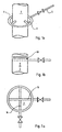
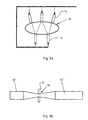
- FIG. 1a comprises an annular manifold placed around the pulp flow channel in a distance therefrom. connected by a number of feed pipes (at least four feed pipes) with the pulp flow channel so that the retention aid is discharged via said feed pipes in an even flow to the pulp flowing in the channel.
- FIG. 1b and 1c is to take e.g. two feed pipes crosswise through the flow channel and provide the part of the feed pipes which is left inside the flow channel with retention aid feed holes or slots, through which the retention aid flows in an even stream into the pulp, whereby the mixing result is to some extent better.
- retention aids are fed into the fiber suspension flow under a relatively small pressure difference.
- retention aids form their own flow channels or at least a distinct danger exists that they are channeled inside the fiber suspension flow.
- retention aid feeding it is commonly presumed that after the feeding point of the chemical there is a mixing apparatus that mixes the chemicals homogeneously into the fiber suspension.
- the amount of retention aid that is fed into the fiber suspension is chiefly based on practical knowledge from experience. This means that in practice retention aids are mixed into fiber suspension in an amount big enough to ensure the desired effect. In fact, this means a remarkable overdosing of retention chemicals (sometimes even by tens of percents) due to not homogeneous mixing.
- retention aids are delivered to paper mills, in addition to liquid form, also as powders which are used depending on the paper to be made and the material to be used in an amount of about 200 - 500 g per one paper ton.
- a retention aid in powder form is mixed into fresh water in a special mixing tank in a proportion of 1 kg of powder to about 200 liters of clean water. This is because retention aids are known to react with, that is to stick onto, all solid matter particles in the flow very quickly, in about a second, which means that the dilution liquid has to be as clean as possible. In other words, in this stage, per 1 ton of produced paper 40 - 100 liters of clean water is used for retention aid production.
- the consumption per day is, depending on the production of the paper machine, 10 - 100 cubic meters (here the production is estimated to be 250 - 1000 tons of paper per day). Nevertheless, this first dissolution stage is not the stage where water is used at the most, as in prior art processes this retention aid solution is further diluted into, e.g., one fifth of its concentration, which in practice means that for this so-called secondary dilution 200 - 500 liters of clean water is used per 1 paper ton. This results in a calculated daily consumption of 50 - 500 cubic meters of clean water per one paper machine.
- retention aid feed pipes 16 are arranged inside flow channel 2, said feed pipes having feed holes or feed slots 18 in the area inside the flow channel.
- retention aid is more efficiently mixed with the flowing fiber suspension, because the retention aid may be proportioned also into the center of the flow.
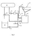
- Fig. 2 illustrates an arrangement of the short circulation of a paper machine partially according to both prior art and a preferred embodiment of the invention, mainly in view of retention aid introduction.
- the fiber suspension to be fed to the paper machine is diluted to applicable consistency in a wire pit 20 with white water from the paper machine 22, although a separate mixing tank may be utilized. Other adequate liquids may be used for dilution too, if desired, as for instance filtrate from a white water filter.
- the fiber suspension is guided by means of a pump 24 to centrifugal cleaning 26 and further to a gas separation tank 28.
- Gas-free fiber suspension is pumped by means of a headbox feed pump 30 into a headbox screen 32, and after that in a feeding-/mixing apparatus 34 a retention aid is added into the fiber suspension prior to transporting the fiber suspension to the headbox 36 of the paper machine 22.
- a headbox feed pump 30 into a headbox screen 32
- a feeding-/mixing apparatus 34 a retention aid is added into the fiber suspension prior to transporting the fiber suspension to the headbox 36 of the paper machine 22.
- Fig. 2 there is also a schematic illustration of the treatment of a retention aid prior to the retention aid is fed into the fiber suspension.
- the retention aid in liquid or powder form is mixed into fresh water, clean water in order to avoid flocculation, in a container 40, wherefrom the retention aid solution is proportioned by means of a pump 42 directly into a feeding-/mixing apparatus 34.
- the retention aid solution was either taken into a second mixing container where it was further diluted to a final concentration of about 0.05 - 0.1 %, or the corresponding dilution was carried out in the flow channel.
- Fig. 2 shows further a pipe 44 leading from the wire pit 20 of the paper machine to the mixer 34.
- white water is applied from wire pit 20 into the mixer 34 for further dilution of the retention chemical, which white water thus contains fines filtrated off the fiber suspension through the wire.
- filtrate from white water filter or some other filtrate obtained from the process may be used for the dilution.
- a pipe 48 Another additional possibility shown in Fig. 2 is a pipe 48, through which more clean water or fresh water may be introduced into the retention aid solution in order to dilute the solution, if desired.
- Fig. 3 illustrates schematically a mixing apparatus not forming part of the present invention.
- the mixing apparatus 34 according to Fig. 3 is, in fact, a nozzle comprising preferably an essentially conical casing 50, flanges 52 and 54 arranged into it and preferably, but not necessarily, placed at its opposite ends, and a conduit 56 for the retention chemical.
- the mixing apparatus 34 is connected via flange 52 to a dilution medium pipe (whip water pipe) and via flange 54 to the fiber suspension flow channel.
- the casing 50 of the mixing apparatus 34 is converging from flange 52 towards flange 54 inside of which is the opening 58 of the mixing apparatus.
- a purpose of the conical form of the casing 50 is to accelerate the medium flow in the mixing apparatus 34 so that the velocity of the jet discharging from the mixing apparatus 34 into the fiber suspension flow is at least three times, but preferably about five times the velocity of the fiber suspension flow. This velocity difference ensures that the retention chemical jet penetrates quickly enough and deep enough into the fiber suspension flow to be mixed with the fiber suspension essentially more homogeneously than in prior art embodiments.
- the retention chemical feeding conduit 56 is preferably tangential in order to ensure that retention aid discharging through opening 58 of.the mixing apparatus 34 into the fiber suspension flow is distributed homogeneously at least on the whole periphery of the opening 58. At the same time, tangential feeding ensures that the retention chemical is mixed into the whip water under minimum possible shear forces in order to prevent the polymeric chains of the chemical from degrading.
- Fig. 4 illustrates as a preferred embodiment of the present invention, wherein the mixing apparatus 34 of fig. 3 comprises a hollow annular member 60 arranged centrally inside the mixing apparatus 34, into which member the retention aid is guided via conduit 56.
- the member 60 essentially comprises two rotationally symmetrical shells 59 and 61 and possibly one end wall 62. Further, at the end of member 60, on the fiber suspension flow channel side, there is a preferably annular opening 64 provided, through which the retention chemical is allowed to be discharged into the fiber suspension.
- the retention chemical conduit 56 pierces the wall of the conical casing 50 of the mixing apparatus 34 and further leads via the annular space between the conical casing 50 and the member 60 into the member 60 through the outer shell 59, at the same time preferably carrying the member 60 in its place.
- the inner shell 61 restricting the member 60 is cylindrical and forms or comprises a pipe 62, through which part of the dilution medium flow i.e. whip water is allowed to discharge into the fiber suspension flow.
- the retention aid flow guided tangentially into member 60 turns in form of a spiral flow towards its own annular opening 64, through which the retention aid is discharged as a fan-shaped jet into the fiber suspension together with the dilution liquid discharging in this embodiment both from outside the opening 64 through the annular opening 58, and from inside the opening 64 through pipe 62.
- An additional purpose of member 60 is to further throttle the cross-sectional flow area of the mixing apparatus in order to insure a sufficient velocity difference between the retention aid flow and the fiber suspension flow.
- a second purpose of member 60 is to enable the mixing of the retention aid with the dilution liquid to take place essentially at the same time that the retention aid is being fed into the fiber suspension flow. The figure clearly shows that the retention aid is not in any contact with the dilution liquid before it is discharged through its opening 64 into the fiber-suspension flow channel.
- Fig. 5 illustrates a retention aid feeding-/mixing apparatus according to another preferred embodiment of the invention.
- the apparatus is exactly similar to the one of Fig. 4, but it clearly differs from previous apparatuses by both its coupling to the process and by its operational characteristics.
- the inner pipe 62 of member 60 is connected to the process via its own flow path 162 and the outer pipe of the apparatus 34, forming the wall of the conical casing 50, via its own flow path 144.
- Both flow paths 144 and 162 are provided with flow regulation devices 146 and 164, preferably valves.
- the flow pipe 144 functions as already stated before, but into the inner pipe 62 of member 60 it is now possible to introduce e.g.
- a retention aid component especially in question of a retention aid containing several components.
- a short-chain retention chemical might be mentioned, in case the retention aid is formed of a long-chain and a short-chain chemical. In that case, the long-chain chemical is supplied tangentially into member 60 earlier, through conduit 56 illustrated in Fig. 3 and 4. That is, liquids introduced through flow paths 144 and 162 may be of similar or different character, depending on the application.
- the retention chemical feed is very gentle compared to prior art methods of retention chemical introduction.
- the retention chemical in any case is formed of molecules composed of polymeric chains, these should be fed with additional water introduction as gently as possible, in order to prevent the very sensitive polymeric chains from breaking and, subsequently, in order to avoid a remarkable reduction in the effect of the retention chemical.
- the chemical is supplied in the apparatuses according to Fig. 4 and 5 as a fan-shaped jet into the water discharged through the annular opening 58, shearing forces between the water and the chemical solution are reduced to minimum.
- test results show that the utilization of the apparatus according to the invention improves wire retention by at least 10 %.
- the only explanations for the advantageous test results are more precise and more efficient mixing of the chemical and reduction in the degradation of the polymeric chains of the chemical during the mixing.
- a further additional modification of the feeding-/mixing apparatus according to the invention is to arrange at the end of the inner pipe of member 60 or at the end of pipe 62 arranged inside member 60 a nozzle head which closes the opening of pipe 62 at the axis, leaving an essentially annular slot between itself and the rims of the pipe opening.
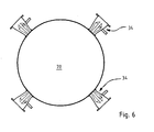
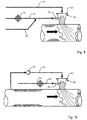
- Fig. 6 illustrates schematically a possible arrangement of the feeding-/mixing apparatuses 34 of Fig. 4 in connection with the fiber suspension feed pipe 70. In principle, this is carried out in a way demonstrated in Fig.1a.
- the only difference from the prior art method according to Fig. 1a - excluding the feeding of dilution liquid into the mixing apparatus and the point that as dilution liquid something else than clean water is used ⁇ is, in practice that the retention chemical solution discharging from the mixing apparatus 34 is planned to penetrate so deep into the fiber suspension flow in the feed pipe 70 that the retention chemical is mixed practically into the whole fiber suspension flow.
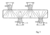
- Fig. 7 illustrates a preferred method of feeding a retention chemical from the mixing apparatus 34 into the fiber suspension flow.
- the mixing apparatuses 34 are arranged staggered opposite each other e.g. at the accept outlet 72 of the headbox screen or at another pipe of corresponding shape.
- the end of said outlet 72 facing the screen housing is arranged as essentially rectangular, from which point on, towards the feed pipe 70 leading to the headbox, it takes a round shape.
- the mixing apparatuses 34 are placed at the side walls of the outlet conduit 72 so that the retention aid jets discharging from the mixing apparatuses cover an essential part of the total cross section of conduit 72.
- conduit 72 Only at two comers of conduit 72 there is a small uncovered space left, which is not significant in respect of the mixing of the retention aid, as the fiber suspension flow when discharging from the screen is in such a heavy turbulence that the retention aid is mixed practically completely into the fiber suspension during the short interval available for that.
- the said problem has been avoided in the embodiment according to the figure by changing the shape of pipe 78 at the mixing point to be elliptical (preserving advantageously the same cross-sectional flow area).
- the mixing apparatuses 34 are placed on the periphery of the ellipse so that their jets are directed through the narrowest part of the ellipse, as shown in Fig. 8.
- the distance from the mixing apparatus 34 to the opposite side of pipe 78 is reduced by half compared to an analogous situation in a round pipe (Fig. 6).
- the amount and location of the mixing apparatuses 34 are chosen so that jets from the mixing apparatuses 34 form an essentially even cover on the cross section of the elliptic pipe 78.
- Fig. 8b illustrates an arrangement of the mixing apparatus/es in an elliptic pipe section 78 between cylindrical pipe sections 80' and 80".
- the reshaping of the cross section of a pipe from elliptic to cylindrical and vise versa is performed so that the cross sectional area remains constant, which means that also the flow speed, accordingly, remains constant.
- Fig. 9 illustrates the coupling of a mixing apparatus 34 fixed in a flow channel leading to the headbox with various pipe lines.
- retention aid solution produced in a solution tank 40 (Fig. 2) is transported to conduit 56 of the mixing apparatus 34 through pipe 43.
- Pipe 43 is provided with a filter 74 for separating from the solution the insoluble materials possibly left therein.
- additional dilution water preferably clean water, may be brought into the retention chemical solution through pipe 48.
- a suitable feeding liquid is introduced into the mixing apparatus 34 through pipe 44 fixed on flange 52, which feeding liquid may be white water from the wire pit according to an embodiment of Fig. 2, clear or turbid filtrate or some other liquid suitable for the purpose.
- Fig. 10 illustrates an alternative to the feeding liquid of Fig. 2 and 9.
- Fig. 9 illustrates a minor side flow from feed pipe 70 into pipe 44, which side flow is fed at an increased pressure by means of a pump 76 into the mixing apparatus 34.
- feeding liquid the same fiber suspension that is already being fed into the headbox is used.
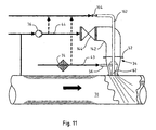
- Fig. 11 illustrates further the coupling of the feeding-/mixing apparatus of Fig. 5 with the rest of the process.
- the figure shows how white water from the wire pit, clear or turbid filtrate or some other liquid suitable for the purpose, or fiber suspension being fed to the headbox in principle exactly in accordance with Fig. 9 and 10, is supplied into the apparatus through flow path 144.
- the inner pipe 62 of member 60 of the apparatus 34 is connected to an outer flow path 162 which may lead either to a retention chemical solution tank 140.
- various sources of additional liquid e.g. white water, clear or turbid filtrate etc., or to a source of clean liquid.
- the figure illustrates how both flow paths 144 and 162 are provided with valves 146 and 164 for regulating the liquid flow in said flow paths in a desired way.
Landscapes
- Chemical & Material Sciences (AREA)
- Chemical Kinetics & Catalysis (AREA)
- Engineering & Computer Science (AREA)
- Manufacturing & Machinery (AREA)
- Dispersion Chemistry (AREA)
- Paper (AREA)
- Feeding, Discharge, Calcimining, Fusing, And Gas-Generation Devices (AREA)
- Infusion, Injection, And Reservoir Apparatuses (AREA)
- Fertilizers (AREA)
Abstract
Description
Claims (41)
- A method of mixing a liquid chemical into a second liquid in a mixing apparatus, whereina) an annular flow is formed of said second liquid in said mixing apparatus,b) said chemical is fed into said mixing apparatus, and guided inside said annular flow of said second liquid,c) the chemical is allowed to be mixed into said second liquid substantially simultaneously with the discharge of said chemical and said second liquid from said mixing apparatus into a fourth liquid.
- A method according to claim 1, characterized in positioning a member essentially concentrically inside said mixing apparatus and spaced from the inner walls of the apparatus, and introducing said chemical into said member tangentially in order to form a spiral-formed chemical flow.
- A method according to claim 2, characterized in that from inside the spiral-formed chemical flow a third flow is fed into the flow formed of said chemical flow and the flow formed of said second liquid.
- A method according to claim 1 or 3, characterized in that said second liquid is fresh water or clean water.
- A method according to claim 3, characterized in that said third flow is formed of fresh water or clean water.
- A method according to claim 3, characterized in that said third flow is formed of a chemical solution.
- A method according to claim 1, 2 or 3, characterized in that said chemical is a retention chemical used in paper manufacture or some other chemical at least partly comprising polymeric chains.
- A method according to claim 1, characterized in that said fourth liquid is fiber suspension flowing toward the paper machine.
- A method according to claim 6, characterized in that the chemical contained in said chemical solution is a retention chemical used in paper manufacture or some other chemical at least partly consisting of polymeric chains.
- A method according to claim 1, characterized in that stage c) is carried out by discharging said chemical flow and the annular flow formed of said second liquid into the fiber suspension flowing towards the headbox of a paper machine.
- A method according to claim 1, characterized in that said second liquid is circulation liquid from the paper mill, white water, clear filtrate, turbid filtrate or some other suitable non-clean liquid which is used as retention chemical feed liquid.
- A method according to claim 6, characterized in that said chemical solution is formed of a retention chemical solution or some other chemical at least partly consisting of polymeric chains.
- A method according to claim 3, characterized in that said third flow is formed of a chemical feed liquid, such as circulation water from the paper mill, white water, clear filtrate, turbid filtrate or some other non-clean liquid suitable for the purpose.
- A method according to claim 11 or to claims 11 and 13, characterized in that the mixture of said retention chemical solution and feed liquid is fed into the fiber suspension flow flowing towards the paper machine, between the headbox screen and the headbox of a paper machine.
- A method according to claim 1, characterized in that the feed liquid used is clear or turbid filtrate from an appropriate process apparatus, e. g. from the white water filter.
- A method according to claim 1, characterized in that in stages b) and c) the second liquid used, i. e. a so-called feed liquid, is fiber suspension led to the paper machine.
- A method according to claim 16, characterized in that the flow speed of the mixture of retention chemical solution and said second liquid fed into the fiber suspension led to the paper machine is at the feeding stage at least three times, preferably five times the flow speed of the fiber suspension led to the paper machine.
- A method according to claims 7 and 12, characterized in said retention chemical including two components, and carrying out said mixing of said components essentially when these are being fed into the fiber suspension flow flowing towards the paper machine.
- A method according to any one of the preceding claims, characterized in that at least one of said second and third flow is adjustable.
- A method according to claim 8 or 11, characterized in that the mixture of retention chemical solution and feed liquid is fed into the fiber suspension flow at least partly in form of a spiral jet.
- An apparatus for mixing a liquid chemical into a second liquid in a mixing apparatus (34) comprising at least a casing (50) with inlet conduits therein for the chemical to be mixed and the second liquid and one outlet conduit, wherein the apparatus (34) further comprisesa member (60) placed inside the casing (50) essentially concentrically with the casing, which member via its outer shell (59) separates inside said casing (50) an annular space between the shell (59) and the inner wall of the casing and a space inside said member (60) anda chemical feed conduit (56) connected with the space inside said shell (59), so that the chemical fed through conduit (56) flows through the space inside said member and the second liquid fed through its inlet flows in said annular space outside said member and the chemical is allowed to be mixed into said liquid simultaneously with discharge of said two liquids from said outlet conduit.
- An apparatus according to claim 21, characterized in that said chemical inlet conduit (56) is connected to said casing (50) and opens into said casing (50) interior in such a manner that the chemical fed via said inlet conduit (56) is caused to flow spirally within said casing (50).
- An apparatus according to claim 22, characterized in that said chemical inlet conduit is tangential.
- An apparatus according to claim 21 or 22 or 23, characterized in that said casing (50) is essentially rotationally symmetrical.
- An apparatus according to claim 21, characterized in that said shell (59) is rotationally symmetrical.
- An apparatus according to claim 21, characterized in that the annular space separated inside said casing (50) by the outer shell (59) of the member (60) is connected with feeding apparatus (44, 144) of a second liquid.
- An apparatus according to claim 21, characterized in that inside member (60), inside the outer shell (59), there is a second shell (61) which together with the shell (59) provides an annular space inside the member (60).
- An apparatus according to claim 21 or 27, characterized in that the chemical conduit (56) opens tangentially into the inner side of the shell (59).
- An apparatus according to claim 27, characterized in that the space restricted by the shell (61) is rotationally symmetrical and connected with an inlet duct (44, 144) of a second liquid.
- An apparatus according to claim 27, characterized in that the space restricted by and inside the shell (61) is connected with an inlet duct (164) of a third liquid.
- An apparatus according to claim 21, characterized in the outer shell (59) of the member (60) having an extension in the axial direction of the apparatus (34), and said extension being adjustable .
- An apparatus according to claim 27, characterized in the inner shell (61) of the member (60) having an extension in the axial direction of the apparatus (34), and said extension being adjustable.
- An apparatus according to claim 29, characterized in that in the inlet duct (44, 144) of a second liquid there is a flow-regulating device (146).
- An apparatus according to claim 30, characterized in that in the inlet duct (162) of a third liquid there is a flow-regulating device (164).
- An apparatus according to any of claims 21 - 34, characterized in that said mixing apparatus (34) is used for mixing a retention chemical into the fiber suspension flow fed into the headbox (36) of a paper machine (22), said mixing apparatus (34) being connected to devices (40) for the pre-treatment of the retention chemical prior to its introduction in said mixing apparatus.
- An apparatus according to any one of claims 21 - 34, characterized in that said mixing apparatus (34) is arranged in combination with a paper machine approach flow system comprising at least a gas separation tank (28), a headbox screen (32), a feed pipe (70) leading from the headbox screen (32) to the headbox (36), a headbox (36) of a paper machine (22), devices (40) for pre-treatment of the retention chemical, devices for feeding the retention chemical into the fiber suspension flow flowing towards the headbox (36) and devices (46) for recovering the white water, the retention chemical feed devices comprising said mixing apparatus (34), into which both the retention chemical and the feeding liquid are introduced.
- A feeding system according to claim 36, characterized in that said mixing apparatus (34) is connected via a pipe (44) with the devices (46) for recovering the white water in order to utilize the white water as a retention chemical feeding liquid.
- A feeding system according to claim 36, characterized in that the headbox screen (32) is provided with a slot drum, whereby said mixing apparatus (34) is fixed on the feed pipe (70) between the headbox screen (32) and the headbox (36).
- An apparatus according to claim 38, characterized in that said mixing apparatus (34) is fixed on the accept conduit (72) of the headbox screen (32).
- An apparatus according to claim 38, characterized in that the accept conduit (72) of the headbox screen (32) is essentially rectangular.
- An apparatus according to claim 39, characterized in that said mixing apparatuses (34) are fixed at two sides of said accept conduit (72) of the headbox screen (32).
Priority Applications (1)
| Application Number | Priority Date | Filing Date | Title |
|---|---|---|---|
| EP02005215A EP1219344B1 (en) | 1998-02-26 | 1999-02-24 | Method and apparatus for feeding a chemical into a liquid flow |
Applications Claiming Priority (3)
| Application Number | Priority Date | Filing Date | Title |
|---|---|---|---|
| FI980437A FI108802B (en) | 1998-02-26 | 1998-02-26 | Method and apparatus for feeding a chemical into a liquid stream and feeding arrangement for a paper machine |
| FI980437 | 1998-02-26 | ||
| PCT/FI1999/000145 WO1999043887A1 (en) | 1998-02-26 | 1999-02-24 | Method and apparatus for feeding a chemical into a liquid flow |
Related Child Applications (1)
| Application Number | Title | Priority Date | Filing Date |
|---|---|---|---|
| EP02005215A Division EP1219344B1 (en) | 1998-02-26 | 1999-02-24 | Method and apparatus for feeding a chemical into a liquid flow |
Publications (2)
| Publication Number | Publication Date |
|---|---|
| EP1064427A1 EP1064427A1 (en) | 2001-01-03 |
| EP1064427B1 true EP1064427B1 (en) | 2004-03-24 |
Family
ID=8551025
Family Applications (2)
| Application Number | Title | Priority Date | Filing Date |
|---|---|---|---|
| EP99936102A Expired - Lifetime EP1064427B1 (en) | 1998-02-26 | 1999-02-24 | Method and apparatus for feeding a chemical into a liquid flow |
| EP02005215A Expired - Lifetime EP1219344B1 (en) | 1998-02-26 | 1999-02-24 | Method and apparatus for feeding a chemical into a liquid flow |
Family Applications After (1)
| Application Number | Title | Priority Date | Filing Date |
|---|---|---|---|
| EP02005215A Expired - Lifetime EP1219344B1 (en) | 1998-02-26 | 1999-02-24 | Method and apparatus for feeding a chemical into a liquid flow |
Country Status (10)
| Country | Link |
|---|---|
| US (1) | US6659636B1 (en) |
| EP (2) | EP1064427B1 (en) |
| JP (1) | JP4601165B2 (en) |
| KR (1) | KR100627816B1 (en) |
| AT (2) | ATE349272T1 (en) |
| BR (1) | BR9908306B1 (en) |
| CA (1) | CA2321863C (en) |
| DE (2) | DE69934611T2 (en) |
| FI (1) | FI108802B (en) |
| WO (1) | WO1999043887A1 (en) |
Cited By (6)
| Publication number | Priority date | Publication date | Assignee | Title |
|---|---|---|---|---|
| WO2011110742A1 (en) | 2010-03-10 | 2011-09-15 | Wetend Technologies Oy | A method and apparatus for mixing various flows into a process liquid flow |
| WO2011110744A2 (en) | 2010-03-10 | 2011-09-15 | Upm-Kymmene Corporation | A method and reactor for in-line production of calcium carbonate into the production process of a fibrous web |
| WO2011110745A2 (en) | 2010-03-10 | 2011-09-15 | Wetend Technologies Oy | A method and a reactor for mixing one or more chemicals into a process liquid flow |
| WO2014128355A1 (en) | 2013-02-22 | 2014-08-28 | Wetend Technologies Oy | An arrangement for mixing a fluid to a process liquid and a method of operating the arrangement |
| WO2014128358A1 (en) | 2013-02-22 | 2014-08-28 | Wetend Technologies Oy | An arrangement for and a method of manufacturing a fibrous web |
| WO2014174155A1 (en) | 2013-04-26 | 2014-10-30 | Wetend Technologies Oy | A method of providing fiber web making furnish with filler, and paper or paper board |
Families Citing this family (53)
| Publication number | Priority date | Publication date | Assignee | Title |
|---|---|---|---|---|
| US6193406B1 (en) * | 1996-12-20 | 2001-02-27 | Andritz-Ahlstrom Oy | Method and apparatus for mixing pulp a suspension with a fluid medium with a freely rotatable mixing rotor |
| DE10050109A1 (en) * | 2000-10-09 | 2002-04-11 | Voith Paper Patent Gmbh | Preparation of a fiber suspension, as paper/cardboard pulp, has a mixing pipe for the main mixed suspension flow with an elbow where an additional suspension is injected with a bulking agent |
| DE20321803U1 (en) * | 2003-04-09 | 2010-04-08 | Voith Patent Gmbh | Arrangement for feeding a second liquid to a paper pulp suspension |
| US6913457B2 (en) * | 2003-07-30 | 2005-07-05 | American Air Liquide, Inc. | Method and apparatus for optimized CO post-combustion in low NOx combustion processes |
| FI115148B (en) * | 2003-10-08 | 2005-03-15 | Wetend Technologies Oy | A method and apparatus for introducing a chemical into a liquid stream |
| US7481979B2 (en) * | 2004-04-20 | 2009-01-27 | Akribio Corp. | Multiport cofinger microreactor stopper and device |
| FI123249B (en) * | 2004-07-15 | 2013-01-15 | Wetend Technologies Oy | Method and apparatus for feeding a chemical to a liquid stream |
| FI116473B (en) * | 2004-07-16 | 2005-11-30 | Wetend Technologies Oy | A method and apparatus for feeding chemicals into a process fluid stream |
| FR2878171B1 (en) * | 2004-11-19 | 2007-03-09 | Solvay | REACTOR AND METHOD FOR THE REACTION BETWEEN AT LEAST TWO GASES IN THE PRESENCE OF A LIQUID PHASE |
| DE102004063005A1 (en) | 2004-12-22 | 2006-07-13 | Basf Ag | Process for the production of paper, cardboard and cardboard |
| DE102004063000A1 (en) * | 2004-12-22 | 2006-07-06 | Basf Ag | Method for sizing paper |
| FI20055206A7 (en) * | 2005-05-02 | 2006-11-03 | Metso Paper Inc | Method for mixing liquid flows with each other and mixer |
| US7938934B2 (en) * | 2006-01-25 | 2011-05-10 | Nalco Company | ASA emulsification with ultrasound |
| US7550060B2 (en) * | 2006-01-25 | 2009-06-23 | Nalco Company | Method and arrangement for feeding chemicals into a process stream |
| US8440052B2 (en) * | 2006-01-25 | 2013-05-14 | Nalco Company | Method and arrangement for feeding chemicals into a pulp process stream |
| EP2087169A1 (en) * | 2006-10-31 | 2009-08-12 | Basf Se | Method for producing a multi layer fiber web from cellulose fibers |
| FI123392B (en) * | 2008-02-22 | 2013-03-28 | Upm Kymmene Oyj | Method for Precipitation of Calcium Carbonate in a Fibrous Web Process and Fiber Machine Machine Approach |
| JP5441244B2 (en) * | 2009-02-25 | 2014-03-12 | ハイモ株式会社 | Paper making method |
| DE102009001731A1 (en) | 2009-03-23 | 2010-09-30 | Voith Patent Gmbh | Method for adjusting a basis weight cross-section of a fibrous or nonwoven web and machine for producing a fibrous or nonwoven web |
| JP5570004B2 (en) * | 2009-05-28 | 2014-08-13 | ハイモ株式会社 | Paper making method |
| DE102009045916A1 (en) | 2009-10-22 | 2011-04-28 | Voith Patent Gmbh | Device useful for sectional dosing of fluid medium into further fluid medium deployable over dispensing region extending in transverse direction, comprises device for transverse distribution, dosing device, and device for mixing |
| JP5570005B2 (en) * | 2009-11-30 | 2014-08-13 | ハイモ株式会社 | Paper making method |
| JP5584505B2 (en) * | 2010-03-30 | 2014-09-03 | 日本製紙株式会社 | Paper manufacturing method |
| DE102010028572A1 (en) | 2010-05-05 | 2011-11-10 | Voith Patent Gmbh | Method for admixing a liquid chemical to a process stream and apparatus |
| DE102010028577A1 (en) | 2010-05-05 | 2011-11-10 | Voith Patent Gmbh | Method for adding a chemical to a process stream |
| BR112012031995B1 (en) * | 2010-06-14 | 2020-02-27 | Dow Global Technologies Llc | STATIC REACTIVE JET MIXER |
| JP5637527B2 (en) * | 2010-07-08 | 2014-12-10 | ハイモ株式会社 | Paper making method |
| AU2011346139B2 (en) * | 2010-12-22 | 2016-07-14 | Institute Of National Colleges Of Technology, Japan | Fluid mixer and fluid mixing method |
| US10086694B2 (en) | 2011-09-16 | 2018-10-02 | Gaseous Fuel Systems, Corp. | Modification of an industrial vehicle to include a containment area and mounting assembly for an alternate fuel |
| US9738154B2 (en) | 2011-10-17 | 2017-08-22 | Gaseous Fuel Systems, Corp. | Vehicle mounting assembly for a fuel supply |
| US10290381B2 (en) * | 2011-12-30 | 2019-05-14 | Ge-Hitachi Nuclear Energy Americas Llc | Method and apparatus for a high-temperature deposition solution injector |
| FI20125338L (en) | 2012-03-26 | 2013-09-27 | Wetend Technologies Oy | Method and apparatus for feeding two chemicals with opposite electrical charges into a process fluid stream |
| SE538250C2 (en) | 2012-11-09 | 2016-04-12 | In-line production method for papermaking | |
| SE538246C2 (en) | 2012-11-09 | 2016-04-12 | Cardboard layers in an in-line production process | |
| US9761336B2 (en) | 2012-12-20 | 2017-09-12 | Ge-Hitachi Nuclear Energy Americas Llc | Insulated solution injector, system including the same, and method of injecting using the same |
| US9696066B1 (en) | 2013-01-21 | 2017-07-04 | Jason E. Green | Bi-fuel refrigeration system and method of retrofitting |
| SE537737C2 (en) | 2013-03-01 | 2015-10-06 | Stora Enso Oyj | In-Line Preparation of Silica for Retention Purposes in Paper or Cardboard Manufacturing Process |
| CN103223315B (en) * | 2013-05-07 | 2015-05-20 | 烟台杰瑞石油服务集团股份有限公司 | Solid-liquid mixing device |
| US9845744B2 (en) | 2013-07-22 | 2017-12-19 | Gaseous Fuel Systems, Corp. | Fuel mixture system and assembly |
| WO2015152283A1 (en) * | 2014-03-31 | 2015-10-08 | 日本製紙株式会社 | Calcium-carbonate-microparticle/fiber composite and manufacturing method therefor |
| US9931929B2 (en) | 2014-10-22 | 2018-04-03 | Jason Green | Modification of an industrial vehicle to include a hybrid fuel assembly and system |
| EP3026172A1 (en) | 2014-11-25 | 2016-06-01 | UPM-Kymmene Corporation | Method for treating a stream of a deinking plant and its use and product |
| US9885318B2 (en) * | 2015-01-07 | 2018-02-06 | Jason E Green | Mixing assembly |
| US10515729B2 (en) | 2015-11-04 | 2019-12-24 | Ge-Hitachi Nuclear Energy Americas Llc | Insulated solution injector including an insulating liner, system including the same, and method of injecting using the same |
| GB2561235B (en) * | 2017-04-07 | 2022-02-23 | Oil & Gas Measurement Ltd | Smart entrainment atomisation mixing system |
| CA3063628A1 (en) | 2017-07-20 | 2019-01-24 | Clariant International Ltd | Demulsifiers and a method of using demulsifiers for breaking emulsions of water and crude oil |
| FR3077011B1 (en) * | 2018-01-24 | 2020-02-14 | Capsum | DEVICE FOR PRODUCING A DISPERSION, ASSEMBLY AND ASSOCIATED METHOD |
| JP7017287B2 (en) * | 2018-04-11 | 2022-02-08 | アクアス株式会社 | Diluting addition method of chemical solution |
| JP7328001B2 (en) * | 2019-05-20 | 2023-08-16 | アクアス株式会社 | How to dilute and add chemicals |
| KR20200141551A (en) | 2019-06-10 | 2020-12-21 | 하월영 | The Aronia noodle making method |
| EP3757288B1 (en) | 2019-06-28 | 2022-04-27 | Wetend Technologies Oy | A method of and an arrangement for adding a chemical to an approach flow system of a fiber web machine |
| EP3839136A1 (en) | 2019-12-20 | 2021-06-23 | Wetend Technologies Oy | A method of and an arrangement for adding at least one additional stock component to an approach flow system of a fiber web machine and headbox feed pipe |
| CN112726341B (en) * | 2020-12-30 | 2022-05-17 | 中电建路桥集团有限公司 | Highway platform back foam light soil backfills roadbed construction device |
Family Cites Families (44)
| Publication number | Priority date | Publication date | Assignee | Title |
|---|---|---|---|---|
| US945143A (en) * | 1909-07-28 | 1910-01-04 | Iacques Szamek | Apparatus for mixing liquids. |
| US1496345A (en) * | 1923-09-28 | 1924-06-03 | Frank E Lichtenthaeler | Apparatus for mixing liquids |
| NL75972C (en) * | 1950-10-13 | 1900-01-01 | ||
| US2831754A (en) * | 1954-05-10 | 1958-04-22 | Jones & Laughlin Steel Corp | Solvent extraction process |
| CH365708A (en) * | 1957-11-27 | 1962-11-30 | Stamicarbon | Method for introducing a liquid into a turbulent second liquid via a pipe opening into the latter, wherein the second liquid can result in an undesirable reaction with the former if it penetrates the supply pipe |
| US3251653A (en) * | 1962-11-13 | 1966-05-17 | Union Carbide Corp | Double-cone reactor for vapor-phase reactions |
| DE1258835B (en) * | 1964-08-28 | 1968-01-18 | James R Lage Dr | Mixing device |
| US3794299A (en) * | 1971-09-23 | 1974-02-26 | Chem Trol Pollution Services | Centrifugal reactor |
| SE387862B (en) * | 1974-09-13 | 1976-09-20 | G A Staaf | PIPE MIXER, INCLUDING A HOUSE DESIGNED AS A ROTARY BODY, TWO OR MORE CONNECTED PIPE PIPES FOR SUPPLYING THE MIXING COMPONENTS, AS WELL AS A TO THE HOUSE AXIALLY CONNECTED |
| US4053142A (en) * | 1976-06-11 | 1977-10-11 | Eastman Kodak Company | Nonmechanical shearing mixer |
| CA1110228A (en) * | 1978-03-13 | 1981-10-06 | Borgeir Skaugen | Variable venturi dispersing and mixing device |
| JPS5916106Y2 (en) * | 1978-06-20 | 1984-05-12 | 正博 武田 | self-contained mixing equipment |
| FI63613C (en) * | 1981-06-05 | 1983-07-11 | Enso Gutzeit Oy | PAPER MUSCLE PENSION |
| US4586825A (en) * | 1982-06-22 | 1986-05-06 | Asadollah Hayatdavoudi | Fluid agitation system |
| US4498819A (en) * | 1982-11-08 | 1985-02-12 | Conoco Inc. | Multipoint slurry injection junction |
| US4519423A (en) * | 1983-07-08 | 1985-05-28 | University Of Southern California | Mixing apparatus using a noncircular jet of small aspect ratio |
| JPS61118120A (en) * | 1984-11-12 | 1986-06-05 | Toyota Motor Corp | Mixer of various kinds of fluid |
| GB2177618B (en) * | 1985-07-13 | 1989-07-19 | Adrian Philip Boyes | Gas/liquid contacting |
| EP0213329B1 (en) * | 1985-07-30 | 1991-10-02 | Hartmut Wolf | Pulverizing device |
| US4673006A (en) * | 1985-08-12 | 1987-06-16 | Herschel Corporation (Delaware Corp.) | Apparatus and method for removing liquid from and cleaning a container |
| US4913775A (en) * | 1986-01-29 | 1990-04-03 | Allied Colloids Ltd. | Production of paper and paper board |
| US4781467A (en) * | 1986-04-09 | 1988-11-01 | Cca, Inc. | Foam-generating apparatus |
| US4705405A (en) * | 1986-04-09 | 1987-11-10 | Cca, Inc. | Mixing apparatus |
| US4861165A (en) * | 1986-08-20 | 1989-08-29 | Beloit Corporation | Method of and means for hydrodynamic mixing |
| SE455795B (en) * | 1986-12-03 | 1988-08-08 | Mo Och Domsjoe Ab | PROCEDURE AND DEVICE FOR PREPARING FILLING PAPER |
| US4790666A (en) * | 1987-02-05 | 1988-12-13 | Ecolab Inc. | Low-shear, cyclonic mixing apparatus and method of using |
| US4753535A (en) * | 1987-03-16 | 1988-06-28 | Komax Systems, Inc. | Motionless mixer |
| US4761077A (en) * | 1987-09-28 | 1988-08-02 | Barrett, Haentjens & Co. | Mixing apparatus |
| JP2689121B2 (en) * | 1988-02-10 | 1997-12-10 | 東レ・ダウコーニング・シリコーン株式会社 | Method and apparatus for producing viscous liquid water dispersion |
| CH675697A5 (en) * | 1988-09-26 | 1990-10-31 | Sandoz Ag | |
| ES2048968T3 (en) * | 1989-03-20 | 1994-04-01 | Medite Europ | APPARATUS AND METHOD OF MANUFACTURE OF SYNTHETIC BOARDS, INCLUDING FIREPROOF BOARDS. |
| CA2059529C (en) * | 1989-07-29 | 2001-11-27 | Raisio Chemicals Uk Ltd. | Treatment of fibrous materials |
| FR2665088B1 (en) * | 1990-07-27 | 1992-10-16 | Air Liquide | METHOD AND DEVICE FOR MIXING TWO GASES. |
| FR2678927B1 (en) * | 1991-07-11 | 1993-11-19 | Maroc Chimie | PROCESS AND PLANT FOR PRODUCING GRANULATED TRIPLE SUPERPHOSPHATE (TSP). |
| EP0541457A1 (en) * | 1991-11-04 | 1993-05-12 | Eastman Kodak Company | Apparatus and method for the on-line control of the filler content of a paper product |
| FR2688709B1 (en) * | 1992-03-23 | 1994-09-02 | Schlumberger Cie Dowell | CONTINUOUS LIQUID ADDITIVE MIXER IN A FLUID. |
| SE504247C2 (en) * | 1994-03-24 | 1996-12-16 | Gaevle Galvan Tryckkaerl Ab | Vessels for treating fluid |
| GB2292158B (en) * | 1994-07-26 | 1998-12-09 | Roe Lee Paper Chemicals Compan | Sizing method |
| US5653801A (en) * | 1995-04-06 | 1997-08-05 | University Of Maryland Baltimore County | Method for reducing contamination in semiconductor by selenium doping |
| FR2732902B1 (en) * | 1995-04-13 | 1997-05-23 | Inst Francais Du Petrole | DEVICE FOR MIXING HIGH SPEED FLUIDS |
| CA2168682A1 (en) * | 1995-06-02 | 1996-12-03 | David M. Harmon | Method and apparatus for reducing blowline obstructions during production of cellulosic composites |
| EP0766996B1 (en) * | 1995-10-05 | 2000-03-08 | Sulzer Chemtech AG | Apparatus for mixing a low viscosity fluid with a high viscosity fluid |
| FI104653B (en) * | 1997-02-18 | 2000-03-15 | Ahlstrom Machinery Oy | Method for determining the properties of a pulp |
| FI105407B (en) * | 1999-05-27 | 2000-08-15 | Valmet Corp | Inlet box in a papermaking machine or cardboard making machine |
-
1998
- 1998-02-26 FI FI980437A patent/FI108802B/en not_active IP Right Cessation
-
1999
- 1999-02-24 DE DE69934611T patent/DE69934611T2/en not_active Expired - Lifetime
- 1999-02-24 AT AT02005215T patent/ATE349272T1/en active
- 1999-02-24 BR BRPI9908306-0A patent/BR9908306B1/en not_active IP Right Cessation
- 1999-02-24 EP EP99936102A patent/EP1064427B1/en not_active Expired - Lifetime
- 1999-02-24 WO PCT/FI1999/000145 patent/WO1999043887A1/en not_active Ceased
- 1999-02-24 KR KR1020007009525A patent/KR100627816B1/en not_active Expired - Fee Related
- 1999-02-24 US US09/622,872 patent/US6659636B1/en not_active Expired - Lifetime
- 1999-02-24 DE DE69915810T patent/DE69915810T2/en not_active Expired - Lifetime
- 1999-02-24 EP EP02005215A patent/EP1219344B1/en not_active Expired - Lifetime
- 1999-02-24 CA CA002321863A patent/CA2321863C/en not_active Expired - Fee Related
- 1999-02-24 AT AT99936102T patent/ATE262617T1/en active
- 1999-02-24 JP JP2000533619A patent/JP4601165B2/en not_active Expired - Fee Related
Cited By (11)
| Publication number | Priority date | Publication date | Assignee | Title |
|---|---|---|---|---|
| WO2011110742A1 (en) | 2010-03-10 | 2011-09-15 | Wetend Technologies Oy | A method and apparatus for mixing various flows into a process liquid flow |
| WO2011110744A2 (en) | 2010-03-10 | 2011-09-15 | Upm-Kymmene Corporation | A method and reactor for in-line production of calcium carbonate into the production process of a fibrous web |
| WO2011110745A2 (en) | 2010-03-10 | 2011-09-15 | Wetend Technologies Oy | A method and a reactor for mixing one or more chemicals into a process liquid flow |
| CN103025414A (en) * | 2010-03-10 | 2013-04-03 | 韦坦德科技公司 | A method and a reactor for mixing one or more chemicals into a process liquid flow |
| WO2014128355A1 (en) | 2013-02-22 | 2014-08-28 | Wetend Technologies Oy | An arrangement for mixing a fluid to a process liquid and a method of operating the arrangement |
| WO2014128358A1 (en) | 2013-02-22 | 2014-08-28 | Wetend Technologies Oy | An arrangement for and a method of manufacturing a fibrous web |
| CN105392554A (en) * | 2013-02-22 | 2016-03-09 | 芬兰温德造纸湿部技术公司 | An arrangement for mixing a fluid to a process liquid and a method of operating the arrangement |
| EP3075903A1 (en) | 2013-02-22 | 2016-10-05 | Wetend Technologies Oy | An arrangement for and a method of manufacturing a fibrous web |
| US9649607B2 (en) | 2013-02-22 | 2017-05-16 | Wetend Technologies Oy | Arrangement for mixing a fluid to a process liquid and a method of operating the arrangement |
| CN105392554B (en) * | 2013-02-22 | 2017-07-21 | 芬兰温德造纸湿部技术公司 | For making the device that fluid is mixed with process liquids and the method for operating the device |
| WO2014174155A1 (en) | 2013-04-26 | 2014-10-30 | Wetend Technologies Oy | A method of providing fiber web making furnish with filler, and paper or paper board |
Also Published As
| Publication number | Publication date |
|---|---|
| DE69934611T2 (en) | 2007-10-04 |
| EP1219344A3 (en) | 2004-08-25 |
| BR9908306B1 (en) | 2009-05-05 |
| DE69934611D1 (en) | 2007-02-08 |
| KR100627816B1 (en) | 2006-09-25 |
| EP1064427A1 (en) | 2001-01-03 |
| CA2321863A1 (en) | 1999-09-02 |
| JP4601165B2 (en) | 2010-12-22 |
| ATE262617T1 (en) | 2004-04-15 |
| KR20010041394A (en) | 2001-05-15 |
| WO1999043887A1 (en) | 1999-09-02 |
| BR9908306A (en) | 2001-09-04 |
| EP1219344A2 (en) | 2002-07-03 |
| FI980437A0 (en) | 1998-02-26 |
| FI108802B (en) | 2002-03-28 |
| DE69915810D1 (en) | 2004-04-29 |
| DE69915810T2 (en) | 2005-01-27 |
| CA2321863C (en) | 2005-11-22 |
| US6659636B1 (en) | 2003-12-09 |
| ATE349272T1 (en) | 2007-01-15 |
| JP2002505179A (en) | 2002-02-19 |
| EP1219344B1 (en) | 2006-12-27 |
| FI980437L (en) | 1999-08-27 |
Similar Documents
| Publication | Publication Date | Title |
|---|---|---|
| EP1064427B1 (en) | Method and apparatus for feeding a chemical into a liquid flow | |
| US7758725B2 (en) | Method of mixing a paper making chemical into a fiber suspension flow | |
| EP0256965B1 (en) | Method of and means for hydrodynamic mixing | |
| US4964733A (en) | Method of and means for hydrodynamic mixing | |
| US9616399B2 (en) | Method for feeding chemical into a liquid flow | |
| US20120255620A1 (en) | Method and apparatus for feeding chemical into a liquid flow | |
| GB2141942A (en) | Mixing apparatus | |
| EP2830749B1 (en) | A method and an apparatus for mixing chemicals having opposite electric charges into a process liquid flow | |
| FI110015B (en) | Method and apparatus for feeding chemicals into liquid flows | |
| FI111284B (en) | Method and apparatus for feeding a chemical into a liquid stream | |
| FI111397B (en) | A method and apparatus for feeding a chemical to a fiber suspension | |
| EP0840820B1 (en) | Method and apparatus for bleaching pulp with a gaseous bleaching reagent |
Legal Events
| Date | Code | Title | Description |
|---|---|---|---|
| PUAI | Public reference made under article 153(3) epc to a published international application that has entered the european phase |
Free format text: ORIGINAL CODE: 0009012 |
|
| 17P | Request for examination filed |
Effective date: 20000901 |
|
| AK | Designated contracting states |
Kind code of ref document: A1 Designated state(s): AT DE FR GB SE |
|
| RAP1 | Party data changed (applicant data changed or rights of an application transferred) |
Owner name: WETEND TECHNOLOGIES OY |
|
| 17Q | First examination report despatched |
Effective date: 20021017 |
|
| GRAH | Despatch of communication of intention to grant a patent |
Free format text: ORIGINAL CODE: EPIDOS IGRA |
|
| GRAS | Grant fee paid |
Free format text: ORIGINAL CODE: EPIDOSNIGR3 |
|
| GRAA | (expected) grant |
Free format text: ORIGINAL CODE: 0009210 |
|
| AK | Designated contracting states |
Kind code of ref document: B1 Designated state(s): AT DE FR GB SE |
|
| REG | Reference to a national code |
Ref country code: GB Ref legal event code: FG4D |
|
| REF | Corresponds to: |
Ref document number: 69915810 Country of ref document: DE Date of ref document: 20040429 Kind code of ref document: P |
|
| REG | Reference to a national code |
Ref country code: SE Ref legal event code: TRGR |
|
| ET | Fr: translation filed | ||
| PGFP | Annual fee paid to national office [announced via postgrant information from national office to epo] |
Ref country code: GB Payment date: 20050118 Year of fee payment: 7 |
|
| PLBE | No opposition filed within time limit |
Free format text: ORIGINAL CODE: 0009261 |
|
| STAA | Information on the status of an ep patent application or granted ep patent |
Free format text: STATUS: NO OPPOSITION FILED WITHIN TIME LIMIT |
|
| 26N | No opposition filed |
Effective date: 20041228 |
|
| PG25 | Lapsed in a contracting state [announced via postgrant information from national office to epo] |
Ref country code: GB Free format text: LAPSE BECAUSE OF NON-PAYMENT OF DUE FEES Effective date: 20060224 |
|
| GBPC | Gb: european patent ceased through non-payment of renewal fee |
Effective date: 20060224 |
|
| REG | Reference to a national code |
Ref country code: FR Ref legal event code: PLFP Year of fee payment: 17 |
|
| PGFP | Annual fee paid to national office [announced via postgrant information from national office to epo] |
Ref country code: FR Payment date: 20150219 Year of fee payment: 17 Ref country code: SE Payment date: 20150218 Year of fee payment: 17 |
|
| PGFP | Annual fee paid to national office [announced via postgrant information from national office to epo] |
Ref country code: AT Payment date: 20160218 Year of fee payment: 18 |
|
| REG | Reference to a national code |
Ref country code: SE Ref legal event code: EUG |
|
| REG | Reference to a national code |
Ref country code: FR Ref legal event code: ST Effective date: 20161028 |
|
| PG25 | Lapsed in a contracting state [announced via postgrant information from national office to epo] |
Ref country code: SE Free format text: LAPSE BECAUSE OF NON-PAYMENT OF DUE FEES Effective date: 20160225 |
|
| PG25 | Lapsed in a contracting state [announced via postgrant information from national office to epo] |
Ref country code: FR Free format text: LAPSE BECAUSE OF NON-PAYMENT OF DUE FEES Effective date: 20160229 |
|
| REG | Reference to a national code |
Ref country code: AT Ref legal event code: MM01 Ref document number: 262617 Country of ref document: AT Kind code of ref document: T Effective date: 20170224 |
|
| PG25 | Lapsed in a contracting state [announced via postgrant information from national office to epo] |
Ref country code: AT Free format text: LAPSE BECAUSE OF NON-PAYMENT OF DUE FEES Effective date: 20170224 |
|
| PGFP | Annual fee paid to national office [announced via postgrant information from national office to epo] |
Ref country code: DE Payment date: 20180219 Year of fee payment: 20 |
|
| REG | Reference to a national code |
Ref country code: DE Ref legal event code: R071 Ref document number: 69915810 Country of ref document: DE |