EP1064143B1 - Liner and method for lining a pipeline - Google Patents
Liner and method for lining a pipeline Download PDFInfo
- Publication number
- EP1064143B1 EP1064143B1 EP99910542A EP99910542A EP1064143B1 EP 1064143 B1 EP1064143 B1 EP 1064143B1 EP 99910542 A EP99910542 A EP 99910542A EP 99910542 A EP99910542 A EP 99910542A EP 1064143 B1 EP1064143 B1 EP 1064143B1
- Authority
- EP
- European Patent Office
- Prior art keywords
- liner
- tube
- pipe
- adhesive
- profile
- Prior art date
- Legal status (The legal status is an assumption and is not a legal conclusion. Google has not performed a legal analysis and makes no representation as to the accuracy of the status listed.)
- Expired - Lifetime
Links
Images


Classifications
-
- B—PERFORMING OPERATIONS; TRANSPORTING
- B29—WORKING OF PLASTICS; WORKING OF SUBSTANCES IN A PLASTIC STATE IN GENERAL
- B29C—SHAPING OR JOINING OF PLASTICS; SHAPING OF MATERIAL IN A PLASTIC STATE, NOT OTHERWISE PROVIDED FOR; AFTER-TREATMENT OF THE SHAPED PRODUCTS, e.g. REPAIRING
- B29C63/00—Lining or sheathing, i.e. applying preformed layers or sheathings of plastics; Apparatus therefor
- B29C63/26—Lining or sheathing of internal surfaces
- B29C63/34—Lining or sheathing of internal surfaces using tubular layers or sheathings
- B29C63/36—Lining or sheathing of internal surfaces using tubular layers or sheathings being turned inside out
-
- F—MECHANICAL ENGINEERING; LIGHTING; HEATING; WEAPONS; BLASTING
- F16—ENGINEERING ELEMENTS AND UNITS; GENERAL MEASURES FOR PRODUCING AND MAINTAINING EFFECTIVE FUNCTIONING OF MACHINES OR INSTALLATIONS; THERMAL INSULATION IN GENERAL
- F16L—PIPES; JOINTS OR FITTINGS FOR PIPES; SUPPORTS FOR PIPES, CABLES OR PROTECTIVE TUBING; MEANS FOR THERMAL INSULATION IN GENERAL
- F16L55/00—Devices or appurtenances for use in, or in connection with, pipes or pipe systems
- F16L55/16—Devices for covering leaks in pipes or hoses, e.g. hose-menders
- F16L55/162—Devices for covering leaks in pipes or hoses, e.g. hose-menders from inside the pipe
- F16L55/165—Devices for covering leaks in pipes or hoses, e.g. hose-menders from inside the pipe a pipe or flexible liner being inserted in the damaged section
- F16L55/1656—Devices for covering leaks in pipes or hoses, e.g. hose-menders from inside the pipe a pipe or flexible liner being inserted in the damaged section materials for flexible liners
-
- B—PERFORMING OPERATIONS; TRANSPORTING
- B29—WORKING OF PLASTICS; WORKING OF SUBSTANCES IN A PLASTIC STATE IN GENERAL
- B29C—SHAPING OR JOINING OF PLASTICS; SHAPING OF MATERIAL IN A PLASTIC STATE, NOT OTHERWISE PROVIDED FOR; AFTER-TREATMENT OF THE SHAPED PRODUCTS, e.g. REPAIRING
- B29C59/00—Surface shaping of articles, e.g. embossing; Apparatus therefor
Definitions
- the invention relates to a liner, particularly to a liner for a pipe, tube or conduit and to a method of lining such a pipe, tube or conduit (hereinafter "pipe").
- Pipes such as existing water or gas pipes often require repair as they degenerate with age. Carrying out such repairs in situ avoids the expense of excavating the pipe. However, a liner must be pliable enough to be inserted.
- US 4 576 205 relates to a flexible tubular liner for use in lining a pipe.
- a liner for a pipe comprising a flexible material, the material being formed into a tube having an outer surface and an inner surface, characterised in that the liner comprises means adapted to increase the surface area of the material, the means comprising a profile applied to the outer surface of the tube, and an adhesive applied to the inner surface of the tube.
- the means may comprise an elastomeric property of the flexible material.
- the means comprises a profile applied to the material. This is a relatively simple way to increase the surface area, particularly when the applied profile may comprise corrugations, dimples, reticulations, waves or the like.
- the applied profile may permit a desired predetermined increase in length and /or bore of the tube.
- the increase is achievable by application of a force smaller, usually much smaller, than that required to stretch the material appreciably beyond a predetermined limit.
- adhesive used herein for brevity refers to an adhesive/sealant, or one component of a two part adhesive.
- the adhesive or component may be applied to the internal surface of the host pipe prior to eversion of the liner into place, or the adhesive, or the second component of a two part adhesive may be applied to the surface of the liner as described below.
- the adhesive may comprise a layer of non-setting adhesive or a non-setting component of a 2-part adhesive to which the sheet material is bonded.
- the adhesive may comprise a material that does not require curing.
- the adhesive component must be arranged to coat the internal surface of the liner prior to eversion. It would therefore be necessary to cover all the surfaces of the adhesive component that would otherwise be exposed, with a protective film, herein referred to as a release tape.
- the release tape is bonded only weakly to the adhesive. This allows for ease of storage, handling and use, by re-exposing the adhesive surface.
- the material should be inserted into the host pipe without being subjected to forces strong enough to cause the built in expansion capability of the material to be compromised.
- the principal means by which this is achieved is by arranging for most of the stress induced by the forces applied to overcome friction during the eversion process to be borne by a separate tape, filament or cable, loosely adhered to the liner along its entire length so as to distribute forces experienced by the liner evenly over its surface.
- the release tape may be reinforced in a direction axially of the tube. This allows the liner to be pulled by the release tape through the pipe even against a significant resistance and without stretching the sheet material.
- the material may be produced any material provided that it has the required properties to accept corrugation and to withstand the eversion process and may be formed into a tube.
- the material may be impervious to the fluid that the pipe is intended to convey, may be resistant to chemical attack from the said fluid and may be approved for use in contact with potable water.
- the tube may be folded whereby its greatest lateral dimension is less than the diameter of the tube. This again provides for ease of insertion and use.
- the tube may be formed to a cruciform shape and then flattened. This again provides for ease of installation and use.
- a major component of the adhesive may comprise a butyl rubber.
- the adhesive may provide adhesion to a contaminated or rusty surface.
- a method of relining an existing pipeline comprising everting a liner inside a pipe, the liner comprising a flexible material formed into a tube having an outer surface and an inner surface, characterised by the liner having means adapted to increase the surface area thereof after the eversion process has taken place, said means comprising a profile applied to the outer surface of the tube, and adhering the liner to the pipe, an adhesive being applied to the inner surface of the tube.
- a pipe lined with a liner, as hereinbefore defined.
- a liner comprising a flexible material 1 with means adapted to increase the surface area thereof, and adhesive/sealant 2 and a release tape 3 with reinforcing strips 4.
- FIG. 2 An example of a means of adapting the surface is shown in Fig. 2, whereby strips of adhesive/sealant 5 are applied to the release tape and then the flexible material 1 applied and compacted to form the profile shown in Fig. 2b.
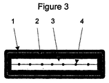
- the liner is then formed into a tube as shown in Fig. 3. It may then be folded into a cruciform shape. An end elevational view of a folded liner in a pipe 6 prior to application of the pipe is shown in Fig. 4.
- the folded liner is reeled onto a drum and placed inside a pressure vessel, similar to that used for conventional eversion technology, which will be familiar to those skilled in the art.
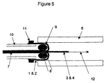
- a length of the tube 7 is pulled out of the pressure vessel, and pushed through an eversion tool 8.
- a part is opened out that is turned inside out to form a "bell" 9 with the adhesive on the outside.
- This is then folded over the outside of the eversion tool and a launch tube 10 on the outlet to the pressure vessel and secured using a clip 11.
- the free end of the release tape 3 is securely attached to a winch cable 12.
- the assembly is then offered to the pipe, whilst maintaining tension on the winch cable 12.
- the assembly is then offered to the pipe, whilst maintaining tension on the winch cable, as shown in Fig. 5.
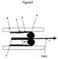
- the liner is pulled into the pipe by the winch using force F (Fig. 6), the eversion tool ensuring that the liner inverts evenly and the exposed surfaces of the adhesive do not come into contact with each other, but are offered evenly to the pipe surface.
- a positive pressure 'P' is applied from the pressure vessel to ensure that all parts of the liner are forced into contact with the pipe wall.
- the tube 7 is installed without removing the means for increasing the surface area of the liner. These enable the liner to "expand" over disconformities in the pipe 6 or to go round bends without the flexible material 1 stretching to within or beyond its predetermined expansion capability, which would otherwise produce a rupture or tendency to rupture, which would lead to leakage.
- the expansion capability of the liner enables the liner to line sharp bends while being adhered to the outside radius of the inner wall of the host pipe, thereby minimising the tendency for air to be trapped behind the liner with consequent reduction in pipe bore.
- the liner 1 goes over pits, can go round even sharp bends, can be installed uninterrupted over long lengths of pipe, and therefore obviates the need for extensive excavation.
- the liner goes over that junction and closes it off. It is a relatively simple matter to puncture the liner in situ by use of a robot which goes along the pipe, guided by TV for visual location of the junction, and which has a device to puncture the liner precisely at the branch pipe, and insert a device if required which holds the edges of the hole in the liner in place.
- Release tape should be sufficiently strong to be pulled the length of the pipe, or collected on to a roller at the connection point with a winch.
- a swab can be attached to the winch so that the pipe is re-cleaned immediately prior to a bonding process and/or primed to enhance adhesion.
- the installation is controlled by controlling the pull-through speed of the winch, and the eversion pressure.
- the system comprises:
- the system will allow lining of rough and irregular internal pipe surfaces and will be capable of lining around multiple bends.
- the system will allow connections to the host pipe to be reestablished through the lining material without the need for access to the outside of the pipe in the vicinity of the connection, whilst retaining the ability to seal unwanted holes in the pipe.
Abstract
Description
- A means of towing the adhered support through the host pipe at a controlled speed, consistent with the capacity of the pressurised fluid supply.
- A means of supplying fluid into the everted section of the liner at a controlled pressure, and at a rate consistent with the speed of the towing system.
- Optionally a means of anchoring the trailing end of the liner to be everted such that it does not tend to accelerate beyond the speed of the towing line, under the influence of the fluid pressure when the length of un-everted liner is small towards the end of the lining run.
- The internal surfaces through which the folded liner is fed must be arranged to maintain any pattern of dimples or corrugations in the liner as it passes through.
- The friction between the internal surfaces of the tool and the liner must exceed that between the external surfaces of the tool and the liner by a margin sufficient to ensure that the tool, which will be otherwise unsupported, is carried along the lined pipe, remaining at all times adjacent to the point of eversion.
- The tool must be capable of passing any obstructions or constrictions in the host pipe.
Claims (31)
- A liner for a pipe, comprising a flexible material (1), the material being formed into a tube having an outer surface and an inner surface, characterised in that the liner comprises means adapted to increase the surface area of the material, the means comprising a profile applied to the outer surface of the tube, and an adhesive (2) applied to the inner surface of the tube.
- A liner according to Claim 1, characterised in that the applied profile comprises corrugations, dimpling, reticulations, waves or the like.
- A liner according to Claim 2, characterised in that the applied profile permits a desired predetermined increase in length and/or bore of the tube.
- A liner according to any preceding claim, characterised in that the adhesive (2) comprises a layer of non-setting adhesive to which the material (1) is bonded.
- A liner according to Claim 4, characterised by a release tape (3) protecting an exposed surface of the adhesive (2).
- A liner according to Claim 5, characterised by the release tape (3) being reinforced in a direction axially of the tube.
- A liner according to any preceding claim, characterised by the material (1) comprising a sheet material.
- A liner according to any of Claim 7, characterised in that the liner comprises a polymeric material, such as polyethylene or polypropylene.
- A liner according to Claim 8 characterised in that the polymeric material is cross-linked.
- A liner according to any preceding claim, characterised in that the liner comprises a material approved for use in contact with potable water.
- A liner according to any preceding claim, characterised in that the material (1) is formed into a tube by folding and securing opposite edges together.
- A liner according to Claim 11, characterised in that the tube is folded whereby its greatest lateral dimension is less than the diameter of the tube.
- A liner according to Claim 12, characterised in that the tube is formed to a cruciform shape and then flattened.
- A liner according to any preceding claim, characterised in that the adhesive (2) comprises a butyl rubber.
- A liner according to any preceding claim, characterised in that the applied profile is formed in the material (1) by heated profiled rollers or by gas jets.
- A method of relining an existing pipeline, comprising everting a liner inside a pipe (6), the liner comprising a flexible material (1) formed into a tube having an outer surface and an inner surface, characterised by the liner having means adapted to increase the surface area thereof after the eversion process has taken place, said means comprising a profile applied to the outer surface of the tube, and adhering the liner to the pipe (6), an adhesive (2) being applied to the inner surface of the tube.
- A method according to Claim 16, characterised by the applied profile comprising corrugations, dimpling, reticulations, waves, or the like.
- A method according to any of Claims 16 to 17, characterised by the means comprising elastomeric properties of the flexible material (1).
- A method according to any of Claims 16 to 18, characterised by the applied profile permitting a desired predetermined increase in length and/or bore of the tube.
- A method according to any of Claims 16 to 19, characterised in that the adhesive (2) comprises a layer of non-setting adhesive to which the flexible material (1) is bonded.
- A method according to any of Claims 16 to 20, characterised in that the liner comprises a release tape (3) protecting an exposed surface of the adhesive (2).
- A method according to Claim 21, characterised in that the release tape (3) is reinforced in a direction axially of the tube.
- A method according to any of Claims 16 to 22, characterised in that the liner comprises metal.
- A method according to any of Claims 16 to 22, characterised in that the liner comprises a polymeric material such as thermoplastic elastomer or theroplastic polyurethane.
- A method according to Claim 24, characterised in that the liner comprises a polymeric material which is cross linked.
- A method according to any of Claims 16 to 25, characterised in that the liner comprises materials approved for use in contact with potable water.
- A method according to any of Claims 16 to 26, characterised in that the liner is folded whereby its greatest lateral dimension is less than the diameter of the tube.
- A method according to Claim 27, characterised in that the tube is formed to a cruciform shape and then flattened.
- A method according to any of Claims 16 to 28, characterised in that the adhesive (2) or sealant comprises a material, a major component of which is a butyl rubber.
- A pipe, characterised by being lined with a liner according to any of Claims 1 to 15, or by a method according to any of Claims 16 to 29.
- A pipe according to Claim 30, characterised by a pipe junction and by having a fluid take off through the liner at the junction.
Applications Claiming Priority (5)
| Application Number | Priority Date | Filing Date | Title |
|---|---|---|---|
| GBGB9805801.9A GB9805801D0 (en) | 1998-03-18 | 1998-03-18 | A liner |
| GB9805801 | 1998-03-18 | ||
| GB9828053 | 1998-12-18 | ||
| GBGB9828053.0A GB9828053D0 (en) | 1998-12-18 | 1998-12-18 | A liner |
| PCT/GB1999/000851 WO1999047340A1 (en) | 1998-03-18 | 1999-03-18 | Liner and method for lining a pipeline |
Publications (2)
| Publication Number | Publication Date |
|---|---|
| EP1064143A1 EP1064143A1 (en) | 2001-01-03 |
| EP1064143B1 true EP1064143B1 (en) | 2003-02-26 |
Family
ID=26313303
Family Applications (1)
| Application Number | Title | Priority Date | Filing Date |
|---|---|---|---|
| EP99910542A Expired - Lifetime EP1064143B1 (en) | 1998-03-18 | 1999-03-18 | Liner and method for lining a pipeline |
Country Status (7)
| Country | Link |
|---|---|
| US (1) | US6446670B1 (en) |
| EP (1) | EP1064143B1 (en) |
| AT (1) | ATE233168T1 (en) |
| AU (1) | AU755196B2 (en) |
| CA (1) | CA2324307A1 (en) |
| DE (1) | DE69905552D1 (en) |
| WO (1) | WO1999047340A1 (en) |
Families Citing this family (19)
| Publication number | Priority date | Publication date | Assignee | Title |
|---|---|---|---|---|
| CN1437675A (en) * | 2000-05-16 | 2003-08-20 | 索德科技有限公司 | Apparatus for and method of lining passageways |
| AU2003232519A1 (en) * | 2002-06-18 | 2003-12-31 | Sideliner Enterprises Pty Ltd | Guiding means for installation of formed-in-situ conduit repairs |
| US7292156B2 (en) * | 2003-10-07 | 2007-11-06 | Underground Solutions Technologies Group, Inc. | Remote tapping method and system for internally tapping a conduit |
| US20060189754A1 (en) * | 2005-02-18 | 2006-08-24 | Serhatkulu Toprak F | Method of making a composition |
| US7946349B2 (en) * | 2006-07-13 | 2011-05-24 | Shell Oil Company | Method of radially expanding a tubular element |
| BRPI0718832A2 (en) * | 2006-11-21 | 2014-02-04 | Shell Int Research | METHOD OF RADIALLY EXPANDING A TUBULAR ELEMENT |
| GB2456711B (en) | 2006-11-22 | 2011-08-31 | Shell Int Research | Method of imaging of seismic data involving a virtual source and of producing a hydrocarbon fluid |
| CA2700952A1 (en) | 2007-10-29 | 2009-05-07 | Shell Internationale Research Maatschappij B.V. | Method of radially expanding a tubular element |
| BRPI0819291A2 (en) * | 2007-11-22 | 2015-05-26 | Shell Int Research | Method for radially expanding a tubular element. |
| CA2706279C (en) * | 2007-12-13 | 2016-05-17 | Shell Internationale Research Maatschappij B.V. | Method of expanding a tubular element in a wellbore |
| WO2009087068A2 (en) * | 2008-01-04 | 2009-07-16 | Shell Internationale Research Maatschappij B.V. | Method of expanding a tubular element in a wellbore |
| CN101910554B (en) | 2008-01-04 | 2013-12-11 | 国际壳牌研究有限公司 | Method of drilling a wellbore |
| WO2011070353A2 (en) | 2009-12-07 | 2011-06-16 | Smart Pipe Company, Lp | Systems and methods for making pipe, and method of installing the pipe in a pipeline |
| EP2460972A1 (en) | 2010-12-03 | 2012-06-06 | Shell Internationale Research Maatschappij B.V. | Method and system for radially expanding a tubular element |
| WO2013004610A1 (en) | 2011-07-07 | 2013-01-10 | Shell Internationale Research Maatschappij B.V. | Method and system of radially expanding a tubular element in a wellbore |
| FR3014528B1 (en) * | 2013-12-10 | 2016-02-26 | Itp Sa | METHOD AND DEVICE FOR INSTALLING A DUAL ENVELOPE DUCT |
| US10309575B2 (en) | 2017-04-12 | 2019-06-04 | Inner Cure Technologies | Underground pipe repair device with radial annular spacers and related systems and methods |
| US11173634B2 (en) | 2018-02-01 | 2021-11-16 | Ina Acquisition Corp | Electromagnetic radiation curable pipe liner and method of making and installing the same |
| US10704728B2 (en) | 2018-03-20 | 2020-07-07 | Ina Acquisition Corp. | Pipe liner and method of making same |
Family Cites Families (7)
| Publication number | Priority date | Publication date | Assignee | Title |
|---|---|---|---|---|
| JPS59194809A (en) * | 1983-04-18 | 1984-11-05 | Tokyo Gas Co Ltd | Lining material of pipe line having bent pipe |
| US4576285A (en) * | 1983-05-20 | 1986-03-18 | Fres-Co System Usa, Inc. | Sealed flexible container with non-destructive peelable opening and apparatus and method for forming same |
| GB8718212D0 (en) * | 1987-07-31 | 1987-09-09 | Angus Fire Armour Ltd | Lining tubular objects |
| JPH06249363A (en) * | 1993-03-02 | 1994-09-06 | Osaka Gas Co Ltd | Internal insertion connection pipe device |
| US5501248A (en) * | 1994-06-23 | 1996-03-26 | Lmk Enterprises, Inc. | Expandable pipe liner and method of installing same |
| DK171387B1 (en) * | 1994-10-17 | 1996-10-07 | Loegstoer Roer A S | Shrink |
| US6129119A (en) * | 1998-09-11 | 2000-10-10 | Karl Weiss Hoch - Tief - Und Rohrleitungsbau Gmbh & Co. | Flexible tube for lining pipes and ducts as well as method and an apparatus for manufacturing thereof |
-
1999
- 1999-03-18 EP EP99910542A patent/EP1064143B1/en not_active Expired - Lifetime
- 1999-03-18 DE DE69905552T patent/DE69905552D1/en not_active Expired - Lifetime
- 1999-03-18 CA CA002324307A patent/CA2324307A1/en not_active Abandoned
- 1999-03-18 WO PCT/GB1999/000851 patent/WO1999047340A1/en active IP Right Grant
- 1999-03-18 AT AT99910542T patent/ATE233168T1/en not_active IP Right Cessation
- 1999-03-18 AU AU29474/99A patent/AU755196B2/en not_active Ceased
- 1999-03-18 US US09/646,697 patent/US6446670B1/en not_active Expired - Fee Related
Also Published As
| Publication number | Publication date |
|---|---|
| US6446670B1 (en) | 2002-09-10 |
| AU2947499A (en) | 1999-10-11 |
| EP1064143A1 (en) | 2001-01-03 |
| WO1999047340A1 (en) | 1999-09-23 |
| ATE233168T1 (en) | 2003-03-15 |
| AU755196B2 (en) | 2002-12-05 |
| CA2324307A1 (en) | 1999-09-23 |
| DE69905552D1 (en) | 2003-04-03 |
Similar Documents
| Publication | Publication Date | Title |
|---|---|---|
| EP1064143B1 (en) | Liner and method for lining a pipeline | |
| US7896032B2 (en) | Method and device for lining pipe | |
| US5855729A (en) | Apparatus for providing a tubular material within a pipeline | |
| US5778938A (en) | Method of installation of dual containment pipe rehabilitation system | |
| US5501248A (en) | Expandable pipe liner and method of installing same | |
| US5736166A (en) | Flow-through apparatus for lining of pipelines | |
| US5213727A (en) | Method for installing a pipe liner | |
| US6612340B1 (en) | Turnback protection for installation of cured in place liners | |
| EP0517489A1 (en) | Method and apparatus for installing a pipe liner | |
| WO1997035707A1 (en) | Method for lining of lateral pipelines with flow-through apparatus | |
| EP0859929A1 (en) | Method and apparatus for lining a conduit | |
| JP2011132992A (en) | Water stop packer | |
| JPH01307597A (en) | Line pipe with laminated lining including adhesive layer and installation thereof | |
| US20040020544A1 (en) | Pressure bag and method of lining branch pipe | |
| AU4605799A (en) | Method for installing at least one pipe line and/or an empty conduit in supply and sanitation pipes which have already been laid, especially in sewer pipe systems or networks and similar | |
| EP0101712B1 (en) | A lining hose for restoring or making a conveyor channel | |
| JP4636752B2 (en) | Rehabilitation pipe water stop method and water stop member holding device | |
| EP0787940A1 (en) | Methods of and arrangements for lining pipes | |
| EP0875710A1 (en) | An end termination for pipes | |
| EP1390658B1 (en) | Method and device for laying a separate channel inside a fluid carrying duct | |
| WO2018000542A1 (en) | Unmanned shipborne pipeline maintenance unit | |
| MXPA01006726A (en) | A pipe liner, a liner product and methods for forming and installing the liner. | |
| JP3660400B2 (en) | Pipe branch repair method and repair device | |
| RU2172446C1 (en) | Device for local lining of internal surface of pipe line | |
| NL9001624A (en) | Thermoplastic saddle for repairing pipeline with branch - having telescopic branch part enabling transportation through pipeline to branch |
Legal Events
| Date | Code | Title | Description |
|---|---|---|---|
| PUAI | Public reference made under article 153(3) epc to a published international application that has entered the european phase |
Free format text: ORIGINAL CODE: 0009012 |
|
| 17P | Request for examination filed |
Effective date: 20001017 |
|
| AK | Designated contracting states |
Kind code of ref document: A1 Designated state(s): AT BE CH CY DE DK ES FI FR GB GR IE IT LI LU MC NL PT SE |
|
| 17Q | First examination report despatched |
Effective date: 20010209 |
|
| GRAG | Despatch of communication of intention to grant |
Free format text: ORIGINAL CODE: EPIDOS AGRA |
|
| GRAG | Despatch of communication of intention to grant |
Free format text: ORIGINAL CODE: EPIDOS AGRA |
|
| GRAH | Despatch of communication of intention to grant a patent |
Free format text: ORIGINAL CODE: EPIDOS IGRA |
|
| GRAH | Despatch of communication of intention to grant a patent |
Free format text: ORIGINAL CODE: EPIDOS IGRA |
|
| GRAA | (expected) grant |
Free format text: ORIGINAL CODE: 0009210 |
|
| AK | Designated contracting states |
Designated state(s): AT BE CH CY DE DK ES FI FR GB GR IE IT LI LU MC NL PT SE |
|
| PG25 | Lapsed in a contracting state [announced via postgrant information from national office to epo] |
Ref country code: NL Free format text: LAPSE BECAUSE OF FAILURE TO SUBMIT A TRANSLATION OF THE DESCRIPTION OR TO PAY THE FEE WITHIN THE PRESCRIBED TIME-LIMIT Effective date: 20030226 Ref country code: LI Free format text: LAPSE BECAUSE OF FAILURE TO SUBMIT A TRANSLATION OF THE DESCRIPTION OR TO PAY THE FEE WITHIN THE PRESCRIBED TIME-LIMIT Effective date: 20030226 Ref country code: IT Free format text: LAPSE BECAUSE OF FAILURE TO SUBMIT A TRANSLATION OF THE DESCRIPTION OR TO PAY THE FEE WITHIN THE PRESCRIBED TIME-LIMIT;WARNING: LAPSES OF ITALIAN PATENTS WITH EFFECTIVE DATE BEFORE 2007 MAY HAVE OCCURRED AT ANY TIME BEFORE 2007. THE CORRECT EFFECTIVE DATE MAY BE DIFFERENT FROM THE ONE RECORDED. Effective date: 20030226 Ref country code: GR Free format text: LAPSE BECAUSE OF FAILURE TO SUBMIT A TRANSLATION OF THE DESCRIPTION OR TO PAY THE FEE WITHIN THE PRESCRIBED TIME-LIMIT Effective date: 20030226 Ref country code: FR Free format text: LAPSE BECAUSE OF NON-PAYMENT OF DUE FEES Effective date: 20030226 Ref country code: FI Free format text: LAPSE BECAUSE OF FAILURE TO SUBMIT A TRANSLATION OF THE DESCRIPTION OR TO PAY THE FEE WITHIN THE PRESCRIBED TIME-LIMIT Effective date: 20030226 Ref country code: CH Free format text: LAPSE BECAUSE OF FAILURE TO SUBMIT A TRANSLATION OF THE DESCRIPTION OR TO PAY THE FEE WITHIN THE PRESCRIBED TIME-LIMIT Effective date: 20030226 Ref country code: BE Free format text: LAPSE BECAUSE OF FAILURE TO SUBMIT A TRANSLATION OF THE DESCRIPTION OR TO PAY THE FEE WITHIN THE PRESCRIBED TIME-LIMIT Effective date: 20030226 Ref country code: AT Free format text: LAPSE BECAUSE OF FAILURE TO SUBMIT A TRANSLATION OF THE DESCRIPTION OR TO PAY THE FEE WITHIN THE PRESCRIBED TIME-LIMIT Effective date: 20030226 |
|
| PGFP | Annual fee paid to national office [announced via postgrant information from national office to epo] |
Ref country code: IE Payment date: 20030226 Year of fee payment: 5 |
|
| REG | Reference to a national code |
Ref country code: GB Ref legal event code: FG4D |
|
| REG | Reference to a national code |
Ref country code: CH Ref legal event code: EP |
|
| PGFP | Annual fee paid to national office [announced via postgrant information from national office to epo] |
Ref country code: FR Payment date: 20030310 Year of fee payment: 5 |
|
| PGFP | Annual fee paid to national office [announced via postgrant information from national office to epo] |
Ref country code: GB Payment date: 20030312 Year of fee payment: 5 Ref country code: AT Payment date: 20030312 Year of fee payment: 5 |
|
| PGFP | Annual fee paid to national office [announced via postgrant information from national office to epo] |
Ref country code: FI Payment date: 20030313 Year of fee payment: 5 |
|
| PG25 | Lapsed in a contracting state [announced via postgrant information from national office to epo] |
Ref country code: CY Free format text: LAPSE BECAUSE OF FAILURE TO SUBMIT A TRANSLATION OF THE DESCRIPTION OR TO PAY THE FEE WITHIN THE PRESCRIBED TIME-LIMIT Effective date: 20030318 |
|
| PGFP | Annual fee paid to national office [announced via postgrant information from national office to epo] |
Ref country code: DK Payment date: 20030318 Year of fee payment: 5 |
|
| PGFP | Annual fee paid to national office [announced via postgrant information from national office to epo] |
Ref country code: NL Payment date: 20030327 Year of fee payment: 5 Ref country code: GR Payment date: 20030327 Year of fee payment: 5 Ref country code: DE Payment date: 20030327 Year of fee payment: 5 |
|
| PGFP | Annual fee paid to national office [announced via postgrant information from national office to epo] |
Ref country code: LU Payment date: 20030328 Year of fee payment: 5 |
|
| PGFP | Annual fee paid to national office [announced via postgrant information from national office to epo] |
Ref country code: MC Payment date: 20030331 Year of fee payment: 5 Ref country code: CH Payment date: 20030331 Year of fee payment: 5 |
|
| REG | Reference to a national code |
Ref country code: IE Ref legal event code: FG4D |
|
| REF | Corresponds to: |
Ref document number: 69905552 Country of ref document: DE Date of ref document: 20030403 Kind code of ref document: P |
|
| PGFP | Annual fee paid to national office [announced via postgrant information from national office to epo] |
Ref country code: ES Payment date: 20030409 Year of fee payment: 5 |
|
| PGFP | Annual fee paid to national office [announced via postgrant information from national office to epo] |
Ref country code: BE Payment date: 20030522 Year of fee payment: 5 |
|
| PG25 | Lapsed in a contracting state [announced via postgrant information from national office to epo] |
Ref country code: SE Free format text: LAPSE BECAUSE OF FAILURE TO SUBMIT A TRANSLATION OF THE DESCRIPTION OR TO PAY THE FEE WITHIN THE PRESCRIBED TIME-LIMIT Effective date: 20030526 Ref country code: PT Free format text: LAPSE BECAUSE OF FAILURE TO SUBMIT A TRANSLATION OF THE DESCRIPTION OR TO PAY THE FEE WITHIN THE PRESCRIBED TIME-LIMIT Effective date: 20030526 Ref country code: DK Free format text: LAPSE BECAUSE OF FAILURE TO SUBMIT A TRANSLATION OF THE DESCRIPTION OR TO PAY THE FEE WITHIN THE PRESCRIBED TIME-LIMIT Effective date: 20030526 |
|
| PG25 | Lapsed in a contracting state [announced via postgrant information from national office to epo] |
Ref country code: DE Free format text: LAPSE BECAUSE OF FAILURE TO SUBMIT A TRANSLATION OF THE DESCRIPTION OR TO PAY THE FEE WITHIN THE PRESCRIBED TIME-LIMIT Effective date: 20030527 |
|
| NLV1 | Nl: lapsed or annulled due to failure to fulfill the requirements of art. 29p and 29m of the patents act | ||
| PG25 | Lapsed in a contracting state [announced via postgrant information from national office to epo] |
Ref country code: ES Free format text: LAPSE BECAUSE OF FAILURE TO SUBMIT A TRANSLATION OF THE DESCRIPTION OR TO PAY THE FEE WITHIN THE PRESCRIBED TIME-LIMIT Effective date: 20030828 |
|
| PLBE | No opposition filed within time limit |
Free format text: ORIGINAL CODE: 0009261 |
|
| STAA | Information on the status of an ep patent application or granted ep patent |
Free format text: STATUS: NO OPPOSITION FILED WITHIN TIME LIMIT |
|
| EN | Fr: translation not filed | ||
| 26N | No opposition filed |
Effective date: 20031127 |
|
| PG25 | Lapsed in a contracting state [announced via postgrant information from national office to epo] |
Ref country code: LU Free format text: LAPSE BECAUSE OF NON-PAYMENT OF DUE FEES Effective date: 20040318 Ref country code: IE Free format text: LAPSE BECAUSE OF NON-PAYMENT OF DUE FEES Effective date: 20040318 Ref country code: GB Free format text: LAPSE BECAUSE OF NON-PAYMENT OF DUE FEES Effective date: 20040318 |
|
| PG25 | Lapsed in a contracting state [announced via postgrant information from national office to epo] |
Ref country code: MC Free format text: LAPSE BECAUSE OF NON-PAYMENT OF DUE FEES Effective date: 20040331 |
|
| GBPC | Gb: european patent ceased through non-payment of renewal fee |
Effective date: 20040318 |
|
| REG | Reference to a national code |
Ref country code: IE Ref legal event code: MM4A |