EP1063437A2 - Axial force controlling method and bearing apparatus - Google Patents
Axial force controlling method and bearing apparatus Download PDFInfo
- Publication number
- EP1063437A2 EP1063437A2 EP00109930A EP00109930A EP1063437A2 EP 1063437 A2 EP1063437 A2 EP 1063437A2 EP 00109930 A EP00109930 A EP 00109930A EP 00109930 A EP00109930 A EP 00109930A EP 1063437 A2 EP1063437 A2 EP 1063437A2
- Authority
- EP
- European Patent Office
- Prior art keywords
- axial force
- caulked
- rolling bearing
- shaft body
- cylindrical portion
- Prior art date
- Legal status (The legal status is an assumption and is not a legal conclusion. Google has not performed a legal analysis and makes no representation as to the accuracy of the status listed.)
- Granted
Links
- 238000000034 method Methods 0.000 title claims abstract description 27
- 230000002093 peripheral effect Effects 0.000 claims abstract description 8
- 238000005452 bending Methods 0.000 claims abstract description 5
- 238000005096 rolling process Methods 0.000 claims description 47
- 235000019589 hardness Nutrition 0.000 description 40
- 238000005259 measurement Methods 0.000 description 19
- 238000002474 experimental method Methods 0.000 description 2
- 238000012986 modification Methods 0.000 description 2
- 230000004048 modification Effects 0.000 description 2
- 238000010586 diagram Methods 0.000 description 1
- 238000010438 heat treatment Methods 0.000 description 1
- 230000036316 preload Effects 0.000 description 1
Images


Classifications
-
- F—MECHANICAL ENGINEERING; LIGHTING; HEATING; WEAPONS; BLASTING
- F16—ENGINEERING ELEMENTS AND UNITS; GENERAL MEASURES FOR PRODUCING AND MAINTAINING EFFECTIVE FUNCTIONING OF MACHINES OR INSTALLATIONS; THERMAL INSULATION IN GENERAL
- F16C—SHAFTS; FLEXIBLE SHAFTS; ELEMENTS OR CRANKSHAFT MECHANISMS; ROTARY BODIES OTHER THAN GEARING ELEMENTS; BEARINGS
- F16C43/00—Assembling bearings
- F16C43/04—Assembling rolling-contact bearings
-
- B—PERFORMING OPERATIONS; TRANSPORTING
- B60—VEHICLES IN GENERAL
- B60B—VEHICLE WHEELS; CASTORS; AXLES FOR WHEELS OR CASTORS; INCREASING WHEEL ADHESION
- B60B27/00—Hubs
-
- B—PERFORMING OPERATIONS; TRANSPORTING
- B60—VEHICLES IN GENERAL
- B60B—VEHICLE WHEELS; CASTORS; AXLES FOR WHEELS OR CASTORS; INCREASING WHEEL ADHESION
- B60B27/00—Hubs
- B60B27/0078—Hubs characterised by the fixation of bearings
- B60B27/0084—Hubs characterised by the fixation of bearings caulking to fix inner race
-
- F—MECHANICAL ENGINEERING; LIGHTING; HEATING; WEAPONS; BLASTING
- F16—ENGINEERING ELEMENTS AND UNITS; GENERAL MEASURES FOR PRODUCING AND MAINTAINING EFFECTIVE FUNCTIONING OF MACHINES OR INSTALLATIONS; THERMAL INSULATION IN GENERAL
- F16C—SHAFTS; FLEXIBLE SHAFTS; ELEMENTS OR CRANKSHAFT MECHANISMS; ROTARY BODIES OTHER THAN GEARING ELEMENTS; BEARINGS
- F16C19/00—Bearings with rolling contact, for exclusively rotary movement
- F16C19/02—Bearings with rolling contact, for exclusively rotary movement with bearing balls essentially of the same size in one or more circular rows
- F16C19/14—Bearings with rolling contact, for exclusively rotary movement with bearing balls essentially of the same size in one or more circular rows for both radial and axial load
- F16C19/18—Bearings with rolling contact, for exclusively rotary movement with bearing balls essentially of the same size in one or more circular rows for both radial and axial load with two or more rows of balls
- F16C19/181—Bearings with rolling contact, for exclusively rotary movement with bearing balls essentially of the same size in one or more circular rows for both radial and axial load with two or more rows of balls with angular contact
- F16C19/183—Bearings with rolling contact, for exclusively rotary movement with bearing balls essentially of the same size in one or more circular rows for both radial and axial load with two or more rows of balls with angular contact with two rows at opposite angles
- F16C19/184—Bearings with rolling contact, for exclusively rotary movement with bearing balls essentially of the same size in one or more circular rows for both radial and axial load with two or more rows of balls with angular contact with two rows at opposite angles in O-arrangement
- F16C19/186—Bearings with rolling contact, for exclusively rotary movement with bearing balls essentially of the same size in one or more circular rows for both radial and axial load with two or more rows of balls with angular contact with two rows at opposite angles in O-arrangement with three raceways provided integrally on parts other than race rings, e.g. third generation hubs
-
- F—MECHANICAL ENGINEERING; LIGHTING; HEATING; WEAPONS; BLASTING
- F16—ENGINEERING ELEMENTS AND UNITS; GENERAL MEASURES FOR PRODUCING AND MAINTAINING EFFECTIVE FUNCTIONING OF MACHINES OR INSTALLATIONS; THERMAL INSULATION IN GENERAL
- F16C—SHAFTS; FLEXIBLE SHAFTS; ELEMENTS OR CRANKSHAFT MECHANISMS; ROTARY BODIES OTHER THAN GEARING ELEMENTS; BEARINGS
- F16C2240/00—Specified values or numerical ranges of parameters; Relations between them
- F16C2240/40—Linear dimensions, e.g. length, radius, thickness, gap
-
- F—MECHANICAL ENGINEERING; LIGHTING; HEATING; WEAPONS; BLASTING
- F16—ENGINEERING ELEMENTS AND UNITS; GENERAL MEASURES FOR PRODUCING AND MAINTAINING EFFECTIVE FUNCTIONING OF MACHINES OR INSTALLATIONS; THERMAL INSULATION IN GENERAL
- F16C—SHAFTS; FLEXIBLE SHAFTS; ELEMENTS OR CRANKSHAFT MECHANISMS; ROTARY BODIES OTHER THAN GEARING ELEMENTS; BEARINGS
- F16C2326/00—Articles relating to transporting
- F16C2326/01—Parts of vehicles in general
- F16C2326/02—Wheel hubs or castors
-
- Y—GENERAL TAGGING OF NEW TECHNOLOGICAL DEVELOPMENTS; GENERAL TAGGING OF CROSS-SECTIONAL TECHNOLOGIES SPANNING OVER SEVERAL SECTIONS OF THE IPC; TECHNICAL SUBJECTS COVERED BY FORMER USPC CROSS-REFERENCE ART COLLECTIONS [XRACs] AND DIGESTS
- Y10—TECHNICAL SUBJECTS COVERED BY FORMER USPC
- Y10T—TECHNICAL SUBJECTS COVERED BY FORMER US CLASSIFICATION
- Y10T29/00—Metal working
- Y10T29/49—Method of mechanical manufacture
- Y10T29/49481—Wheel making
- Y10T29/49492—Land wheel
- Y10T29/49533—Hub making
- Y10T29/49535—Hub making with assembling
-
- Y—GENERAL TAGGING OF NEW TECHNOLOGICAL DEVELOPMENTS; GENERAL TAGGING OF CROSS-SECTIONAL TECHNOLOGIES SPANNING OVER SEVERAL SECTIONS OF THE IPC; TECHNICAL SUBJECTS COVERED BY FORMER USPC CROSS-REFERENCE ART COLLECTIONS [XRACs] AND DIGESTS
- Y10—TECHNICAL SUBJECTS COVERED BY FORMER USPC
- Y10T—TECHNICAL SUBJECTS COVERED BY FORMER US CLASSIFICATION
- Y10T29/00—Metal working
- Y10T29/49—Method of mechanical manufacture
- Y10T29/49481—Wheel making
- Y10T29/49492—Land wheel
- Y10T29/49533—Hub making
- Y10T29/49536—Hub shaping
-
- Y—GENERAL TAGGING OF NEW TECHNOLOGICAL DEVELOPMENTS; GENERAL TAGGING OF CROSS-SECTIONAL TECHNOLOGIES SPANNING OVER SEVERAL SECTIONS OF THE IPC; TECHNICAL SUBJECTS COVERED BY FORMER USPC CROSS-REFERENCE ART COLLECTIONS [XRACs] AND DIGESTS
- Y10—TECHNICAL SUBJECTS COVERED BY FORMER USPC
- Y10T—TECHNICAL SUBJECTS COVERED BY FORMER US CLASSIFICATION
- Y10T29/00—Metal working
- Y10T29/49—Method of mechanical manufacture
- Y10T29/49636—Process for making bearing or component thereof
- Y10T29/49643—Rotary bearing
- Y10T29/49679—Anti-friction bearing or component thereof
- Y10T29/49682—Assembling of race and rolling anti-friction members
-
- Y—GENERAL TAGGING OF NEW TECHNOLOGICAL DEVELOPMENTS; GENERAL TAGGING OF CROSS-SECTIONAL TECHNOLOGIES SPANNING OVER SEVERAL SECTIONS OF THE IPC; TECHNICAL SUBJECTS COVERED BY FORMER USPC CROSS-REFERENCE ART COLLECTIONS [XRACs] AND DIGESTS
- Y10—TECHNICAL SUBJECTS COVERED BY FORMER USPC
- Y10T—TECHNICAL SUBJECTS COVERED BY FORMER US CLASSIFICATION
- Y10T29/00—Metal working
- Y10T29/49—Method of mechanical manufacture
- Y10T29/49636—Process for making bearing or component thereof
- Y10T29/49696—Mounting
-
- Y—GENERAL TAGGING OF NEW TECHNOLOGICAL DEVELOPMENTS; GENERAL TAGGING OF CROSS-SECTIONAL TECHNOLOGIES SPANNING OVER SEVERAL SECTIONS OF THE IPC; TECHNICAL SUBJECTS COVERED BY FORMER USPC CROSS-REFERENCE ART COLLECTIONS [XRACs] AND DIGESTS
- Y10—TECHNICAL SUBJECTS COVERED BY FORMER USPC
- Y10T—TECHNICAL SUBJECTS COVERED BY FORMER US CLASSIFICATION
- Y10T29/00—Metal working
- Y10T29/49—Method of mechanical manufacture
- Y10T29/49636—Process for making bearing or component thereof
- Y10T29/497—Pre-usage process, e.g., preloading, aligning
Definitions
- the present invention relates to an axial force controlling method for controlling an axial force applied to a rolling bearing in a bearing apparatus having a shaft body, the rolling bearing being mounted to the shaft body such that the rolling bearing fits an outside of the shaft body, and the bearing apparatus.
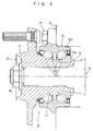
- a bearing apparatus shown in FIG. 5 is a hub unit for a driving wheel of a vehicle.
- the hub unit has a hub wheel 10 as a shaft body and an angular ball bearing 12 which is mounted to a shaft portion 11 of the hub wheel 10 such that the ball bearing 12 fits an outside of the shaft portion 11 and which is an example of a rolling bearing of an inclined contact type.
- a free end of the shaft portion 11 is caused to bulge and deformed outward in a diameter direction by rolling caulking to form a caulked portion 13.
- the bearing 12 has an inner ring 12a, an outer ring 12b, a plurality of balls 12c, and two snap cages 12d. In the bearing 12, necessary preload is applied to the inner ring 12a by the caulked portion 13 and the bearing 12 is prevented from dropping off from the hub wheel 10.
- Such a hub unit is mounted between a drive shaft 14 and a shaft case 15 of the vehicle.
- the shaft portion 11 of the hub wheel 10 is spline-fitted with the drive shaft 14 and connected to the drive shaft 14 by a nut 16 and an outer ring 12b of the bearing 12 is connected to the shaft case 15 by a bolt 17.
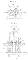
- a caulking jig 20 as shown in FIG. 7 is held against a cylindrical portion 11a to be caulked on a free end side of the shaft portion 11 as shown by a phantom line in FIG. 6 before caulking. Then, by rolling the caulking jig 20 about a one-dot dashed line O at a constant angle ⁇ , the cylindrical portion 11a to be caulked is caused to bulge and deformed radially outward, thereby forming the caulked portion 13 held against an outer end face of the inner ring 12a.
- the axial force is controlled by merely caulking the caulked portion 13 firmly, adjusting a thickness of the caulked portion 13, or adjusting applied pressure in caulking.
- the present inventors have studied the axial force earnestly and as a result, found the following point.
- the method comprises the following steps for controlling the axial force applied to the roiling bearing through the caulked portion: a first step of setting a position (first position) of an end edge on an inner periphery side of a chamfered portion formed at an inner peripheral shoulder portion of the inner ring; and a second step of setting a relationship between relative positions on an axial direction of the first position and a position (second position) of a caulking starting point on an inner periphery side of the cylindrical portion to be
- the second step is a step of positioning the second position on an axially outside with respect to the first position.
- the second step is a step of axially aligning the second position with respect to the first position.
- the second step is a step of positioning the second position on an axially inside with respect to the first position.
- the method includes a third step of setting a radial thickness of the cylindrical portion to be caulked.
- the method includes a fourth step of setting a hardness of the cylindrical portion to be caulked.
- a bearing apparatus of the present invention comprises a rolling bearing and a shaft body, the rolling bearing being mounted to the shaft body such that the rolling bearing fits an outside of the shaft body and the shaft body having a cylindrical portion to be caulked on a free end side of the shaft body, wherein the cylindrical portion to be caulked of the shaft body is bent outward in a diameter direction onto an outer end face of an inner ring to form a caulked portion in a state in which a relationship between relative positions in an axial direction of a caulking starting point on an inner periphery side of the cylindrical portion and an end edge on an inner periphery side of a chamfered portion formed at an inner peripheral shoulder portion of the inner ring of the rolling bearing, and an axial force is applied to the rolling bearing through the caulked portion.
- a hub unit for a vehicle driving wheel is taken as an example of the bearing apparatus. Because a basic structure of the hub unit is shown in FIG. 5, a detailed description of it will be omitted.
- FIGS. 1 to 3 show a state before bending and caulking a cylindrical portion 11a to be caulked of a shaft portion 11 outward in a diameter direction onto an outer end face of an inner ring 12a. Illustration of a form after the caulking is omitted.
- a character A designates a position on an axial direction of an end edge on an inner periphery side at a chamfered portion at an inner peripheral shoulder portion of the inner ring 12a of a rolling bearing 12 as a first position. In the following description, this position will be referred to as an origin point position A.
- a character B designates a position of a caulking starting point on an inner periphery side of the cylindrical portion 11a to be caulked as a second position.
- the axial force controlling method of this embodiment includes a first step of setting the origin point position A and a second step of setting a relationship between relative positions in an axial direction of the origin point position A and the caulking starting position B as the steps for controlling an axial force applied to the rolling bearing 12 through the caulked portion 13.
- the caulking starting point position B is positioned on an axially outside with respect to the origin point position A in FIG. 1, the caulking starting point position B and the origin point position A are aligned with each other in the axial direction in FIG. 2, and the caulking starting point position A is positioned on an axially inside with respect to the origin point position A in FIG. 3.
- the axial direction is plotted in a one-dimensional coordinate, e.g., x
- the origin point position A is defined as an origin point of the one-dimensional coordinate x
- the caulking starting point position B is defined as a coordinate point x on the one-dimensional coordinate.
- the coordinate point x of the caulking starting point position B is greater than 0 in the case of FIG. 1
- the coordinate point x of the caulking starting point position B is equal to 0 in the case of Fig. 2
- the coordinate point x of the caulking starting point position B is less than 0 in the case of FIG. 3.
- the present inventors measured the axial force according to the settings of the relationship between the relative positions of the origin point position A and the caulking starting point position B in the respective cases of FIGS. 1 to 3 by experiment and obtained results as shown in FIG. 4.
- a horizontal axis designates x/t and a vertical axis designates the axial force (kgf) respectively in FIG. 4.
- hardness of the cylindrical portion 11a to be caulked is varied among the case of FIG. 1, the case of FIG. 2, and the case of FIG. 3 to be low (16 to 18 HRC: hardness 1, represented by a mark ⁇ in FIG. 4), middle (20 to 22 HRC: hardness 2, represented by marks ⁇ and ⁇ in FIG. 4), and high (26 to 28 HRC: hardness 3, represented by a mark ⁇ in FIG. 4).
- the radial thickness t of the cylindrical portion 11a to be caulked is maintained at a constant value, i.e., 5 mm to carry out measurement.
- two kinds of radial thicknesses t of the cylindrical portion 11a to be caulked i.e., 5 mm ( ⁇ in FIG. 4) and 7 mm ( ⁇ in FIG. 4) are used to carry out the measurement.
- the caulking starting point position B As pieced together from the above measurement results, the closer the caulking starting point position B to the origin point position A, the greater the axial force becomes, but the caulking starting position B does not necessarily have to be aligned with the origin point position A if the above-described axial force required to ensure the rolling property of the balls 12c is considered and the caulking starting position B may be separated axially outward or axially inward from the origin point position A. In this case, there are both axially outward and inward maximum permissible separated distances, it is necessary to set the caulking starting point position B within a range of the maximum separated distances to control the axial force.
- the radial thickness of the cylindrical portion 11a to be caulked is also related to the axial force, it is preferable to consider the radial thickness in addition to the axial position of the caulking starting point position B in controlling the axial force.
- the hardness of the cylindrical portion 11a to be caulked is related to the axial force, it is preferable to consider the hardness in addition to the axial position of the caulking starting point position B in controlling the axial force.
- the axial force controlling method of the present embodiment it is possible to easily control the axial force such that the proper axial force can be obtained basically by setting the relationship between the relative positions.
- the bearing apparatus to which the present invention is applied is not limited to the hub wheel shown in the above-described embodiment.
- the invention can be applied to control of the axial force in every bearing apparatus having a rolling bearing and a shaft body, the rolling bearing being mounted to the shaft body such that the rolling bearing fits an outside of the shaft body, the rolling bearing being prevented from dropping off by holding the caulked portion against the outer end face of the inner ring of the rolling bearing, the caulked portion being formed by bending the cylindrical portion to be caulked on the free end side of the shaft body outward in the diameter direction.
- the bearing apparatus has the rolling bearing 12 and the shaft body 11, the rolling bearing 12 being mounted to the shaft body 11 such that the rolling bearing 12 fits the outside of the shaft body 11, and the shaft body 11 having the cylindrical portion 11a to be caulked on the free end side of the shaft body 11.
- the cylindrical portion 11a to be caulked of the shaft body 11 is bent outward in the diameter direction onto the outer end face of the inner ring 12a to form the caulked portion 13 in a state in which the relationship between the relative positions in the axial direction of the caulking starting point position B on the inner periphery side of the cylindrical portion 11a and the position A of the end edge on the inner periphery side of the chamfered portion formed at the inner peripheral shoulder portion of the inner ring of the rolling bearing is set.
- the axial force is applied to the rolling bearing 12 through the caulked portion 13 and it is possible to control the axial force applied to the rolling bearing 12 by setting the relationship between the relative positions.
Landscapes
- Engineering & Computer Science (AREA)
- Mechanical Engineering (AREA)
- General Engineering & Computer Science (AREA)
- Mounting Of Bearings Or Others (AREA)
- Rolling Contact Bearings (AREA)
- Support Of The Bearing (AREA)
Abstract
Description
Claims (8)
- An axial force controlling method for controlling an axial force applied to a rolling bearing in a bearing apparatus having said rolling bearing and a shaft body, said rolling bearing being mounted to said shaft body such that said rolling bearing fits an outside of said shaft body, said rolling bearing being prevented from dropping off by holding a caulked portion against an outer end face of an inner ring of said rolling bearing, and said caulked portion being formed by bending a cylindrical portion to be caulked on a free end side of said shaft body outward in a diameter direction, wherein said method comprises the following steps for controlling said axial force applied to said rolling bearing through said caulked portion: a first step of setting a position (first position) of an end edge on an inner periphery side of a chamfered portion formed at an inner peripheral shoulder portion of said inner ring; and a second step of setting a relationship between relative positions on an axial direction of said first position and a position (second position) of a caulking starting point on an inner periphery side of said cylindrical portion to be caulked.
- An axial force controlling method according to claim 1, wherein said second step is a step of positioning said second position on an axially outside with respect to said first position.
- An axial force controlling method according to claim 1, wherein said second step is a step of axially aligning said second position with respect to said first position.
- An axial force controlling method according to claim 1, wherein said second step is a step of positioning said second position on an axially inside with respect to said first position.
- An axial force controlling method according to claim 1 further including a third step of setting a radial thickness of said cylindrical portion to be caulked.
- An axial force controlling method according to claim 1 further including a fourth step of setting a hardness of said cylindrical portion to be caulked.
- An axial force controlling method according to claim 1, wherein said second step is a step of obtaining an axial force greater than a required axial force by plotting said axial direction in a one-dimensional coordinate, defining said first position as an origin point of said one-dimensional coordinate, setting a range of a permissible position to which said second position can be moved away from said first position at least one of axially inward or outward according to said required axial force, and setting said relationship between relative positions in said axial direction of said first position and said second position in said range.
- A bearing apparatus comprising:a rolling bearing; anda shaft body, said rolling bearing being mounted to said shaft body such that said rolling bearing fits an outside of said shaft body and said shaft body having a cylindrical portion to be caulked on a free end side of said shaft body,
wherein said cylindrical portion to be caulked of said shaft body is bent outward in a diameter direction onto an outer end face of an inner ring to form a caulked portion in a state in which a relationship between relative positions in an axial direction of a caulking starting point on an inner periphery side of said cylindrical portion and an end edge on an inner periphery side of a chamfered portion formed at an inner peripheral shoulder portion of said inner ring of said rolling bearing, andan axial force is applied to said rolling bearing through said caulked portion.
Applications Claiming Priority (2)
| Application Number | Priority Date | Filing Date | Title |
|---|---|---|---|
| JP17398999A JP4123643B2 (en) | 1999-06-21 | 1999-06-21 | Axial force management method |
| JP17398999 | 1999-06-21 |
Publications (3)
| Publication Number | Publication Date |
|---|---|
| EP1063437A2 true EP1063437A2 (en) | 2000-12-27 |
| EP1063437A3 EP1063437A3 (en) | 2001-09-05 |
| EP1063437B1 EP1063437B1 (en) | 2006-11-02 |
Family
ID=15970721
Family Applications (1)
| Application Number | Title | Priority Date | Filing Date |
|---|---|---|---|
| EP00109930A Expired - Lifetime EP1063437B1 (en) | 1999-06-21 | 2000-05-11 | Axial force controlling method and bearing apparatus |
Country Status (4)
| Country | Link |
|---|---|
| US (2) | US20030074793A1 (en) |
| EP (1) | EP1063437B1 (en) |
| JP (1) | JP4123643B2 (en) |
| DE (1) | DE60031602T2 (en) |
Cited By (6)
| Publication number | Priority date | Publication date | Assignee | Title |
|---|---|---|---|---|
| EP1270268A2 (en) | 2001-06-20 | 2003-01-02 | Nsk Ltd. | Rolling bearing unit for a drive wheel and a wheel driving unit |
| CN102896260A (en) * | 2011-07-29 | 2013-01-30 | Skf公司 | Method of forming a front ring gear on a hub inner ring |
| CN103008445A (en) * | 2012-12-04 | 2013-04-03 | 西安庆安电气控制有限责任公司 | Lathe device for axially fixing bearing |
| CN111664184A (en) * | 2020-05-12 | 2020-09-15 | 刘应华 | Ball bearing capable of bearing axially |
| CN116113773A (en) * | 2020-08-10 | 2023-05-12 | 罗伯特·博世有限公司 | Drive unit for a vehicle |
| CN117139553A (en) * | 2023-10-07 | 2023-12-01 | 黄山盛锐精工机械有限公司 | A feeding device for a cold heading machine |
Families Citing this family (11)
| Publication number | Priority date | Publication date | Assignee | Title |
|---|---|---|---|---|
| JP4299957B2 (en) * | 2000-07-17 | 2009-07-22 | 株式会社ジェイテクト | Manufacturing method of bearing device |
| JP2002225503A (en) * | 2000-11-29 | 2002-08-14 | Nsk Ltd | Method for manufacturing wheel supporting hub unit and stamping die for manufacturing the same |
| JP4715005B2 (en) * | 2001-03-15 | 2011-07-06 | 日本精工株式会社 | Rolling bearing unit for drive wheels |
| JP2006036020A (en) * | 2004-07-27 | 2006-02-09 | Ntn Corp | Bearing device for drive wheel |
| JP4562025B2 (en) * | 2004-08-16 | 2010-10-13 | Ntn株式会社 | Wheel bearing device |
| WO2006057252A1 (en) * | 2004-11-26 | 2006-06-01 | Jtekt Corporation | Rolling bearing device for wheel, method of producing the same, and turning apparatus for bearing member |
| JP4619277B2 (en) * | 2005-11-25 | 2011-01-26 | Ntn株式会社 | Koma type ball screw |
| JP2007154932A (en) * | 2005-12-01 | 2007-06-21 | Ntn Corp | Roller type ball screw |
| JP2007205475A (en) * | 2006-02-02 | 2007-08-16 | Ntn Corp | Piece type ball screw |
| JP5061552B2 (en) * | 2006-03-29 | 2012-10-31 | 日本精工株式会社 | Method for manufacturing hub unit for driving wheel support |
| US8757887B2 (en) * | 2007-03-22 | 2014-06-24 | Ntn Corporation | Bearing device for a wheel |
Family Cites Families (6)
| Publication number | Priority date | Publication date | Assignee | Title |
|---|---|---|---|---|
| FR2666389B1 (en) * | 1990-09-04 | 1992-10-23 | Roulements Soc Nouvelle | PROCESS FOR PRODUCING A BEARING COLLAR AND BEARING ASSEMBLY EQUIPPED WITH SUCH A COLLAR. |
| DE4339847C2 (en) * | 1993-11-23 | 2000-09-14 | Kugelfischer G Schaefer & Co | Storage unit |
| JP3216389B2 (en) * | 1994-02-04 | 2001-10-09 | 日本精工株式会社 | Method and apparatus for measuring the preload gap of double row rolling bearings |
| DE19613441B4 (en) * | 1996-04-04 | 2005-03-24 | Fag Kugelfischer Ag | Method for producing a multi-part bearing assembly |
| GB9713343D0 (en) * | 1997-06-24 | 1997-08-27 | Timken Co | Process and machine for uniting rotatable machine components |
| US6398419B1 (en) * | 1998-09-11 | 2002-06-04 | Koyo Seiko Co., Ltd. | Bearing device |
-
1999
- 1999-06-21 JP JP17398999A patent/JP4123643B2/en not_active Expired - Fee Related
-
2000
- 2000-05-11 EP EP00109930A patent/EP1063437B1/en not_active Expired - Lifetime
- 2000-05-11 DE DE60031602T patent/DE60031602T2/en not_active Expired - Lifetime
-
2002
- 2002-11-25 US US10/303,460 patent/US20030074793A1/en not_active Abandoned
-
2003
- 2003-12-19 US US10/742,369 patent/US6996907B2/en not_active Expired - Lifetime
Non-Patent Citations (1)
| Title |
|---|
| None |
Cited By (10)
| Publication number | Priority date | Publication date | Assignee | Title |
|---|---|---|---|---|
| EP1270268A2 (en) | 2001-06-20 | 2003-01-02 | Nsk Ltd. | Rolling bearing unit for a drive wheel and a wheel driving unit |
| EP1270268A3 (en) * | 2001-06-20 | 2004-11-24 | Nsk Ltd. | Rolling bearing unit for a drive wheel and a wheel driving unit |
| US6908231B2 (en) | 2001-06-20 | 2005-06-21 | Nsk Ltd. | Rolling bearing unit for a drive wheel and a wheel driving unit |
| CN102896260A (en) * | 2011-07-29 | 2013-01-30 | Skf公司 | Method of forming a front ring gear on a hub inner ring |
| CN102896260B (en) * | 2011-07-29 | 2016-05-04 | Skf公司 | On wheel hub inner ring, form the method for front ring gear |
| CN103008445A (en) * | 2012-12-04 | 2013-04-03 | 西安庆安电气控制有限责任公司 | Lathe device for axially fixing bearing |
| CN111664184A (en) * | 2020-05-12 | 2020-09-15 | 刘应华 | Ball bearing capable of bearing axially |
| CN111664184B (en) * | 2020-05-12 | 2021-09-24 | 贵州元诚实业有限公司 | Ball bearing capable of bearing axially |
| CN116113773A (en) * | 2020-08-10 | 2023-05-12 | 罗伯特·博世有限公司 | Drive unit for a vehicle |
| CN117139553A (en) * | 2023-10-07 | 2023-12-01 | 黄山盛锐精工机械有限公司 | A feeding device for a cold heading machine |
Also Published As
| Publication number | Publication date |
|---|---|
| EP1063437A3 (en) | 2001-09-05 |
| EP1063437B1 (en) | 2006-11-02 |
| US6996907B2 (en) | 2006-02-14 |
| DE60031602T2 (en) | 2007-09-13 |
| JP4123643B2 (en) | 2008-07-23 |
| US20040134071A1 (en) | 2004-07-15 |
| US20030074793A1 (en) | 2003-04-24 |
| JP2001003933A (en) | 2001-01-09 |
| DE60031602D1 (en) | 2006-12-14 |
Similar Documents
| Publication | Publication Date | Title |
|---|---|---|
| US6996907B2 (en) | Axial force controlling method and bearing apparatus | |
| EP1079125B1 (en) | Bearing device | |
| US5620263A (en) | Axle bearing assembly and method of measuring bearing clearances | |
| US6796714B2 (en) | Rolling-bearing unit for wheel support | |
| US7465102B2 (en) | Bearing ring and wheel bearing unit | |
| US6523909B1 (en) | Bearing unit for wheel and manufacturing method thereof | |
| US4449841A (en) | Fastening means for axially securing machine elements and method therefor | |
| US6672769B2 (en) | Bearing apparatus and producing method thereof | |
| US8141445B2 (en) | Supporting structure of ball screw shaft | |
| US20100226604A1 (en) | Bearing device for a wheel | |
| EP2119926B1 (en) | Wheel support bearing assembly and method of making the same | |
| US8745874B2 (en) | Method of manufacturing wheel support bearing assembly | |
| US20100098367A1 (en) | Wheel Bearing Apparatus For A Vehicle | |
| EP2168785B1 (en) | Bearing apparatus | |
| US7866893B2 (en) | Bearing apparatus for a wheel of vehicle | |
| KR20000058164A (en) | A motor vehicle wheel hub bearing and a method for mounting the bearing onto a motor vehicle suspension | |
| US5921685A (en) | Tapered roller bearing for vehicle | |
| EP1312819B1 (en) | Bearing device and method of manufacturing the bearing device | |
| US20080194342A1 (en) | Universal Joint Socket With Axial Guiding | |
| US20090268998A1 (en) | Wheel support bearing assembly | |
| US20240342843A1 (en) | Staking assembly, staking assembly manufacturing method, hub unit bearing, hub unit bearing manufacturing method, automobile, and automobile manufacturing method | |
| EP1312820B1 (en) | Bearing device and method of manufacturing the bearing device | |
| JP2866282B2 (en) | Axle bearing device and bearing clearance measuring method | |
| US20090046973A1 (en) | Bearing retention method and apparatus | |
| US11796006B2 (en) | Method for manufacturing hub unit bearing, swaging device, and method for manufacturing vehicle |
Legal Events
| Date | Code | Title | Description |
|---|---|---|---|
| PUAI | Public reference made under article 153(3) epc to a published international application that has entered the european phase |
Free format text: ORIGINAL CODE: 0009012 |
|
| AK | Designated contracting states |
Kind code of ref document: A2 Designated state(s): DE FR GB IT Kind code of ref document: A2 Designated state(s): AT BE CH CY DE DK ES FI FR GB GR IE IT LI LU MC NL PT SE |
|
| AX | Request for extension of the european patent |
Free format text: AL;LT;LV;MK;RO;SI |
|
| PUAL | Search report despatched |
Free format text: ORIGINAL CODE: 0009013 |
|
| AK | Designated contracting states |
Kind code of ref document: A3 Designated state(s): AT BE CH CY DE DK ES FI FR GB GR IE IT LI LU MC NL PT SE |
|
| AX | Request for extension of the european patent |
Free format text: AL;LT;LV;MK;RO;SI |
|
| RIC1 | Information provided on ipc code assigned before grant |
Free format text: 7F 16C 25/06 A, 7F 16C 35/063 B, 7B 60B 27/00 B |
|
| 17P | Request for examination filed |
Effective date: 20011006 |
|
| AKX | Designation fees paid |
Free format text: DE FR GB IT |
|
| 17Q | First examination report despatched |
Effective date: 20040521 |
|
| GRAP | Despatch of communication of intention to grant a patent |
Free format text: ORIGINAL CODE: EPIDOSNIGR1 |
|
| RAP1 | Party data changed (applicant data changed or rights of an application transferred) |
Owner name: JTEKT CORPORATION |
|
| RIN1 | Information on inventor provided before grant (corrected) |
Inventor name: MITARAI, TADASHI Inventor name: TOMITA, DAISAKU Inventor name: TODA, KAZUTOSHI Inventor name: ISHII, TOMOHIRO |
|
| GRAS | Grant fee paid |
Free format text: ORIGINAL CODE: EPIDOSNIGR3 |
|
| GRAA | (expected) grant |
Free format text: ORIGINAL CODE: 0009210 |
|
| AK | Designated contracting states |
Kind code of ref document: B1 Designated state(s): DE FR GB IT |
|
| REG | Reference to a national code |
Ref country code: GB Ref legal event code: FG4D |
|
| REF | Corresponds to: |
Ref document number: 60031602 Country of ref document: DE Date of ref document: 20061214 Kind code of ref document: P |
|
| ET | Fr: translation filed | ||
| PLBE | No opposition filed within time limit |
Free format text: ORIGINAL CODE: 0009261 |
|
| STAA | Information on the status of an ep patent application or granted ep patent |
Free format text: STATUS: NO OPPOSITION FILED WITHIN TIME LIMIT |
|
| 26N | No opposition filed |
Effective date: 20070803 |
|
| PGFP | Annual fee paid to national office [announced via postgrant information from national office to epo] |
Ref country code: IT Payment date: 20080527 Year of fee payment: 9 |
|
| PGFP | Annual fee paid to national office [announced via postgrant information from national office to epo] |
Ref country code: GB Payment date: 20080514 Year of fee payment: 9 |
|
| GBPC | Gb: european patent ceased through non-payment of renewal fee |
Effective date: 20090511 |
|
| PG25 | Lapsed in a contracting state [announced via postgrant information from national office to epo] |
Ref country code: GB Free format text: LAPSE BECAUSE OF NON-PAYMENT OF DUE FEES Effective date: 20090511 |
|
| PG25 | Lapsed in a contracting state [announced via postgrant information from national office to epo] |
Ref country code: IT Free format text: LAPSE BECAUSE OF NON-PAYMENT OF DUE FEES Effective date: 20090511 |
|
| REG | Reference to a national code |
Ref country code: FR Ref legal event code: PLFP Year of fee payment: 16 |
|
| PGFP | Annual fee paid to national office [announced via postgrant information from national office to epo] |
Ref country code: FR Payment date: 20150508 Year of fee payment: 16 |
|
| REG | Reference to a national code |
Ref country code: FR Ref legal event code: ST Effective date: 20170131 |
|
| PG25 | Lapsed in a contracting state [announced via postgrant information from national office to epo] |
Ref country code: FR Free format text: LAPSE BECAUSE OF NON-PAYMENT OF DUE FEES Effective date: 20160531 |
|
| PGFP | Annual fee paid to national office [announced via postgrant information from national office to epo] |
Ref country code: DE Payment date: 20190430 Year of fee payment: 20 |
|
| REG | Reference to a national code |
Ref country code: DE Ref legal event code: R071 Ref document number: 60031602 Country of ref document: DE |