EP1063189A2 - Device for detecting remaining quantity of rolled papers - Google Patents
Device for detecting remaining quantity of rolled papers Download PDFInfo
- Publication number
- EP1063189A2 EP1063189A2 EP00830435A EP00830435A EP1063189A2 EP 1063189 A2 EP1063189 A2 EP 1063189A2 EP 00830435 A EP00830435 A EP 00830435A EP 00830435 A EP00830435 A EP 00830435A EP 1063189 A2 EP1063189 A2 EP 1063189A2
- Authority
- EP
- European Patent Office
- Prior art keywords
- rolled
- paper
- rolled paper
- detecting
- remaining quantity
- Prior art date
- Legal status (The legal status is an assumption and is not a legal conclusion. Google has not performed a legal analysis and makes no representation as to the accuracy of the status listed.)
- Granted
Links
- 230000002093 peripheral effect Effects 0.000 claims abstract description 6
- 238000013459 approach Methods 0.000 claims abstract description 5
- 230000001419 dependent effect Effects 0.000 claims abstract description 3
- 230000003287 optical effect Effects 0.000 abstract 1
- 238000005452 bending Methods 0.000 description 1
- 230000008034 disappearance Effects 0.000 description 1
Images



Classifications
-
- B—PERFORMING OPERATIONS; TRANSPORTING
- B65—CONVEYING; PACKING; STORING; HANDLING THIN OR FILAMENTARY MATERIAL
- B65H—HANDLING THIN OR FILAMENTARY MATERIAL, e.g. SHEETS, WEBS, CABLES
- B65H26/00—Warning or safety devices, e.g. automatic fault detectors, stop-motions, for web-advancing mechanisms
- B65H26/08—Warning or safety devices, e.g. automatic fault detectors, stop-motions, for web-advancing mechanisms responsive to a predetermined diameter
-
- B—PERFORMING OPERATIONS; TRANSPORTING
- B65—CONVEYING; PACKING; STORING; HANDLING THIN OR FILAMENTARY MATERIAL
- B65H—HANDLING THIN OR FILAMENTARY MATERIAL, e.g. SHEETS, WEBS, CABLES
- B65H2511/00—Dimensions; Position; Numbers; Identification; Occurrences
- B65H2511/10—Size; Dimensions
- B65H2511/11—Length
- B65H2511/114—Remaining length of web roll
Definitions
- the present invention relates to a device for detecting remaining quantity of rolled papers in a device such as a printer.
- a detecting plate for operating a detector switch In a conventional detecting device, a detecting plate for operating a detector switch must be moved in accordance with the change of the diameter of the core of the rolled paper. In order to move the detecting plate, a fixing screw is released, the detecting plate is moved along a guide, and the screw must be turned to fasten the plate. Therefore, the adjusting operation is troublesome.
- An object of the present invention is to provide a detecting device which may be easily adjusted in accordance with the change of the diameter of the core.
- a device for detecting remaining quantity of rolled papers comprising, a housing having a bottom for supporting a rolled paper, detector means for detecting a peripheral position of the rolled paper supported on the bottom when the peripheral position approaches an inner end of the paper and for generating an output signal, positioning means for positioning the detector means at a position dependent on a radius of a core of the rolled paper, a control circuit responsive to the output signal for informing that the rolled paper reaches the inner end.
- the detector means is at least one photodetector mounted on a rotatable lever, and the positioning means is notches provided in the housing and a movable knob having a lug engaged with one of the notches.
- the photodetector comprises a light emitting element for emitting light to a side of the rolled paper, and a light receiving element for receiving the light reflected from the side.
- the printer comprises a housing 1, cover 2 and a bottom case 15 in which an AC adapter 16 (Fig. 3) is mounted.
- an AC adapter 16 Fig. 3
- a paper feeding switch 3 a warning lamp L, a cover lock release button 4, and a paper discharge opening 5 on the front panel of the printer.
- a rolled paper housing space 6 is provided and a platen 9 is vertically slidably mounted.
- a platen push lever 12 is rotatably mounted by a shaft 12a and urged to the platen 9 by a spring 13 so as to press the platen to a print head 8 mounted in the cover 2.
- a side wall 6d of the rolled paper housing space 6 an opening 6b having a sector shape is formed. In the opening 6b, a part of a remaining quality detector lever 7 is exposed.
- the lever 7 is pivotaly mounted on the side wall 6d by a shaft 7e.
- a knob 7a and an engaging lug 7b are formed on the top of the lever 7, a knob 7a and an engaging lug 7b are formed.
- a recess 6a is formed in the side wall and four notches 6c are formed on the bottom of the recess 6a.
- the bottom 6a is arced, having the radius from the shaft 7e.
- a paper detecting first device 7c and a paper detecting second device 7d are provided on the exposed part of the lever 7.
- Each of the first and second devices 7c and 7d comprises a light emitting element 7f and light receiving element 7g.
- the lever 7 is made of a thin plastic plate so that the upper portion of the lever 7 than the shaft 7e can be bent by pushing the knob 7a so as to be removed from the side wall 6d.
- the lug 7b By bending the lever 7, the lug 7b is removed from the notch 6c so that the lever can be pivoted about the shaft 7e. Thus, the lug 7b can be engaged with a desired notch.
- a rolled paper 17 is mounted in the space 6.
- the rolled paper 17 is rotatably supported on the bottom of the space 6 and held by a lateral rod 6d as shown in Fig. 8.
- the end of the paper in Fig. 6 is pulled out of the housing 1 and the cover 2 is closed.
- the paper is nipped between the platen 9 and the print head 8.
- Figs. 8 and 9 show a remaining quantity detecting operation of a rolled paper 17A having the smallest diameter core 17a.
- the lug 7b is engaged with a first notch (1) so that the paper detecting first device 7c is positioned at a left end position as shown in Fig. 8.
- the first device 7c is connected to a control circuit 14 by manually operating a changeover switch provided in the control circuit 14.
- the control circuit 14 does not generate an end signal.
- the control circuit 14 In response to the disappearance of the output signal, the control circuit 14 generates the end signal so that the warning lamp L is lighted and a buzzer (not shown) emits a warning sound.
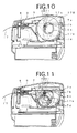
- Figs. 10 and 11 show a remaining quantity detecting operation of a rolled paper 17B having the largest diameter core 17b.
- the lug 7b and the lever 7 is rotated in the counterclockwise direction in Fig. 4a is engaged with a fourth notch (4) so that the paper detecting second device 7d is positioned at a right end position as shown in Fig. 10.
- the second device 7d is connected to a control circuit 14 by operating the changeover switch.
- the light emitted from the light emitting element is reflected from the side of the paper 17B and received by the light receiving element.
- the light receiving element produces the output signal which is applied to the control circuit 14.
- the control circuit 14 does not generate the end signal.
- the control circuit When the remaining quantity of the rolled paper 17B approaches the end of the paper, and the surface of the rolled paper leaves from the first device 7d (Fig. 11). The light receiving element does not produce the output signal. Thus, the control circuit generates the end signal so that the warning lamp L is lighted and buzzer is operated .
- the second (2) or third (3) notch is selected.
- the ends of rolled papers which are different in core diameter can be detected.
Landscapes
- Controlling Rewinding, Feeding, Winding, Or Abnormalities Of Webs (AREA)
- Accessory Devices And Overall Control Thereof (AREA)
- Handling Of Continuous Sheets Of Paper (AREA)
Abstract
Description
- The present invention relates to a device for detecting remaining quantity of rolled papers in a device such as a printer.
- In such a device using the rolled paper as the printer, it is necessary to be informed that the remaining quantity of the rolled paper is little, even if a rolled paper different from a previously used rolled paper in diameter of the core is used.
- In a conventional detecting device, a detecting plate for operating a detector switch must be moved in accordance with the change of the diameter of the core of the rolled paper. In order to move the detecting plate, a fixing screw is released, the detecting plate is moved along a guide, and the screw must be turned to fasten the plate. Therefore, the adjusting operation is troublesome.
- An object of the present invention is to provide a detecting device which may be easily adjusted in accordance with the change of the diameter of the core.
- According to the present invention, there is provided a device for detecting remaining quantity of rolled papers comprising, a housing having a bottom for supporting a rolled paper, detector means for detecting a peripheral position of the rolled paper supported on the bottom when the peripheral position approaches an inner end of the paper and for generating an output signal, positioning means for positioning the detector means at a position dependent on a radius of a core of the rolled paper, a control circuit responsive to the output signal for informing that the rolled paper reaches the inner end.
- The detector means is at least one photodetector mounted on a rotatable lever, and the positioning means is notches provided in the housing and a movable knob having a lug engaged with one of the notches.
- The photodetector comprises a light emitting element for emitting light to a side of the rolled paper, and a light receiving element for receiving the light reflected from the side.
- These and other objects and features of the present invention will become more apparent from the following detailed description with reference to the accompanying drawings.
-
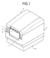
- Fig. 1 is a perspective view showing a printer in which a detecting device of the present invention is provided;
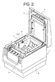
- Fig. 2 is a perspective view of the printer when a cover is opened;
- Fig. 3 is a sectional side view of the printer;
- Figs. 4 and 5 are enlarged views in a circle B of Fig. 3;
- Fig. 5a is an enlarged view of a part of Fig. 5;
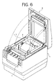
- Fig. 6 is a perspective view showing a state wherein a rolled paper is mounted;
- Fig. 7 is a perspective view showing an operating state of the printer; and
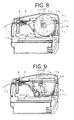
- Figs. 8 to 11 are sectional side views for explaining detecting operations
-
- Referring to Fig. 1 showing a perspective view of a printer in which a device of the present invention is mounted, the printer comprises a
housing 1,cover 2 and abottom case 15 in which an AC adapter 16 (Fig. 3) is mounted. There is provided apaper feeding switch 3, a warning lamp L, a coverlock release button 4, and a paper discharge opening 5 on the front panel of the printer. - Referring to Figs. 2 and 3, in the
housing 1, a rolledpaper housing space 6 is provided and aplaten 9 is vertically slidably mounted. A platen push lever 12 is rotatably mounted by a shaft 12a and urged to theplaten 9 by aspring 13 so as to press the platen to aprint head 8 mounted in thecover 2. In a side wall 6d of the rolledpaper housing space 6, an opening 6b having a sector shape is formed. In the opening 6b, a part of a remainingquality detector lever 7 is exposed. - Referring to Figs. 4, 5 and 5a, the
lever 7 is pivotaly mounted on the side wall 6d by a shaft 7e. On the top of thelever 7, a knob 7a and an engaging lug 7b are formed. A recess 6a is formed in the side wall and four notches 6c are formed on the bottom of the recess 6a. The bottom 6a is arced, having the radius from the shaft 7e. - On the exposed part of the
lever 7, a paper detecting first device 7c and a paper detecting second device 7d are provided. Each of the first and second devices 7c and 7d comprises a light emitting element 7f and light receiving element 7g. - The
lever 7 is made of a thin plastic plate so that the upper portion of thelever 7 than the shaft 7e can be bent by pushing the knob 7a so as to be removed from the side wall 6d. - By bending the
lever 7, the lug 7b is removed from the notch 6c so that the lever can be pivoted about the shaft 7e. Thus, the lug 7b can be engaged with a desired notch. - Referring to Fig. 6, a rolled
paper 17 is mounted in thespace 6. The rolledpaper 17 is rotatably supported on the bottom of thespace 6 and held by a lateral rod 6d as shown in Fig. 8. The end of the paper in Fig. 6 is pulled out of thehousing 1 and thecover 2 is closed. As shown in Fig. 8, the paper is nipped between theplaten 9 and theprint head 8. - Figs. 8 and 9 show a remaining quantity detecting operation of a rolled paper 17A having the smallest diameter core 17a. In the case of the smallest diameter core 17a, the lug 7b is engaged with a first notch (1) so that the paper detecting first device 7c is positioned at a left end position as shown in Fig. 8. The first device 7c is connected to a control circuit 14 by manually operating a changeover switch provided in the control circuit 14.
- While sufficient amount paper exists, the light emitted from the light emitting element 7f is reflected from the side of the paper 17A and received by the light receiving element 7g. The light receiving element 7g produces an output signal which is applied to the control circuit 14. In such a condition, the control circuit 14 does not generate an end signal.
- When the remaining quantity of the rolled paper 17A approaches the end of paper, the surface of the rolled paper leaves from the first device 7c as shown in Fig. 9. As a result, the light emitted from the light emitting element does not reflect from the side of the rolled paper. Thus, the light receiving element 7g does not produce the output signal. In response to the disappearance of the output signal, the control circuit 14 generates the end signal so that the warning lamp L is lighted and a buzzer (not shown) emits a warning sound.
- Figs. 10 and 11 show a remaining quantity detecting operation of a rolled paper 17B having the largest diameter core 17b. In the case of the largest diameter core 17a, the lug 7b and the
lever 7 is rotated in the counterclockwise direction in Fig. 4a is engaged with a fourth notch (4) so that the paper detecting second device 7d is positioned at a right end position as shown in Fig. 10. The second device 7d is connected to a control circuit 14 by operating the changeover switch. - In the condition of Fig. 10, the light emitted from the light emitting element is reflected from the side of the paper 17B and received by the light receiving element. The light receiving element produces the output signal which is applied to the control circuit 14. The control circuit 14 does not generate the end signal.
- When the remaining quantity of the rolled paper 17B approaches the end of the paper, and the surface of the rolled paper leaves from the first device 7d (Fig. 11). The light receiving element does not produce the output signal. Thus, the control circuit generates the end signal so that the warning lamp L is lighted and buzzer is operated .
- When a rolled paper having an intermediate diameter core, the second (2) or third (3) notch is selected.
- In accordance with the present invention, the ends of rolled papers which are different in core diameter can be detected.
- While the invention has been described in conjunction with preferred specific embodiment thereof, it will be understood that this description is intended to illustrate and not limit the scope of the invention, which is defined by the following claims.
Claims (3)
- A device for detecting remaining quantity of rolled papers comprising:a housing having a bottom for supporting a rolled paper;detector means for detecting a peripheral position of the rolled paper supported on the bottom when the peripheral position approaches an inner end of the paper and for generating an output signal;positioning means for positioning the detector means at a position dependent on a radius of a core of the rolled paper;a control circuit responsive to the output signal for informing that the rolled paper reaches the inner end.
- The device for detecting remaining quantity of rolled papers according to claim 1 wherein the detector means is at least one photodetector mounted on a rotatable lever, and the positioning means is notches provided in the housing and a movable knob having a lug engaged with one of the notches.
- The device for detecting remaining quantity of rolled papers according to claim 2 wherein the photodetector comprises a light emitting element for emitting light to a side of the rolled paper, and a light receiving element for receiving the light reflected from the side.
Applications Claiming Priority (2)
| Application Number | Priority Date | Filing Date | Title |
|---|---|---|---|
| JP18096099A JP4261686B2 (en) | 1999-06-25 | 1999-06-25 | Roll paper remaining amount detecting means and printer provided with this roll paper remaining amount detecting means |
| JP18096099 | 1999-06-25 |
Publications (3)
| Publication Number | Publication Date |
|---|---|
| EP1063189A2 true EP1063189A2 (en) | 2000-12-27 |
| EP1063189A3 EP1063189A3 (en) | 2004-04-07 |
| EP1063189B1 EP1063189B1 (en) | 2007-01-24 |
Family
ID=16092299
Family Applications (1)
| Application Number | Title | Priority Date | Filing Date |
|---|---|---|---|
| EP00830435A Expired - Lifetime EP1063189B1 (en) | 1999-06-25 | 2000-06-22 | Device for detecting remaining quantity of rolled papers |
Country Status (4)
| Country | Link |
|---|---|
| US (1) | US6502784B1 (en) |
| EP (1) | EP1063189B1 (en) |
| JP (1) | JP4261686B2 (en) |
| DE (1) | DE60033087T2 (en) |
Cited By (2)
| Publication number | Priority date | Publication date | Assignee | Title |
|---|---|---|---|---|
| EP1172319A3 (en) * | 2000-07-11 | 2003-05-21 | Samsung Electronics Co., Ltd. | Apparatus of a printer for detecting termination of printing medium |
| CN104418142A (en) * | 2013-09-11 | 2015-03-18 | 芯发威达电子(上海)有限公司 | Paper roll device with upper cover opening and closing detection function |
Families Citing this family (24)
| Publication number | Priority date | Publication date | Assignee | Title |
|---|---|---|---|---|
| JP2004246226A (en) * | 2003-02-17 | 2004-09-02 | Fuji Photo Optical Co Ltd | Magazine and image recording apparatus using the same |
| EP1752304B1 (en) | 2005-08-09 | 2008-03-26 | Seiko Epson Corporation | Roll paper printer |
| FR2892053B1 (en) * | 2005-10-14 | 2007-12-07 | Sagem Defense Securite | PRINTING DEVICE WITH ASSERTED DRIVE SPEED |
| JP4715442B2 (en) * | 2005-10-18 | 2011-07-06 | セイコーエプソン株式会社 | Roll paper printer |
| US7878724B2 (en) * | 2005-12-27 | 2011-02-01 | Seiko Epson Corporation | Printer |
| US7748918B2 (en) * | 2006-11-17 | 2010-07-06 | International Business Machines Corporation | Printer paper waste reduction method and computer program product |
| JP4459219B2 (en) * | 2006-12-08 | 2010-04-28 | 東芝テック株式会社 | Paper feeding device and printer having the same |
| ES2629803T3 (en) * | 2007-10-22 | 2017-08-14 | San Jamar, Inc. | Band material dispenser with differentiation function |
| US20090308967A1 (en) * | 2008-06-17 | 2009-12-17 | International Business Machines Corporation | Multiple attitude low paper sensor mechanism |
| JP2010036374A (en) * | 2008-08-01 | 2010-02-18 | Seiko Epson Corp | Printing apparatus, printing system, near-end notification method, and control program |
| US20100028067A1 (en) * | 2008-08-01 | 2010-02-04 | Seiko Epson Corporation | Printing Device, Printing System, and Near-End Notification Method |
| JP5017309B2 (en) * | 2009-03-30 | 2012-09-05 | シチズンホールディングス株式会社 | Printer |
| JP5543222B2 (en) * | 2010-01-05 | 2014-07-09 | シチズンホールディングス株式会社 | Printer device |
| MX2012012200A (en) | 2010-04-22 | 2012-12-17 | Colman Group Inc | Insert for use with a roll of web material, and providing a unique identifier for the roll of web material. |
| USD802326S1 (en) | 2011-09-14 | 2017-11-14 | San Jamar, Inc. | Insert for a web material dispenser |
| JP5576345B2 (en) * | 2011-09-30 | 2014-08-20 | 東芝テック株式会社 | Paper storage device and printer having the same |
| JP5851270B2 (en) * | 2012-02-15 | 2016-02-03 | シチズンホールディングス株式会社 | Printer |
| DE102013103918A1 (en) | 2013-04-18 | 2014-10-23 | Océ Printing Systems GmbH & Co. KG | A method of operating a printer and determining a residual length of a record carrier web wound on a roll |
| JP6257981B2 (en) * | 2013-09-24 | 2018-01-10 | 富士通コンポーネント株式会社 | Near-end detection device, printer |
| WO2017010997A1 (en) | 2015-07-14 | 2017-01-19 | Hewlett-Packard Development Company, L.P. | Wiping material usage indicators |
| USD860674S1 (en) | 2018-02-06 | 2019-09-24 | San Jamar, Inc. | Towel dispenser |
| US10434800B1 (en) * | 2018-05-17 | 2019-10-08 | Datamax-O'neil Corporation | Printer roll feed mechanism |
| JP7128772B2 (en) * | 2019-05-23 | 2022-08-31 | シチズン時計株式会社 | printer |
| USD904066S1 (en) | 2019-09-19 | 2020-12-08 | Georgia-Pacific LLC | Core plug |
Family Cites Families (4)
| Publication number | Priority date | Publication date | Assignee | Title |
|---|---|---|---|---|
| JPS624166A (en) * | 1985-06-26 | 1987-01-10 | Toshiba Corp | Remainder detecting system for roll-like wound material |
| JP2705890B2 (en) * | 1993-10-21 | 1998-01-28 | 富士通アイソテック株式会社 | Roll paper limit remaining detector |
| US5713678A (en) * | 1996-07-05 | 1998-02-03 | Axiohm Ipb Inc. | Low-paper sensing apparatus |
| JP3907288B2 (en) * | 1997-10-31 | 2007-04-18 | 富士通アイソテック株式会社 | Printer device using roll paper |
-
1999
- 1999-06-25 JP JP18096099A patent/JP4261686B2/en not_active Expired - Fee Related
-
2000
- 2000-06-22 EP EP00830435A patent/EP1063189B1/en not_active Expired - Lifetime
- 2000-06-22 DE DE60033087T patent/DE60033087T2/en not_active Expired - Lifetime
- 2000-06-23 US US09/599,830 patent/US6502784B1/en not_active Expired - Lifetime
Non-Patent Citations (1)
| Title |
|---|
| None |
Cited By (3)
| Publication number | Priority date | Publication date | Assignee | Title |
|---|---|---|---|---|
| EP1172319A3 (en) * | 2000-07-11 | 2003-05-21 | Samsung Electronics Co., Ltd. | Apparatus of a printer for detecting termination of printing medium |
| US6629666B2 (en) | 2000-07-11 | 2003-10-07 | Samsung Electronics Co., Ltd. | Apparatus of a printer for detecting termination of printing medium |
| CN104418142A (en) * | 2013-09-11 | 2015-03-18 | 芯发威达电子(上海)有限公司 | Paper roll device with upper cover opening and closing detection function |
Also Published As
| Publication number | Publication date |
|---|---|
| EP1063189B1 (en) | 2007-01-24 |
| DE60033087D1 (en) | 2007-03-15 |
| DE60033087T2 (en) | 2007-12-13 |
| JP4261686B2 (en) | 2009-04-30 |
| US6502784B1 (en) | 2003-01-07 |
| JP2001002296A (en) | 2001-01-09 |
| EP1063189A3 (en) | 2004-04-07 |
Similar Documents
| Publication | Publication Date | Title |
|---|---|---|
| US6502784B1 (en) | Device for detecting remaining quantity of rolled papers | |
| US7070348B2 (en) | Roll sheet holder and tape printer | |
| US7176451B2 (en) | Photoelectric switch device having a detection result indicator | |
| JPH10152230A (en) | Sheet set sensor actuator for document or copy sheet tray | |
| EP0860747B1 (en) | Apparatus for designating paper cassettes in printers and copiers | |
| JPH07117919A (en) | Roll paper limit detector | |
| EP0920397A4 (en) | Adjustable low paper sensor | |
| JPS63280572A (en) | Image processor | |
| AU753299B2 (en) | Media sensor system for printer mechanism | |
| JP2001130808A (en) | Printer | |
| US20020023983A1 (en) | Apparatus of a printer for detecting termination of printing medium | |
| US6565080B1 (en) | Imaging media loading guide | |
| EP1231070A2 (en) | Printer | |
| US11758062B1 (en) | Image forming apparatus | |
| JPH092672A (en) | Paper feeder | |
| US4918485A (en) | Roll film camera | |
| KR100233119B1 (en) | Apparatus for detecting paper of printer | |
| KR100354072B1 (en) | Low Paper Detecting Appratus for Printer | |
| JP2875657B2 (en) | Image forming device | |
| JPH1048905A (en) | Device open / close detection mechanism | |
| KR100715164B1 (en) | Photoelectric switch device | |
| JPS6330763Y2 (en) | ||
| KR20060019107A (en) | Printer's remaining paper detector | |
| JPS61204282U (en) | ||
| KR950001161Y1 (en) | Paper size display device of paper cassette |
Legal Events
| Date | Code | Title | Description |
|---|---|---|---|
| PUAI | Public reference made under article 153(3) epc to a published international application that has entered the european phase |
Free format text: ORIGINAL CODE: 0009012 |
|
| AK | Designated contracting states |
Kind code of ref document: A2 Designated state(s): AT BE CH CY DE DK ES FI FR GB GR IE IT LI LU MC NL PT SE |
|
| AX | Request for extension of the european patent |
Free format text: AL;LT;LV;MK;RO;SI |
|
| PUAL | Search report despatched |
Free format text: ORIGINAL CODE: 0009013 |
|
| AK | Designated contracting states |
Kind code of ref document: A3 Designated state(s): AT BE CH CY DE DK ES FI FR GB GR IE IT LI LU MC NL PT SE |
|
| AX | Request for extension of the european patent |
Extension state: AL LT LV MK RO SI |
|
| 17P | Request for examination filed |
Effective date: 20041005 |
|
| AKX | Designation fees paid |
Designated state(s): DE GB |
|
| GRAP | Despatch of communication of intention to grant a patent |
Free format text: ORIGINAL CODE: EPIDOSNIGR1 |
|
| RAP1 | Party data changed (applicant data changed or rights of an application transferred) |
Owner name: CITIZEN WATCH CO., LTD. |
|
| GRAS | Grant fee paid |
Free format text: ORIGINAL CODE: EPIDOSNIGR3 |
|
| GRAA | (expected) grant |
Free format text: ORIGINAL CODE: 0009210 |
|
| AK | Designated contracting states |
Kind code of ref document: B1 Designated state(s): DE GB |
|
| REG | Reference to a national code |
Ref country code: GB Ref legal event code: FG4D |
|
| REF | Corresponds to: |
Ref document number: 60033087 Country of ref document: DE Date of ref document: 20070315 Kind code of ref document: P |
|
| RAP2 | Party data changed (patent owner data changed or rights of a patent transferred) |
Owner name: CITIZEN HOLDINGS CO., LTD. |
|
| PLBE | No opposition filed within time limit |
Free format text: ORIGINAL CODE: 0009261 |
|
| STAA | Information on the status of an ep patent application or granted ep patent |
Free format text: STATUS: NO OPPOSITION FILED WITHIN TIME LIMIT |
|
| 26N | No opposition filed |
Effective date: 20071025 |
|
| REG | Reference to a national code |
Ref country code: DE Ref legal event code: R082 Ref document number: 60033087 Country of ref document: DE Representative=s name: BOETERS & LIECK, DE Ref country code: DE Ref legal event code: R081 Ref document number: 60033087 Country of ref document: DE Owner name: CITIZEN WATCH CO., LTD., NISHITOKYO-SHI, JP Free format text: FORMER OWNER: CITIZEN HOLDINGS CO.,LTD., TOKIO, JP |
|
| PGFP | Annual fee paid to national office [announced via postgrant information from national office to epo] |
Ref country code: DE Payment date: 20190612 Year of fee payment: 20 |
|
| PGFP | Annual fee paid to national office [announced via postgrant information from national office to epo] |
Ref country code: GB Payment date: 20190619 Year of fee payment: 20 |
|
| REG | Reference to a national code |
Ref country code: DE Ref legal event code: R071 Ref document number: 60033087 Country of ref document: DE |
|
| REG | Reference to a national code |
Ref country code: GB Ref legal event code: PE20 Expiry date: 20200621 |
|
| PG25 | Lapsed in a contracting state [announced via postgrant information from national office to epo] |
Ref country code: GB Free format text: LAPSE BECAUSE OF EXPIRATION OF PROTECTION Effective date: 20200621 |