EP1752304B1 - Roll paper printer - Google Patents
Roll paper printer Download PDFInfo
- Publication number
- EP1752304B1 EP1752304B1 EP06016238A EP06016238A EP1752304B1 EP 1752304 B1 EP1752304 B1 EP 1752304B1 EP 06016238 A EP06016238 A EP 06016238A EP 06016238 A EP06016238 A EP 06016238A EP 1752304 B1 EP1752304 B1 EP 1752304B1
- Authority
- EP
- European Patent Office
- Prior art keywords
- paper
- printer
- roll
- detection lever
- cover unit
- Prior art date
- Legal status (The legal status is an assumption and is not a legal conclusion. Google has not performed a legal analysis and makes no representation as to the accuracy of the status listed.)
- Expired - Fee Related
Links
Images


Classifications
-
- B—PERFORMING OPERATIONS; TRANSPORTING
- B41—PRINTING; LINING MACHINES; TYPEWRITERS; STAMPS
- B41J—TYPEWRITERS; SELECTIVE PRINTING MECHANISMS, i.e. MECHANISMS PRINTING OTHERWISE THAN FROM A FORME; CORRECTION OF TYPOGRAPHICAL ERRORS
- B41J15/00—Devices or arrangements of selective printing mechanisms, e.g. ink-jet printers or thermal printers, specially adapted for supporting or handling copy material in continuous form, e.g. webs
- B41J15/04—Supporting, feeding, or guiding devices; Mountings for web rolls or spindles
-
- B—PERFORMING OPERATIONS; TRANSPORTING
- B41—PRINTING; LINING MACHINES; TYPEWRITERS; STAMPS
- B41J—TYPEWRITERS; SELECTIVE PRINTING MECHANISMS, i.e. MECHANISMS PRINTING OTHERWISE THAN FROM A FORME; CORRECTION OF TYPOGRAPHICAL ERRORS
- B41J11/00—Devices or arrangements of selective printing mechanisms, e.g. ink-jet printers or thermal printers, for supporting or handling copy material in sheet or web form
- B41J11/0075—Low-paper indication, i.e. indicating the state when copy material has been used up nearly or completely
-
- B—PERFORMING OPERATIONS; TRANSPORTING
- B41—PRINTING; LINING MACHINES; TYPEWRITERS; STAMPS
- B41J—TYPEWRITERS; SELECTIVE PRINTING MECHANISMS, i.e. MECHANISMS PRINTING OTHERWISE THAN FROM A FORME; CORRECTION OF TYPOGRAPHICAL ERRORS
- B41J29/00—Details of, or accessories for, typewriters or selective printing mechanisms not otherwise provided for
- B41J29/02—Framework
-
- B—PERFORMING OPERATIONS; TRANSPORTING
- B41—PRINTING; LINING MACHINES; TYPEWRITERS; STAMPS
- B41J—TYPEWRITERS; SELECTIVE PRINTING MECHANISMS, i.e. MECHANISMS PRINTING OTHERWISE THAN FROM A FORME; CORRECTION OF TYPOGRAPHICAL ERRORS
- B41J29/00—Details of, or accessories for, typewriters or selective printing mechanisms not otherwise provided for
- B41J29/12—Guards, shields or dust excluders
- B41J29/13—Cases or covers
-
- B—PERFORMING OPERATIONS; TRANSPORTING
- B41—PRINTING; LINING MACHINES; TYPEWRITERS; STAMPS
- B41J—TYPEWRITERS; SELECTIVE PRINTING MECHANISMS, i.e. MECHANISMS PRINTING OTHERWISE THAN FROM A FORME; CORRECTION OF TYPOGRAPHICAL ERRORS
- B41J29/00—Details of, or accessories for, typewriters or selective printing mechanisms not otherwise provided for
- B41J29/46—Applications of alarms, e.g. responsive to approach of end of line
- B41J29/48—Applications of alarms, e.g. responsive to approach of end of line responsive to breakage or exhaustion of paper or approach of bottom of paper
Definitions
- the present invention relates to a roll paper printer having a paper amount detection device featuring easy replacement of the roll paper.
- One type of known roll paper printers has the paper roll loaded so that it can simply roll on the bottom of the paper compartment.
- the roll paper typically comprises a long tape of recording paper wound into a roll on a hollow core that has a hole in the center.
- This type of roll paper printer also commonly has a paper amount detection device for detecting the near-end of the roll when there is little roll paper left on the core.
- US 5,884,861 A discloses a roll paper printer according to the pre-characterizing portion of claim 1. This known printer has a detection lever that is inserted into the hole in the core of the roll paper once the diameter of the paper roll has decreased to a certain value.
- This lever is pressed by an urging member against an end face of the paper roll held in the paper compartment at a predetermined height above the bottom of the paper compartment.
- the detection lever slips off the end face of the roll paper and enters the hole in the paper roll core.
- the detection lever is not limited to a mechanism that inserts the lever into the paper roll core, and can be a mechanism causing the lever to separate in the direction of the outer circumferential edge of the roll's end face. That the amount of remaining roll paper is low can be known by using a mechanical or other type of detection switch to detect movement of such a detection lever that separates from the end face of the paper roll into the core hole or to the outer surface of the roll.
- a recessed channel into which the paper roll is dropped once the diameter has become small, and inclined guide surfaces for guiding the paper roll into this channel are formed in the bottom of the paper compartment.
- JP-A 9-254474 and JP-A 2003-11453 (corr. to US 5,884,861 A ) teach a roll paper printer having a paper compartment and a paper amount detection device that use this type of detection lever to detect the near-end of the roll paper.
- the detection lever of the detection device protrudes into the paper compartment.
- the user When loading the paper roll, such as when replacing the roll paper, the user must therefore push and retract the detection lever from the paper compartment using the end of the paper roll in order to place the paper roll into the paper compartment. If the detection lever is inserted into the core hole when removing the paper roll, the detection lever must also be pushed to the side and retracted so that the paper roll can be removed.
- the detection lever may not be able to retract as quickly, resulting in the detection lever being caught by the core hole of the roll paper and interfering with loading and removing the roll paper. The detection lever may even be damaged.
- a taper with a large angle in the roll paper loading and removal direction must be rendered on the detection lever so that the detection lever can be pushed and retracted smoothly.
- rendering a taper with a large angle on the detection lever causes the problem of a drop in detection precision because setting the point at which the detection lever is inserted into the paper roll core with precision as the roll paper decreases to a predetermined remaining amount is more difficult than with a detection lever that does not have a taper.
- the same problem also occurs with a mechanism whereby the detection lever separates to the outer circumference of the roll paper.
- An object of the present invention is to provide a roll paper printer having a precise paper amount detection device that does not interfere with loading and removing the paper roll.
- Opening the cover unit of a roll paper printer causes the detection lever to move in the retraction direction in which the detection lever retracts from the paper compartment.
- the paper roll will not contact the detection lever when the paper roll is loaded into the paper compartment.
- the detection lever will be completely retracted from the core to a position where the detection lever will not interfere with the paper roll, and the paper roll or core can therefore be easily removed. The detection lever is therefore prevented from contacting the paper roll and interfering with the ease of loading or removing roll paper from the paper compartment.
- a roll paper printer according to a first embodiment of the invention is described below with reference to FIG. 1 to FIG. 8 .
- FIG. 1 is a perspective external view of a roll paper printer according to the present invention
- FIG. 2 an is perspective view showing the printer when the cover unit is open.
- the roll paper printer 1 has a printer chassis 2 with an operable cover unit 3 attached at the front.
- An operating panel unit 4 is disposed at a front corner of the printer chassis 2.
- a paper exit 5 extending widthwise to the printer is formed at the top part of the cover unit 3 at the front of the printer.
- the printer chassis 2 is covered by a box-like printer case 6 that is long in the front-to-back (longitudinal) direction of the printer and is open at the front and bottom sides.
- a operable cover case 7 that defines the printer front is attached at the front of the cover unit 3.
- Operating an operating lever 8 located at the operating panel unit 4 releases a cover lock not shown, thereby releasing and causing the cover unit 3 to swing forward and open by pivoting on the bottom end part of the cover unit 3. Opening the cover unit 3 opens a roll paper loading opening 9a at the front of the internal paper compartment 9 so that a paper roll 10 can be replaced.
- a state indicator group 4a of LEDs for example, a feed button 4b, and a power switch 4c are provided on the front of the operating panel unit 4.
- a paper amount detection mechanism for detecting when the paper roll stored inside has decreased to a predetermined size (a predetermined diameter) is also disposed inside the paper compartment 9.
- a control unit not shown disposed inside the printer 1 detects that the paper roll has decreased to or below this predetermined amount, an indicator in the state indicator group 4a is driven to light steadily or blink, for example, to alert the user. If the printer 1 is connected to a terminal device not shown, a message may also be presented on the terminal device, for example.
- FIG. 3 is a schematic view of the inside of the printer 1.
- the paper compartment 9 formed inside the printer 1 is surrounded by a curved bottom panel 12 extending widthwise to the printer, a top panel 13 extending widthwise to the printer, and front panel 14 extending widthwise to the printer and generally conforming to the shape of the paper roll 10.
- the paper roll 10 is held so that it can rotate freely on the bottom panel 12 inside the paper compartment 9 as a paper guide.
- a core hole 101 is rendered in the center of the paper roll 10.
- the tape of recording paper 10a that is delivered from the paper roll 10 is pulled to the front past the printing position between the platen roller 15 and the thermal print head 16, and is discharged to the front of the printer from the paper exit 5 disposed in front of the printing position.
- a scissor type cutting device 20 is disposed in front of the paper exit 5.
- the cutting device 20 has a fixed blade 21 disposed on the printer chassis side, and a movable blade 22 and a drive mechanism 23 for the movable blade disposed on the cover unit side.
- the fixed blade 21 is disposed substantially horizontally widthwise to the printer with the cutting edge 21a facing forward.
- the movable blade 22 is disposed substantially vertically widthwise to the printer with the cutting edge 22a facing up at a position substantially directly below the cutting edge 21 a of the fixed blade 21.
- FIG. 4 is a side view showing the mechanical part of the printer 1 with the printer case 6 and the cover case 7 removed.
- FIG. 5A and FIG. 5B are a perspective view and a side view, respectively, with one side panel removed as denoted by the imaginary line to show the internal structure.
- FIG. 6A and FIG. 6B are a perspective view and a side view, respectively, similar to FIG. 5 but with the cover unit open.
- the printer chassis 2 has a base panel 31 defining the printer bottom, right and left side panels 32 and 33 rising vertically from the base panel 31 with a specific gap therebetween, and a back panel 30 disposed between the back of these right and left side panels 32 and 33 widthwise to the printer.
- a head mounting panel 34 is disposed horizontally widthwise to the printer across the gap between the top portions of the side panels 32 and 33.
- the thermal print head 16 is mounted at the bottom of the head mounting panel 34 with the head surface 16a facing down and substantially horizontal (see FIG. 3 ).
- the top panel 13 of the paper compartment 9 is located below the back part of the head mounting panel 34.
- the bottom panel 12 of the paper compartment 9 is located on top of the base panel 31.
- a fixed blade mounting plate 35 is disposed horizontally widthwise to the printer above the head mounting panel 34.
- the fixed blade 21 of the cutting device 20 is attached substantially horizontally and facing forward at the front bottom part of the fixed blade mounting plate 35.
- the fixed blade mounting plate 35 is disposed between the top edges of the right and left pivot plates 37 (only one pivot plate 37 is shown in the figures), which are located outside of the side panels 32 and 33.
- the pivot plates 37 can pivot (move) slightly in the longitudinal (front-to-back) direction of the printer on the bottom end portions 37a (only one bottom portion 37a is shown in the figures) of the pivot plates 37.
- the movable blade 22 pivots up from below while pushing the fixed blade 21 to the back so that the cutting edges 21a and 22a contact at a point and cut the recording paper 10a.
- the pivot plates 37 support the fixed blade 21 so that the fixed blade 21 retracts slightly while cutting the paper.
- a paper amount detection mechanism 50 for detecting when the supply of roll paper held in the paper compartment 9 has decreased to or below a predetermined amount is assembled to the bottom end portion on the outside of the side panel 33.
- the cover unit 3 can open to a predetermined angle to the front of the printer pivoting on support pins 41, 42 affixed at the bottom end part of the side panels 32 and 33 of the printer chassis 2.
- the cover unit 3 has a front panel portion 43 and narrow side panel portions 44 and 45 rendered by bending the right and left edges of the front panel portion 43 perpendicularly toward the back of the printer.
- the movable blade 22 and the drive mechanism 23 of the cutting device 20 are disposed at the front of the front panel portion 43, and are covered by a protective panel 24.
- the front of the protective panel 24 is covered by the cover case 7 (see FIG. 3 ).
- the platen roller 15 is disposed freely rotatably between the side panel portions 44 and 45.
- the front panel 14 of the paper compartment 9 affixed to the back side of the front panel portion 43 is located below the platen roller 15.
- the front panel 14 of the paper compartment 9, the platen roller 15, and the movable blade 22 of the cutting device 20 are mounted in the cover unit 3. Opening the cover unit 3 opens the paper compartment 9 as shown in FIG. 2 and FIG. 5 , and opens the paper transportation path from the paper compartment 9 past the printing position and paper cutting position to the paper exit 5. Therefore, when a specific length of recording paper 10a is pulled from the paper roll 10 inside the paper compartment 9 and the cover unit 3 is then closed, the recording paper 10a is automatically set and threaded through the paper transportation path.
- FIG. 7A, FIG. 7B, and FIG. 7C are a partial perspective view, a plan view, and a side view of the paper amount detection mechanism 50.
- FIG. 8A, FIG. 8B, and FIG. 8C are a partial perspective view, a plan view, and a side view of the detection mechanism 50 when the cover unit 3 is open.
- the detection mechanism 50 is described with reference to FIG. 4 to FIG. 8 .
- the detection mechanism 50 has a detection lever 51 attached to the outside of the side panel 33 of the printer chassis 2.
- the end of the detection lever 51 toward the back of the printer can pivot widthwise to the printer on a support stud 52 attached to the side panel 33.
- a torsion spring 52a (urging member) is disposed on the support stud 52, and this torsion spring 52a constantly urges the detection lever 51 to the inside widthwise to the printer (the projection direction).
- a detection tab 53 projecting to the inside widthwise to the printer is attached to the distal end part of the detection lever 51.
- the detection tab 53 projects to the inside of the paper compartment 9 through an opening not shown in the side panel 33.
- the bottom panel 12 of the paper compartment 9 is inclined slightly to the front, and as the paper roll 10 resting thereon is used (consumed), the diameter gradually decreases and the core hole 101 therefore gradually descends to the front.
- the core hole 101 of the paper roll 10A reaches a position 101A, i.e., the position where the detection tab 53 protrudes.
- the detection tab 53 is held pressed against the end face 10b of the paper roll 10 held in the paper compartment 9.
- the detection tab 53 enters the core hole 101.
- the base end of the detection lever 51 is linked to one switching part 54a of the detection switch 54.
- the detection switch 54 is off when the detection tab 53 contacts the end face 10b of the paper roll 10.
- the detection lever 51 pivots and the detection switch 54 linked to the back end of the detection lever 51 turns off.
- a control unit not shown detects the output (change) from the detection switch 54, and knows that the diameter of the paper roll 10 has dropped to a predetermined size, there is little recording paper 10a left, and the paper roll 10 will soon need replacing.
- the detection mechanism 50 has a retraction mechanism 55 for retracting the detection tab 53 of the detection lever 51 protruding into the paper compartment 9 from the paper compartment 9 in conjunction with the opening of the cover unit 3.
- the retraction mechanism 55 has a link bar 72 that moves reciprocally between a retreated position (first position) A separated from the detection tab 53 and an advanced position (second position) B pushing the detection tab 53 in the retraction direction.
- a tension spring 67 (urging member) pulls the link bar 72 to the retreated position A.
- the distal end part 72a of the link bar 72 is linked to rotate freely on a support pin 69 affixed to the side panel 45 of the cover unit 3.
- a long straight slot 72b is formed in the front-to-back direction of the printer in the back portion of the link bar 72.
- a slide pin 65 affixed to the side wall part 63 of the bottom panel 12 of the paper compartment 9 is slidably inserted into the slot 72b.
- the tension spring 67 is stretched between the slide pin 65 and a position on the bottom end of the back panel 30 of the printer chassis 2.
- Opening and closing the cover unit 3 causes the link bar 72 to move bidirectionally longitudinally to the printer between the retreated position A ( FIG. 7 ) and the advanced position B ( FIG. 8 ).
- a wide portion is formed in the middle part of the link bar 72, and a contact plate part 72c extending toward the bottom moves along a path past the position where the detection tab 53 protrudes.
- the contact plate part 72c is offset to the back side of the detection tab 53 as shown in FIG. 7B and FIG. 7C .
- the detection tab 53 is pushed to the outside by the contact plate part 72c, contacts the outside of the contact plate part 72c, and the detection tab 53 is thus held in the retracted position by the contact plate part 72c.
- the detection tab 53 of the detection lever 51 is thus retracted from the paper compartment 9 in conjunction with an opening of the cover unit 3.
- the detection tab 53 is thus removed from inside the paper compartment 9 when the paper roll 10 is replaced, and the detection tab 53 is therefore prevented from contacting the paper roll 10 and interfering with its replacement.
- the detection tab 53 is thus retracted, there is no need to form a tapered or sloped surface on the distal end part of the detection tab 53 to facilitate pushing the detection tab 53 out of the way when replacing the roll paper. Furthermore, because a taper or inclined surface can be omitted, the detection precision of the detection tab 53 can also be improved.
- tapers 53a and 53b toward the front and back of the printer are formed on the outside surface of the distal end of the overall cylindrically shaped detection tab 53.
- the front taper 53a is provided to prevent interference with the edge of the opening, not shown, in the side panel 33
- the back taper 53b is provided to facilitate being pushed by the contact plate part 72c of the link bar 72.
- a taper is not formed on the outside surfaces 53c and 53d perpendicular to tapers 53a and 53b, that is, on the sides in the direction of movement of the core hole 101 of the paper roll 10 (arrow C in FIG. 5B and FIG. 7 ). Because tapers are not formed on either side in the paper detection direction, the detection precision can be improved compared with arrangements having tapers on these surfaces.
- the bottom panel 12 changes between a substantially horizontal posture to a forward sloping posture in conjunction with an opening and closing of the cover unit 3.
- the cover unit 3 opens, the bottom panel 12 slopes forward and the paper roll 10 resting on the bottom panel 12 rolls forward due to its own weight.
- a mechanism for ejecting the paper roll 10 includes parts (including the link bar 72 and the tension spring 67) of the retraction mechanism 55 as further described below.
- the bottom panel 12 rests on the base panel 31 so that the front end side can move circularly freely in the front-to-back direction of the printer on support pin 61.
- Slide pins 65 (only one slide pin 65 is shown in the figures) are affixed protruding to the sides at the back of side wall parts 62, 63 on both sides of the bottom panel 12.
- Tension springs 67 (only one tension spring 67 is shown in the figures) are stretched and attached between these slide pins 65 and a place at the bottom end of the back panel 30. These left and right tension springs 67 hold the bottom panel 12 in a substantially horizontal position 12A in contact with the base panel 31.
- Identically shaped flat link bars 71 and 72 are disposed between these slide pins 65 and a vertically central part of the left and right side panel portions 44 and 45 of the cover unit 3.
- the distal end parts 71a and 72a of the link bars 71 and 72 are connected to support pins 68 and 69 so that the link bars 71 and 72 can pivot freely to the printer.
- Long straight slots 71 b and 72b are formed in the front-to-back direction of the printer in the back end part of the link bars 71 and 72, and the slide pins 65 are inserted to slide freely in these slots.
- These slide pins 65 are also inserted into arc-shaped guide holes 74 (only one guide hole 74 is shown in the figures) formed in the left and right side panels 32 and 33 as shown in FIG. 4 .
- These guide holes 74 are arcs of which the center is support pin 61. When the bottom panel 12 pivots on support pin 61, the slide pins 65 move along these guide holes 74.
- the left and right slide pins 65 of the bottom panel 12 are positioned at the front end of the slots 71 b and 72b in the left and right link bars 71 and 72. As shown in FIG. 4 , the slide pins 65 are positioned at the bottom end of the arc-shaped guide holes 74.
- the left and right link bars 71 and 72 When the cover unit 3 opens, the left and right link bars 71 and 72, of which the front ends are linked to the left and right side panel portions 44 and 45 of the cover unit 3, move forward.
- the left and right slide pins 65 attached to the bottom panel 12 of the paper compartment 9 are positioned at the front end of the slots 71 b and 72b in the link bars 71 and 72.
- the bottom panel 12 does not move until the link bars 71 and 72 have moved forward a predetermined distance and the back ends of these slots 71 b and 72b contact the slide pins 65.
- the left and right link bars 71 and 72 pull the slide pins 65 forward as the cover unit 3 continues to open.
- the bottom panel 12 to which these slide pins 65 are attached can move circularly on the support pin 61 at the front, and thus swings forward on the support pin 61 in conjunction with opening the cover unit 3.
- the bottom panel 12 is inclined a predetermined angle in the forward inclined position 12B.
- the bottom panel 12 changes from the substantially horizontal position 12A to the forward inclined position 12B in conjunction with an opening of the cover unit 3.
- the weight of the paper roll 10 causes the paper roll 10 to roll forward on the bottom panel 12 in this forward inclined position 12B.
- the paper roll 10 having little remaining recording paper 10a is ejected to the front as denoted by the imaginary lines in FIG. 6 .
- the paper roll 10 can therefore be easily removed from the top front of the open cover unit 3.
- the cover unit 3 After the bottom panel 12 started to pivot, the cover unit 3 is pulled to the back by the left and right tension springs 67 by means of the intervening link bars 71 and 72.
- the tension of the tension springs 67 thus prevents the cover unit 3 from opening suddenly to the front when the cover unit 3 is opened, and thus prevents damage resulting from the cover unit 3 hitting the surface on which the printer is placed with great force.
- a roll paper printer according to a second embodiment of the invention is described next with reference to FIG. 9 to FIG. 16 .
- FIG. 9 is an external perspective view of the roll paper printer
- FIG. 10 is a perspective view of the printer mechanism part as seen from the front left
- FIG. 11 is a perspective view of the printer mechanism part as seen from the front right
- FIG. 12 is a perspective view of the printer mechanism part when the cover unit is open
- FIG. 13 is a schematic diagram showing the internal arrangement of the roll paper printer.
- a printer 100 has a printer mechanism unit 200, a printer case 102 covering substantially all of the printer mechanism unit 200, and an operable cover case 103 covering the front of the printer mechanism unit 200 that is not covered by the printer case 102.
- a paper exit 108 extending widthwise to the cover case 103 is formed at the top part of the cover case 103.
- the printer case 102 covers part of the front, the top, the right and left sides, and the back of the printer mechanism unit 200. Disposed at the front of the printer case 102 are a power switch 104 for turning power to the printer 100 on and off, a state indicator group 105 for reporting the operating state of the printer 100, and a feed button 107 that is used to feed the paper roll 106 held inside the printer 100.
- the printer mechanism unit 200 comprises a printer chassis 101a and an operable cover unit 101b.
- the cover unit 101 b comprises the operable cover 109 and the cover case 103 attached to the front of the cover 109.
- the cover unit 101 b is connected by a hinge at the front bottom part of the printer mechanism unit 200, and can swing forward and open on this hinge.
- Operating the operating lever 120 disposed at the front of the printer case 102 releases a cover lock not shown and enables the cover 109 to swing on the bottom end part of the cover 109 from the closed position shown in FIG. 10 and FIG. 11 to the open position shown in FIG. 12 .
- the cover 109 opens, the roll paper loading opening 121a at the front of the paper compartment 121 formed inside the printer chassis 101a is opened as shown in FIG. 12 so that the paper roll 106 can be replaced.
- the paper roll 106 is generally a tape of recording paper (thermal paper in this embodiment of the invention) wound into a roll on a core.
- the printer chassis 101a has a base panel 125, right and left side panels 126 and 127 rising vertically from the right and left sides of the base panel 125, a back panel (not shown in the figure) disposed between the back of these right and left side panels 126 and 127 widthwise to the printer, and a top panel 128 disposed horizontally widthwise to the printer between the top portions of the side panels 126 and 127.
- a paper holder 129 forming the bottom and back of the paper compartment 121 extends between the left and right side panels 126 and 127.
- the cover unit 101b is affixed on a support shaft 130 between the front ends of the left and right side panels 126 and 127 so that the cover unit 101 b can pivot to an open position on the support shaft 130.
- the cover unit 101 b has a front panel portion 131 and side panel portions 132a and 132b bent at a right angle to the back of the printer from both sides of the front panel portion 131.
- a paper cutting device 134 having an internal movable blade 133 is disposed at the top outside of the front panel portion 131, and a fixed blade 135 is disposed above the cutting device 134 with the paper exit 108 therebetween.
- the fixed blade 135 is supported by a fixed blade support frame (not shown in the figure) disposed at the top part of the printer chassis 101a.
- the leading end of the recording paper from the paper roll 106 passes between the movable blade 133 and fixed blade 135 to the paper exit 108.
- the movable blade 133 pivots upward to the fixed blade 135 and cuts the recording paper in conjunction with the movable blade 133.
- a platen roller 136 is disposed freely rotatably between the top parts of the side panel portions 132a and 132b of the cover unit 101b as shown in FIG. 12 and FIG. 13 .
- a thermal print head 137 is disposed above the platen roller 136 at a position opposite the platen roller 136 as shown in FIG. 13 , and a plurality of resistance heating elements are disposed on the bottom of the thermal print head 137.
- the recording paper drawn off the paper roll 106 housed in the paper compartment 121 is held between the platen roller 136 and the thermal print head 137, and is conveyed to the paper exit 108 by rotating the platen roller 136 by means of a motor not shown.
- Text and images are printed on the recording paper by heat emitted from the resistance heating elements of the thermal print head 137 as the paper passes between the platen roller 136 and thermal print head 137.
- the thermal print head 137 is located on a head mounting panel 138 disposed below the printer case 102, and this head mounting panel 138 comprises a head support panel 139 for supporting the thermal print head 137, and a spring support panel 140 joined in unison with the head support panel 139 by a screw 138a.
- a first paper guide 151 for guiding the recording paper to the platen roller 136 is disposed below the head mounting panel 138.
- This first paper guide 151 comprises a curved portion 151a of which the distal end portion curves and extends upward.
- This curved portion 151a is proximally behind the platen roller 136.
- the recording paper curves upward at the curved portion 151a, and is then guided to the platen roller 136. This prevents creasing the edge of the paper in case force is applied to the paper from the side.
- a front panel 141 forming the back of the cover unit 101 b is affixed inside the cover unit 101 b.
- This front panel 141 comprises a base part 141a disposed at an angle toward the back of the printer, and a curved part 141 b continuing from the base part 141a and curving to the back.
- a second paper guide 152 disposed at the top end of the curved part 141 b contacts and causes the recording paper to curve when the paper roll 106 is consumed to a size at which the paper roll 106 does not contact the first paper guide 151 when the paper is conveyed.
- This second paper guide 152 is affixed so that it can pivot on a support pin 153, and is normally urged to the back by an urging member not shown. This second paper guide 152 also prevents creases in the edge of the paper.
- the paper compartment 121 is rendered between the paper holder 129 and the front panel 141 of the cover unit 101 b.
- the paper holder 129 comprises a bottom part 129a that inclines slightly to the front, and a back part 129b that extends curving upward from the back end of the bottom part 129a.
- the paper roll 106 held in the paper compartment 121 is delivered from the back side of the roll through the paper exit 108 located in front of the roll, and is discharged from the front of the printer 100. As a result, the outside of the paper roll 106 is pushed against the front panel 141 as the recording paper is discharged from the paper exit 108. Regardless of the size of the diameter of the roll, the paper roll 106 can always be supported by the bottom part 129a of the paper holder 129 and the cover unit 101 b.
- a first roller 142 extending widthwise to the printer is disposed at the base part 141a of the front panel 141 midway between the top and bottom of the base part 141 a, and substantially in the center in this embodiment.
- a second roller 143 also extending widthwise to the printer is disposed below the first roller 142 at the bottom end part of the base part 141a in this embodiment. More specifically, openings 144 and 145 are rendered widthwise to the printer in the base part 141 a of the front panel 141, and the shaft parts of these first and second rollers 142 and 143 are supported on the sides of these openings 144 and 145.
- These first and second rollers 142 and 143 have the same diameter, and the outer circumferential surfaces of the rollers protrude beyond the surface of the base part 141 a of the front panel 141.
- the first roller 142 contacts the paper roll 106 and reduces the rolling resistance of the paper roll 106 rolling inside the paper compartment 121.
- the second roller 143 contacts the outside of the paper roll 106 and likewise reduces the rolling resistance of the paper roll 106 rolling inside the paper compartment 121.
- That the diameter of the paper roll 106 is small means in this embodiment that the outside of the paper roll 106 does not contact the first roller 142. More specifically, the diameter of the paper roll 106 is less than approximately 50 mm.
- These first and second rollers 142 and 143 can assure that the paper roll 106 rolls smoothly regardless of the paper roll diameter as the size of the paper roll 106 gradually becomes smaller.
- These first and second rollers 142 and 143 are positioned so that at least one roller always contacts the outside of the paper roll 106 as the paper roll diameter decreases and the outside of the paper roll 106 does not directly contact the front panel 141 of the cover unit 101 b.
- a paper amount detection mechanism (near-end detection mechanism) 160 for detecting when the size of the paper roll 106 in the paper compartment 121 has decreased to a predetermined size is disposed as shown in FIG. 11 at the right side panel 127 of the printer chassis 101a.
- the detection mechanism 160 has a detection lever further described below that is pressed against an end face of the paper roll 106, which is pressed to the front panel 141 of the cover unit 101b of the paper compartment 121 during paper transportation.
- the near-end of the paper roll 106 is detected when the detection lever separates from the outer edge of the end face of the paper roll 106 to the side toward the back of the printer (away from the outer edge).
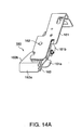
- the detection mechanism 160 comprises a frame 161 fixed to the right side panel 132, a detection lever 163 that is attached to the frame 161 freely pivotally on a support pin 162 and is pressed to the end face of the paper roll 106 in the paper compartment 121, a pressure spring 164 for urging the detection lever 163, and a detection switch 165 that operates according to the pivoting action of the detection lever 163.
- the detection lever 163 comprises a tapered surface 163a formed on the front end, a contact surface 163b formed on the side that is pressed against the end face of the roll paper, a rocker part 163c formed on the back end part for operating the detection switch 165, and a spring catch 163d for holding one end of the pressure spring 164.
- the contact surface 163b is tapered so that the width of the detection lever 163 increases to the front. In other words, the contact surface 163b tapers to the back of the printer.
- the frame 161 comprises a support part 161a that curves in a basic U-shape and supports the detection lever 163, and a spring catch 161b formed by bending one end of the support part 161a substantially perpendicularly for holding the other end of the pressure spring 164.
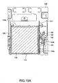
- this detection mechanism 160 is described next with reference to FIG. 15A and FIG. 15B .
- the contact surface 163b of the detection lever 163 is pressed against the end face 106a of the paper roll 106 as shown in FIG. 15A .
- the rocker part 163c of the detection lever 163 touches the detection switch 165 at this time, and the size of the roll paper is thus known to be greater than a predetermined size.
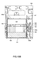
- the force of the pressure spring 164 causes the detection lever 163 to separate from the outer edge of the end face 106a of the paper roll 106 and move toward the back of the printer (to the outside of the outer edge), and project to the inside of the paper compartment 121 as shown in FIG. 15B .
- the rocker part 163c of the detection lever 163 separates from the detection switch 165.
- This causes the detection switch 165 to output a near-end state detection signal, that is, an electric signal indicating that the size of the paper roll 106 has decreased to a predetermined size or less.
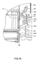
- This embodiment has a retraction mechanism for retracting the detection lever 163 to the outside of the paper compartment 121 in conjunction with the opening action of the cover unit 101 b when the cover unit 101 b is opened.
- the contact surface 163b functions as a surface engaging a moving plate 167 of the retraction mechanism.
- FIG. 16 shows the retraction mechanism, which is described next with reference to FIG. 12 and FIG. 16 .
- the right side panel 127 of the printer chassis 101a and the side panel 132b of the cover unit 101b are linked by this moving plate 167.
- the moving plate 167 slides forward (as indicated by arrow Y in the figure) along the right side panel 127.
- the distal end 167a of the moving plate 167 contacts and pushes the contact surface 163b of the detection lever 163 to the outside of the paper compartment 121.
- the detection lever 163 is retracted to the outside of the paper compartment 121.
- the detection lever 163 therefore does not protrude into the paper compartment 121 when the cover unit 101 b is open, and the paper roll 106 can be easily replaced or the paper roll 106 can be easily removed and inserted.
- the contact surface 163b functions as a guide surface for returning the detection lever 163 to the position pressing against the end face 106a. More specifically, when the paper roll 106 moves forward inside the paper compartment 121 from the back, the contact surface 163b of the detection lever 163 is pushed smoothly out by the outer edge portion of the paper roll 106. As a result, the contact surface 163b can again contact the end face 106a of the paper roll 106. This means that even if vibration, for example, causes the paper roll 106 to roll forward and back inside the paper compartment 121, the return of the paper roll 106 to the predetermined position enables continuing to detect when the paper roll 106 has decreased to the predetermined small size.
- the near-end of the paper roll 106 is detected when the detection lever 163 separates from the end face 106a of the paper roll 106. However, because the paper roll 106 may simply be moving inside the paper compartment 121, the near-end detection is preferably confirmed only after the near-end signal is output continuously for a predetermined time (such as 10 seconds).
- the detection lever 163 is retracted from the paper compartment 121 when the cover unit 101b opens, and closing the cover unit 101 b causes the detection lever 163 to protrude into the paper compartment 121.
- the detection lever 163 protrudes into the paper compartment 121 before the paper roll 106 is loaded into the paper compartment 121 when the cover unit 101b is closed, and the paper roll 106 is held between the detection lever 163 and cover unit 101b.
- the detection lever 163 protrudes into the paper compartment 121 before the paper roll 106 rolls into the paper compartment 121. As a result, the paper roll 106 may become stuck between the detection lever 163 and the front panel 141 of the cover unit 101b.
- a tapered surface 163a that rises to the top of the printer is formed at the front part of the detection lever 163 in this embodiment.
- the slope ⁇ of this tapered surface 163a is set so that if a small diameter roll 106 is between the tapered surface 163a and the front panel 141 of the cover unit 101 b, the paper roll 106 can easily ride over the tapered surface 163a.
- the paper roll 106 slides along the upward-facing tapered surface 163a and is stored in the paper compartment 121 when the cover unit 101b closes even if the detection lever 163 protrudes into the paper compartment 121 so that the paper roll 106 is between the detection lever 163 and the front panel 141 of the cover unit 101b before the paper roll 106 is stored in the paper compartment 121.
- a printer 100 has a retraction mechanism that moves the detection lever 163 in conjunction with an opening and a closing of the cover unit 101 b.
- the detection lever 163 retracts to the outside of the paper compartment 121 as the cover unit 101 b opens.
- the detection lever 163 of the detection mechanism 160 therefore does not protrude into the paper compartment 121 when the cover unit 101b is open, and the paper roll 106 can be easily replaced, removed, or loaded.
- the paper roll 106 is pressed toward the cover unit 101b in this embodiment, and the near-end of the paper roll 106 can be detected by means of the detection lever 163 that is pushed against the end face of the paper roll 106.
- the paper roll 106 can be held so that it does not move to the front of the paper compartment 121 without providing a channel in the bottom of the paper compartment 121 as is required by the prior art.
- the size of the printer 100 can therefore be reduced by an amount corresponding to the savings achieved by omitting this channel, and the near-end of the paper roll 106 can yet be reliably detected.
- the detection lever 163 of the detection mechanism 160 when the detection lever 163 of the detection mechanism 160 is pressed against the end face 106a of the paper roll 106 and the paper roll 106 is consumed so that the outer diameter of the paper roll 106 is small, the detection lever 163 separates from the outside edge of the end face 106a of the paper roll 106 toward the back of the printer and protrudes into the paper compartment 121.
- the arrangement of this embodiment enables detecting the near-end of the paper roll 106 more easily.
- a tapered surface 163a is formed on the front end part of the detection lever 163, and the slope ⁇ of the tapered surface 163a is set to an angle enabling the paper roll 106 to move smoothly over the tapered surface 163a and be stored in the paper compartment 121 when the paper roll 106 is between the tapered surface 163a and cover unit 101 b.
- the paper roll 106 travels over the tapered surface 163a of the detection lever 163 and is stored in the paper compartment 121 even if the detection lever 163 protrudes into the paper compartment 121 and the paper roll 106 is disposed between the detection lever 163 and the cover unit 101 b before the paper roll 106 is stored into the paper compartment 121 when closing the cover unit 101 b.
- the problem of the paper roll 106 being locked between the tapered surface 163a and the cover unit 101 b is thus prevented.
- a contact surface 163b that tapers to the back of the printer is rendered on the side portion of the detection lever 163 so that the detection lever 163 again contacts the end face 106a of the paper roll 106 if the paper roll 106 moves to the back inside the paper compartment 121, the detection lever 163 separates from the end face 106a of the paper roll 106, and the paper roll 106 then moves to the front of the paper compartment 121 again.
- the paper roll 106 therefore returns to the predetermined position even if the paper roll 106 moves inside the paper compartment 121 due to vibration, for example, and detecting the near-end of the paper roll 106 can continue.
- FIG. 18A is a perspective view from the top of this detection mechanism 160A
- FIG. 18B is a perspective view of the detection lever 163A. Note that parts with the same or similar function in the figures are identified by the same reference numerals, and further description thereof is omitted.
- This detection mechanism 160A differs from the detection mechanism 160 described above in that an inclined guide surface 163e facing the printer top and the inside side is rendered on the top part 163f of the detection lever 163A.
- This guide surface 163e is formed on the side of a vertical extension 163g of tapered surface 163a of the detection lever 163A, and this guide surface 163e has a slope declining to the contact surface 163b.
- the detection lever 163 may protrude to the inside of the paper compartment 121 before the paper roll 106 is stored in the paper compartment 121 when the cover unit 101b closes. Depending on the outer diameter of the paper roll 106, the paper roll 106 could ride up on the top part 163f of the detection lever 163A when the cover unit 101 b is closed quickly.
- a tapered guide surface 163e is therefore formed on the top part 163f in this embodiment. Because the outer circumferential edge of the paper roll 106 contacts this tapered guide surface 163e from above, the weight and the corresponding acceleration of gravity of the paper roll 106 cause the detection lever 163A to be pushed smoothly to the outside of the paper compartment 121.
- the paper roll 106 moves on the paper holder 129, and the contact surface 163b touches the end face 106a of the paper roll 106. Therefore, when the paper roll 106 is small and the cover unit 101 b is closed quickly with force so that the paper roll 106 rides up onto the detection lever 163A, the detection lever 163A is pushed by the paper roll 106 in contact with the tapered guide surface 163e, and is held pressed against the end face 106a of the paper roll 106. Detecting the near-end of the roll paper can therefore continue.
- This aspect of the invention describes rendering a tapered guide surface 163e on an extension of the tapered surface 163a, but the tapered guide surface can be rendered on all of the top part 163f, or tapered guide ribs can be rendered on the top part 163f.
Description
- The present invention relates to a roll paper printer having a paper amount detection device featuring easy replacement of the roll paper.
- One type of known roll paper printers has the paper roll loaded so that it can simply roll on the bottom of the paper compartment. The roll paper typically comprises a long tape of recording paper wound into a roll on a hollow core that has a hole in the center. This type of roll paper printer also commonly has a paper amount detection device for detecting the near-end of the roll when there is little roll paper left on the core.
US 5,884,861 A discloses a roll paper printer according to the pre-characterizing portion ofclaim 1. This known printer has a detection lever that is inserted into the hole in the core of the roll paper once the diameter of the paper roll has decreased to a certain value. - This lever is pressed by an urging member against an end face of the paper roll held in the paper compartment at a predetermined height above the bottom of the paper compartment. When the outer diameter of the roll paper gradually decreases as the paper is consumed by printing, the position of the core hole gradually descends. When the amount of roll paper has decreased so that the core hole has descended to the predetermined height, the detection lever slips off the end face of the roll paper and enters the hole in the paper roll core. The detection lever is not limited to a mechanism that inserts the lever into the paper roll core, and can be a mechanism causing the lever to separate in the direction of the outer circumferential edge of the roll's end face. That the amount of remaining roll paper is low can be known by using a mechanical or other type of detection switch to detect movement of such a detection lever that separates from the end face of the paper roll into the core hole or to the outer surface of the roll.
- A recessed channel into which the paper roll is dropped once the diameter has become small, and inclined guide surfaces for guiding the paper roll into this channel are formed in the bottom of the paper compartment. By guiding the paper roll along these sloped surfaces into the recessed channel, the paper roll can be held at a position that can be detected by the detection lever, and the near-end of the roll paper can be reliably detected.
-
JP-A 9-254474 JP-A 2003-11453 US 5,884,861 A ) teach a roll paper printer having a paper compartment and a paper amount detection device that use this type of detection lever to detect the near-end of the roll paper. - When there is no paper roll in the paper compartment, the detection lever of the detection device protrudes into the paper compartment. When loading the paper roll, such as when replacing the roll paper, the user must therefore push and retract the detection lever from the paper compartment using the end of the paper roll in order to place the paper roll into the paper compartment. If the detection lever is inserted into the core hole when removing the paper roll, the detection lever must also be pushed to the side and retracted so that the paper roll can be removed.
- If a paper roll is loaded or removed quickly, the detection lever may not be able to retract as quickly, resulting in the detection lever being caught by the core hole of the roll paper and interfering with loading and removing the roll paper. The detection lever may even be damaged.
- In order to make loading and removing the roll paper easier, a taper with a large angle in the roll paper loading and removal direction must be rendered on the detection lever so that the detection lever can be pushed and retracted smoothly. However, rendering a taper with a large angle on the detection lever causes the problem of a drop in detection precision because setting the point at which the detection lever is inserted into the paper roll core with precision as the roll paper decreases to a predetermined remaining amount is more difficult than with a detection lever that does not have a taper. The same problem also occurs with a mechanism whereby the detection lever separates to the outer circumference of the roll paper.
- An object of the present invention is to provide a roll paper printer having a precise paper amount detection device that does not interfere with loading and removing the paper roll.
- This object is achieved by a roll paper printer as claimed in
claim 1. Preferred embodiments of the invention are claimed in the dependent claims. - Opening the cover unit of a roll paper printer according to this aspect of the invention causes the detection lever to move in the retraction direction in which the detection lever retracts from the paper compartment. By appropriately setting the distance the detection lever moves in this retraction direction, the paper roll will not contact the detection lever when the paper roll is loaded into the paper compartment. In addition, when the detection lever has been inserted into the paper roll core because the roll paper is depleted or near the end and the roll is therefore removed, the detection lever will be completely retracted from the core to a position where the detection lever will not interfere with the paper roll, and the paper roll or core can therefore be easily removed. The detection lever is therefore prevented from contacting the paper roll and interfering with the ease of loading or removing roll paper from the paper compartment.
- There is also no need to form a tapered or inclined surface on the detection lever so that the paper roll pushes the detection lever smoothly out of the way when loading or removing roll paper. The near-end detection precision of the detection lever can therefore be improved.
- Other objects and attainments together with a fuller understanding of the invention will become apparent and appreciated by referring to the following description of preferred embodiments taken in conjunction with the accompanying drawings, in which:
- FIG. 1
- is a perspective external view of a printer according to a first embodiment of the invention;
- FIG. 2
- is a perspective external view showing the printer with the cover open;
- FIG. 3
- is a schematic view showing the internal arrangement of the printer;
- FIG. 4
- is a side view of the printer with the cover unit and the printer case removed;
- FIG. 5A and FIG. 5B
- are a perspective view and a side view, respectively, of the printer with one side panel shown in
FIG. 4 removed to expose the internal structure; - FIG. 6A
- and
FIG. 6B are a perspective view and a side view, respectively, of the printer with the cover unit open; - FIG. 7A to FIG. 7C
- are a perspective view, a plan view, and a side view, respectively, showing the detection mechanism;
- FIG. 8A to FIG. 8C
- are a perspective view, a plan view, and a side view, respectively, showing the detection mechanism with the cover unit open;
- FIG. 9
- is a perspective view of a printer according to a second embodiment of the invention;
- FIG. 10
- is a perspective view of the printer mechanism part as seen from the left front;
- FIG. 11
- is a perspective view of the printer mechanism part as seen from the right front;
- FIG. 12
- is a perspective view of the printer mechanism part with the cover unit open;
- FIG. 13
- is a schematic section view of the printer mechanism part;
- FIG. 14A to FIG. 14C
- are a perspective view of the detection mechanism as seen from above and a perspective view as seen from below, and a perspective view of the detection lever;
- FIG. 15A
- and
FIG. 15B are schematic section views of the printer mechanism part describing the operation of the detection mechanism; - FIG. 16
- describes the operation of the detection lever retraction mechanism;
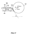
- FIG. 17
- describes a method of setting the inclination angle of the detection lever contact surface; and
- FIG. 18A and FIG. 18B
- are perspective views showing a modification of the detection mechanism.
- A roll paper printer according to a first embodiment of the invention is described below with reference to
FIG. 1 to FIG. 8 . -
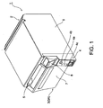
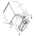
FIG. 1 is a perspective external view of a roll paper printer according to the present invention, andFIG. 2 an is perspective view showing the printer when the cover unit is open. - The
roll paper printer 1 according to this embodiment has aprinter chassis 2 with anoperable cover unit 3 attached at the front. An operating panel unit 4 is disposed at a front corner of theprinter chassis 2. Apaper exit 5 extending widthwise to the printer is formed at the top part of thecover unit 3 at the front of the printer. - The
printer chassis 2 is covered by a box-like printer case 6 that is long in the front-to-back (longitudinal) direction of the printer and is open at the front and bottom sides. Aoperable cover case 7 that defines the printer front is attached at the front of thecover unit 3. Operating an operatinglever 8 located at the operating panel unit 4 releases a cover lock not shown, thereby releasing and causing thecover unit 3 to swing forward and open by pivoting on the bottom end part of thecover unit 3. Opening thecover unit 3 opens a roll paper loading opening 9a at the front of theinternal paper compartment 9 so that apaper roll 10 can be replaced. - A
state indicator group 4a of LEDs, for example, afeed button 4b, and a power switch 4c are provided on the front of the operating panel unit 4. - As further described below, a paper amount detection mechanism for detecting when the paper roll stored inside has decreased to a predetermined size (a predetermined diameter) is also disposed inside the
paper compartment 9. When a control unit not shown disposed inside theprinter 1 detects that the paper roll has decreased to or below this predetermined amount, an indicator in thestate indicator group 4a is driven to light steadily or blink, for example, to alert the user. If theprinter 1 is connected to a terminal device not shown, a message may also be presented on the terminal device, for example. -
FIG. 3 is a schematic view of the inside of theprinter 1. Thepaper compartment 9 formed inside theprinter 1 is surrounded by acurved bottom panel 12 extending widthwise to the printer, atop panel 13 extending widthwise to the printer, andfront panel 14 extending widthwise to the printer and generally conforming to the shape of thepaper roll 10. Thepaper roll 10 is held so that it can rotate freely on thebottom panel 12 inside thepaper compartment 9 as a paper guide. - A
core hole 101 is rendered in the center of thepaper roll 10. The tape ofrecording paper 10a that is delivered from thepaper roll 10 is pulled to the front past the printing position between theplaten roller 15 and thethermal print head 16, and is discharged to the front of the printer from thepaper exit 5 disposed in front of the printing position. A scissortype cutting device 20 is disposed in front of thepaper exit 5. - The cutting
device 20 has a fixedblade 21 disposed on the printer chassis side, and amovable blade 22 and adrive mechanism 23 for the movable blade disposed on the cover unit side. The fixedblade 21 is disposed substantially horizontally widthwise to the printer with thecutting edge 21a facing forward. Themovable blade 22 is disposed substantially vertically widthwise to the printer with thecutting edge 22a facing up at a position substantially directly below thecutting edge 21 a of the fixedblade 21. When therecording paper 10a is conveyed between these cuttingedges movable blade 22, which is on the bottom, is pivoted upwards so that the cutting edges 21 a and 22a close together widthwise to the printer and cut therecording paper 10a located therebetween. -
FIG. 4 is a side view showing the mechanical part of theprinter 1 with theprinter case 6 and thecover case 7 removed.FIG. 5A and FIG. 5B are a perspective view and a side view, respectively, with one side panel removed as denoted by the imaginary line to show the internal structure.FIG. 6A and FIG. 6B are a perspective view and a side view, respectively, similar toFIG. 5 but with the cover unit open. - As shown in these figures, the
printer chassis 2 has abase panel 31 defining the printer bottom, right andleft side panels base panel 31 with a specific gap therebetween, and aback panel 30 disposed between the back of these right andleft side panels head mounting panel 34 is disposed horizontally widthwise to the printer across the gap between the top portions of theside panels thermal print head 16 is mounted at the bottom of thehead mounting panel 34 with thehead surface 16a facing down and substantially horizontal (seeFIG. 3 ). Thetop panel 13 of thepaper compartment 9 is located below the back part of thehead mounting panel 34. Thebottom panel 12 of thepaper compartment 9 is located on top of thebase panel 31. - A fixed
blade mounting plate 35 is disposed horizontally widthwise to the printer above thehead mounting panel 34. The fixedblade 21 of the cuttingdevice 20 is attached substantially horizontally and facing forward at the front bottom part of the fixedblade mounting plate 35. The fixedblade mounting plate 35 is disposed between the top edges of the right and left pivot plates 37 (only onepivot plate 37 is shown in the figures), which are located outside of theside panels pivot plates 37 can pivot (move) slightly in the longitudinal (front-to-back) direction of the printer on thebottom end portions 37a (only onebottom portion 37a is shown in the figures) of thepivot plates 37. When the cuttingdevice 20 cuts therecording paper 10a, themovable blade 22 pivots up from below while pushing the fixedblade 21 to the back so that thecutting edges recording paper 10a. Thepivot plates 37 support the fixedblade 21 so that the fixedblade 21 retracts slightly while cutting the paper. - A paper
amount detection mechanism 50 for detecting when the supply of roll paper held in thepaper compartment 9 has decreased to or below a predetermined amount is assembled to the bottom end portion on the outside of theside panel 33. - The
cover unit 3 can open to a predetermined angle to the front of the printer pivoting on support pins 41, 42 affixed at the bottom end part of theside panels printer chassis 2. Thecover unit 3 has afront panel portion 43 and narrowside panel portions front panel portion 43 perpendicularly toward the back of the printer. Themovable blade 22 and thedrive mechanism 23 of the cuttingdevice 20 are disposed at the front of thefront panel portion 43, and are covered by aprotective panel 24. The front of theprotective panel 24 is covered by the cover case 7 (seeFIG. 3 ). Theplaten roller 15 is disposed freely rotatably between theside panel portions front panel 14 of thepaper compartment 9 affixed to the back side of thefront panel portion 43 is located below theplaten roller 15. - As described above, the
front panel 14 of thepaper compartment 9, theplaten roller 15, and themovable blade 22 of the cuttingdevice 20 are mounted in thecover unit 3. Opening thecover unit 3 opens thepaper compartment 9 as shown inFIG. 2 andFIG. 5 , and opens the paper transportation path from thepaper compartment 9 past the printing position and paper cutting position to thepaper exit 5. Therefore, when a specific length ofrecording paper 10a is pulled from thepaper roll 10 inside thepaper compartment 9 and thecover unit 3 is then closed, therecording paper 10a is automatically set and threaded through the paper transportation path. -
FIG. 7A, FIG. 7B, and FIG. 7C are a partial perspective view, a plan view, and a side view of the paperamount detection mechanism 50.FIG. 8A, FIG. 8B, and FIG. 8C are a partial perspective view, a plan view, and a side view of thedetection mechanism 50 when thecover unit 3 is open. - The
detection mechanism 50 is described with reference toFIG. 4 to FIG. 8 . Thedetection mechanism 50 has adetection lever 51 attached to the outside of theside panel 33 of theprinter chassis 2. The end of thedetection lever 51 toward the back of the printer can pivot widthwise to the printer on asupport stud 52 attached to theside panel 33. Atorsion spring 52a (urging member) is disposed on thesupport stud 52, and thistorsion spring 52a constantly urges thedetection lever 51 to the inside widthwise to the printer (the projection direction). - A
detection tab 53 projecting to the inside widthwise to the printer is attached to the distal end part of thedetection lever 51. Thedetection tab 53 projects to the inside of thepaper compartment 9 through an opening not shown in theside panel 33. Thebottom panel 12 of thepaper compartment 9 is inclined slightly to the front, and as thepaper roll 10 resting thereon is used (consumed), the diameter gradually decreases and thecore hole 101 therefore gradually descends to the front. When the diameter of thepaper roll 10 has decreased to a predetermined size, thecore hole 101 of thepaper roll 10A reaches aposition 101A, i.e., the position where thedetection tab 53 protrudes. - Until the diameter of the
paper roll 10 has decreased to the predetermined size, thedetection tab 53 is held pressed against theend face 10b of thepaper roll 10 held in thepaper compartment 9. When thecore hole 101 of thepaper roll 10 has descended to a predetermined level, which is the position where thedetection tab 53 protrudes, thedetection tab 53 enters thecore hole 101. - The base end of the
detection lever 51 is linked to one switchingpart 54a of thedetection switch 54. Thedetection switch 54 is off when thedetection tab 53 contacts theend face 10b of thepaper roll 10. When thedetection tab 53 is inserted into thecore hole 101 of thepaper roll 10, thedetection lever 51 pivots and thedetection switch 54 linked to the back end of thedetection lever 51 turns off. A control unit not shown detects the output (change) from thedetection switch 54, and knows that the diameter of thepaper roll 10 has dropped to a predetermined size, there islittle recording paper 10a left, and thepaper roll 10 will soon need replacing. - The
detection mechanism 50 according to this embodiment has aretraction mechanism 55 for retracting thedetection tab 53 of thedetection lever 51 protruding into thepaper compartment 9 from thepaper compartment 9 in conjunction with the opening of thecover unit 3. - The
retraction mechanism 55 according to this embodiment has alink bar 72 that moves reciprocally between a retreated position (first position) A separated from thedetection tab 53 and an advanced position (second position) B pushing thedetection tab 53 in the retraction direction. A tension spring 67 (urging member) pulls thelink bar 72 to the retreated position A. - The
distal end part 72a of thelink bar 72 is linked to rotate freely on asupport pin 69 affixed to theside panel 45 of thecover unit 3. A longstraight slot 72b is formed in the front-to-back direction of the printer in the back portion of thelink bar 72. Aslide pin 65 affixed to theside wall part 63 of thebottom panel 12 of thepaper compartment 9 is slidably inserted into theslot 72b. Thetension spring 67 is stretched between theslide pin 65 and a position on the bottom end of theback panel 30 of theprinter chassis 2. - Opening and closing the
cover unit 3 causes thelink bar 72 to move bidirectionally longitudinally to the printer between the retreated position A (FIG. 7 ) and the advanced position B (FIG. 8 ). A wide portion is formed in the middle part of thelink bar 72, and acontact plate part 72c extending toward the bottom moves along a path past the position where thedetection tab 53 protrudes. When thelink bar 72 is in the retreated position A (when thecover unit 3 is in theclosed position 3A shown inFIG. 1 ), thecontact plate part 72c is offset to the back side of thedetection tab 53 as shown inFIG. 7B and FIG. 7C . When thelink bar 72 then moves to the advanced position B, thedetection tab 53 is pushed to the outside by thecontact plate part 72c, contacts the outside of thecontact plate part 72c, and thedetection tab 53 is thus held in the retracted position by thecontact plate part 72c. - When the
cover unit 3 closes from theopen position 3B, thelink bar 72 also returns from the advanced position B to the retreated position A, thedetection tab 53 separates from thecontact plate part 72c, and thus again protrudes into thepaper compartment 9. - The
detection tab 53 of thedetection lever 51 is thus retracted from thepaper compartment 9 in conjunction with an opening of thecover unit 3. Thedetection tab 53 is thus removed from inside thepaper compartment 9 when thepaper roll 10 is replaced, and thedetection tab 53 is therefore prevented from contacting thepaper roll 10 and interfering with its replacement. - Because the
detection tab 53 is thus retracted, there is no need to form a tapered or sloped surface on the distal end part of thedetection tab 53 to facilitate pushing thedetection tab 53 out of the way when replacing the roll paper. Furthermore, because a taper or inclined surface can be omitted, the detection precision of thedetection tab 53 can also be improved. - Note that as shown in
FIG. 7 tapers detection tab 53. Thefront taper 53a is provided to prevent interference with the edge of the opening, not shown, in theside panel 33, and theback taper 53b is provided to facilitate being pushed by thecontact plate part 72c of thelink bar 72. A taper is not formed on theoutside surfaces tapers core hole 101 of the paper roll 10 (arrow C inFIG. 5B andFIG. 7 ). Because tapers are not formed on either side in the paper detection direction, the detection precision can be improved compared with arrangements having tapers on these surfaces. - In the
paper compartment 9 of theprinter 1 according to this embodiment thebottom panel 12 changes between a substantially horizontal posture to a forward sloping posture in conjunction with an opening and closing of thecover unit 3. When thecover unit 3 opens, thebottom panel 12 slopes forward and thepaper roll 10 resting on thebottom panel 12 rolls forward due to its own weight. In this embodiment a mechanism for ejecting thepaper roll 10 includes parts (including thelink bar 72 and the tension spring 67) of theretraction mechanism 55 as further described below. - This ejection mechanism is described with reference primarily to
FIG. 3 ,FIG. 5A ,FIG. 5B ,FIG. 6A, and FIG. 6B . Thebottom panel 12 rests on thebase panel 31 so that the front end side can move circularly freely in the front-to-back direction of the printer onsupport pin 61. Slide pins 65 (only oneslide pin 65 is shown in the figures) are affixed protruding to the sides at the back ofside wall parts bottom panel 12. - Tension springs 67 (only one
tension spring 67 is shown in the figures) are stretched and attached between these slide pins 65 and a place at the bottom end of theback panel 30. These left and right tension springs 67 hold thebottom panel 12 in a substantiallyhorizontal position 12A in contact with thebase panel 31. - Identically shaped flat link bars 71 and 72 are disposed between these slide pins 65 and a vertically central part of the left and right
side panel portions cover unit 3. Thedistal end parts pins straight slots guide hole 74 is shown in the figures) formed in the left andright side panels FIG. 4 . These guide holes 74 are arcs of which the center issupport pin 61. When thebottom panel 12 pivots onsupport pin 61, the slide pins 65 move along these guide holes 74. - The operation of the ejection mechanism thus rendered in the
paper compartment 9 is described next. - When the
cover unit 3 is in the closed position, the left and right slide pins 65 of thebottom panel 12 are positioned at the front end of theslots FIG. 4 , the slide pins 65 are positioned at the bottom end of the arc-shaped guide holes 74. - When the
cover unit 3 opens, the left and right link bars 71 and 72, of which the front ends are linked to the left and rightside panel portions cover unit 3, move forward. The left and right slide pins 65 attached to thebottom panel 12 of thepaper compartment 9 are positioned at the front end of theslots bottom panel 12 does not move until the link bars 71 and 72 have moved forward a predetermined distance and the back ends of theseslots - After the slide pins 65 contact the back ends of the
slots cover unit 3 continues to open. As a result, thebottom panel 12 to which these slide pins 65 are attached can move circularly on thesupport pin 61 at the front, and thus swings forward on thesupport pin 61 in conjunction with opening thecover unit 3. - As shown in
FIG. 6 , when thecover unit 3 is in the fullyopen position 3B, thebottom panel 12 is inclined a predetermined angle in the forwardinclined position 12B. As a result, thebottom panel 12 changes from the substantiallyhorizontal position 12A to the forwardinclined position 12B in conjunction with an opening of thecover unit 3. When thepaper roll 10 is on thebottom panel 12, the weight of thepaper roll 10 causes thepaper roll 10 to roll forward on thebottom panel 12 in this forwardinclined position 12B. As a result, thepaper roll 10 having little remainingrecording paper 10a is ejected to the front as denoted by the imaginary lines inFIG. 6 . Thepaper roll 10 can therefore be easily removed from the top front of theopen cover unit 3. - After the
bottom panel 12 started to pivot, thecover unit 3 is pulled to the back by the left and right tension springs 67 by means of the intervening link bars 71 and 72. The tension of the tension springs 67 thus prevents thecover unit 3 from opening suddenly to the front when thecover unit 3 is opened, and thus prevents damage resulting from thecover unit 3 hitting the surface on which the printer is placed with great force. - When the
cover unit 3 is then closed, the link bars 71 and 72 also move to the back in conjunction with thecover unit 3 closing. The forward tension on the left and right slide pins 65 of thebottom panel 12 is thus released, and the force of the tension springs 67 returns thebottom panel 12 to the original substantiallyhorizontal position 12A. As a result, thepaper roll 10 resting on thebottom panel 12 is stored in the predetermined position. - A roll paper printer according to a second embodiment of the invention is described next with reference to
FIG. 9 to FIG. 16 . -
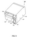
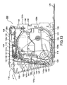
FIG. 9 is an external perspective view of the roll paper printer,FIG. 10 is a perspective view of the printer mechanism part as seen from the front left,FIG. 11 is a perspective view of the printer mechanism part as seen from the front right,FIG. 12 is a perspective view of the printer mechanism part when the cover unit is open, andFIG. 13 is a schematic diagram showing the internal arrangement of the roll paper printer. - A
printer 100 according to this embodiment has aprinter mechanism unit 200, aprinter case 102 covering substantially all of theprinter mechanism unit 200, and anoperable cover case 103 covering the front of theprinter mechanism unit 200 that is not covered by theprinter case 102. Apaper exit 108 extending widthwise to thecover case 103 is formed at the top part of thecover case 103. - The
printer case 102 covers part of the front, the top, the right and left sides, and the back of theprinter mechanism unit 200. Disposed at the front of theprinter case 102 are apower switch 104 for turning power to theprinter 100 on and off, astate indicator group 105 for reporting the operating state of theprinter 100, and afeed button 107 that is used to feed thepaper roll 106 held inside theprinter 100. - The
printer mechanism unit 200 comprises aprinter chassis 101a and anoperable cover unit 101b. Thecover unit 101 b comprises theoperable cover 109 and thecover case 103 attached to the front of thecover 109. Thecover unit 101 b is connected by a hinge at the front bottom part of theprinter mechanism unit 200, and can swing forward and open on this hinge. Operating the operatinglever 120 disposed at the front of theprinter case 102 releases a cover lock not shown and enables thecover 109 to swing on the bottom end part of thecover 109 from the closed position shown inFIG. 10 andFIG. 11 to the open position shown inFIG. 12 . When thecover 109 opens, the rollpaper loading opening 121a at the front of thepaper compartment 121 formed inside theprinter chassis 101a is opened as shown inFIG. 12 so that thepaper roll 106 can be replaced. Thepaper roll 106 is generally a tape of recording paper (thermal paper in this embodiment of the invention) wound into a roll on a core. - As shown in
FIG. 10 ,FIG. 11 , andFIG. 12 , theprinter chassis 101a has abase panel 125, right andleft side panels base panel 125, a back panel (not shown in the figure) disposed between the back of these right andleft side panels top panel 128 disposed horizontally widthwise to the printer between the top portions of theside panels - A
paper holder 129 forming the bottom and back of thepaper compartment 121 extends between the left andright side panels cover unit 101b is affixed on asupport shaft 130 between the front ends of the left andright side panels cover unit 101 b can pivot to an open position on thesupport shaft 130. - The
cover unit 101 b has afront panel portion 131 andside panel portions front panel portion 131. Apaper cutting device 134 having an internalmovable blade 133 is disposed at the top outside of thefront panel portion 131, and a fixedblade 135 is disposed above thecutting device 134 with thepaper exit 108 therebetween. The fixedblade 135 is supported by a fixed blade support frame (not shown in the figure) disposed at the top part of theprinter chassis 101a. The leading end of the recording paper from thepaper roll 106 passes between themovable blade 133 and fixedblade 135 to thepaper exit 108. To cut the recording paper, themovable blade 133 pivots upward to the fixedblade 135 and cuts the recording paper in conjunction with themovable blade 133. - A
platen roller 136 is disposed freely rotatably between the top parts of theside panel portions cover unit 101b as shown inFIG. 12 andFIG. 13 . When thecover unit 101 b is closed, athermal print head 137 is disposed above theplaten roller 136 at a position opposite theplaten roller 136 as shown inFIG. 13 , and a plurality of resistance heating elements are disposed on the bottom of thethermal print head 137. The recording paper drawn off thepaper roll 106 housed in thepaper compartment 121 is held between theplaten roller 136 and thethermal print head 137, and is conveyed to thepaper exit 108 by rotating theplaten roller 136 by means of a motor not shown. - Text and images are printed on the recording paper by heat emitted from the resistance heating elements of the
thermal print head 137 as the paper passes between theplaten roller 136 andthermal print head 137. Thethermal print head 137 is located on ahead mounting panel 138 disposed below theprinter case 102, and thishead mounting panel 138 comprises ahead support panel 139 for supporting thethermal print head 137, and aspring support panel 140 joined in unison with thehead support panel 139 by ascrew 138a. - As shown in
FIG. 13 , afirst paper guide 151 for guiding the recording paper to theplaten roller 136 is disposed below thehead mounting panel 138. Thisfirst paper guide 151 comprises acurved portion 151a of which the distal end portion curves and extends upward. Thiscurved portion 151a is proximally behind theplaten roller 136. The recording paper curves upward at thecurved portion 151a, and is then guided to theplaten roller 136. This prevents creasing the edge of the paper in case force is applied to the paper from the side. - A
front panel 141 forming the back of thecover unit 101 b is affixed inside thecover unit 101 b. Thisfront panel 141 comprises abase part 141a disposed at an angle toward the back of the printer, and acurved part 141 b continuing from thebase part 141a and curving to the back. Asecond paper guide 152 disposed at the top end of thecurved part 141 b contacts and causes the recording paper to curve when thepaper roll 106 is consumed to a size at which thepaper roll 106 does not contact thefirst paper guide 151 when the paper is conveyed. - This
second paper guide 152 is affixed so that it can pivot on asupport pin 153, and is normally urged to the back by an urging member not shown. Thissecond paper guide 152 also prevents creases in the edge of the paper. - The
paper compartment 121 is rendered between thepaper holder 129 and thefront panel 141 of thecover unit 101 b. Thepaper holder 129 comprises abottom part 129a that inclines slightly to the front, and aback part 129b that extends curving upward from the back end of thebottom part 129a. - The
paper roll 106 held in thepaper compartment 121 is delivered from the back side of the roll through thepaper exit 108 located in front of the roll, and is discharged from the front of theprinter 100. As a result, the outside of thepaper roll 106 is pushed against thefront panel 141 as the recording paper is discharged from thepaper exit 108. Regardless of the size of the diameter of the roll, thepaper roll 106 can always be supported by thebottom part 129a of thepaper holder 129 and thecover unit 101 b. - A
first roller 142 extending widthwise to the printer is disposed at thebase part 141a of thefront panel 141 midway between the top and bottom of thebase part 141 a, and substantially in the center in this embodiment. Asecond roller 143 also extending widthwise to the printer is disposed below thefirst roller 142 at the bottom end part of thebase part 141a in this embodiment. More specifically,openings base part 141 a of thefront panel 141, and the shaft parts of these first andsecond rollers openings second rollers base part 141 a of thefront panel 141. - As shown in
FIG. 13 , when the outer diameter of thepaper roll 106 is large, specifically when the diameter of thepaper roll 106 is between a maximum diameter of approximately 83 mm and approximately 50 mm in this embodiment, thefirst roller 142 contacts thepaper roll 106 and reduces the rolling resistance of thepaper roll 106 rolling inside thepaper compartment 121. - When the
paper roll 106 is consumed so that the diameter of thepaper roll 106 becomes small, thesecond roller 143 contacts the outside of thepaper roll 106 and likewise reduces the rolling resistance of thepaper roll 106 rolling inside thepaper compartment 121. - That the diameter of the
paper roll 106 is small means in this embodiment that the outside of thepaper roll 106 does not contact thefirst roller 142. More specifically, the diameter of thepaper roll 106 is less than approximately 50 mm. These first andsecond rollers paper roll 106 rolls smoothly regardless of the paper roll diameter as the size of thepaper roll 106 gradually becomes smaller. These first andsecond rollers paper roll 106 as the paper roll diameter decreases and the outside of thepaper roll 106 does not directly contact thefront panel 141 of thecover unit 101 b. - A paper amount detection mechanism (near-end detection mechanism) 160 for detecting when the size of the
paper roll 106 in thepaper compartment 121 has decreased to a predetermined size is disposed as shown inFIG. 11 at theright side panel 127 of theprinter chassis 101a. Thedetection mechanism 160 has a detection lever further described below that is pressed against an end face of thepaper roll 106, which is pressed to thefront panel 141 of thecover unit 101b of thepaper compartment 121 during paper transportation. The near-end of thepaper roll 106 is detected when the detection lever separates from the outer edge of the end face of thepaper roll 106 to the side toward the back of the printer (away from the outer edge). - As shown in
FIG. 14A to FIG. 14C , thedetection mechanism 160 comprises aframe 161 fixed to the right side panel 132, adetection lever 163 that is attached to theframe 161 freely pivotally on asupport pin 162 and is pressed to the end face of thepaper roll 106 in thepaper compartment 121, apressure spring 164 for urging thedetection lever 163, and adetection switch 165 that operates according to the pivoting action of thedetection lever 163. - The
detection lever 163 comprises a taperedsurface 163a formed on the front end, acontact surface 163b formed on the side that is pressed against the end face of the roll paper, arocker part 163c formed on the back end part for operating thedetection switch 165, and aspring catch 163d for holding one end of thepressure spring 164. Thecontact surface 163b is tapered so that the width of thedetection lever 163 increases to the front. In other words, thecontact surface 163b tapers to the back of the printer. - The
frame 161 comprises asupport part 161a that curves in a basic U-shape and supports thedetection lever 163, and aspring catch 161b formed by bending one end of thesupport part 161a substantially perpendicularly for holding the other end of thepressure spring 164. - The detection operation of this
detection mechanism 160 is described next with reference toFIG. 15A andFIG. 15B . When the outer diameter of thepaper roll 106 is large, thecontact surface 163b of thedetection lever 163 is pressed against theend face 106a of thepaper roll 106 as shown inFIG. 15A . Therocker part 163c of thedetection lever 163 touches thedetection switch 165 at this time, and the size of the roll paper is thus known to be greater than a predetermined size. - When the diameter of the
paper roll 106 becomes small, the force of thepressure spring 164 causes thedetection lever 163 to separate from the outer edge of theend face 106a of thepaper roll 106 and move toward the back of the printer (to the outside of the outer edge), and project to the inside of thepaper compartment 121 as shown inFIG. 15B . As a result, therocker part 163c of thedetection lever 163 separates from thedetection switch 165. This causes thedetection switch 165 to output a near-end state detection signal, that is, an electric signal indicating that the size of thepaper roll 106 has decreased to a predetermined size or less. - The function of the
contact surface 163b (the taper to the back of the printer) formed on thedetection lever 163 is described next. - This embodiment has a retraction mechanism for retracting the
detection lever 163 to the outside of thepaper compartment 121 in conjunction with the opening action of thecover unit 101 b when thecover unit 101 b is opened. Thecontact surface 163b functions as a surface engaging a movingplate 167 of the retraction mechanism. -
FIG. 16 shows the retraction mechanism, which is described next with reference toFIG. 12 andFIG. 16 . Theright side panel 127 of theprinter chassis 101a and theside panel 132b of thecover unit 101b are linked by this movingplate 167. When thecover unit 101b opens, the movingplate 167 slides forward (as indicated by arrow Y in the figure) along theright side panel 127. Accompanying this motion, thedistal end 167a of the movingplate 167 contacts and pushes thecontact surface 163b of thedetection lever 163 to the outside of thepaper compartment 121. As a result, when thecover unit 101b opens, thedetection lever 163 is retracted to the outside of thepaper compartment 121. - The
detection lever 163 therefore does not protrude into thepaper compartment 121 when thecover unit 101 b is open, and thepaper roll 106 can be easily replaced or thepaper roll 106 can be easily removed and inserted. - When the
paper roll 106 moves to the back inside thepaper compartment 121 and thedetection lever 163 separates from theend face 106a of the paper roll 106 (so that thedetection lever 163 protrudes), thecontact surface 163b functions as a guide surface for returning thedetection lever 163 to the position pressing against theend face 106a. More specifically, when thepaper roll 106 moves forward inside thepaper compartment 121 from the back, thecontact surface 163b of thedetection lever 163 is pushed smoothly out by the outer edge portion of thepaper roll 106. As a result, thecontact surface 163b can again contact theend face 106a of thepaper roll 106. This means that even if vibration, for example, causes thepaper roll 106 to roll forward and back inside thepaper compartment 121, the return of thepaper roll 106 to the predetermined position enables continuing to detect when thepaper roll 106 has decreased to the predetermined small size. - The near-end of the
paper roll 106 is detected when thedetection lever 163 separates from theend face 106a of thepaper roll 106. However, because thepaper roll 106 may simply be moving inside thepaper compartment 121, the near-end detection is preferably confirmed only after the near-end signal is output continuously for a predetermined time (such as 10 seconds). - As described above, the
detection lever 163 is retracted from thepaper compartment 121 when thecover unit 101b opens, and closing thecover unit 101 b causes thedetection lever 163 to protrude into thepaper compartment 121. In this case, thedetection lever 163 protrudes into thepaper compartment 121 before thepaper roll 106 is loaded into thepaper compartment 121 when thecover unit 101b is closed, and thepaper roll 106 is held between thedetection lever 163 andcover unit 101b. - More specifically, if the
cover unit 101b is closed when the diameter of thepaper roll 106 is small (such as when the outer diameter is approximately 50 mm) and thepaper roll 106 contacts the first roller 142 (FIG. 13 ), thedetection lever 163 protrudes into thepaper compartment 121 before thepaper roll 106 rolls into thepaper compartment 121. As a result, thepaper roll 106 may become stuck between thedetection lever 163 and thefront panel 141 of thecover unit 101b. - However, a
tapered surface 163a that rises to the top of the printer is formed at the front part of thedetection lever 163 in this embodiment. The slope α of this taperedsurface 163a is set so that if asmall diameter roll 106 is between thetapered surface 163a and thefront panel 141 of thecover unit 101 b, thepaper roll 106 can easily ride over the taperedsurface 163a. - More specifically, as shown in
FIG. 17 , when a force F is applied horizontally to the taperedsurface 163a by thepaper roll 106, this force F has force component F·cosα acting in the direction of the slope of the taperedsurface 163a, and force component F·sinα acting perpendicularly to the slope. If µ is the static friction coefficient of the taperedsurface 163a, slope α of the taperedsurface 163a is set so that the equation F·cosα > µF·sinα is true. In other words, slope α is set to an angle < tan-1(1/µ). - When thus comprised, the
paper roll 106 slides along the upward-facing taperedsurface 163a and is stored in thepaper compartment 121 when thecover unit 101b closes even if thedetection lever 163 protrudes into thepaper compartment 121 so that thepaper roll 106 is between thedetection lever 163 and thefront panel 141 of thecover unit 101b before thepaper roll 106 is stored in thepaper compartment 121. - As described above, a
printer 100 according to this embodiment has a retraction mechanism that moves thedetection lever 163 in conjunction with an opening and a closing of thecover unit 101 b. When thecover unit 101 b opens, thedetection lever 163 retracts to the outside of thepaper compartment 121 as thecover unit 101 b opens. Thedetection lever 163 of thedetection mechanism 160 therefore does not protrude into thepaper compartment 121 when thecover unit 101b is open, and thepaper roll 106 can be easily replaced, removed, or loaded. - During paper transportation, the
paper roll 106 is pressed toward thecover unit 101b in this embodiment, and the near-end of thepaper roll 106 can be detected by means of thedetection lever 163 that is pushed against the end face of thepaper roll 106. As a result, thepaper roll 106 can be held so that it does not move to the front of thepaper compartment 121 without providing a channel in the bottom of thepaper compartment 121 as is required by the prior art. The size of theprinter 100 can therefore be reduced by an amount corresponding to the savings achieved by omitting this channel, and the near-end of thepaper roll 106 can yet be reliably detected. - Furthermore, when the
detection lever 163 of thedetection mechanism 160 is pressed against theend face 106a of thepaper roll 106 and thepaper roll 106 is consumed so that the outer diameter of thepaper roll 106 is small, thedetection lever 163 separates from the outside edge of theend face 106a of thepaper roll 106 toward the back of the printer and protrudes into thepaper compartment 121. Compared with an arrangement in which the detection lever is inserted into a hole in the center of thepaper roll 106 core, the arrangement of this embodiment enables detecting the near-end of thepaper roll 106 more easily. - In addition, a
tapered surface 163a is formed on the front end part of thedetection lever 163, and the slope α of the taperedsurface 163a is set to an angle enabling thepaper roll 106 to move smoothly over the taperedsurface 163a and be stored in thepaper compartment 121 when thepaper roll 106 is between thetapered surface 163a andcover unit 101 b. As a result, thepaper roll 106 travels over the taperedsurface 163a of thedetection lever 163 and is stored in thepaper compartment 121 even if thedetection lever 163 protrudes into thepaper compartment 121 and thepaper roll 106 is disposed between thedetection lever 163 and thecover unit 101 b before thepaper roll 106 is stored into thepaper compartment 121 when closing thecover unit 101 b. The problem of thepaper roll 106 being locked between thetapered surface 163a and thecover unit 101 b is thus prevented. - A
contact surface 163b that tapers to the back of the printer is rendered on the side portion of thedetection lever 163 so that thedetection lever 163 again contacts theend face 106a of thepaper roll 106 if thepaper roll 106 moves to the back inside thepaper compartment 121, thedetection lever 163 separates from theend face 106a of thepaper roll 106, and thepaper roll 106 then moves to the front of thepaper compartment 121 again. Thepaper roll 106 therefore returns to the predetermined position even if thepaper roll 106 moves inside thepaper compartment 121 due to vibration, for example, and detecting the near-end of thepaper roll 106 can continue. - A modification of the paper
amount detection mechanism 160 is described next with reference toFIG. 18A andFIG. 18B .FIG. 18A is a perspective view from the top of thisdetection mechanism 160A, andFIG. 18B is a perspective view of thedetection lever 163A. Note that parts with the same or similar function in the figures are identified by the same reference numerals, and further description thereof is omitted. - This
detection mechanism 160A differs from thedetection mechanism 160 described above in that aninclined guide surface 163e facing the printer top and the inside side is rendered on thetop part 163f of thedetection lever 163A. Thisguide surface 163e is formed on the side of avertical extension 163g of taperedsurface 163a of thedetection lever 163A, and thisguide surface 163e has a slope declining to thecontact surface 163b. - As described above, the
detection lever 163 may protrude to the inside of thepaper compartment 121 before thepaper roll 106 is stored in thepaper compartment 121 when thecover unit 101b closes. Depending on the outer diameter of thepaper roll 106, thepaper roll 106 could ride up on thetop part 163f of thedetection lever 163A when thecover unit 101 b is closed quickly. - A tapered
guide surface 163e is therefore formed on thetop part 163f in this embodiment. Because the outer circumferential edge of thepaper roll 106 contacts this taperedguide surface 163e from above, the weight and the corresponding acceleration of gravity of thepaper roll 106 cause thedetection lever 163A to be pushed smoothly to the outside of thepaper compartment 121. - As a result, the
paper roll 106 moves on thepaper holder 129, and thecontact surface 163b touches theend face 106a of thepaper roll 106. Therefore, when thepaper roll 106 is small and thecover unit 101 b is closed quickly with force so that thepaper roll 106 rides up onto thedetection lever 163A, thedetection lever 163A is pushed by thepaper roll 106 in contact with the taperedguide surface 163e, and is held pressed against theend face 106a of thepaper roll 106. Detecting the near-end of the roll paper can therefore continue. - This aspect of the invention describes rendering a tapered
guide surface 163e on an extension of the taperedsurface 163a, but the tapered guide surface can be rendered on all of thetop part 163f, or tapered guide ribs can be rendered on thetop part 163f. - The invention has been described using by way of example a roll paper printer having a thermal print head. It will be obvious to one with ordinary skill in the art that the invention can also be applied to roll paper printers using other types of print heads, including, for example, inkjet heads or dot impact heads.
Claims (11)
- A roll paper printer comprising:a paper compartment (9, 121) having a bottom surface adapted to hold a roll of recording paper so that the paper roll (10, 10A, 106) is able to roll;a cover unit (3, 101b) for opening and closing a paper loading opening (9a, 121a) to the paper compartment (9, 121); anda detection mechanism (50, 160, 160A) for detecting the amount of roll paper on said roll comprising a detection lever (51, 163, 163A) arranged to be movable in a protruding direction to protrude into the paper compartment (9, 121) and a retracting direction to be retracted from the paper compartment (9, 121), and an urging member (52a, 164) for urging the detection lever (51, 163, 163A) in the protruding direction,wherein the detection lever (51, 163, 163A) is adapted to contact the paper roll (10, 10A, 106) in a first state in which it protrudes into the paper compartment (9, 121) and the outer diameter of the paper roll (10, 10A, 106) is above a predetermined value, and to separate from the paper roll (10, 10A, 106) and be pushed further in the protruding direction in a second state in which the outer diameter of the paper roll (10, 10A, 106) in the paper compartment (9, 121) is equal to or below the predetermined value; characterized bya retraction mechanism (55) linked to the cover unit (3, 101b) and responsive to an opening movement of the cover unit (3, 101 b) for retracting the detection lever (51, 163, 163A) in the retracting direction from the paper compartment (9, 121) against the urging force of the urging member (52a, 164).
- The printer of claim 1, wherein the retraction mechanism (55) comprises a moving element (72, 167) adapted to move between a first position separated from the detection lever (51, 163, 163A), and a second position pushing the detection lever (51, 163, 163A) in the retraction direction.
- The printer of claim 2, wherein the retraction mechanism (55) comprises an urging member (67) for urging the moving element (72) toward the first position.
- The printer of any one of claims 1 to 3, wherein, in said first state, the detection lever (51, 163, 163A) is pressed against an end face (10b, 106a) of the paper roll (10, 10A, 106) in the paper compartment (9, 121), and, in said second state, the detection lever (51, 163, 163A) separates from that end face (10b, 106a) and is pushed in the protruding direction.
- The printer of claim 4, wherein the paper roll (10, 10A) has a core having a core hole (101) that extends in the axial direction therethrough and is positioned in the center of said end face (10b), and, in said second state, the detection lever (51) separates from the inner circumferential edge of said end face (10b) of the roll paper to enter the core hole (101).
- The printer of claim 4, wherein the detection lever (51, 163, 163A) is arranged to separate, in said second state, from the outer circumferential edge of said end face (10b, 106a) and be pushed further in the protruding direction.
- The printer of claim 5 or 6, wherein:the paper compartment (9, 121) stores the paper roll (10, 10A, 106) with the rotary axis of the paper roll (10, 10A, 106) aligned widthwise to the printer;the protruding direction and the retraction direction extend widthwise to the printer;the paper loading opening (9a, 121a) is formed at a front side of the printer; andthe cover unit (3, 101b) can open to the printer's front by pivoting on a bottom end part of the cover unit (3; 101b), and has a platen (15, 136) defining the printing position of the print head attached to a top end portion of the cover unit (3, 101b).
- The printer of claim 6, wherein the paper roll (106) stored in the paper compartment (9, 121) is pressed to the cover unit (101b) side while recording paper from the paper roll is advanced toward the printing position.
- The printer of claim 8, wherein:an upward-facing tapered surface (163a) facing the printer top and rising toward the printer top is formed at a front end part of the detection lever (163, 163A) facing the cover unit (101b); andthe slope of the upward-facing tapered surface (163a) is set so that pushing the cover unit (101b) in the closing direction enables a paper roll (10A, 106) disposed between the upward-facing tapered surface (163a) and the cover unit (101b) to move over the upward-facing tapered surface (163a) to the back side of the detection lever (163, 163A).
- The printer of claim 8, wherein:a back-facing tapered surface (163b) facing the printer back is formed at a side part of the detection lever (163, 163A) facing the paper compartment (121); andthe back-facing tapered surface (163b) can contact the outer circumferential edge part of the end face (106a) of a paper roll (10A, 106) moving from the back of the detection lever (163, 163A) to the front.
- The printer of claim 8, wherein:an inward-facing tapered guide surface (163e) facing the inside widthwise to the printer is formed at a top part of the detection lever (163A); andthis tapered guide surface can contact the outer circumferential edge of the end face (106a) of a paper roll (106) moving down from the top of the detection lever (163A).
Applications Claiming Priority (2)
| Application Number | Priority Date | Filing Date | Title |
|---|---|---|---|
| JP2005230398A JP4696768B2 (en) | 2005-08-09 | 2005-08-09 | Roll paper printer |
| JP2005355738A JP4835137B2 (en) | 2005-12-09 | 2005-12-09 | Recording device |
Publications (2)
| Publication Number | Publication Date |
|---|---|
| EP1752304A1 EP1752304A1 (en) | 2007-02-14 |
| EP1752304B1 true EP1752304B1 (en) | 2008-03-26 |
Family
ID=37102532
Family Applications (1)
| Application Number | Title | Priority Date | Filing Date |
|---|---|---|---|
| EP06016238A Expired - Fee Related EP1752304B1 (en) | 2005-08-09 | 2006-08-03 | Roll paper printer |
Country Status (3)
| Country | Link |
|---|---|
| US (1) | US7553098B2 (en) |
| EP (1) | EP1752304B1 (en) |
| DE (1) | DE602006000808T2 (en) |
Families Citing this family (31)
| Publication number | Priority date | Publication date | Assignee | Title |
|---|---|---|---|---|
| US7878724B2 (en) * | 2005-12-27 | 2011-02-01 | Seiko Epson Corporation | Printer |
| JP5068609B2 (en) * | 2006-10-20 | 2012-11-07 | 富士通コンポーネント株式会社 | Printer device |
| US7887005B2 (en) | 2007-09-12 | 2011-02-15 | Innovia Intellectual Properties, Llc | Easy-load household automatic paper towel dispenser |
| US7549814B1 (en) | 2007-12-18 | 2009-06-23 | International Business Machines Corporation | Compact low paper sensor mechanism |
| JP4655148B2 (en) * | 2008-12-26 | 2011-03-23 | ソニー株式会社 | Paper width detecting device and image forming apparatus |
| JP5017309B2 (en) * | 2009-03-30 | 2012-09-05 | シチズンホールディングス株式会社 | Printer |
| JP2010235226A (en) * | 2009-03-30 | 2010-10-21 | Citizen Holdings Co Ltd | Near end detecting device of rolled recording medium, and printer |
| WO2010141931A2 (en) * | 2009-06-06 | 2010-12-09 | Innovia Intellectual Properties, Llc | Automatic paper towel dispenser apparatus |
| JP5459541B2 (en) * | 2009-11-17 | 2014-04-02 | 株式会社リコー | Sheet material supply apparatus and image forming apparatus |
| CN101722745B (en) * | 2009-12-17 | 2013-04-24 | 山东新北洋信息技术股份有限公司 | Paper accommodating device and printer comprising same |
| JP5543222B2 (en) * | 2010-01-05 | 2014-07-09 | シチズンホールディングス株式会社 | Printer device |
| JP2012184055A (en) * | 2011-03-03 | 2012-09-27 | Toshiba Tec Corp | Remaining amount detector for roll paper, and printer |
| KR101432362B1 (en) * | 2011-06-29 | 2014-08-20 | 후지쯔 콤포넌트 가부시끼가이샤 | Printer apparatus |
| US8974052B2 (en) | 2011-08-30 | 2015-03-10 | Brother Kogyo Kabushiki Kaisha | Printer |
| JP5576345B2 (en) * | 2011-09-30 | 2014-08-20 | 東芝テック株式会社 | Paper storage device and printer having the same |
| US8931970B1 (en) * | 2012-02-08 | 2015-01-13 | Pyramid Group, Inc. | Ticket printer |
| CN110027931B (en) * | 2012-12-17 | 2021-01-19 | 精工爱普生株式会社 | Conveying device |
| JP6120061B2 (en) * | 2013-03-07 | 2017-04-26 | ブラザー工業株式会社 | Printing device |
| US10602887B2 (en) | 2013-08-23 | 2020-03-31 | Gpcp Ip Holdings Llc | Towel dispensers |
| US9596964B1 (en) | 2013-08-23 | 2017-03-21 | Innovia Intellectual Properties, Llc | Wall mounted towel dispensers |
| US9642503B1 (en) | 2013-08-25 | 2017-05-09 | Innovia Intellectual Properties, Llc | Portable, vertically oriented automatic towel dispenser apparatus |
| JP6257981B2 (en) * | 2013-09-24 | 2018-01-10 | 富士通コンポーネント株式会社 | Near-end detection device, printer |
| US9213309B2 (en) | 2013-10-31 | 2015-12-15 | Brother Kogyo Kabushiki Kaisha | Image forming apparatus having image forming unit |
| US9207628B2 (en) | 2013-11-15 | 2015-12-08 | Brother Kogyo Kabushiki Kaisha | Image forming apparatus provided with structure for receiving liquid |
| JP2015096917A (en) | 2013-11-15 | 2015-05-21 | ブラザー工業株式会社 | Image forming apparatus |
| JP6229459B2 (en) | 2013-11-28 | 2017-11-15 | ブラザー工業株式会社 | Image forming apparatus |
| JP2015102828A (en) * | 2013-11-28 | 2015-06-04 | ブラザー工業株式会社 | Image forming apparatus |
| US9483014B2 (en) | 2013-11-29 | 2016-11-01 | Brother Kogyo Kabushiki Kaisha | Image forming apparatus having panel unit |
| DE102014106148A1 (en) * | 2014-04-30 | 2015-11-05 | Metsä Tissue Oyj | Dispensing device for dispensing a web-shaped surface product with a pivotable conveyor unit |
| CN108474701B (en) * | 2016-01-25 | 2020-08-07 | 三菱电机株式会社 | Load detector |
| CN113666167A (en) * | 2021-07-14 | 2021-11-19 | 金陵科技学院 | Monitoring devices is used in weaving with safeguard function |
Family Cites Families (16)
| Publication number | Priority date | Publication date | Assignee | Title |
|---|---|---|---|---|
| JPS5751255Y2 (en) * | 1977-03-24 | 1982-11-09 | ||
| JP2705890B2 (en) | 1993-10-21 | 1998-01-28 | 富士通アイソテック株式会社 | Roll paper limit remaining detector |
| JPH07272120A (en) | 1994-03-29 | 1995-10-20 | Toshiba Corp | Receipt issuing device |
| JPH0834554A (en) | 1994-07-22 | 1996-02-06 | Graphtec Corp | Method and device for detecting remaining quantity of roll paper |
| WO1996041039A1 (en) * | 1995-06-07 | 1996-12-19 | Cominco Ltd. | Redox control in the electrodeposition of metals |
| US6118469A (en) * | 1995-11-21 | 2000-09-12 | Seiko Epson Corporation | Thermal printer |
| DE69702152T2 (en) * | 1996-03-06 | 2001-02-15 | Seiko Epson Corp | Paper end detection device |
| JP3536842B2 (en) | 1996-03-06 | 2004-06-14 | セイコーエプソン株式会社 | Printer |
| JP3491435B2 (en) | 1996-03-26 | 2004-01-26 | セイコーエプソン株式会社 | Printer |
| JPH11130310A (en) | 1997-10-31 | 1999-05-18 | Toshiba Tec Corp | Paper detecting device |
| JP4261686B2 (en) * | 1999-06-25 | 2009-04-30 | シチズンホールディングス株式会社 | Roll paper remaining amount detecting means and printer provided with this roll paper remaining amount detecting means |
| JP3679672B2 (en) * | 2000-01-31 | 2005-08-03 | セイコーインスツル株式会社 | Near end detection device for roll paper |
| US6629796B2 (en) * | 2000-04-12 | 2003-10-07 | Seiko Epson Corporation | Printer |
| KR100354072B1 (en) | 2000-07-11 | 2002-09-27 | 삼성전자 주식회사 | Low Paper Detecting Appratus for Printer |
| EP1172319B9 (en) * | 2000-07-11 | 2006-10-18 | Samsung Electronics Co., Ltd. | Apparatus of a printer for detecting termination of printing medium |
| JP2002234223A (en) * | 2001-02-09 | 2002-08-20 | Star Micronics Co Ltd | Printer |
-
2006
- 2006-08-03 DE DE602006000808T patent/DE602006000808T2/en active Active
- 2006-08-03 EP EP06016238A patent/EP1752304B1/en not_active Expired - Fee Related
- 2006-08-09 US US11/502,031 patent/US7553098B2/en not_active Expired - Fee Related
Also Published As
| Publication number | Publication date |
|---|---|
| US7553098B2 (en) | 2009-06-30 |
| US20070036604A1 (en) | 2007-02-15 |
| DE602006000808D1 (en) | 2008-05-08 |
| EP1752304A1 (en) | 2007-02-14 |
| DE602006000808T2 (en) | 2009-04-30 |
Similar Documents
| Publication | Publication Date | Title |
|---|---|---|
| EP1752304B1 (en) | Roll paper printer | |
| US7731437B2 (en) | Paper cutting device and printer | |
| US9815309B2 (en) | Cassette for label printer | |
| EP2080626B1 (en) | Thermal printer and printing device | |
| EP1616708B1 (en) | Printer | |
| CN100475545C (en) | Roll paper printer | |
| US7011463B2 (en) | Printer | |
| US8430504B2 (en) | Printer opening and closing mechanism which prevents interference of the platen and the inkjet head | |
| CN110549751B (en) | Printing apparatus | |
| JP4830416B2 (en) | Roll paper printer | |
| US8602670B2 (en) | Printer cutter with paper exit having a notch | |
| US8840330B2 (en) | Cutter and printer with cutter | |
| US7625147B2 (en) | Printer | |
| KR100294115B1 (en) | Recording apparatus | |
| US20090085282A1 (en) | Continuous sheet processing apparatus | |
| KR100798173B1 (en) | Roll paper printer | |
| CN105408120B (en) | Label machine | |
| JP3904316B2 (en) | Cutting device | |
| JP4802612B2 (en) | Recording device | |
| JP2007076164A (en) | Recorder | |
| AU2012241088B2 (en) | Label printer |
Legal Events
| Date | Code | Title | Description |
|---|---|---|---|
| PUAI | Public reference made under article 153(3) epc to a published international application that has entered the european phase |
Free format text: ORIGINAL CODE: 0009012 |
|
| AK | Designated contracting states |
Kind code of ref document: A1 Designated state(s): AT BE BG CH CY CZ DE DK EE ES FI FR GB GR HU IE IS IT LI LT LU LV MC NL PL PT RO SE SI SK TR |
|
| AX | Request for extension of the european patent |
Extension state: AL BA HR MK YU |
|
| 17P | Request for examination filed |
Effective date: 20070627 |
|
| GRAP | Despatch of communication of intention to grant a patent |
Free format text: ORIGINAL CODE: EPIDOSNIGR1 |
|
| AKX | Designation fees paid |
Designated state(s): DE FR GB IT |
|
| GRAS | Grant fee paid |
Free format text: ORIGINAL CODE: EPIDOSNIGR3 |
|
| GRAA | (expected) grant |
Free format text: ORIGINAL CODE: 0009210 |
|
| AK | Designated contracting states |
Kind code of ref document: B1 Designated state(s): DE FR GB IT |
|
| REG | Reference to a national code |
Ref country code: GB Ref legal event code: FG4D |
|
| REF | Corresponds to: |
Ref document number: 602006000808 Country of ref document: DE Date of ref document: 20080508 Kind code of ref document: P |
|
| ET | Fr: translation filed | ||
| PLBE | No opposition filed within time limit |
Free format text: ORIGINAL CODE: 0009261 |
|
| STAA | Information on the status of an ep patent application or granted ep patent |
Free format text: STATUS: NO OPPOSITION FILED WITHIN TIME LIMIT |
|
| 26N | No opposition filed |
Effective date: 20081230 |
|
| PG25 | Lapsed in a contracting state [announced via postgrant information from national office to epo] |
Ref country code: IT Free format text: LAPSE BECAUSE OF FAILURE TO SUBMIT A TRANSLATION OF THE DESCRIPTION OR TO PAY THE FEE WITHIN THE PRESCRIBED TIME-LIMIT Effective date: 20080326 |
|
| REG | Reference to a national code |
Ref country code: FR Ref legal event code: PLFP Year of fee payment: 11 |
|
| REG | Reference to a national code |
Ref country code: FR Ref legal event code: PLFP Year of fee payment: 12 |
|
| REG | Reference to a national code |
Ref country code: FR Ref legal event code: PLFP Year of fee payment: 13 |
|
| PGFP | Annual fee paid to national office [announced via postgrant information from national office to epo] |
Ref country code: DE Payment date: 20200722 Year of fee payment: 15 Ref country code: FR Payment date: 20200715 Year of fee payment: 15 Ref country code: GB Payment date: 20200722 Year of fee payment: 15 |
|
| REG | Reference to a national code |
Ref country code: DE Ref legal event code: R119 Ref document number: 602006000808 Country of ref document: DE |
|
| GBPC | Gb: european patent ceased through non-payment of renewal fee |
Effective date: 20210803 |
|
| PG25 | Lapsed in a contracting state [announced via postgrant information from national office to epo] |
Ref country code: GB Free format text: LAPSE BECAUSE OF NON-PAYMENT OF DUE FEES Effective date: 20210803 Ref country code: FR Free format text: LAPSE BECAUSE OF NON-PAYMENT OF DUE FEES Effective date: 20210831 Ref country code: DE Free format text: LAPSE BECAUSE OF NON-PAYMENT OF DUE FEES Effective date: 20220301 |