EP1063076A1 - Wide-mouthed container bottom molding method using stretch blow molding - Google Patents
Wide-mouthed container bottom molding method using stretch blow molding Download PDFInfo
- Publication number
- EP1063076A1 EP1063076A1 EP99961455A EP99961455A EP1063076A1 EP 1063076 A1 EP1063076 A1 EP 1063076A1 EP 99961455 A EP99961455 A EP 99961455A EP 99961455 A EP99961455 A EP 99961455A EP 1063076 A1 EP1063076 A1 EP 1063076A1
- Authority
- EP
- European Patent Office
- Prior art keywords
- mold
- bottom portion
- cavity
- stretching
- preform
- Prior art date
- Legal status (The legal status is an assumption and is not a legal conclusion. Google has not performed a legal analysis and makes no representation as to the accuracy of the status listed.)
- Withdrawn
Links
Images


Classifications
-
- B—PERFORMING OPERATIONS; TRANSPORTING
- B29—WORKING OF PLASTICS; WORKING OF SUBSTANCES IN A PLASTIC STATE IN GENERAL
- B29C—SHAPING OR JOINING OF PLASTICS; SHAPING OF MATERIAL IN A PLASTIC STATE, NOT OTHERWISE PROVIDED FOR; AFTER-TREATMENT OF THE SHAPED PRODUCTS, e.g. REPAIRING
- B29C51/00—Shaping by thermoforming, i.e. shaping sheets or sheet like preforms after heating, e.g. shaping sheets in matched moulds or by deep-drawing; Apparatus therefor
- B29C51/04—Combined thermoforming and prestretching, e.g. biaxial stretching
-
- B—PERFORMING OPERATIONS; TRANSPORTING
- B29—WORKING OF PLASTICS; WORKING OF SUBSTANCES IN A PLASTIC STATE IN GENERAL
- B29C—SHAPING OR JOINING OF PLASTICS; SHAPING OF MATERIAL IN A PLASTIC STATE, NOT OTHERWISE PROVIDED FOR; AFTER-TREATMENT OF THE SHAPED PRODUCTS, e.g. REPAIRING
- B29C49/00—Blow-moulding, i.e. blowing a preform or parison to a desired shape within a mould; Apparatus therefor
- B29C49/08—Biaxial stretching during blow-moulding
- B29C49/10—Biaxial stretching during blow-moulding using mechanical means for prestretching
- B29C49/12—Stretching rods
-
- B—PERFORMING OPERATIONS; TRANSPORTING
- B29—WORKING OF PLASTICS; WORKING OF SUBSTANCES IN A PLASTIC STATE IN GENERAL
- B29C—SHAPING OR JOINING OF PLASTICS; SHAPING OF MATERIAL IN A PLASTIC STATE, NOT OTHERWISE PROVIDED FOR; AFTER-TREATMENT OF THE SHAPED PRODUCTS, e.g. REPAIRING
- B29C49/00—Blow-moulding, i.e. blowing a preform or parison to a desired shape within a mould; Apparatus therefor
- B29C49/42—Component parts, details or accessories; Auxiliary operations
- B29C49/48—Moulds
- B29C49/54—Moulds for undercut articles
- B29C49/541—Moulds for undercut articles having a recessed undersurface
-
- B—PERFORMING OPERATIONS; TRANSPORTING
- B29—WORKING OF PLASTICS; WORKING OF SUBSTANCES IN A PLASTIC STATE IN GENERAL
- B29C—SHAPING OR JOINING OF PLASTICS; SHAPING OF MATERIAL IN A PLASTIC STATE, NOT OTHERWISE PROVIDED FOR; AFTER-TREATMENT OF THE SHAPED PRODUCTS, e.g. REPAIRING
- B29C49/00—Blow-moulding, i.e. blowing a preform or parison to a desired shape within a mould; Apparatus therefor
- B29C49/42—Component parts, details or accessories; Auxiliary operations
- B29C49/48—Moulds
- B29C49/4802—Moulds with means for locally compressing part(s) of the parison in the main blowing cavity
- B29C2049/4807—Moulds with means for locally compressing part(s) of the parison in the main blowing cavity by movable mould parts in the mould halves
-
- B—PERFORMING OPERATIONS; TRANSPORTING
- B29—WORKING OF PLASTICS; WORKING OF SUBSTANCES IN A PLASTIC STATE IN GENERAL
- B29C—SHAPING OR JOINING OF PLASTICS; SHAPING OF MATERIAL IN A PLASTIC STATE, NOT OTHERWISE PROVIDED FOR; AFTER-TREATMENT OF THE SHAPED PRODUCTS, e.g. REPAIRING
- B29C49/00—Blow-moulding, i.e. blowing a preform or parison to a desired shape within a mould; Apparatus therefor
- B29C49/42—Component parts, details or accessories; Auxiliary operations
- B29C49/48—Moulds
- B29C2049/4856—Mounting, exchanging or centering moulds or parts thereof
- B29C2049/4858—Exchanging mould parts, e.g. for changing the mould size or geometry for making different products in the same mould
-
- B—PERFORMING OPERATIONS; TRANSPORTING
- B29—WORKING OF PLASTICS; WORKING OF SUBSTANCES IN A PLASTIC STATE IN GENERAL
- B29C—SHAPING OR JOINING OF PLASTICS; SHAPING OF MATERIAL IN A PLASTIC STATE, NOT OTHERWISE PROVIDED FOR; AFTER-TREATMENT OF THE SHAPED PRODUCTS, e.g. REPAIRING
- B29C2791/00—Shaping characteristics in general
- B29C2791/004—Shaping under special conditions
- B29C2791/007—Using fluid under pressure
-
- B—PERFORMING OPERATIONS; TRANSPORTING
- B29—WORKING OF PLASTICS; WORKING OF SUBSTANCES IN A PLASTIC STATE IN GENERAL
- B29C—SHAPING OR JOINING OF PLASTICS; SHAPING OF MATERIAL IN A PLASTIC STATE, NOT OTHERWISE PROVIDED FOR; AFTER-TREATMENT OF THE SHAPED PRODUCTS, e.g. REPAIRING
- B29C2949/00—Indexing scheme relating to blow-moulding
- B29C2949/07—Preforms or parisons characterised by their configuration
- B29C2949/0715—Preforms or parisons characterised by their configuration the preform having one end closed
-
- B—PERFORMING OPERATIONS; TRANSPORTING
- B29—WORKING OF PLASTICS; WORKING OF SUBSTANCES IN A PLASTIC STATE IN GENERAL
- B29C—SHAPING OR JOINING OF PLASTICS; SHAPING OF MATERIAL IN A PLASTIC STATE, NOT OTHERWISE PROVIDED FOR; AFTER-TREATMENT OF THE SHAPED PRODUCTS, e.g. REPAIRING
- B29C2949/00—Indexing scheme relating to blow-moulding
- B29C2949/07—Preforms or parisons characterised by their configuration
- B29C2949/072—Preforms or parisons characterised by their configuration having variable wall thickness
-
- B—PERFORMING OPERATIONS; TRANSPORTING
- B29—WORKING OF PLASTICS; WORKING OF SUBSTANCES IN A PLASTIC STATE IN GENERAL
- B29C—SHAPING OR JOINING OF PLASTICS; SHAPING OF MATERIAL IN A PLASTIC STATE, NOT OTHERWISE PROVIDED FOR; AFTER-TREATMENT OF THE SHAPED PRODUCTS, e.g. REPAIRING
- B29C2949/00—Indexing scheme relating to blow-moulding
- B29C2949/07—Preforms or parisons characterised by their configuration
- B29C2949/081—Specified dimensions, e.g. values or ranges
- B29C2949/0811—Wall thickness
- B29C2949/0817—Wall thickness of the body
-
- B—PERFORMING OPERATIONS; TRANSPORTING
- B29—WORKING OF PLASTICS; WORKING OF SUBSTANCES IN A PLASTIC STATE IN GENERAL
- B29C—SHAPING OR JOINING OF PLASTICS; SHAPING OF MATERIAL IN A PLASTIC STATE, NOT OTHERWISE PROVIDED FOR; AFTER-TREATMENT OF THE SHAPED PRODUCTS, e.g. REPAIRING
- B29C2949/00—Indexing scheme relating to blow-moulding
- B29C2949/07—Preforms or parisons characterised by their configuration
- B29C2949/081—Specified dimensions, e.g. values or ranges
- B29C2949/0811—Wall thickness
- B29C2949/0818—Wall thickness of the bottom
-
- B—PERFORMING OPERATIONS; TRANSPORTING
- B29—WORKING OF PLASTICS; WORKING OF SUBSTANCES IN A PLASTIC STATE IN GENERAL
- B29C—SHAPING OR JOINING OF PLASTICS; SHAPING OF MATERIAL IN A PLASTIC STATE, NOT OTHERWISE PROVIDED FOR; AFTER-TREATMENT OF THE SHAPED PRODUCTS, e.g. REPAIRING
- B29C49/00—Blow-moulding, i.e. blowing a preform or parison to a desired shape within a mould; Apparatus therefor
- B29C49/02—Combined blow-moulding and manufacture of the preform or the parison
- B29C49/06—Injection blow-moulding
-
- B—PERFORMING OPERATIONS; TRANSPORTING
- B29—WORKING OF PLASTICS; WORKING OF SUBSTANCES IN A PLASTIC STATE IN GENERAL
- B29L—INDEXING SCHEME ASSOCIATED WITH SUBCLASS B29C, RELATING TO PARTICULAR ARTICLES
- B29L2031/00—Other particular articles
- B29L2031/712—Containers; Packaging elements or accessories, Packages
- B29L2031/7132—Bowls, Cups, Glasses
-
- B—PERFORMING OPERATIONS; TRANSPORTING
- B29—WORKING OF PLASTICS; WORKING OF SUBSTANCES IN A PLASTIC STATE IN GENERAL
- B29L—INDEXING SCHEME ASSOCIATED WITH SUBCLASS B29C, RELATING TO PARTICULAR ARTICLES
- B29L2031/00—Other particular articles
- B29L2031/712—Containers; Packaging elements or accessories, Packages
- B29L2031/7158—Bottles
- B29L2031/716—Bottles of the wide mouth type, i.e. the diameters of the bottle opening and its body are substantially identical
Abstract
Description
- The present invention relates to a method for molding a bottom portion of a wide-mouthed container by stretch blow molding, and in particular, relates to a method for molding a bottom portion of a synthetic resin-made wide-mouthed container which is manufactured by stretch blow molding a wide-mouthed preform having been injection molded.
- In a wide-mouthed container formed to have a thin body portion and bottom portion by stretch blow molding, there is not much difference between the outer diameter of its mouth portion and the outer diameter of its body portion. Therefore, the radial stretching ratio is small compared to a narrow-mouthed container such as a bottle. Thus, the stretching ratio of the body portion is increased by forming a preform into a truncated cone shape to increase the radial stretching ratio, or by forming a preform into a container-like (cup-like) shape to stretch the body portion as long as possible in the axial direction.
- Stretching of the above-mentioned truncated cone shaped preform is conducted by abutting a pressing member on the tip end of a stretching rod to the center of the bottom portion. Stretching of a container shaped preform is conducted by abutting a disk-like formed pressing member to a corner portion formed on the border between the bottom edge of the body portion and the bottom portion.
- A problem when stretching by pressing against the central portion of the bottom portion is that the stretching stress caused by extension of the stretching rod concentrates in the central portion, and if the resin temperature of the central portion is about the same resin temperature as the body portion, the pressing member on the tip end of the stretching rod is pierced through the central portion. In order to prevent this, the central portion of the bottom portion is made thinner than other portions to keep the resin temperature low so that the central portion of the bottom portion can sufficiently resist the pressing force. However, the central portion is not stretched compared to other portions and stretching in the radial direction by air blow is not sufficient, and thus, this portion tends to remain as a lenticular thickened portion in the center of the bottom portion of the wide-mouthed container. Since this central portion is hardly stretched, there is a problem in that it is inferior in impact strength, and inferior in heat resistance than other portions having been sufficiently stretched.
- A problem when stretching by pressing a disk-like pressing member to a corner portion on the periphery of the bottom portion is that the bottom portion is hardly stretched, and the bottom portion of the wide-mouthed container is left in its injection molded state. Such a stretching method may apply to polypropylene or polyethylene in which the resin itself has flexibility; but it is difficult to apply this method to polyester resins, such as polyethylene terephthalate (PET) or polyethylene naphthalate (PEN), where various physical properties are enhanced by biaxial orientation.
- Most of the wide-mouthed containers are used as packing containers for processed foods having viscosity such as butter, jam, peanut butter and honey; and such processed foods are filled into the wide-mouthed container in a heated condition. Therefore, insufficient stretching of the bottom portion results in heat deformation upon filling, and this impairs product image even if this deformation occurs in the bottom portion.
- Further, if the container is sealed after heat-filling, there frequently occurs deformation in the body portion by decompression which occurs as the content cools.
- This deformation by decompression can be made inconspicuous by forming the body portion of the wide-mouthed bottle into a polyhedral shape. However, since it is not possible to adopt this to a wide-mouthed container having a cylindrical body portion, the shape of the wide-mouthed container being heat-filled is of a polyhedron, which almost always caused trouble in label attachment compared to cylindrical containers, and which is not good in visibility of the content.
- There have been made attempts to form the bottom portion of the wide-mouthed container so that it easily deforms upon decompression. For example, the body portion is prevented from deforming by decompression by forming the bottom portion into a bellows-like form with a projecting and depressing surface formed by a plurality of concentric circles so that the bottom portion deforms largely in a concaving manner inwardly from the periphery of the bottom portion. Thus, heat-filling is possible even to a cylindrical wide-mouthed container.
- However, as described previously, in stretch blow molding, the bottom portion of the preform is the most difficult portion to be stretched. The thickness distribution of the bottom portion tends to become uneven compared to the body portion; and it is difficult to transfer the projecting and depressing surface, which is formed on a mold surface of a bottom mold, to the bottom portion exactly according to the mold surface even when a high blow-air pressure is employed; and in the bellows formed on the bottom surface, the bending portion comes to have a thick, uneven section. Thus, deformation upon decompression is poor, and is not enough to prevent decompression deformation of the body portion.
- The present invention has been contrived in order to solve the conventional problems in molding a bottom portion of the above-described wide-mouthed container, and an object of the present invention is to provide a method for molding a bottom portion of a wide-mouthed container by stretch blow molding which makes it possible to mold, according to stretching the body portion and the bottom portion respectively and separately and stepwise, the bottom portion of the preform thin like its body portion in a state in which the thickness distribution is controlled, and, which also makes it possible to form the bottom portion into a bellows-like form with an acute projecting and depressing surface formed by a plurality of concentric circles according to the usage of the wide-mouthed container.
- In order to achieve the above-described object, the present invention provides a method for molding a bottom portion of a wide-mouthed container by stretch blow molding, the method comprising the steps of injection-molding a preform which has a thick, short-cylindrical body portion and a thin, plate-like bottom portion which continues from the bottom end of the body portion, and in which the border therebetween is integrally formed as a corner portion; employing, as a blow mold for stretch blow molding the preform into a wide-mouthed container, a blow mold comprising a bottom mold which can proceed and retreat within a cavity; employing, as a stretching rod, a stretching rod comprising both a core member which pressures a central portion of the bottom portion, and a skirt member which is positioned in the periphery of the core member and which pressures the corner portion; carrying out stretching by precedingly stretching either one of the respective body portion or the bottom portion of the preform by means of the stretching rod until the body portion reaches the bottom edge of the cavity, and the bottom portion protrudes below the bottom edge of the cavity and comes to a position above the bottom mold having been ducked beneath a bottom surface of the cavity; then protruding the bottom mold into the cavity in which the preform is in an air-blown state, to further stretch the bottom portion having been primarily stretched upwards from the bottom edge of the cavity; and forming a thin bottom portion of a container with an even thickness distribution.
- In the method for molding a bottom portion according to the present invention, the longitudinal stretching of the bottom portion and body portion of the preform is separately conducted by the core member and the skirt member; and after primary stretching by the stretching rod, the bottom portion is again stretched by the bottom mold in order to form a bottom portion of a wide-mouthed container. Thus, the stretching of the bottom portion is reliably conducted and the thickness distribution of the bottom portion is controlled compared to the conventional case in which the center of the bottom portion is pressed and stretching of the bottom portion and the body portion is conducted simultaneously.
- A different aspect of the present invention is such that: as for the bottom mold of the blow mold, there is used a bottom mold in which the mold surface facing the cavity has an acute projecting and depressing surface formed by a plurality of concentric circles; as for the stretching rod, there is used a stretching rod in that the skirt member is provided around the core member so that it is fixed to the stretching rod with a play existing therebetween, and is constantly pressured downwards by means of a spring member; the bottom mold is protruded into the cavity in a state in which the lower end of the body portion of the preform is pushed to the bottom edge of the cavity by means of the skirt member; the bottom portion having been primarily stretched is further stretched so that it is pushed back upwards from the bottom edge of the cavity; and thus the bottom portion is formed into a bellows-like form with an acute projecting and depressing surface formed by a plurality of concentric circles by means of the bottom mold.
- In such a method for molding a bottom portion, the longitudinal stretching of the body portion of the preform is conducted by the skirt member. Further, stretching of the bottom surface, which is by the stretching rod being abutted to the central portion of the bottom portion, is conducted in a state in which the corner portion of the periphery of the bottom surface is supported by the skirt member. Thus, the bottom surface is stretched to be thinner than is conventionally possible. Further, the molding of the bottom surface is conducted by pressing the bottom mold into the cavity after thinly stretching, and pushing the mold surface to the thin bottom surface. Thus, even when the mold surface of the bottom mold has an acute projecting and depressing surface, transferring of such projecting and depressing surface to the bottom surface is reliably conducted, making it possible to mold a bellows-like bottom surface which prevents deformation of the body portion by stretching deformation into the container caused by decompression.
- The preform of the present invention is such that: it is made of a thermoplastic resin which can be stretch blow molded; the bottom portion is comprised of a central portion to which the core member of the stretching rod abuts, and an intermediate portion between the central portion and the corner portion to which the skirt member abuts; and the intermediate portion is formed so that it is made thicker than the central portion by means of a protuberance portion of a concentric circle so that it is streched before the central portion.
- In a preform with such a structure, the intermediate portion of the bottom portion is formed thicker than the central portion.
Thus, because of the difference in thickness, in comparing the amount of heat the resin of both the portions possesses, the amount is larger in the intermediate portion than in the central portion. When the central portion is pushed by the core member, the intermediate portion precedingly stretches and the protuberance portion is thinly stretched. Thus, the thickness between the central portion is eliminated, whereafter the whole bottom portion is stretched until the skirt member reaches the corner portion. - In the prior art, in order to prevent the bottom portion from being pierced due to the concentration of stress to the central portion during stretching, the bottom portion is set to such a preform temperature that the entire bottom portion is made thinner than the body portion to set the temperature thereof lower than that of the body portion to stretch the bottom portion after the body portion has been stretched thinner than the bottom portion. As a result, the thickness distribution of the bottom becomes un-uniform. However, this problem can be easily solved and it makes it possible to mold a bottom portion corresponding to the use of the wide-mouthed container.
- Further, the present invention is such that: the core member and the skirt member of the stretching rod are integrally formed; the core member is protrudingly formed at a required length compared to the skirt member so that stretching of the bottom portion of the preform precedes; and, after the bottom portion is extended by the stretching rod, the skirt member is abutted to the corner portion in the border between the body portion and the bottom portion in order to stretch the body portion down to the bottom edge of the cavity.
- By adopting such a stretching rod, it is possible to stretch the body portion and the bottom portion stepwise by means of extension of the stretching rod. Even when stretching the body portion and the bottom portion separately at a sequential timing, it is possible to simplify the stretching phase in that it is possible to conduct both operations sequentially by one extension operation of the stretching rod.
- The stretching rod of the present invention is such that: it is insertingly provided in a blow core in a vertically movable manner; by fitting the blow core and a lip mold which sandwiches and holds a mouth portion of the preform, the core member on the tip end of the stretching rod and the skirt member are placed in an inserted position within the preform; and, by extension of the stretching rod, either the core member or the skirt member abuts against either the bottom portion or the corner portion of the preform to carry out stretching.
-
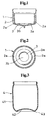
- Fig. 1 is a longitudinal sectional view of a preform used in the method for molding a bottom portion of a wide-mouthed container by stretch blow molding according to the present invention;
- Fig. 2 is a planar view of a preform used in the method for molding a bottom portion of a wide-mouthed container by stretch blow molding according to the present invention;
- Fig. 3 is a longitudinal sectional view of a wide-mouthed container of a first embodiment molded to have a thin bottom portion according to the present invention;
- Fig. 4 is a longitudinal sectional view of a wide-mouthed container of a second embodiment wherein the bottom portion is formed into a bellows-like form with a projecting and depressing surface of concentric circles according to the present invention;
- Fig. 5 is a longitudinal sectional view showing a state in which the wide-mouthed container of the second embodiment according to the present invention is deformed by decompression;
- Fig. 6 is a longitudinal sectional view showing a state inside a mold before stretch blow molding the wide-mouthed container of the first embodiment;
- Fig. 7 is a longitudinal sectional view showing a state in which the bottom portion is precedingly stretched according to the first embodiment;
- Fig. 8 is a longitudinal sectional view showing a stretching state of a body portion after the bottom portion of the first embodiment has been stretched;
- Fig. 9 is a sectional view taken upon completion of the wide-mouthed container of the first embodiment by protruding the bottom mold in the cavity in an air-blown state;
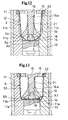
- Fig. 10 is a longitudinal sectional view showing a state inside a mold before stretch blow molding the wide-mouthed container of the second embodiment;
- Fig. 11 is a horizontal sectional view of the cavity taken along the A-A line in Fig. 10;
- Fig. 12 is a longitudinal sectional view showing a state in which the body portion is first stretched and then the bottom portion is stretched thereafter according to the second embodiment; and
- Fog. 13 is a sectional view taken upon completion of the wide-mouthed container of the second embodiment having its bottom portion formed into a bellows-like shape by protruding the bottom mold in the cavity in an air-blown state.
-
- The present invention will hereinafter be explained with reference to the accompanying drawings, to which the present invention shall not be limited. Fig. 1 and Fig. 2 show a first embodiment of a preform which can be manufactured by adopting the method of the present invention.
- The
preform 1 is made of a thermoplastic resin such as polyethylene terephthalate (PET), polyethylene naphthalate (PEN), polyethylene (PE), polypropylene (PP) and polycarbonate (PC). - The
preform 1 made of such resin is composed of abody portion 2 and abottom portion 3. Thebody portion 2 is of a short cylindrical shape and is made thick by injection molding. Thebottom portion 3 is made to be thin and plate-like, and continues from the bottom end of the body portion. The border therebetween is integrally formed as acorner portion 2a. - The
bottom portion 3 of thepreform 1 is composed of acentral portion 3b and anintermediate portion 3a between thecentral portion 3b and thecorner portion 2a. Theintermediate portion 3a is designed so that: it is made thicker than thecentral portion 3b by means of a protuberance portion of a concentric circle; because of the difference between the thickness of both portions, when comparing the heat possessed thereby, the amount is larger in theintermediate portion 3a than in thecentral portion 3b; and, theintermediate portion 3a is precedingly stretched and then the whole bottom portion is stretched. - The thickness in the respective portions of such a
preform 1, if the molding material is polyethylene terephthalate, for example the body portion is 3.0 mm, the central portion of the bottom portion is 1.5 mm and the intermediate portion is 2.5 to 3.0 mm; and it is in a heated state upon blow molding. Stretch blow molding is conducted when the surface temperature of the preform is in a range of from 90 to 110 °C. The air pressure upon air-blow is, for example, 18 to 25 kgf/cm2. - Fig. 3 shows a wide-
mouthed container 4 of the first embodiment. It is a wide-mouthed container 4 which is manufactured by stretch blow molding the above-describedpreform 1, and which bottom portion has a general structure. The wide-mouthed container 4 is molded according to a molding method shown in Fig. 6 through Fig. 9. Accordingly, not only thebody portion 41, but the thickness distribution from thebottom portion periphery 43 to thebottom portion 42 which is formed like a dome inwardly facing the container is even; and thus, the conventional phenomenon, in which the central portion becomes lenticularly thick, is resolved. Since the whole bottom portion is stretch-molded to be thin and approximately uniform, impact strength and heat resistance are enhanced. - Fig. 4 shows a wide-
mouthed container 5 of a second embodiment in which the structure of the bottom portion is bellows-like. The wide-mouthed container 5 is molded according to a molding method shown in Fig. 10 through Fig. 13. Accordingly, along with thebody portion 51, the thickness of thebottom portion 52 is also formed thin and uniform. Thus, transferring of the mold surface with an acute projecting and depressing surface formed by a plurality of concentric circles to the bottom surface is reliably conducted, and thebottom surface 54 of thebottom portion 52 is formed to be bellows-like by concentric circles from thebottom portion periphery 53. As described above, when the container is sealed, as the inner portion is decompressed, the bellows-likebottom surface 54 deforms easily and thebottom portion 52 is pulled into the container, and thus, it is possible to prevent the deformation by decompression of thebody portion 51, as shown in Fig. 5. - Fig. 6 and after show the method of molding a bottom portion according to the present invention. Fig. 6 through Fig. 9 orderly explain a molding process of the first embodiment, and Fig. 10 through Fig. 13 orderly explain a molding process of the second embodiment, respectively. In each of the molding processes, the same portion is explained with the same reference number. [Molding of bottom portion of wide-
mouthed container 4 of the first embodiment (Fig. 6 through Fig. 9)] - In the figures,
reference numeral 11 denotes a blow mold for a wide-mouthed container, which mold is of a pair ofmold halves bottom mold 13 which proceeds and retreats against acavity 12. Themold surface 14 of thebottom mold 13 facing thecavity 12 is spherical, and by raising thebottom mold 13, it is placed in a protruding position from thebottom edge 11b of the cavity into thecavity 12. When lowered, the mold surface is in a ducking position within a hole in the bottom surface of the cavity, and above the mold surface, an insertion space is formed for the bottom portion of the preform having been primarily stretched. -
Reference numeral 15 designates a blow core, and a stretchingrod 16 is inserted therein in an ascentable-and-descentable manner with agap 17 for air blow provided therearound. At the tip end of the stretchingrod 16, there is integrally formed acore member 18 which presses thecentral portion 3b of the bottom portion of thepreform 1, and askirt member 19 with a large diameter which presses thecorner portion 2a. In order for the stretching of thebottom portion 3 to precede, thecore member 18 is protrudingly formed at a required length compared to theskirt member 19. - The
preform 1 is in a state in which, except for its mouth portion, the whole preform possesses a necessary amount of heat in a condition for stretch blow; and it is carried into the openedblow mold 11 by holding the mouth portion with alip mold 22. Then the preform is set in the upper center of thecavity 12 by closure of theblow mold 11. Further, theblow core 15 is hermetically inserted from above into the mouth portion; thereby the open-mouth periphery of thepreform 1 is sandwiched and held with thelip mold 22, and thecore member 18 at the tip end of the stretchingrod 16 and theskirt member 19 are placed within thepreform 1. - Here, the
mold surface 14 of thebottom mold 13 is ducked beneath the bottom surface of the cavity so that the bottom surface of the preform is positioned further beneath thebottom edge 11b of the cavity and so that thebody portion 2 can be stretched to thebottom edge 11b of the cavity. - After such operations, the stretching
rod 16 is extended by a drive means such as an air cylinder. Then, only thecore member 18 presses thecentral portion 3b of the bottom portion of thepreform 1, and stretching is conducted to a condition shown in Fig. 7. At this stretching step, theskirt member 19 is located above thecore member 18, and thus thecorner portion 2a is not abutted; and only thebottom portion 3 is precedingly stretched to a predetermined dimension. - In the
bottom portion 3 in which thecentral portion 3b is thinner than theintermediate portion 3a, because of this difference in thickness, the amount of heat possessed by theintermediate portion 3a is larger than the central portion. Therefore, when thecentral portion 3b is pressed by thecore member 18, theintermediate portion 3a is precedingly stretched and the protuberance portion is thinly extended, and thus, the difference in thickness between thecentral portion 3b is eliminated. Then, thecentral portion 3b is also stretched. When the wholebottom portion 3 is stretched to a set dimension, theskirt member 19 reaches and abuts thecorner portion 2a, as shown in Fig. 7, and thereby, the periphery of the bottom portion is evenly pressed to cause stretching of thebody portion 2. - After the
skirt member 19 abuts thecorner portion 2a, thebottom portion 3 is not stretched beyond the set dimension, and it is pushed downwards towards the bottom portion of the cavity along with the stretching of thebody portion 2 by means of theskirt member 19. Stretching is continued until theskirt member 16 reaches thebottom edge 11a of the cavity. - At the point in which the
skirt member 16 reaches thebottom edge 11b of the cavity, thecorner portion 2a is also thinly pressed and stretched, and thebottom portion 3 is received by the insertion space above themold surface 14 of thebottom mold 13 ducking beneath the bottom surface of the cavity. Along with this stretching operation, air is blown to the preform from theair blow gap 17 of theblow core 15, and thebody portion 2 is axially stretched while expanding radially and is pressed against the peripheral wall of the cavity, thus forming thebody portion 41 of the wide-mouthed container 4. Further, thebottom portion 3 expands within the insertion space and is made thin. (See Fig. 8.) - After completing stretching by extending the stretching
rod 16, the stretchingrod 16 is freed. Then thebottom mold 13 is raised under pressure by blown-air, and thebottom portion 3 is pushed up by themold surface 14. Then, since thebody portion 41 is in contact with the peripheral wall surface of the cavity and cooling and solidification is already proceeding, thebottom portion 3 is pressingly extended by themold surface 14 from the lower side of thebottom edge 11b of the cavity which forms a border so that it bends upwards and thus, is subjected to secondary stretching. - Because of positional relations, stretching caused by the
mold surface 14 tends to occur from thecentral portion 3b which remains thicker than the other portions, and further, the stretching spreads towards the circumference. When the rising of thebottom mold 13 is completed, there is molded a thin, dome-like bottom portion 42 which takes abottom edge 43 as a border between thebody portion 41. Accordingly, there is completed the wide-mouthed container 4 of the first embodiment having abottom portion 42 which is thin like thebody portion 41, and being entirely even in thickness distribution. (See Fig. 9.) - The difference between the molding method of the present embodiment and the molding method for the wide-
mouthed container 4 is that, in order to form the bottom surface of a wide-mouthed container 5 into a bellows-like form, thecore member 18 and theskirt member 19 of the stretchingrod 16 are structured so that they are relatively movable, and that themold surface 14 of thebottom mold 13 is formed with a projecting and depressing surface. - As shown in Fig. 10, in the stretching
rod 16 adopted in the molding method according to the present embodiment, the tip end portion is formed on thenarrow shaft portion 16a, and askirt member 19 is fit, along with acoil spring 21 positioned thereabove, to thenarrow shaft portion 16a so that there is play therebetween. On the tip end of thenarrow shaft portion 16a, there is attached acore member 18 which has a larger diameter than thenarrow shaft portion 16a and which has a stepped portion in its upper edge. The stepped portion of thecore member 18 latches with theskirt member 19, and prevents theskirt member 19 from falling off from thenarrow shaft portion 16a. Thecoil spring 21 constantly pressures theskirt member 19 downwards. - On the
mold surface 14 of thebottom mold 13 facing thecavity 12, there is formed an acute projecting and depressing surface formed by a plurality of concentric circles. - Similar to the case in molding the wide-
mouthed container 4, molding of the bottom portion of the wide-mouthed container 5 by means ablow mold 11 which comprises such a stretchingrod 16 andbottom mold 15 can be conducted by holding the mouth portion of thepreform 1 with the above-describedlip mold 22, and setting thepreform 1 into the central portion of the openedblow mold 11 in a general manner. - After setting, the
blow core 15 is inserted into the mouth portion from above to thereby sandwich and hold the preform 20 with thelip mold 22, and thecore member 18 and theskirt member 19 of the stretchingrod 16 are abutted to the predetermined points, and then the mold is closed in a state which prevents the preform from contracting. (See Fig. 10.) - After closing the mold, the stretching
rod 16 is extended by a drive such as an air cylinder, and the preform 20 is stretched longitudinally. This stretching is conducted both by theskirt member 19, which is constantly pressured and supported downwards by thecoil spring 21, and thecore member 18; however, theskirt member 19 stops when it reaches thebottom edge 11b of the cavity. - However, working against the
coil spring 21, the stretchingrod 16 stretches the bottom surface until thecore member 18 reaches themold surface 14 of thebottom mold 13. Thus, since the stretching of the bottom surface is conducted stepwise in a state wherein the periphery of thebottom portion 3 is supported by theskirt member 19 being pressured by thecompressed spring member 21 and by thebottom edge 11b of the cavity, it is stretched to be thinner compared to conventional cases. (See Fig. 12.) - The longitudinal stretching of the
preform 1 is conducted by blowing air into the preform from the air blow,gap 17 of theblow core 15. After thepreform 1 fully expands within the cavity by air-blow and is formed into the wide-mouthed container 5, the driving force of the stretchingrod 16 is released, thebottom mold 13 is raised and moved, and themold surface 14 of the upper portion of the bottom mold is pressured into the cavity, while maintaining the air-blow condition. - The stretching
rod 16, which is in a free condition because the driving force has been released, rises along with thecore member 18 by mean of the restoring force of thecompressed spring member 21 to a point where thecore member 18 is received by theskirt member 19. Because of the rise of thebottom mold 13, thecore member 18 is pushed back upwards; and thus, thebottom portion 3 which has been primarily stretched is pushed inside the cavity by themold surface 14 in a state wherein thebottom portion 3 is supported to thebottom edge 11b of the cavity by theskirt member 19. - Accordingly, the
peripheral edge 53 of the bottom portion of the wide-mouthed container 5 is molded, and simultaneously, the projecting and depressing surface of themold surface 14 is strongly engaged into the thinly formedbottom surface 52 of the wide-mouthed container 5 by means of both the pressuring force of thebottom mold 13 and the inner pressure by blown-air. As a result, the acute projecting and depressing surface which is the same as themold surface 14 is transferred to thebottom surface 52, and the bottom surface comes to have a bellows-like form of concentric circles. (See Fig, 13.) - In the molding method of the present invention, the axial stretching of the
body portion 2 of thepreform 1 is conducted by theskirt member 19, and stretching of thecentral portion 3b of thebottom portion 3 is conducted by the stretchingrod 16 in a state in which the periphery of thebottom portion 3 is supported by theskirt member 19. Further, the projecting and depressing surface formed on themold surface 14 is transferred to the thinly stretchedbottom portion 3 of thebottom portion 3 of the wide-mouthed container 5 by pushing in themold surface 14. Thus, it is possible to reliably transfer even an acute projecting and depressing surface to the bottom surface, which had been deemed difficult to transfer, and it is possible to easily mold a wide-mouthed container 5 in which the bottom surface is of a bellows-like form with an acute projecting and depressing surface formed by a plurality of concentric circles, and in which the structure of the bottom portion deforms into the container by decompression.
Claims (5)
- A method for molding a bottom portion of a wide-mouthed container by stretch blow molding, the method comprising the steps of injection-molding a preform which has a thick, short-cylindrical body portion and a thin, plate-like bottom portion which continues from the bottom end of the body portion, and in which the border therebetween is integrally formed as a corner portion; employing, as a blow mold for stretch blow molding the preform into a wide-mouthed container, a blow mold comprising a bottom mold which can proceed and retreat within a cavity; employing, as a stretching rod, a stretching rod comprising both a core member which pressures a central portion of the bottom portion, and a skirt member which is positioned in the periphery of the core member and which pressures the corner portion; carrying out stretching by precedingly stretching either one of the respective body portion or the bottom portion of the preform by means of the stretching rod until the body portion reaches the bottom edge of the cavity, and the bottom portion protrudes below the bottom edge of the cavity and comes to a position above the bottom mold having been ducked beneath a bottom surface of the cavity; then protruding the bottom mold into the cavity in which the preform is in an air-blown state, to further stretch the bottom portion having been primarily stretched upwards from the bottom edge of the cavity; and forming a thin bottom portion of a container with an even thickness distribution.
- A method for molding a bottom portion of a wide-mouthed container by stretch blow molding according to claim 1 characterized in that: as for the bottom mold of the blow mold, there is used a bottom mold in which the mold surface facing the cavity has an acute projecting and depressing surface formed by a plurality of concentric circles; as for the stretching rod, there is used a stretching rod in that the skirt member is provided around the core member so that it is fixed to the stretching rod with a play existing therebetween, and is constantly pressured downwards by means of a spring member; the bottom mold is protruded into the cavity in a state in which the lower end of the body portion of the preform is pushed to the bottom edge of the cavity by means of the skirt member; the bottom portion having been primarily stretched is further stretched so that it is pushed back upwards from the bottom edge of the cavity; and thus the bottom portion is formed into a bellows-like form with an acute projecting and depressing surface formed by a plurality of concentric circles by means of the bottom mold.
- A method for molding a bottom portion of a wide-mouthed container by stretch blow molding according to claims 1 or claim 2 characterized in that: the preform is made of a thermoplastic resin which can be stretch blow molded; the bottom portion is comprised of a central portion to which the core member of the stretching rod abuts, and an intermediate portion between the central portion and the corner portion to which the skirt member abuts; and the intermediate portion is formed so that it is made thicker than the central portion by means of a protuberance portion of a concentric circle so that it is stretched before the central portion.
- A method for molding a bottom portion of a wide-mouthed container by stretch blow molding according to claims 1 or claim 2 characterized in that: the core member and the skirt member of the stretching rod are integrally formed; the core member is protrudingly formed at a required length compared to the skirt meter so that stretching of the bottom portion precedes; and, after the bottom portion is extended by the stretching rod, the skirt member is abutted to the corner portion in the border between the body portion and the bottom portion in order to stretch the body portion down to the bottom edge of the cavity.
- A method for molding a bottom portion of a wide-mouthed container by stretch blow molding according to claims 1 or claim 2 characterized in that: the stretching rod is insertingly provided in a blow core in a vertically movable manner; by fitting the blow core and a lip mold which sandwiches and holds a mouth portion of the preform, the core member on the tip end of the stretching rod and the skirt member are placed in an inserted position within the preform; and, by extension of the stretching rod, either the core member or the skirt member abuts against either the bottom portion or the corner portion of the preform to carry out stretching.
Applications Claiming Priority (3)
| Application Number | Priority Date | Filing Date | Title |
|---|---|---|---|
| JP37386198 | 1998-12-28 | ||
| JP37386198 | 1998-12-28 | ||
| PCT/JP1999/007378 WO2000038902A1 (en) | 1998-12-28 | 1999-12-28 | Wide-mouthed container bottom molding method using stretch blow molding |
Publications (2)
| Publication Number | Publication Date |
|---|---|
| EP1063076A1 true EP1063076A1 (en) | 2000-12-27 |
| EP1063076A4 EP1063076A4 (en) | 2002-03-13 |
Family
ID=18502886
Family Applications (1)
| Application Number | Title | Priority Date | Filing Date |
|---|---|---|---|
| EP99961455A Withdrawn EP1063076A4 (en) | 1998-12-28 | 1999-12-28 | Wide-mouthed container bottom molding method using stretch blow molding |
Country Status (3)
| Country | Link |
|---|---|
| EP (1) | EP1063076A4 (en) |
| AU (1) | AU1803600A (en) |
| WO (1) | WO2000038902A1 (en) |
Cited By (38)
| Publication number | Priority date | Publication date | Assignee | Title |
|---|---|---|---|---|
| WO2006113428A2 (en) * | 2005-04-15 | 2006-10-26 | Graham Packaging Company, L.P. | Method for manufacturing blow molded containers, a base assembly for forming the containers and such a container |
| WO2007109022A3 (en) * | 2006-03-15 | 2007-11-22 | Graham Packaging Co | Container and method for blowmolding a base in a partial vacuum pressure reduction setup |
| US7726106B2 (en) | 2003-07-30 | 2010-06-01 | Graham Packaging Co | Container handling system |
| WO2010077517A1 (en) * | 2008-12-08 | 2010-07-08 | Graham Packaging Company, L.P. | Method of making plastic container having a deep-inset base |
| EP2242635A2 (en) * | 2008-02-07 | 2010-10-27 | Amcor Limited | Flex ring base |
| US20100301058A1 (en) * | 2006-04-07 | 2010-12-02 | Gregory Trude | System and Method for Forming a Container Having a Grip Region |
| US7900425B2 (en) | 2005-10-14 | 2011-03-08 | Graham Packaging Company, L.P. | Method for handling a hot-filled container having a moveable portion to reduce a portion of a vacuum created therein |
| US7926243B2 (en) | 2009-01-06 | 2011-04-19 | Graham Packaging Company, L.P. | Method and system for handling containers |
| US7980404B2 (en) | 2001-04-19 | 2011-07-19 | Graham Packaging Company, L.P. | Multi-functional base for a plastic, wide-mouth, blow-molded container |
| EP2356032A1 (en) * | 2008-12-08 | 2011-08-17 | Graham Packaging Company, L.P. | Plastic container having a deep-inset base |
| US8011166B2 (en) | 2004-03-11 | 2011-09-06 | Graham Packaging Company L.P. | System for conveying odd-shaped containers |
| US8075833B2 (en) * | 2005-04-15 | 2011-12-13 | Graham Packaging Company L.P. | Method and apparatus for manufacturing blow molded containers |
| US8127955B2 (en) | 2000-08-31 | 2012-03-06 | John Denner | Container structure for removal of vacuum pressure |
| WO2012156614A1 (en) * | 2011-05-19 | 2012-11-22 | Sidel Participations | Method for the stretch-blowing of a container, comprising a retraction of the stretch rod during a boxing operation |
| TWI391231B (en) * | 2005-04-15 | 2013-04-01 | Graham Packaging Co | System and method for manufacturing blow molded containers having optimal plastic distribution |
| US8584879B2 (en) | 2000-08-31 | 2013-11-19 | Co2Pac Limited | Plastic container having a deep-set invertible base and related methods |
| US8627944B2 (en) | 2008-07-23 | 2014-01-14 | Graham Packaging Company L.P. | System, apparatus, and method for conveying a plurality of containers |
| US8720163B2 (en) | 2002-09-30 | 2014-05-13 | Co2 Pac Limited | System for processing a pressure reinforced plastic container |
| US8747727B2 (en) | 2006-04-07 | 2014-06-10 | Graham Packaging Company L.P. | Method of forming container |
| US8919587B2 (en) | 2011-10-03 | 2014-12-30 | Graham Packaging Company, L.P. | Plastic container with angular vacuum panel and method of same |
| US8962114B2 (en) | 2010-10-30 | 2015-02-24 | Graham Packaging Company, L.P. | Compression molded preform for forming invertible base hot-fill container, and systems and methods thereof |
| US9022776B2 (en) | 2013-03-15 | 2015-05-05 | Graham Packaging Company, L.P. | Deep grip mechanism within blow mold hanger and related methods and bottles |
| CN104884230A (en) * | 2012-11-20 | 2015-09-02 | 西德尔合作公司 | Method for stretch-blow moulding a container, including measuring the movement of the stretch rod during a boxing operation |
| US9133006B2 (en) | 2010-10-31 | 2015-09-15 | Graham Packaging Company, L.P. | Systems, methods, and apparatuses for cooling hot-filled containers |
| US9150320B2 (en) | 2011-08-15 | 2015-10-06 | Graham Packaging Company, L.P. | Plastic containers having base configurations with up-stand walls having a plurality of rings, and systems, methods, and base molds thereof |
| US9211968B2 (en) | 2002-09-30 | 2015-12-15 | Co2 Pac Limited | Container structure for removal of vacuum pressure |
| CH711621A1 (en) * | 2015-10-08 | 2017-04-13 | Alpla Werke Alwin Lehner Gmbh & Co Kg | Preform for producing a plastic container in a stretch blow molding process. |
| US9707711B2 (en) | 2006-04-07 | 2017-07-18 | Graham Packaging Company, L.P. | Container having outwardly blown, invertible deep-set grips |
| US9969517B2 (en) | 2002-09-30 | 2018-05-15 | Co2Pac Limited | Systems and methods for handling plastic containers having a deep-set invertible base |
| US9993959B2 (en) | 2013-03-15 | 2018-06-12 | Graham Packaging Company, L.P. | Deep grip mechanism for blow mold and related methods and bottles |
| US9994378B2 (en) | 2011-08-15 | 2018-06-12 | Graham Packaging Company, L.P. | Plastic containers, base configurations for plastic containers, and systems, methods, and base molds thereof |
| US10246238B2 (en) | 2000-08-31 | 2019-04-02 | Co2Pac Limited | Plastic container having a deep-set invertible base and related methods |
| US10836552B2 (en) | 2007-02-09 | 2020-11-17 | Co2Pac Limited | Method of handling a plastic container having a moveable base |
| US11565867B2 (en) | 2000-08-31 | 2023-01-31 | C02Pac Limited | Method of handling a plastic container having a moveable base |
| US11731823B2 (en) | 2007-02-09 | 2023-08-22 | Co2Pac Limited | Method of handling a plastic container having a moveable base |
| EP4261007A1 (en) | 2022-04-13 | 2023-10-18 | Sidel Participations | Stretching rod for forming containers |
| US11897656B2 (en) | 2007-02-09 | 2024-02-13 | Co2Pac Limited | Plastic container having a movable base |
| DE102008049906B4 (en) | 2008-10-02 | 2024-05-02 | Krones Aktiengesellschaft | Device for forming plastic preforms and rod bodies for a stretch blow molding machine |
Families Citing this family (5)
| Publication number | Priority date | Publication date | Assignee | Title |
|---|---|---|---|---|
| KR100242321B1 (en) * | 1997-02-18 | 2000-03-02 | 윤종용 | Dc motor |
| JP2004526642A (en) | 2001-04-19 | 2004-09-02 | グラハム・パツケージング・カンパニー・エル・ピー | Multifunctional base for blow molded plastic wide mouth containers |
| DE102008049905A1 (en) * | 2008-10-02 | 2010-04-08 | Krones Ag | Quick change system for stretching bars |
| CN112848219A (en) * | 2021-01-28 | 2021-05-28 | 新郑市益群塑料制品有限公司 | Novel method for manufacturing flaring type thin-wall cup |
| CN113733522B (en) * | 2021-10-12 | 2023-06-30 | 山东振兴塑料有限公司 | Stretching mechanism of plastic bottle preform for plastic bottle injection mold |
Citations (3)
| Publication number | Priority date | Publication date | Assignee | Title |
|---|---|---|---|---|
| US4036926A (en) * | 1975-06-16 | 1977-07-19 | Owens-Illinois, Inc. | Method for blow molding a container having a concave bottom |
| US4334627A (en) * | 1979-11-27 | 1982-06-15 | The Continental Group, Inc. | Blow molded plastic bottle |
| US5213752A (en) * | 1990-08-14 | 1993-05-25 | Nissei Asb Machine Co., Ltd. | Process of stretch-blow molding |
Family Cites Families (3)
| Publication number | Priority date | Publication date | Assignee | Title |
|---|---|---|---|---|
| US4465199A (en) * | 1981-06-22 | 1984-08-14 | Katashi Aoki | Pressure resisting plastic bottle |
| JPS6088711U (en) * | 1983-11-22 | 1985-06-18 | 株式会社吉野工業所 | Primary molded product of biaxially stretched blow molded wide mouth bottle |
| JPH0675911B2 (en) * | 1990-08-14 | 1994-09-28 | 日精エー・エス・ビー機械株式会社 | Method and apparatus for stretch blow molding of wide mouth container |
-
1999
- 1999-12-28 EP EP99961455A patent/EP1063076A4/en not_active Withdrawn
- 1999-12-28 AU AU18036/00A patent/AU1803600A/en not_active Abandoned
- 1999-12-28 WO PCT/JP1999/007378 patent/WO2000038902A1/en not_active Application Discontinuation
Patent Citations (3)
| Publication number | Priority date | Publication date | Assignee | Title |
|---|---|---|---|---|
| US4036926A (en) * | 1975-06-16 | 1977-07-19 | Owens-Illinois, Inc. | Method for blow molding a container having a concave bottom |
| US4334627A (en) * | 1979-11-27 | 1982-06-15 | The Continental Group, Inc. | Blow molded plastic bottle |
| US5213752A (en) * | 1990-08-14 | 1993-05-25 | Nissei Asb Machine Co., Ltd. | Process of stretch-blow molding |
Non-Patent Citations (1)
| Title |
|---|
| See also references of WO0038902A1 * |
Cited By (87)
| Publication number | Priority date | Publication date | Assignee | Title |
|---|---|---|---|---|
| US10246238B2 (en) | 2000-08-31 | 2019-04-02 | Co2Pac Limited | Plastic container having a deep-set invertible base and related methods |
| US11565867B2 (en) | 2000-08-31 | 2023-01-31 | C02Pac Limited | Method of handling a plastic container having a moveable base |
| US8584879B2 (en) | 2000-08-31 | 2013-11-19 | Co2Pac Limited | Plastic container having a deep-set invertible base and related methods |
| US8127955B2 (en) | 2000-08-31 | 2012-03-06 | John Denner | Container structure for removal of vacuum pressure |
| US8529975B2 (en) | 2001-04-19 | 2013-09-10 | Graham Packaging Company, L.P. | Multi-functional base for a plastic, wide-mouth, blow-molded container |
| US8839972B2 (en) | 2001-04-19 | 2014-09-23 | Graham Packaging Company, L.P. | Multi-functional base for a plastic, wide-mouth, blow-molded container |
| US8381496B2 (en) | 2001-04-19 | 2013-02-26 | Graham Packaging Company Lp | Method of hot-filling a plastic, wide-mouth, blow-molded container having a multi-functional base |
| US9522749B2 (en) | 2001-04-19 | 2016-12-20 | Graham Packaging Company, L.P. | Method of processing a plastic container including a multi-functional base |
| US7980404B2 (en) | 2001-04-19 | 2011-07-19 | Graham Packaging Company, L.P. | Multi-functional base for a plastic, wide-mouth, blow-molded container |
| US9211968B2 (en) | 2002-09-30 | 2015-12-15 | Co2 Pac Limited | Container structure for removal of vacuum pressure |
| US8720163B2 (en) | 2002-09-30 | 2014-05-13 | Co2 Pac Limited | System for processing a pressure reinforced plastic container |
| US9969517B2 (en) | 2002-09-30 | 2018-05-15 | Co2Pac Limited | Systems and methods for handling plastic containers having a deep-set invertible base |
| US9878816B2 (en) | 2002-09-30 | 2018-01-30 | Co2 Pac Ltd | Systems for compensating for vacuum pressure changes within a plastic container |
| US10315796B2 (en) | 2002-09-30 | 2019-06-11 | Co2 Pac Limited | Pressure reinforced deformable plastic container with hoop rings |
| US9802730B2 (en) | 2002-09-30 | 2017-10-31 | Co2 Pac Limited | Methods of compensating for vacuum pressure changes within a plastic container |
| US11377286B2 (en) | 2002-09-30 | 2022-07-05 | Co2 Pac Limited | Container structure for removal of vacuum pressure |
| US9624018B2 (en) | 2002-09-30 | 2017-04-18 | Co2 Pac Limited | Container structure for removal of vacuum pressure |
| US10351325B2 (en) | 2002-09-30 | 2019-07-16 | Co2 Pac Limited | Container structure for removal of vacuum pressure |
| US10273072B2 (en) | 2002-09-30 | 2019-04-30 | Co2 Pac Limited | Container structure for removal of vacuum pressure |
| US9090363B2 (en) | 2003-07-30 | 2015-07-28 | Graham Packaging Company, L.P. | Container handling system |
| US10661939B2 (en) | 2003-07-30 | 2020-05-26 | Co2Pac Limited | Pressure reinforced plastic container and related method of processing a plastic container |
| US7735304B2 (en) | 2003-07-30 | 2010-06-15 | Graham Packaging Co | Container handling system |
| US10501225B2 (en) | 2003-07-30 | 2019-12-10 | Graham Packaging Company, L.P. | Container handling system |
| US8671653B2 (en) | 2003-07-30 | 2014-03-18 | Graham Packaging Company, L.P. | Container handling system |
| US7726106B2 (en) | 2003-07-30 | 2010-06-01 | Graham Packaging Co | Container handling system |
| US8011166B2 (en) | 2004-03-11 | 2011-09-06 | Graham Packaging Company L.P. | System for conveying odd-shaped containers |
| CN101160199B (en) * | 2005-04-15 | 2012-03-21 | 格拉海姆包装有限公司 | System and method for manufacturing blow molded containers having optimal plastic distribution |
| WO2006113428A3 (en) * | 2005-04-15 | 2007-03-29 | Graham Packaging Co | Method for manufacturing blow molded containers, a base assembly for forming the containers and such a container |
| AU2006236674B2 (en) * | 2005-04-15 | 2010-09-23 | Graham Packaging Company, L.P. | Method for manufacturing blow molded containers, a base assembly for forming the containers and such a container |
| TWI391231B (en) * | 2005-04-15 | 2013-04-01 | Graham Packaging Co | System and method for manufacturing blow molded containers having optimal plastic distribution |
| US8235704B2 (en) | 2005-04-15 | 2012-08-07 | Graham Packaging Company, L.P. | Method and apparatus for manufacturing blow molded containers |
| US8075833B2 (en) * | 2005-04-15 | 2011-12-13 | Graham Packaging Company L.P. | Method and apparatus for manufacturing blow molded containers |
| WO2006113428A2 (en) * | 2005-04-15 | 2006-10-26 | Graham Packaging Company, L.P. | Method for manufacturing blow molded containers, a base assembly for forming the containers and such a container |
| US8726616B2 (en) | 2005-10-14 | 2014-05-20 | Graham Packaging Company, L.P. | System and method for handling a container with a vacuum panel in the container body |
| US7900425B2 (en) | 2005-10-14 | 2011-03-08 | Graham Packaging Company, L.P. | Method for handling a hot-filled container having a moveable portion to reduce a portion of a vacuum created therein |
| US9764873B2 (en) | 2005-10-14 | 2017-09-19 | Graham Packaging Company, L.P. | Repositionable base structure for a container |
| US7799264B2 (en) | 2006-03-15 | 2010-09-21 | Graham Packaging Company, L.P. | Container and method for blowmolding a base in a partial vacuum pressure reduction setup |
| AU2007227579B2 (en) * | 2006-03-15 | 2010-08-12 | Graham Packaging Company, L.P. | Container and method for blowmolding a base in a partial vacuum pressure reduction setup |
| US8794462B2 (en) | 2006-03-15 | 2014-08-05 | Graham Packaging Company, L.P. | Container and method for blowmolding a base in a partial vacuum pressure reduction setup |
| AU2010241376B2 (en) * | 2006-03-15 | 2011-09-22 | Graham Packaging Company, L.P. | Container and method for blowmolding a base in a partial vacuum pressure reduction setup |
| WO2007109022A3 (en) * | 2006-03-15 | 2007-11-22 | Graham Packaging Co | Container and method for blowmolding a base in a partial vacuum pressure reduction setup |
| US8162655B2 (en) | 2006-04-07 | 2012-04-24 | Graham Packaging Company, L.P. | System and method for forming a container having a grip region |
| US8017065B2 (en) * | 2006-04-07 | 2011-09-13 | Graham Packaging Company L.P. | System and method for forming a container having a grip region |
| US8747727B2 (en) | 2006-04-07 | 2014-06-10 | Graham Packaging Company L.P. | Method of forming container |
| US9707711B2 (en) | 2006-04-07 | 2017-07-18 | Graham Packaging Company, L.P. | Container having outwardly blown, invertible deep-set grips |
| US10118331B2 (en) | 2006-04-07 | 2018-11-06 | Graham Packaging Company, L.P. | System and method for forming a container having a grip region |
| US8323555B2 (en) | 2006-04-07 | 2012-12-04 | Graham Packaging Company L.P. | System and method for forming a container having a grip region |
| US20100301058A1 (en) * | 2006-04-07 | 2010-12-02 | Gregory Trude | System and Method for Forming a Container Having a Grip Region |
| US11897656B2 (en) | 2007-02-09 | 2024-02-13 | Co2Pac Limited | Plastic container having a movable base |
| US10836552B2 (en) | 2007-02-09 | 2020-11-17 | Co2Pac Limited | Method of handling a plastic container having a moveable base |
| US11377287B2 (en) | 2007-02-09 | 2022-07-05 | Co2Pac Limited | Method of handling a plastic container having a moveable base |
| US11731823B2 (en) | 2007-02-09 | 2023-08-22 | Co2Pac Limited | Method of handling a plastic container having a moveable base |
| US8313686B2 (en) | 2008-02-07 | 2012-11-20 | Amcor Limited | Flex ring base |
| EP2242635A2 (en) * | 2008-02-07 | 2010-10-27 | Amcor Limited | Flex ring base |
| EP2242635A4 (en) * | 2008-02-07 | 2012-07-04 | Amcor Ltd | Flex ring base |
| US8627944B2 (en) | 2008-07-23 | 2014-01-14 | Graham Packaging Company L.P. | System, apparatus, and method for conveying a plurality of containers |
| DE102008049906B4 (en) | 2008-10-02 | 2024-05-02 | Krones Aktiengesellschaft | Device for forming plastic preforms and rod bodies for a stretch blow molding machine |
| EP2356032A1 (en) * | 2008-12-08 | 2011-08-17 | Graham Packaging Company, L.P. | Plastic container having a deep-inset base |
| US8636944B2 (en) | 2008-12-08 | 2014-01-28 | Graham Packaging Company L.P. | Method of making plastic container having a deep-inset base |
| AU2009333640B2 (en) * | 2008-12-08 | 2016-02-04 | Graham Packaging Company, L.P. | Method of making plastic container having a deep-inset base |
| WO2010077517A1 (en) * | 2008-12-08 | 2010-07-08 | Graham Packaging Company, L.P. | Method of making plastic container having a deep-inset base |
| US8171701B2 (en) | 2009-01-06 | 2012-05-08 | Graham Packaging Company, L.P. | Method and system for handling containers |
| US7926243B2 (en) | 2009-01-06 | 2011-04-19 | Graham Packaging Company, L.P. | Method and system for handling containers |
| US8429880B2 (en) | 2009-01-06 | 2013-04-30 | Graham Packaging Company L.P. | System for filling, capping, cooling and handling containers |
| US10035690B2 (en) | 2009-01-06 | 2018-07-31 | Graham Packaging Company, L.P. | Deformable container with hoop rings |
| US8096098B2 (en) | 2009-01-06 | 2012-01-17 | Graham Packaging Company, L.P. | Method and system for handling containers |
| US8962114B2 (en) | 2010-10-30 | 2015-02-24 | Graham Packaging Company, L.P. | Compression molded preform for forming invertible base hot-fill container, and systems and methods thereof |
| US10214407B2 (en) | 2010-10-31 | 2019-02-26 | Graham Packaging Company, L.P. | Systems for cooling hot-filled containers |
| US9133006B2 (en) | 2010-10-31 | 2015-09-15 | Graham Packaging Company, L.P. | Systems, methods, and apparatuses for cooling hot-filled containers |
| WO2012156614A1 (en) * | 2011-05-19 | 2012-11-22 | Sidel Participations | Method for the stretch-blowing of a container, comprising a retraction of the stretch rod during a boxing operation |
| CN103547432A (en) * | 2011-05-19 | 2014-01-29 | 西德尔合作公司 | Method for the stretch-blowing of a container, comprising a retraction of the stretch rod during a boxing operation |
| CN103547432B (en) * | 2011-05-19 | 2017-05-17 | 西德尔合作公司 | Method for the stretch-blowing of a container, comprising a retraction of the stretch rod during a boxing operation |
| US9688013B2 (en) | 2011-05-19 | 2017-06-27 | Sidel Participations | Method for the stretch-blowing of a container, comprising a retraction of the stretch rod during a boxing operation |
| US9150320B2 (en) | 2011-08-15 | 2015-10-06 | Graham Packaging Company, L.P. | Plastic containers having base configurations with up-stand walls having a plurality of rings, and systems, methods, and base molds thereof |
| US10189596B2 (en) | 2011-08-15 | 2019-01-29 | Graham Packaging Company, L.P. | Plastic containers having base configurations with up-stand walls having a plurality of rings, and systems, methods, and base molds thereof |
| US9994378B2 (en) | 2011-08-15 | 2018-06-12 | Graham Packaging Company, L.P. | Plastic containers, base configurations for plastic containers, and systems, methods, and base molds thereof |
| US8919587B2 (en) | 2011-10-03 | 2014-12-30 | Graham Packaging Company, L.P. | Plastic container with angular vacuum panel and method of same |
| CN104884230A (en) * | 2012-11-20 | 2015-09-02 | 西德尔合作公司 | Method for stretch-blow moulding a container, including measuring the movement of the stretch rod during a boxing operation |
| CN104884230B (en) * | 2012-11-20 | 2017-04-12 | 西德尔合作公司 | Method for stretch-blow moulding a container, including measuring the movement of the stretch rod during a boxing operation |
| US9346212B2 (en) | 2013-03-15 | 2016-05-24 | Graham Packaging Company, L.P. | Deep grip mechanism within blow mold hanger and related methods and bottles |
| US9022776B2 (en) | 2013-03-15 | 2015-05-05 | Graham Packaging Company, L.P. | Deep grip mechanism within blow mold hanger and related methods and bottles |
| US9993959B2 (en) | 2013-03-15 | 2018-06-12 | Graham Packaging Company, L.P. | Deep grip mechanism for blow mold and related methods and bottles |
| EP3359363B1 (en) * | 2015-10-08 | 2022-03-09 | Alpla Werke Alwin Lehner GmbH & CO. KG | Preform for producing a plastics container in a stretch blow moulding process |
| US11717990B2 (en) | 2015-10-08 | 2023-08-08 | Alpla Werke Alwin Lehner Gmbh & Co. Kg | Preform for production of a plastic container in a stretch-blow-molding method |
| CH711621A1 (en) * | 2015-10-08 | 2017-04-13 | Alpla Werke Alwin Lehner Gmbh & Co Kg | Preform for producing a plastic container in a stretch blow molding process. |
| EP4261007A1 (en) | 2022-04-13 | 2023-10-18 | Sidel Participations | Stretching rod for forming containers |
| FR3134535A1 (en) * | 2022-04-13 | 2023-10-20 | Sidel Participations | Drawing rod for container forming |
Also Published As
| Publication number | Publication date |
|---|---|
| EP1063076A4 (en) | 2002-03-13 |
| WO2000038902A1 (en) | 2000-07-06 |
| AU1803600A (en) | 2000-07-31 |
Similar Documents
| Publication | Publication Date | Title |
|---|---|---|
| EP1063076A1 (en) | Wide-mouthed container bottom molding method using stretch blow molding | |
| EP1683739A1 (en) | Grommet or fill valve for an aerosol container | |
| US5833085A (en) | Preform and closure for blow molded articles | |
| EP2627493B1 (en) | Stretch rod system for liquid or hydraulic blow molding and a method | |
| EP1503887B1 (en) | Manufacture of bottle with push-on closure | |
| CA2238874A1 (en) | Improvements relating to containers | |
| EP2616227B1 (en) | Hydroblow mould design and method | |
| EP0074246A1 (en) | Blow-moulded bottle-shaped container of biaxially oriented polyethylene terephthalate and piece to be blow-moulded into the same bottleshaped container | |
| JP4953674B2 (en) | Plastic bottle | |
| EP2933088B1 (en) | Mold for vessel with handle, method for producing vessel with handle, and vessel with handle | |
| KR19990071630A (en) | Improved container | |
| JPH02258214A (en) | Production of vessel molding device and its apparatus | |
| CA1206314A (en) | Containers | |
| US7287658B1 (en) | Container having a base with a convex dome and method of use | |
| EP0482037B1 (en) | Procedure and machinery for the production of an assembled object | |
| US5351462A (en) | Method and apparatus for installing an insert to seal a container | |
| JP5239070B2 (en) | Recessed bottom of plastic bottle | |
| JP2000246789A (en) | Bottom section molding of wide mouth container by draw- blow molding | |
| AU6960000A (en) | Method for stretch blow molding wide-mouthed container | |
| JPH0449023A (en) | Manufacture of plastic bottle | |
| US20040188376A1 (en) | Resin tube-like container and preform thereof | |
| US4305772A (en) | Method for forming an interlocked assembly | |
| US20230158728A1 (en) | Manufacturing method and manufacturing apparatus for delamination container | |
| US6994543B2 (en) | Internally label-sticking mold | |
| JPH05131443A (en) | Injection mold for preform having undercut in lip part and synthetic resin vessel |
Legal Events
| Date | Code | Title | Description |
|---|---|---|---|
| PUAI | Public reference made under article 153(3) epc to a published international application that has entered the european phase |
Free format text: ORIGINAL CODE: 0009012 |
|
| 17P | Request for examination filed |
Effective date: 20000922 |
|
| AK | Designated contracting states |
Kind code of ref document: A1 Designated state(s): DE ES FR GB IT |
|
| A4 | Supplementary search report drawn up and despatched |
Effective date: 20020125 |
|
| AK | Designated contracting states |
Kind code of ref document: A4 Designated state(s): DE ES FR GB IT |
|
| 17Q | First examination report despatched |
Effective date: 20020704 |
|
| STAA | Information on the status of an ep patent application or granted ep patent |
Free format text: STATUS: THE APPLICATION IS DEEMED TO BE WITHDRAWN |
|
| 18D | Application deemed to be withdrawn |
Effective date: 20021115 |