EP1062472B1 - Three circuit plate heat exchanger - Google Patents
Three circuit plate heat exchanger Download PDFInfo
- Publication number
- EP1062472B1 EP1062472B1 EP99913789A EP99913789A EP1062472B1 EP 1062472 B1 EP1062472 B1 EP 1062472B1 EP 99913789 A EP99913789 A EP 99913789A EP 99913789 A EP99913789 A EP 99913789A EP 1062472 B1 EP1062472 B1 EP 1062472B1
- Authority
- EP
- European Patent Office
- Prior art keywords
- plates
- holes
- areas
- heat exchanger
- plate
- Prior art date
- Legal status (The legal status is an assumption and is not a legal conclusion. Google has not performed a legal analysis and makes no representation as to the accuracy of the status listed.)
- Expired - Lifetime
Links
- 239000012530 fluid Substances 0.000 claims abstract description 18
- 238000005219 brazing Methods 0.000 claims description 15
- 238000004026 adhesive bonding Methods 0.000 claims description 3
- 239000000463 material Substances 0.000 claims description 3
- 238000005476 soldering Methods 0.000 claims description 3
- 238000003466 welding Methods 0.000 claims description 3
- 238000004320 controlled atmosphere Methods 0.000 claims 1
- 241000252203 Clupea harengus Species 0.000 description 7
- 210000000988 bone and bone Anatomy 0.000 description 7
- 235000019514 herring Nutrition 0.000 description 7
- 238000004519 manufacturing process Methods 0.000 description 5
- 125000006850 spacer group Chemical group 0.000 description 3
- 238000003825 pressing Methods 0.000 description 2
- 238000007789 sealing Methods 0.000 description 2
- 230000000903 blocking effect Effects 0.000 description 1
- 239000000498 cooling water Substances 0.000 description 1
- 230000000994 depressogenic effect Effects 0.000 description 1
- 238000001704 evaporation Methods 0.000 description 1
- 230000002093 peripheral effect Effects 0.000 description 1
- 239000003507 refrigerant Substances 0.000 description 1
- XLYOFNOQVPJJNP-UHFFFAOYSA-N water Substances O XLYOFNOQVPJJNP-UHFFFAOYSA-N 0.000 description 1
Images


Classifications
-
- F—MECHANICAL ENGINEERING; LIGHTING; HEATING; WEAPONS; BLASTING
- F28—HEAT EXCHANGE IN GENERAL
- F28D—HEAT-EXCHANGE APPARATUS, NOT PROVIDED FOR IN ANOTHER SUBCLASS, IN WHICH THE HEAT-EXCHANGE MEDIA DO NOT COME INTO DIRECT CONTACT
- F28D9/00—Heat-exchange apparatus having stationary plate-like or laminated conduit assemblies for both heat-exchange media, the media being in contact with different sides of a conduit wall
-
- F—MECHANICAL ENGINEERING; LIGHTING; HEATING; WEAPONS; BLASTING
- F28—HEAT EXCHANGE IN GENERAL
- F28D—HEAT-EXCHANGE APPARATUS, NOT PROVIDED FOR IN ANOTHER SUBCLASS, IN WHICH THE HEAT-EXCHANGE MEDIA DO NOT COME INTO DIRECT CONTACT
- F28D9/00—Heat-exchange apparatus having stationary plate-like or laminated conduit assemblies for both heat-exchange media, the media being in contact with different sides of a conduit wall
- F28D9/0093—Multi-circuit heat-exchangers, e.g. integrating different heat exchange sections in the same unit or heat-exchangers for more than two fluids
-
- F—MECHANICAL ENGINEERING; LIGHTING; HEATING; WEAPONS; BLASTING
- F28—HEAT EXCHANGE IN GENERAL
- F28D—HEAT-EXCHANGE APPARATUS, NOT PROVIDED FOR IN ANOTHER SUBCLASS, IN WHICH THE HEAT-EXCHANGE MEDIA DO NOT COME INTO DIRECT CONTACT
- F28D9/00—Heat-exchange apparatus having stationary plate-like or laminated conduit assemblies for both heat-exchange media, the media being in contact with different sides of a conduit wall
- F28D9/0031—Heat-exchange apparatus having stationary plate-like or laminated conduit assemblies for both heat-exchange media, the media being in contact with different sides of a conduit wall the conduits for one heat-exchange medium being formed by paired plates touching each other
- F28D9/0043—Heat-exchange apparatus having stationary plate-like or laminated conduit assemblies for both heat-exchange media, the media being in contact with different sides of a conduit wall the conduits for one heat-exchange medium being formed by paired plates touching each other the plates having openings therein for circulation of at least one heat-exchange medium from one conduit to another
- F28D9/005—Heat-exchange apparatus having stationary plate-like or laminated conduit assemblies for both heat-exchange media, the media being in contact with different sides of a conduit wall the conduits for one heat-exchange medium being formed by paired plates touching each other the plates having openings therein for circulation of at least one heat-exchange medium from one conduit to another the plates having openings therein for both heat-exchange media
-
- Y—GENERAL TAGGING OF NEW TECHNOLOGICAL DEVELOPMENTS; GENERAL TAGGING OF CROSS-SECTIONAL TECHNOLOGIES SPANNING OVER SEVERAL SECTIONS OF THE IPC; TECHNICAL SUBJECTS COVERED BY FORMER USPC CROSS-REFERENCE ART COLLECTIONS [XRACs] AND DIGESTS
- Y10—TECHNICAL SUBJECTS COVERED BY FORMER USPC
- Y10S—TECHNICAL SUBJECTS COVERED BY FORMER USPC CROSS-REFERENCE ART COLLECTIONS [XRACs] AND DIGESTS
- Y10S165/00—Heat exchange
- Y10S165/355—Heat exchange having separate flow passage for two distinct fluids
- Y10S165/356—Plural plates forming a stack providing flow passages therein
- Y10S165/364—Plural plates forming a stack providing flow passages therein with fluid traversing passages formed through the plate
- Y10S165/371—Plural plates forming a stack providing flow passages therein with fluid traversing passages formed through the plate including mating flanges around fluid traversing passage
Definitions
- This invention relates to a three circuit plate heat exchanger comprising the features of the preamble of claim 1.
- a heat exchanger is known from documents WO 97/08506 and WO 95/35474.
- Heat exchangers having three circuits are used where it is desirable to have a single fluid flow to exchange heat with two separate fluid flows.
- a flow of water may be used for evaporating or condensing two separate flows of refrigerant.
- Plate heat exchangers are widely used also for exchangers having three circuits of heat exchanging media due to their low volume, weight and manufacturing cost relative to their efficiency.
- the plates are defining almost parallel channels for the three flows of media and are generally sealed and interconnected by brazing or soldering - preferably by vacuum brazing - although even welding or gluing may be used.
- the WO 95/35474 relates to a heat exchanger in which the plates defining the channels for the flows of the three heat exchanging media are provided with three pairs of holes defining ports connecting the inlets and the outlets of each of the three flows of fluids with the channels between the plates of the exchanger.
- said channels are blocked at the ports for each flow by interconnecting adjacent plates by brazing at ring shaped areas at the port defining holes.
- the brazing is established at ring shaped areas around the port holes having substantially different sizes. This may cause problems during the brazing operation. Also the effective plate area will decrease
- the WO 97/08506 shows a way of blocking channels from entrance of fluid from the actual port hole by use of ring shaped spacers between certain plates to ensure that all brazing at ring shaped sealing areas at each port hole may be performed at substantially uniform inner and outer diameters.
- this solution is more expensive and more heavy due to the extra weight of the spacers.
- the present invention relates to a three circuit plate heat exchanger comprising at least ten stacked plates provided with a pressed pattern defining channels for three different flows of heat exchanging fluids; where at least six of the said stacked plates defining channels are each provided with six holes; all said channel defining plates are of equal outer dimensions, the said holes having identical locations in all plates; the said channel defining plates having six holes are interconnected by means comprising brazing, soldering, welding or gluing at ring shaped contact areas adjacent to the holes, as well as at their outer periphery.
- the present invention has for its object to provide a plate heat exchanger of the above type combing the possibility of obtaining a reliable interconnection and a low cost manufacture.
- said ring shaped areas of the plates adjacent to four of the said six holes are of substantially equal outer and inner shapes, the areas adapted to contact a neighboring plate at two of the holes in the plates being displaced away from a plane containing the contact areas around the remaining four holes in the plates through a distance which is about twice the distance through which the remaining, to the greatest extent displaced channel defining material in the plates has been displaced.
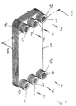
- the three circuit plate heat exchanger shown in Fig. 1 has a front cover plate 1 provided with six port inlet and outlet openings 2 -7 for three flows of fluid media which should pass the exchanger and exchange heat.
- a first flow of fluid - e.g. cooling water - has been designated by the letter x and enters the exchanger through the inlet port 2 and exits the exchanger via the outlet port 3.
- One of the two flows of fluid to be cooled has been designated by the letter y and enters through the inlet port 4 and exits via the outlet port 5.
- the other of the two flows of fluid to be cooled has been designated by the letter z and enters into the exchanger via the inlet port 6 and exits via the outlet port 7.
- the front cover plate 1 carries six tubular fittings 8-13 for connecting the heat exchanger to other parts of the system (not shown) in which the heat exchanging fluids are circulating. Thus the two flows y and z will pass through the heat exchanger counter-currently relative to the flow x.
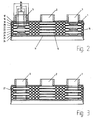
- Fig. 2 is a section along the line II-II of Fig. 1 showing the principle of forming channels used in three circuit heat exchangers and the principle of brazing together channel forming plates according to the prior art as illustrated in WO 95/35474.
- the fluid x enters the exchanger through the port opening 2 in the direction towards a rear cover plate 14 through holes 15 in all plates of the exchanger except for the rear cover plate 14.
- the exchanger comprises ten plates provided with a pressed herring bone type pattern and a peripheral, downwardly extending collar 16. These ten plates have been designated by 17 - 26 and are of two types. The first type is used for the plates having odd numbers and the second type is used for the remaining plates.
- the pattern provided plates 17 - 26 are limiting channels for the three flows of fluid and are generally arranged in pairs of two. One pair is formed by the plates 18 and 19.
- the pair of plates 20, 21 next to the said pair 18, 19 is basically similar thereto, but has been turned 180° in their plan relative to neighboring pairs.
- the outer shape of all plates and the arrangement of the six inlet and outlet ports are identical.
- the ring shaped plate areas around the holes in the plates 20 and 21 at the port 5 engaging each other to prevent the fluid x from entering into the channel between them will have to be brazed together at diameters greater than D 1 , but smaller than D 2 .
- the plates 19 and 20 should be brazed together at a ring shaped area having diameters between D 3 and D 4 .
- Figs. 4 and 5 show a section along the line II-II in Fig. 1 through a heat exchanger according to the present invention.
- Ten plates defining channels are designated by 31 - 40.
- the ring shaped areas of the plates 31-36 sealingly contacting each other and located adjacent to the port holes 5 and 7 are of substantially equal outer and inner diameters.
- Fig. 6 shows the four plates 32, 33, 34 and 35 of Fig. 4 in perspective view, but spaced apart from each other.
- the peripherally extending collar 16 existing at all plates has been downwardly depressed relative the parts 50 surrounding the central port holes 2 and 3.
- a herring bone pattern has been upwardly pressed through the distance h in Fig. 5.
- the following plate 33 in the stack also is provided with a herring bone pattern.
- the plate areas of the plate 34 around the port holes 4 and 5 are not displaced, but so are the plate areas 20 around the port holes 6 and 7 in the same direction as the herring bone pattern - i.e. upwardly, but through the distance H .
- the plate areas around the port holes 4 and 5 of the plates 33, 34 will contact each other, and the displaced areas 20 of the plate 34 around the port holes 7 and 8 will contact the non-displaced plate areas around the corresponding holes in the plate 33.
- the plate 35 in the stack will have a herring bone pattern displaced downwardly through the distance h relative to the plate areas 50 around the port holes 2, 3, 4 and 5.
- the plate areas 20 around the port holes 6 and 7 are displaced downwardly through the distance H.
- the channels defined by the plates have been marked with the letters x, y and z according to their contents of fluids.
- the plate 36 in the stack - not shown in Fig. 6 - will have the same shape as that of the plate 32 and will start a new series of plates.
- the size of the port holes in the plates located at the ports 4 - 7 may vary slightly. This is due to the traditional way of manufacturing the heat exchanger plates.
- the plates are initially stamped to the desired size with uniform diameters of the holes. Subsequently the plates are exposed to one or more pressing operations. The more the plates are deformed during the pressing operations the more the holes will be enlarged. Therefore, the holes near the areas having been displaced through the distance H will be greater than the holes near areas not displaced or only displaced through the distance h . Said small variations are in fact advantageous as they will facilitate the brazing connections.
- the ring shaped contact areas 20 are shown as substantially limited by circular borders having the diameters D1 and D2.
- the holes in the channel forming plates (31-37) need not be circular. They could as well be of other shape - e. g. elliptic or polygonal shape. Only their size, shape and position should be substantially identical.
Landscapes
- Engineering & Computer Science (AREA)
- Physics & Mathematics (AREA)
- Thermal Sciences (AREA)
- Mechanical Engineering (AREA)
- General Engineering & Computer Science (AREA)
- Heat-Exchange Devices With Radiators And Conduit Assemblies (AREA)
- Separation By Low-Temperature Treatments (AREA)
- Waste-Gas Treatment And Other Accessory Devices For Furnaces (AREA)
- Cooling Or The Like Of Semiconductors Or Solid State Devices (AREA)
- Fuel Cell (AREA)
Abstract
Description
at least ten stacked plates provided with a pressed pattern defining channels for three different flows of heat exchanging fluids; where
at least six of the said stacked plates defining channels are each provided with six holes;
all said channel defining plates are of equal outer dimensions, the said holes having identical locations in all plates;
the said channel defining plates having six holes are interconnected by means comprising brazing, soldering, welding or gluing at ring shaped contact areas adjacent to the holes, as well as at their outer periphery.
Claims (4)
- A three circuit plate heat exchanger comprising
at least ten stacked plates (31-40) provided with a pressed pattern defining channels for three different flows (x, y, z) of heat exchanging fluids; where
at least six (31-36) of the said stacked plates (31-40) defining channels are each provided with six holes;
all said channel defining plates (31-40) are of equal outer dimensions, the said holes having identical locations in all plates (31-36);
the said channel defining plates (31-36) having six holes are interconnected by means comprising brazing, soldering, welding or gluing at ring shaped contact areas (20) adjacent to the holes, as well as at their outer periphery.
characterized in that said ring shaped areas (20) of the plates (31-36) adjacent to four of the said six holes are of substantially equal outer and inner shapes, the areas (20) adapted to contact a neighboring plate at two of the holes in the plates being displaced away from a plane containing the contact areas around the remaining four holes in the plates through a distance (H) which is about twice the distance (h) through which the remaining, to the greatest extent displaced channel defining material in the plates has been displaced. - A three circuit plate heat exchanger according to claim 1,
characterized in that said ring shaped areas (20) of the plates (31 -36) adjacent to four of the said holes are limited by substantially circular inner and outer borders. - A three circuit plate heat exchanger according to claim 1 or 2,
characterized in that said channel defining plates (31 - 36) are interconnected by vacuum brazing. - A three circuit plate heat exchanger according to claim 1 or 2,
characterized in that said channel defining plates (31 - 36) are interconnected by brazing in a controlled atmosphere.
Applications Claiming Priority (3)
| Application Number | Priority Date | Filing Date | Title |
|---|---|---|---|
| SE9800783A SE9800783L (en) | 1998-03-11 | 1998-03-11 | Three-circuit plate heat exchanger with specially designed door areas |
| SE9800783 | 1998-03-11 | ||
| PCT/SE1999/000359 WO1999046550A1 (en) | 1998-03-11 | 1999-03-10 | Three circuit plate heat exchanger |
Publications (2)
| Publication Number | Publication Date |
|---|---|
| EP1062472A1 EP1062472A1 (en) | 2000-12-27 |
| EP1062472B1 true EP1062472B1 (en) | 2002-05-22 |
Family
ID=20410491
Family Applications (1)
| Application Number | Title | Priority Date | Filing Date |
|---|---|---|---|
| EP99913789A Expired - Lifetime EP1062472B1 (en) | 1998-03-11 | 1999-03-10 | Three circuit plate heat exchanger |
Country Status (14)
| Country | Link |
|---|---|
| US (1) | US6305466B1 (en) |
| EP (1) | EP1062472B1 (en) |
| JP (1) | JP4267823B2 (en) |
| KR (1) | KR100635659B1 (en) |
| CN (1) | CN1130541C (en) |
| AT (1) | ATE217957T1 (en) |
| AU (1) | AU739681B2 (en) |
| DE (1) | DE69901548T2 (en) |
| DK (1) | DK1062472T3 (en) |
| ES (1) | ES2175959T3 (en) |
| MY (1) | MY133283A (en) |
| PT (1) | PT1062472E (en) |
| SE (1) | SE9800783L (en) |
| WO (1) | WO1999046550A1 (en) |
Cited By (1)
| Publication number | Priority date | Publication date | Assignee | Title |
|---|---|---|---|---|
| DE102007027316B3 (en) * | 2007-06-14 | 2009-01-29 | Bohmann, Dirk, Dr.-Ing. | Plate heat exchanger, comprises two identical heat exchanger plates, where two spiral and looping channel halves, in medium of heat exchanger, proceeds in heat exchanger plate |
Families Citing this family (65)
| Publication number | Priority date | Publication date | Assignee | Title |
|---|---|---|---|---|
| GB0012033D0 (en) * | 2000-05-19 | 2000-07-05 | Llanelli Radiators Ltd | Condenser arrangement and heat exchanger system |
| CA2312113C (en) * | 2000-06-23 | 2005-09-13 | Long Manufacturing Ltd. | Heat exchanger with parallel flowing fluids |
| JP3448265B2 (en) * | 2000-07-27 | 2003-09-22 | 昭 藤山 | Manufacturing method of titanium plate heat exchanger |
| CA2372399C (en) * | 2002-02-19 | 2010-10-26 | Long Manufacturing Ltd. | Low profile finned heat exchanger |
| CA2389119A1 (en) * | 2002-06-04 | 2003-12-04 | Christopher R. Shore | Lateral plate finned heat exchanger |
| CA2423193A1 (en) * | 2003-03-24 | 2004-09-24 | Dana Canada Corporation | Lateral plate surface cooled heat exchanger |
| DE10317263B4 (en) * | 2003-04-14 | 2019-05-29 | Gea Wtt Gmbh | Plate heat exchanger with double-walled heat exchanger plates |
| US7032654B2 (en) | 2003-08-19 | 2006-04-25 | Flatplate, Inc. | Plate heat exchanger with enhanced surface features |
| DE10352880A1 (en) * | 2003-11-10 | 2005-06-09 | Behr Gmbh & Co. Kg | Heat exchanger, in particular charge air / coolant radiator |
| DE10352881A1 (en) | 2003-11-10 | 2005-06-09 | Behr Gmbh & Co. Kg | Heat exchanger, in particular charge air / coolant radiator |
| SE0303307L (en) * | 2003-12-10 | 2004-10-19 | Swep Int Ab | Plate heat exchanger |
| SE527716C2 (en) * | 2004-04-08 | 2006-05-23 | Swep Int Ab | plate heat exchangers |
| DE102004020602A1 (en) * | 2004-04-27 | 2005-12-01 | Mahle Filtersysteme Gmbh | Plate heat exchanger for internal combustion engine, has plate gaps with another two plate gaps, which guide one of three heat exchange fluids, where fluids are exchanged with each other in adjoining gaps in respective same row sequence |
| JP4346562B2 (en) | 2005-01-28 | 2009-10-21 | 東レエンジニアリング株式会社 | Liquid transfer pump |
| CN100582627C (en) * | 2005-05-24 | 2010-01-20 | 达纳加拿大公司 | Multi-fluid heat exchanger |
| CN100401002C (en) * | 2005-07-04 | 2008-07-09 | 缪志先 | Brazing-sheet type heat exchanger capable of using three kinds of medium to exchange heat |
| CN100390489C (en) * | 2005-07-04 | 2008-05-28 | 缪志先 | Plate-type heat exchanger with special turnup structure |
| US7311139B2 (en) * | 2005-08-11 | 2007-12-25 | Generac Power Systems, Inc. | Heat exchanger |
| CN100365372C (en) * | 2005-11-16 | 2008-01-30 | 杭州钦宝制冷设备有限公司 | Three-way guidance tape typed heat exchanger |
| JP2007205634A (en) * | 2006-02-01 | 2007-08-16 | Hisaka Works Ltd | Plate heat exchanger |
| US7703505B2 (en) * | 2006-11-24 | 2010-04-27 | Dana Canada Corporation | Multifluid two-dimensional heat exchanger |
| US8191615B2 (en) * | 2006-11-24 | 2012-06-05 | Dana Canada Corporation | Linked heat exchangers having three fluids |
| US7637112B2 (en) * | 2006-12-14 | 2009-12-29 | Uop Llc | Heat exchanger design for natural gas liquefaction |
| ITPD20070279A1 (en) * | 2007-08-20 | 2009-02-21 | Mta Spa | MULTI-FLUID HEAT EXCHANGER |
| KR101693175B1 (en) * | 2008-01-28 | 2017-01-06 | 프라이무트 요아힘 마롤트 | Multi-passage thermal sheeting and heat exchanger equipped therewith |
| JP2011512509A (en) * | 2008-02-19 | 2011-04-21 | キャリア コーポレイション | Refrigerant vapor compression system |
| US8596339B2 (en) * | 2008-04-17 | 2013-12-03 | Dana Canada Corporation | U-flow stacked plate heat exchanger |
| US8225852B2 (en) * | 2008-04-30 | 2012-07-24 | Dana Canada Corporation | Heat exchanger using air and liquid as coolants |
| SE532524C2 (en) * | 2008-06-13 | 2010-02-16 | Alfa Laval Corp Ab | Heat exchanger plate and heat exchanger assembly include four plates |
| SE533067C2 (en) | 2008-10-03 | 2010-06-22 | Alfa Laval Corp Ab | plate heat exchangers |
| USD679788S1 (en) * | 2008-10-07 | 2013-04-09 | Swep International Ab | Heat exchanger |
| SE0802203L (en) * | 2008-10-16 | 2010-03-02 | Alfa Laval Corp Ab | Hard brazed heat exchanger and method of manufacturing brazed heat exchanger |
| JP5563592B2 (en) * | 2008-12-17 | 2014-07-30 | スウェップ インターナショナル アクティエボラーグ | Brazed heat exchanger port opening |
| CN101476832B (en) * | 2009-01-22 | 2010-10-06 | 林开兵 | Multiple throttling structure of three-fluid plate heat exchanger |
| KR101155811B1 (en) * | 2010-04-05 | 2012-06-12 | 엘지전자 주식회사 | Plate heat exchanger and air conditioner including the same |
| SE534765C2 (en) * | 2010-04-21 | 2011-12-13 | Alfa Laval Corp Ab | Plate heat exchanger plate and plate heat exchanger |
| DE102010024298A1 (en) * | 2010-06-18 | 2011-12-22 | Benteler Automobiltechnik Gmbh | Motor vehicle heat exchanger has heat exchanger cassette and heat exchanger housing, where heat exchanger cassette has multiple heat exchanger plates that are stacked on each other |
| DE102011001311A1 (en) * | 2011-03-16 | 2012-09-20 | Dr. Ing. H.C. F. Porsche Aktiengesellschaft | Device for cooling air stream for passenger compartment of e.g. sport car, has single heat exchanger that cools air stream and/or cooling medium for cooling component, where heat exchanger supplies and discharges coolant and cooling medium |
| EP2694899B1 (en) | 2011-04-01 | 2017-08-02 | Ingersoll-Rand Company | Heat exchanger for a refrigerated air dryer |
| KR101776718B1 (en) * | 2011-11-22 | 2017-09-11 | 현대자동차 주식회사 | Heat exchanger for vehicle |
| KR101284337B1 (en) * | 2011-11-25 | 2013-07-08 | 현대자동차주식회사 | Heat exchanger for vehicle |
| KR101283891B1 (en) * | 2011-11-25 | 2013-07-08 | 현대자동차주식회사 | Heat exchanger for vehicle |
| KR101765582B1 (en) * | 2011-12-06 | 2017-08-08 | 현대자동차 주식회사 | Heat exchanger for vehicle |
| CN102721303B (en) * | 2012-06-08 | 2014-04-02 | 江苏宝得换热设备有限公司 | Three-path plate type heat exchanger |
| KR101886075B1 (en) * | 2012-10-26 | 2018-08-07 | 현대자동차 주식회사 | Heat exchanger for vehicle |
| KR101405186B1 (en) | 2012-10-26 | 2014-06-10 | 현대자동차 주식회사 | Heat exchanger for vehicle |
| KR101376531B1 (en) * | 2012-11-22 | 2014-03-19 | 주식회사 코헥스 | Liquefied natural gas evaporating system for natural gas fueled ship |
| JP6154122B2 (en) * | 2012-12-12 | 2017-06-28 | 株式会社マーレ フィルターシステムズ | Multi-plate stacked heat exchanger |
| US20140352934A1 (en) * | 2013-05-28 | 2014-12-04 | Hamilton Sundstrand Corporation | Plate heat exchanger |
| BR102013017095A2 (en) * | 2013-07-02 | 2015-06-30 | Mahle Metal Leve Sa | Heat exchanger for fuel supply in an internal combustion engine |
| US8881711B1 (en) | 2013-09-03 | 2014-11-11 | Frank Raymond Jasper | Fuel system and components |
| KR101575315B1 (en) * | 2013-10-14 | 2015-12-07 | 현대자동차 주식회사 | Heat exchanger for vehicle |
| US20160377034A1 (en) * | 2015-06-26 | 2016-12-29 | Hyundai Motor Company | Complex heat exchanger |
| JP6278009B2 (en) * | 2015-07-28 | 2018-02-14 | トヨタ自動車株式会社 | Vehicle heat exchanger |
| JP2017110887A (en) * | 2015-12-18 | 2017-06-22 | 株式会社ノーリツ | Plate type heat exchanger, water heating device, and plate type heat exchanger manufacturing method |
| CN110822955A (en) | 2016-02-03 | 2020-02-21 | 摩丁制造公司 | Battery Cooling Plate Heat Exchangers and Plate Assemblies |
| DE102016201712A1 (en) * | 2016-02-04 | 2017-08-10 | Mahle International Gmbh | Stacked plate heat exchanger, in particular for a motor vehicle |
| CN107621182B (en) * | 2016-07-14 | 2020-08-07 | 杭州三花研究院有限公司 | Heat exchange assembly |
| SE541355C2 (en) * | 2016-12-22 | 2019-08-13 | Alfa Laval Corp Ab | A plate heat exchanger with six ports for three different media |
| WO2019041046A1 (en) * | 2017-08-31 | 2019-03-07 | Dana Canada Corporation | Multi-fluid heat exchanger |
| WO2020112304A1 (en) * | 2018-11-27 | 2020-06-04 | Modine Manufacturing Company | Heat exchanger for cooling multiple fluids |
| IT201900000665U1 (en) * | 2019-02-27 | 2020-08-27 | Onda S P A | PLATE HEAT EXCHANGER. |
| FR3107342B1 (en) * | 2019-12-13 | 2022-09-02 | Valeo Systemes Thermiques | Three-fluid plate heat exchanger |
| EP4148366B1 (en) * | 2021-09-08 | 2024-07-10 | Valeo Autosystemy Sp. z o.o. | A heat exchanger |
| CN115950292B (en) * | 2022-11-30 | 2025-07-22 | 孚尔法(江苏)换热设备制造有限公司 | Double-walled heat exchanger plate and manufacturing method thereof |
Family Cites Families (7)
| Publication number | Priority date | Publication date | Assignee | Title |
|---|---|---|---|---|
| FR958699A (en) * | 1942-05-22 | 1950-03-17 | ||
| JPH06100434B2 (en) * | 1985-04-12 | 1994-12-12 | 株式会社日阪製作所 | Plate type heat exchanger |
| US5180004A (en) * | 1992-06-19 | 1993-01-19 | General Motors Corporation | Integral heater-evaporator core |
| DE4409833A1 (en) * | 1994-03-22 | 1995-10-05 | Biedermann Motech Gmbh | Stabilizing device, in particular for stabilizing the spine |
| US5462113A (en) * | 1994-06-20 | 1995-10-31 | Flatplate, Inc. | Three-circuit stacked plate heat exchanger |
| SE504799C2 (en) * | 1995-08-23 | 1997-04-28 | Swep International Ab | Triple circuit heat exchanger |
| SE9700614D0 (en) * | 1997-02-21 | 1997-02-21 | Alfa Laval Ab | Flat heat exchanger for three heat exchanging fluids |
-
1998
- 1998-03-11 SE SE9800783A patent/SE9800783L/en not_active IP Right Cessation
-
1999
- 1999-03-10 PT PT99913789T patent/PT1062472E/en unknown
- 1999-03-10 US US09/623,792 patent/US6305466B1/en not_active Expired - Lifetime
- 1999-03-10 AT AT99913789T patent/ATE217957T1/en active
- 1999-03-10 AU AU31781/99A patent/AU739681B2/en not_active Ceased
- 1999-03-10 KR KR1020007010110A patent/KR100635659B1/en not_active Expired - Fee Related
- 1999-03-10 EP EP99913789A patent/EP1062472B1/en not_active Expired - Lifetime
- 1999-03-10 ES ES99913789T patent/ES2175959T3/en not_active Expired - Lifetime
- 1999-03-10 JP JP2000535887A patent/JP4267823B2/en not_active Expired - Fee Related
- 1999-03-10 DE DE69901548T patent/DE69901548T2/en not_active Expired - Lifetime
- 1999-03-10 CN CN99805005A patent/CN1130541C/en not_active Expired - Fee Related
- 1999-03-10 DK DK99913789T patent/DK1062472T3/en active
- 1999-03-10 WO PCT/SE1999/000359 patent/WO1999046550A1/en not_active Ceased
- 1999-03-10 MY MYPI99000881A patent/MY133283A/en unknown
Cited By (1)
| Publication number | Priority date | Publication date | Assignee | Title |
|---|---|---|---|---|
| DE102007027316B3 (en) * | 2007-06-14 | 2009-01-29 | Bohmann, Dirk, Dr.-Ing. | Plate heat exchanger, comprises two identical heat exchanger plates, where two spiral and looping channel halves, in medium of heat exchanger, proceeds in heat exchanger plate |
Also Published As
| Publication number | Publication date |
|---|---|
| CN1130541C (en) | 2003-12-10 |
| AU739681B2 (en) | 2001-10-18 |
| SE509579C2 (en) | 1999-02-08 |
| EP1062472A1 (en) | 2000-12-27 |
| DE69901548T2 (en) | 2002-12-05 |
| SE9800783L (en) | 1999-02-08 |
| MY133283A (en) | 2007-10-31 |
| US6305466B1 (en) | 2001-10-23 |
| KR100635659B1 (en) | 2006-10-17 |
| ES2175959T3 (en) | 2002-11-16 |
| AU3178199A (en) | 1999-09-27 |
| PT1062472E (en) | 2002-09-30 |
| KR20010041825A (en) | 2001-05-25 |
| WO1999046550A1 (en) | 1999-09-16 |
| ATE217957T1 (en) | 2002-06-15 |
| JP2002506196A (en) | 2002-02-26 |
| DE69901548D1 (en) | 2002-06-27 |
| CN1297524A (en) | 2001-05-30 |
| SE9800783D0 (en) | 1998-03-11 |
| JP4267823B2 (en) | 2009-05-27 |
| DK1062472T3 (en) | 2002-07-22 |
Similar Documents
| Publication | Publication Date | Title |
|---|---|---|
| US6305466B1 (en) | Three circuit plate heat exchanger | |
| US6142221A (en) | Three-circuit plate heat exchanger | |
| EP0418227B1 (en) | Permanently joined plate heat exchanger | |
| EP0527875B1 (en) | Brazed plate heat exchanger | |
| EP0702777B1 (en) | Plate heat exchanger | |
| EP1405022B1 (en) | Heat transfer plate, plate pack and plate heat exchanger | |
| EP1738126B1 (en) | A plate heat exchanger | |
| EP1702193B1 (en) | A plate heat exchanger | |
| EP0503080B1 (en) | Laminated heat exchanger | |
| SE545724C2 (en) | A double wall plate heat exchanger | |
| US7204297B2 (en) | Plate-type heat exchanger with double-walled heat transfer plates | |
| US7870671B2 (en) | Method of manufacturing a plate heat exchanger | |
| US4589480A (en) | Plate heat exchanger | |
| EP0724127B1 (en) | Flat-plate heat and mass transfer exchanger | |
| EP4001818B1 (en) | Plate-and-shell heat exchanger and a heat transfer plate for a plate-and-shell heat exchanger | |
| JP2000180077A (en) | Plate type heat exchanger | |
| JP7724219B2 (en) | Heat exchanger with recesses to avoid stagnant medium | |
| HK1072803B (en) | Plate heat exchanger with double-walled heat exchanger plates |
Legal Events
| Date | Code | Title | Description |
|---|---|---|---|
| PUAI | Public reference made under article 153(3) epc to a published international application that has entered the european phase |
Free format text: ORIGINAL CODE: 0009012 |
|
| 17P | Request for examination filed |
Effective date: 20000913 |
|
| AK | Designated contracting states |
Kind code of ref document: A1 Designated state(s): AT BE CH CY DE DK ES FI FR GB GR IE IT LI LU MC NL PT SE |
|
| GRAG | Despatch of communication of intention to grant |
Free format text: ORIGINAL CODE: EPIDOS AGRA |
|
| GRAG | Despatch of communication of intention to grant |
Free format text: ORIGINAL CODE: EPIDOS AGRA |
|
| GRAH | Despatch of communication of intention to grant a patent |
Free format text: ORIGINAL CODE: EPIDOS IGRA |
|
| 17Q | First examination report despatched |
Effective date: 20010913 |
|
| GRAH | Despatch of communication of intention to grant a patent |
Free format text: ORIGINAL CODE: EPIDOS IGRA |
|
| GRAA | (expected) grant |
Free format text: ORIGINAL CODE: 0009210 |
|
| REF | Corresponds to: |
Ref document number: 217957 Country of ref document: AT Date of ref document: 20020615 Kind code of ref document: T |
|
| REG | Reference to a national code |
Ref country code: GB Ref legal event code: FG4D |
|
| REG | Reference to a national code |
Ref country code: CH Ref legal event code: EP |
|
| REG | Reference to a national code |
Ref country code: IE Ref legal event code: FG4D |
|
| REF | Corresponds to: |
Ref document number: 69901548 Country of ref document: DE Date of ref document: 20020627 |
|
| REG | Reference to a national code |
Ref country code: CH Ref legal event code: NV Representative=s name: ISLER & PEDRAZZINI AG |
|
| REG | Reference to a national code |
Ref country code: DK Ref legal event code: T3 |
|
| PG25 | Lapsed in a contracting state [announced via postgrant information from national office to epo] |
Ref country code: SE Free format text: LAPSE BECAUSE OF FAILURE TO SUBMIT A TRANSLATION OF THE DESCRIPTION OR TO PAY THE FEE WITHIN THE PRESCRIBED TIME-LIMIT Effective date: 20020822 |
|
| REG | Reference to a national code |
Ref country code: PT Ref legal event code: SC4A Free format text: AVAILABILITY OF NATIONAL TRANSLATION Effective date: 20020716 |
|
| ET | Fr: translation filed | ||
| REG | Reference to a national code |
Ref country code: GR Ref legal event code: EP Ref document number: 20020402805 Country of ref document: GR |
|
| REG | Reference to a national code |
Ref country code: ES Ref legal event code: FG2A Ref document number: 2175959 Country of ref document: ES Kind code of ref document: T3 |
|
| PG25 | Lapsed in a contracting state [announced via postgrant information from national office to epo] |
Ref country code: LU Free format text: LAPSE BECAUSE OF NON-PAYMENT OF DUE FEES Effective date: 20030310 Ref country code: CY Free format text: LAPSE BECAUSE OF FAILURE TO SUBMIT A TRANSLATION OF THE DESCRIPTION OR TO PAY THE FEE WITHIN THE PRESCRIBED TIME-LIMIT Effective date: 20030310 |
|
| PLBE | No opposition filed within time limit |
Free format text: ORIGINAL CODE: 0009261 |
|
| STAA | Information on the status of an ep patent application or granted ep patent |
Free format text: STATUS: NO OPPOSITION FILED WITHIN TIME LIMIT |
|
| PG25 | Lapsed in a contracting state [announced via postgrant information from national office to epo] |
Ref country code: MC Free format text: LAPSE BECAUSE OF NON-PAYMENT OF DUE FEES Effective date: 20030331 |
|
| 26N | No opposition filed |
Effective date: 20030225 |
|
| REG | Reference to a national code |
Ref country code: CH Ref legal event code: PCAR Free format text: ISLER & PEDRAZZINI AG;POSTFACH 1772;8027 ZUERICH (CH) |
|
| PGFP | Annual fee paid to national office [announced via postgrant information from national office to epo] |
Ref country code: IE Payment date: 20120313 Year of fee payment: 14 |
|
| PGFP | Annual fee paid to national office [announced via postgrant information from national office to epo] |
Ref country code: PT Payment date: 20120217 Year of fee payment: 14 |
|
| PGFP | Annual fee paid to national office [announced via postgrant information from national office to epo] |
Ref country code: FI Payment date: 20120312 Year of fee payment: 14 Ref country code: GR Payment date: 20120326 Year of fee payment: 14 |
|
| REG | Reference to a national code |
Ref country code: PT Ref legal event code: MM4A Free format text: LAPSE DUE TO NON-PAYMENT OF FEES Effective date: 20130910 |
|
| PG25 | Lapsed in a contracting state [announced via postgrant information from national office to epo] |
Ref country code: PT Free format text: LAPSE BECAUSE OF NON-PAYMENT OF DUE FEES Effective date: 20130910 Ref country code: FI Free format text: LAPSE BECAUSE OF NON-PAYMENT OF DUE FEES Effective date: 20130310 |
|
| REG | Reference to a national code |
Ref country code: GR Ref legal event code: ML Ref document number: 20020402805 Country of ref document: GR Effective date: 20131002 |
|
| REG | Reference to a national code |
Ref country code: IE Ref legal event code: MM4A |
|
| PG25 | Lapsed in a contracting state [announced via postgrant information from national office to epo] |
Ref country code: IE Free format text: LAPSE BECAUSE OF NON-PAYMENT OF DUE FEES Effective date: 20130310 |
|
| PG25 | Lapsed in a contracting state [announced via postgrant information from national office to epo] |
Ref country code: GR Free format text: LAPSE BECAUSE OF NON-PAYMENT OF DUE FEES Effective date: 20131002 |
|
| PGFP | Annual fee paid to national office [announced via postgrant information from national office to epo] |
Ref country code: DK Payment date: 20150312 Year of fee payment: 17 |
|
| PGFP | Annual fee paid to national office [announced via postgrant information from national office to epo] |
Ref country code: AT Payment date: 20150312 Year of fee payment: 17 |
|
| REG | Reference to a national code |
Ref country code: FR Ref legal event code: PLFP Year of fee payment: 18 |
|
| REG | Reference to a national code |
Ref country code: DK Ref legal event code: EBP Effective date: 20160331 |
|
| REG | Reference to a national code |
Ref country code: AT Ref legal event code: MM01 Ref document number: 217957 Country of ref document: AT Kind code of ref document: T Effective date: 20160310 |
|
| PG25 | Lapsed in a contracting state [announced via postgrant information from national office to epo] |
Ref country code: AT Free format text: LAPSE BECAUSE OF NON-PAYMENT OF DUE FEES Effective date: 20160310 |
|
| REG | Reference to a national code |
Ref country code: FR Ref legal event code: PLFP Year of fee payment: 19 |
|
| PGFP | Annual fee paid to national office [announced via postgrant information from national office to epo] |
Ref country code: NL Payment date: 20170307 Year of fee payment: 19 Ref country code: DE Payment date: 20170308 Year of fee payment: 19 Ref country code: FR Payment date: 20170306 Year of fee payment: 19 Ref country code: CH Payment date: 20170309 Year of fee payment: 19 |
|
| PG25 | Lapsed in a contracting state [announced via postgrant information from national office to epo] |
Ref country code: DK Free format text: LAPSE BECAUSE OF NON-PAYMENT OF DUE FEES Effective date: 20160331 |
|
| PGFP | Annual fee paid to national office [announced via postgrant information from national office to epo] |
Ref country code: BE Payment date: 20170307 Year of fee payment: 19 Ref country code: GB Payment date: 20170306 Year of fee payment: 19 |
|
| PGFP | Annual fee paid to national office [announced via postgrant information from national office to epo] |
Ref country code: ES Payment date: 20170308 Year of fee payment: 19 Ref country code: IT Payment date: 20170308 Year of fee payment: 19 |
|
| REG | Reference to a national code |
Ref country code: DE Ref legal event code: R119 Ref document number: 69901548 Country of ref document: DE |
|
| REG | Reference to a national code |
Ref country code: CH Ref legal event code: PL |
|
| REG | Reference to a national code |
Ref country code: NL Ref legal event code: MM Effective date: 20180401 |
|
| GBPC | Gb: european patent ceased through non-payment of renewal fee |
Effective date: 20180310 |
|
| REG | Reference to a national code |
Ref country code: BE Ref legal event code: MM Effective date: 20180331 |
|
| PG25 | Lapsed in a contracting state [announced via postgrant information from national office to epo] |
Ref country code: NL Free format text: LAPSE BECAUSE OF NON-PAYMENT OF DUE FEES Effective date: 20180401 |
|
| PG25 | Lapsed in a contracting state [announced via postgrant information from national office to epo] |
Ref country code: DE Free format text: LAPSE BECAUSE OF NON-PAYMENT OF DUE FEES Effective date: 20181002 |
|
| PG25 | Lapsed in a contracting state [announced via postgrant information from national office to epo] |
Ref country code: IT Free format text: LAPSE BECAUSE OF NON-PAYMENT OF DUE FEES Effective date: 20180310 Ref country code: BE Free format text: LAPSE BECAUSE OF NON-PAYMENT OF DUE FEES Effective date: 20180331 Ref country code: CH Free format text: LAPSE BECAUSE OF NON-PAYMENT OF DUE FEES Effective date: 20180331 Ref country code: GB Free format text: LAPSE BECAUSE OF NON-PAYMENT OF DUE FEES Effective date: 20180310 Ref country code: LI Free format text: LAPSE BECAUSE OF NON-PAYMENT OF DUE FEES Effective date: 20180331 |
|
| PG25 | Lapsed in a contracting state [announced via postgrant information from national office to epo] |
Ref country code: FR Free format text: LAPSE BECAUSE OF NON-PAYMENT OF DUE FEES Effective date: 20180331 |
|
| REG | Reference to a national code |
Ref country code: ES Ref legal event code: FD2A Effective date: 20190904 |
|
| PG25 | Lapsed in a contracting state [announced via postgrant information from national office to epo] |
Ref country code: ES Free format text: LAPSE BECAUSE OF NON-PAYMENT OF DUE FEES Effective date: 20180311 |