EP1061824B1 - Protective helmet system - Google Patents
Protective helmet system Download PDFInfo
- Publication number
- EP1061824B1 EP1061824B1 EP98938039A EP98938039A EP1061824B1 EP 1061824 B1 EP1061824 B1 EP 1061824B1 EP 98938039 A EP98938039 A EP 98938039A EP 98938039 A EP98938039 A EP 98938039A EP 1061824 B1 EP1061824 B1 EP 1061824B1
- Authority
- EP
- European Patent Office
- Prior art keywords
- helmet
- face shield
- cam
- protective
- seal
- Prior art date
- Legal status (The legal status is an assumption and is not a legal conclusion. Google has not performed a legal analysis and makes no representation as to the accuracy of the status listed.)
- Expired - Lifetime
Links
Images


Classifications
-
- A—HUMAN NECESSITIES
- A42—HEADWEAR
- A42B—HATS; HEAD COVERINGS
- A42B3/00—Helmets; Helmet covers ; Other protective head coverings
- A42B3/04—Parts, details or accessories of helmets
- A42B3/18—Face protection devices
- A42B3/22—Visors
-
- A—HUMAN NECESSITIES
- A42—HEADWEAR
- A42B—HATS; HEAD COVERINGS
- A42B3/00—Helmets; Helmet covers ; Other protective head coverings
- A42B3/04—Parts, details or accessories of helmets
- A42B3/18—Face protection devices
- A42B3/22—Visors
- A42B3/225—Visors with full face protection, e.g. for industrial safety applications
-
- A—HUMAN NECESSITIES
- A42—HEADWEAR
- A42B—HATS; HEAD COVERINGS
- A42B3/00—Helmets; Helmet covers ; Other protective head coverings
- A42B3/04—Parts, details or accessories of helmets
- A42B3/10—Linings
-
- A—HUMAN NECESSITIES
- A42—HEADWEAR
- A42B—HATS; HEAD COVERINGS
- A42B3/00—Helmets; Helmet covers ; Other protective head coverings
- A42B3/32—Collapsible helmets; Helmets made of separable parts ; Helmets with movable parts, e.g. adjustable
- A42B3/326—Helmets with movable or separable chin or jaw guard
-
- A—HUMAN NECESSITIES
- A61—MEDICAL OR VETERINARY SCIENCE; HYGIENE
- A61F—FILTERS IMPLANTABLE INTO BLOOD VESSELS; PROSTHESES; DEVICES PROVIDING PATENCY TO, OR PREVENTING COLLAPSING OF, TUBULAR STRUCTURES OF THE BODY, e.g. STENTS; ORTHOPAEDIC, NURSING OR CONTRACEPTIVE DEVICES; FOMENTATION; TREATMENT OR PROTECTION OF EYES OR EARS; BANDAGES, DRESSINGS OR ABSORBENT PADS; FIRST-AID KITS
- A61F9/00—Methods or devices for treatment of the eyes; Devices for putting-in contact lenses; Devices to correct squinting; Apparatus to guide the blind; Protective devices for the eyes, carried on the body or in the hand
- A61F9/04—Eye-masks ; Devices to be worn on the face, not intended for looking through; Eye-pads for sunbathing
- A61F9/06—Masks, shields or hoods for welders
- A61F9/064—Masks, shields or hoods for welders with two windows, one for viewing and one for use during the welding process
Definitions
- the present invention relates to a protective helmet system convertible between multiple protection classifications.
- Protective helmets are commonly worn by people to shield their heads from flying or falling objects.
- the helmet usually has a rigid protective shell of an impact resistant material.
- helmets have face shields attached thereto to protect the wearer's face.
- the helmet and face shield can form a protective enclosure to which is supplied uncontaminated air. Respirators are frequently combined with helmets and face shields to protect workers in areas where the air may be contaminated by toxic or noxious substances, such as particulates, gases and vapors.
- NIOSH National Institute of Occupational Safety and Health
- ANSI American National Standards Institute
- Other agencies and organizations around the world also establish safety standards for helmets and respirators.
- some of the standards relate to impact energy attenuation, penetration resistance, force transmission, stiffness, flammability, electrical insulation, and head coverage.
- loose fitting face piece defines a ANSI classification of a respiratory protective system in which the respirator enclosure is designed to form a partial seal with the face. Loose fitting face pieces do not seal on the neck and shoulders of the wearer and may or may not offer head protection against impacts and penetration. Positive pressure respiratory air supplied to such a system assists in forming a protective shield around the worker's face.
- a "loose fitting helmet” is another ANSI classification in which the respirator completely covers the head and neck, and may cover portions of the shoulders. Loose fitting helmets typically seal around the neck of the user. ANSI standards permit the use of "loose fitting face pieces" for exposures of up to 25 times the permissible exposure limit (PEL) for most contaminants. Loose fitting face pieces are typically not worn by users with facial hair.
- a loose fitting helmet can be used with up to 1,000 times the PEL, and may be used with facial hair.
- Welding operations present a number of potential hazards to the welder that require the welder to use a specially designed protective device. Welding can cause sparks and hot metal debris to fly off the work piece. Welders often wear a clear face shield attached to a helmet to protect their head and face when the welding shield is raised. Welding can also generate toxic or noxious fumes requiring the welder to wear a respiratory system. Welding also causes high intensity light to be generated, requiring the welder to wear a darkened lens over their eyes to prevent eye damage.
- Protective systems with the highest level of protection may not be optimum for a particular job that does not require that level of protection.
- protective systems with a high level of protection can be heavy, may cause some discomfort to the wearer and can be costly.
- a loose fitting face piece system is lighter, less expensive, and more convenient than a loose fitting helmet, such systems are not acceptable for some applications. Therefore, many different types of helmets, respirators and face shields have been developed to meet the many different applications and standards that exist. Consequently, manufacturers have been forced to produce a variety of different systems for different conditions, as well as requiring users to stock and maintain many different systems.
- GB-A-1 266 818 relates to a visor assembly for a helmet comprising a first shaft, a second shaft, means for mounting said shafts on said helmet for rotation about a common axis, a first visor, means mounting said first visor on one of said shafts for rotation therewith, means mounting said first visor on the shaft for rotation relative thereto, a second visor, means mounting said second visor on said other shaft for rotation therewith, and means mounting said second visor on said one shaft for rotation relative thereto.
- the present invention is defined by the features of the claims and is directed to a protective helmet system that can be configured for a variety of protection classifications.
- the ability to use the same helmet and face shields in multiple respiratory protection classifications reduces the number of different systems that need to be manufactured and reduces the number of components that need to be maintained in inventory.
- the present invention is also directed to a compact attaching mechanism that permits multiple face shields to be releasably attached to the helmet, either individually or simultaneously.
- the compact nature of the attaching mechanism provides for tight sealing engagement between the various components of the present protective helmet system.
- All of the embodiments of the present invention can be used with a seal extending between the protective helmet system and the user.
- the seal can form either a loose fitting face piece or a loose fitting helmet.
- a source of pressurized air is optionally provided to the protective helmet system to form a positive pressure respirator.
- a jaw piece is attachable to a base edge of the helmet.
- the jaw piece and a portion of the base edge of the helmet define a user viewing window.
- a first face shield is pivotable between an open position and a closed position extending across the viewing window.
- a seal is provided to engage with a perimeter of the viewing window when the first face shield is in the closed position.
- the attaching assembly for attaching the first face shield comprises a helmet cam having first helmet cam surfaces configured to releasably attach the first face shield to the protective helmet system and second helmet cam surfaces configured to releasably attach a second face shield to the protective helmet.
- the attaching assembly generates a first biasing force to bias the seal toward the perimeter of the viewing window when the first face shield is in the closed position and a second biasing force to bias the first face shield away from the jaw piece when in the open position.
- the protective helmet system comprises a helmet, a first face shield pivotable between an open position and a closed position, and an attaching assembly.
- the attaching assembly comprises a helmet cam having first helmet cam surfaces extending radially outward from the helmet cam configured to releasably attach the first face shield to the protective helmet system and second helmet cam surfaces extending axially from the helmet cam configured to releasably attach an optional second face shield to the protective helmet.
- the attaching assembly generates a first biasing force to bias the first face shield seal downward when the first face shield is in the closed position and a second biasing force to bias the first face shield upward when in the open position.
- the present invention is also directed to a modular protective helmet system kit for multiple protection classification.
- a first face shield is optionally attachable to the helmet.
- the first face shield is pivotable between an open position and a closed position extending across a viewing window when attached to the helmet.
- a second face shield is optionally attachable to the helmet.
- the second face shield is configured to extend over the first face shield and substantially across the viewing window when attached to the helmet.
- the attaching mechanism includes first helmet cam surfaces configured to releasably attach the first face shield to the protective helmet system and second helmet cam surfaces configured to releasably attach the second face shield to the protective helmet.
- the attaching assembly generates a downward biasing force when the first face shield is in the closed position and an upward biasing force when the face shield is in the open position.
- An extender having a neck seal is optionally attachable to a base edge of the first face shield.
- a jaw piece having a sealing surface is optionally attached to a base edge of the helmet.
- a seal is provided to engage with the sealing surface when the first face shield is in the closed position.
- Figure 1 is an exploded perspective view of a protective helmet system in accordance with the present invention.
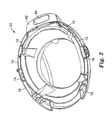
- Figure 2 is a bottom view of a helmet suitable for use in the present protective helmet system.
- Figure 3 is a perspective view of a combination helmet and jaw piece in accordance with the present protective helmet system.
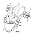
- Figure 4 is a perspective view of an attaching assembly for use in the present protective helmet system.
- Figure 5 is a sectional view of the attaching assembly of Figure 4.
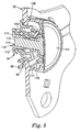
- Figure 6 illustrates engagement of the attaching assembly with a face shield in the closed position.
- Figure 7 illustrates engagement of the attaching assembly with a face shield in the opened position.
- Figure 8 is a perspective view of a modified attaching assembly for use in the present protective helmet system.
- Figure 9 is a perspective view of a second face shield on the protective helmet system in accordance with the present invention.
- Figure 10 is a perspective view of an interface on the second face shield for use with the attaching assembly.
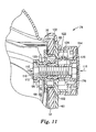
- Figure 11 is a sectional view of the attaching assembly of Figure 8.
- FIG 1 is a perspective view of a protective helmet system 20 including a helmet 22 in accordance with the present invention.
- Helmet 22 can be a simple bump cap (such as defined in European standard CEN EN 812) or a hard hat meeting more stringent protection classifications (such as defined in ANSI Z89. 1-1997).
- Protective lens system 28 illustrates a variety of protective lenses that can be releasably attached to the helmet 22.
- the helmet 22 can be used alone or in combination with a jaw piece 24 to form a protective enclosure 26 around the user's face (not shown).
- the jaw piece 24 is preferably rigidly attached to the helmet 22.
- the jaw pieces 24 provide registration and sealing surfaces 52, 54 for the various components of the protective lens system 28.
- An extender 61 having a face seal 62 can optionally be attached to one of the components of the protective lens system 28 to form the protective enclosure around the user's face (see Figure 4).
- Wide view lens face shield 30 includes a wide view frame 32 having an elastomeric peripheral seal 34 along an inner surface 36.
- a transparent wide view lens 38 is releasably mounted within the wide view frame 32.
- the wide view lens face shield 30 is configured to extend around a perimeter 40A of a viewing window 42 formed between the helmet 22 and the jaw piece 24, or a perimeter 40B of the viewing window 42 formed between the helmet 22 and the extender 61 (see figure 4).
- the elastomeric peripheral seal 34 is configured to engage with a first sealing surface 50 along an upper edge of the helmet 22 and the second and third sealing surfaces 52, 54 located on the jaw piece 24 (see Figure 9). The seal 34 may also form a sealing engagement with the extender 61.
- the wide view frame 32 includes mounting holes 56, 58 for pivotal attachment to the helmet 22 as will be discussed in detail below.
- Welding shield 60 may be pivotally attached to the helmet 22, either alone or in combination with the wide view lens face shield 30.
- the welding shield includes mounting holes 66, 68 for rotational attachment to the helmet 22.
- the protective helmet system 20 may optionally include a shroud 64 configured to extend over the user's shoulders.
- the shroud 64 is typically attached to the jaw piece 24 and a base edge 70 of the helmet 22.
- the extender 61 has a face seal 62 that extends between the protective helmet system 20 and the user.
- the shroud 64 or face seal 62 used in combination with a source of pressurized air permits the present protective helmet system 20 to form a positive pressure respirator.
- FIG 2 is a bottom perspective view of the base edge 70 of the helmet 22 having a plurality of jaw piece mounting slots 72 arranged for engagement with the jaw piece 24 (see Figure 3).
- the base edge 70 also includes a pair of helmet cam clip housings 74, 76 for releasably mounting an attaching assembly 78 to the helmet 22 (see Figure 4).
- Pressure port 80 is provided at a rear edge 82 of the helmet 22 for attachment to a source of pressurized air (not shown) to form an atmosphere supplied device, also known as a positive pressure respirator.
- the source of pressurized air assists in maintaining a net flow of air out from the protective enclosure 26, thereby minimizing the chance that contaminant will penetrate into the protective enclosure 26.
- FIG 3 is a perspective view of the helmet 22 in the process of being engaged to the jaw piece 24.
- the jaw piece 24 includes a series of connector members 84 configured to engage with the jaw piece mounting slot 72 along the base edge 70 of the helmet 22.
- the connector members 84 preferably include compression ribs 86 to ensure a tight fit between the jaw piece 24 and the helmet 22. Attachment of the jaw piece 24 to the helmet 22 converts a loose fitting face piece system into a loose fitting helmet construction.
- the jaw piece 24 is releasably attached to the helmet 22.
- the jaw piece 24 may be permanently adhered to the helmet 22 using a suitable adhesive.
- FIGs 4 and 5 illustrate the engagement of the attaching assembly 78 to wide view frame 32 of the face shield 30 to the helmet 22.
- the helmet 22 includes a helmet cam recess 90 having a hole 92 for receiving an elongated portion 94 on a helmet cam 96.
- the helmet cam 96 is preferably symmetrical so that it can be used on either side of the helmet 22.
- a helmet cam clip 98 is inserted through the helmet cam clip housing 74 (see Figure 2) that compressibly engages with a slot 100 on the helmet cam 96.
- the helmet cam 96, helmet cam clip 98, and weld cam 102 preferably includes compression ribs 99 to form an interference fit with the mating component.
- Pivot post 110 having a flange 112 is inserted through the rear of the helmet cam 96 for engagement with a knob assembly 114.
- the pivot post 110 preferably has an internally threaded portion 115 for engagement with a threaded member 116 on the knob assembly 114.
- Surface 109 on the knob assembly 114 retains the frame 32 to the helmet cam 96.
- the pivot post 110 also includes tabs 111 configured to engage with slots 113 on the helmet cam 96 to prevent rotation of the pivot post 110 during engagement with the knob assembly 114.
- the knob assembly 114 preferably defines a recess 117 having tabs 119 for optionally retaining a spring 172 (see Figure 8), as will be discussed below.
- the exposed side of the helmet cam 96 includes a plurality of radial cam surfaces 102 that are positioned to engage radially with a cam engaging surface 104 of a spring 106 located on the wide view frame 32 adjacent to the holes 56, 58.
- the helmet cam 96 includes a series of axial cam surfaces 120 for engagement with corresponding axial cam surfaces 122 on a second face shield cam 124 (see Figure 11).
- Figure 6 is a plane view of an inside edge of the wide view frame 32 of the face shield 30 engaged with the helmet cam 96 in a closed position 130.
- the spring 106 is mounted in a recess 132 to permit flexure along a spring axis 134.
- the cam engaging surface 104 is not fully engaged with the radial cam surface 102A, so as to create a downward biasing force 136.
- the biasing force 136 creates a slight separation of the spring 106 from the recess structure 132 at the location 140.
- the net effect of the biasing force 136 is to bias the peripheral seal 34 toward the perimeter 40 of the viewing window 42 (see Figure 1).
- Also seen in Figure 6 are raised portions 35 on the peripheral seal 34 configured for engaging with the perimeter 40 of the viewing window 42 when the face shield 30 is in the closed position 130.
- Figure 7 illustrates the wide view lens face shield 30 biased in an open position 150.
- the radial cam surface 102B is slightly offset from the cam engaging surface 104 of the spring 106 so as to create an upward biasing force 152.
- the biasing force 152 creates a slight separation between the spring 106 and the recess structure 132 at the location 154.
- FIGs 8 through 11 illustrate use of the attaching assembly 78 to include a second face shield 60, such as the welding shield illustrated in Figure 9, to the present protective helmet system 20.
- the knob assembly 114 is slightly modified to include a spring 172 to provide a bias between the second face shield cam surfaces 122 and the axial cam surfaces 120 located on the helmet cam 96.
- the second face shield cam 124 is illustrated as a component separate from the second face shield 60.
- Attachment tabs 176 are preferably included for releasable engagement with the second face shield 60 (see Figure 10).
- the cam surfaces 122 can be integrally formed on the second face shield 60.
- the pivot post 110 includes spline teeth 180 positioned to engage with corresponding spline teeth 182 on an inside surface of hole 184 on the second face shield cam 124. Consequently, the pivot post 110 does not rotate when the threaded member 116 of the knob assembly 114 is engaged with the pivot post 110 to generate an axial compressive force 115 Once the cam surfaces 120, 122 are compressively engaged by the axial compressive force 115, the second face shield cam 124, pivot post 110 and knob assembly 114 rotate with the second face shield 60.
- the third sealing surface 54 on the jaw piece 24 comprises a ridge configured to engage with an L-shaped lip 190 on the second face shield 60.
- the combination of ridge 54 and L-shaped lip 180 creates a tortuous path that minimizes the penetration of direct and indirect radiation into the enclosure 26.
- the wide view frame 32 engages with the radial cam surfaces 102 and the second face shield 60 engages with the axial cam surfaces 120 on the helmet cam 96. Consequently, the attaching assembly 78 is extremely compact, permitting the wide view lens face shield 30 and second face shield 60 to be releasably attached with minimal offsets from the helmet 22. That is, the attaching assembly 78 provides a tight sealing engagement between the wide view lens face shield 30, the second face shield 60 and the helmet 22, thereby maximizing sealing capabilities of the system 20.
- the present protective helmet system 20 can be arranged in a variety of configurations.
- a bump cap helmet 22 and the extender 61 (and face seal 62) can be configured with the wide view lens face shield 30, the welding shield 60, or both.
- Pressurized air is supplied to the loose fitting face piece to form a positive pressure respirator suitable for exposures of up to 25 times the permissible exposure limit (PEL) for most contaminants.
- PEL permissible exposure limit
- a hard hat is substituted for the bump cap.
- the shroud 64 and jaw piece 24 are attached to the hard hat helmet 22 to form a loose fitting helmet.
- the loose fitting helmet can be configured with the face shield 30, welding shield 60, or both.
- the present protective helmet system 20 can be used without a source of pressurized air, preferably without the face seal 62 or shroud 64.
Description
Claims (10)
- A protective helmet system, comprising:a helmet (22);a first face shield (30) pivotable between an open position and a closed position; andan attaching assembly (78) comprising a helmet cam (96) having first helmet cam surfaces (102) configured to releasably attach the first face shield (30) to the protective helmet system and second helmet cam surfaces (120) configured to releasably attach an optional second face shield (60) to the protective helmet, characterised in that the attaching assembly (78) generates a first biasing force to bias the first face shield seat downward when the first face shield is in the closed position and a second biasing force to bias the first face shield upward when in the open position.
- The system of claim 1 wherein the first face shield (30) comprises a spring (106) having a cam engaging surface (104) radially engaged with the first helmet cam surfaces.
- The system of claim 1 further comprising a second face shield (60) releasably attached to the helmet.
- The system of claim 3 wherein the second face shield (60) comprises second face shield cam surface (122) axially engaged with the second helmet cam surfaces (120).
- The system of claim 1 further comprising:a jaw piece (24) attachable to a base edge of the helmet; anda seal (34; 62) extending between the jaw piece and a user.
- The protective helmet system of claim 1, wherein the helmet includes a base edge (70) and further comprising:a jaw piece (24) attachable to the base edge of the helmet comprising a sealing surface, the jaw piece and a portion of the base edge of the helmet defining a user viewing window; anda seal (34) configured to engage with a perimeter of the viewing window when the first face shield (30) is in the closed position wherein the first biasing force acts to bias the seal toward the perimeter of the viewing window when the first face shield is in the closed position and the second biasing force biases the first face shield away from the jaw piece (24) when in the open position.
- The system of claim 6 wherein the first face shield (30) comprises:a first face shield frame (32) having a frame perimeter,a lens (38) attached to the frame perimeter, andthe seal (34) comprising an elastomeric material extending substantially around the frame perimeter, at least a portion of the seal comprising a raised portion (35) configured for engagement with the perimeter of the viewing window when the first face shield is in the closed position
- The system of claim 7 wherein the first biasing force deforms the raised portion (35) of the seal (34) when the first face shield is in the closed position.
- A modular protective helmet system kit for multiple protection classification, comprising:a helmet (22);a first face shield (30) optionally attachable to the helmet, the first face shield being pivotable between an open position and a closed position extending across a viewing window when attached to the helmet;a second face shield (60) optionally attachable to the helmet, the second face shield being configured to extend over the first face shield (30) and substantially across the viewing window when attached to the helmet; andan attaching assembly (78) comprising a helmet cam (96) having first helmet cam surfaces (102) configured to releasably attach the first face shield (30) to the protective helmet system and second helmet cam surface (120) configured to releasably attach the second face shield (60) to the protective helmet, characterised in that the attaching assembly (78) generates a downward biasing force when the first face shield is in the closed position and an upward biasing force when the face shield is in the open position.
- The system of claim 9 further comprising an extender (61) having a neck seal attachable to a base edge of the first face shield.
Applications Claiming Priority (3)
| Application Number | Priority Date | Filing Date | Title |
|---|---|---|---|
| US37633 | 1998-03-10 | ||
| US09/037,633 US6035451A (en) | 1998-03-10 | 1998-03-10 | Protective helmet system with cam for attaching first and second face shields thereto |
| PCT/US1998/015570 WO1999045810A1 (en) | 1998-03-10 | 1998-07-23 | Protective helmet system |
Publications (2)
| Publication Number | Publication Date |
|---|---|
| EP1061824A1 EP1061824A1 (en) | 2000-12-27 |
| EP1061824B1 true EP1061824B1 (en) | 2003-10-01 |
Family
ID=21895410
Family Applications (1)
| Application Number | Title | Priority Date | Filing Date |
|---|---|---|---|
| EP98938039A Expired - Lifetime EP1061824B1 (en) | 1998-03-10 | 1998-07-23 | Protective helmet system |
Country Status (10)
| Country | Link |
|---|---|
| US (2) | US6035451A (en) |
| EP (1) | EP1061824B1 (en) |
| JP (1) | JP2002506142A (en) |
| KR (1) | KR20010041780A (en) |
| AU (1) | AU8665298A (en) |
| BR (1) | BR9815720A (en) |
| CA (1) | CA2321998C (en) |
| DE (1) | DE69818711T2 (en) |
| ES (1) | ES2203978T3 (en) |
| WO (1) | WO1999045810A1 (en) |
Families Citing this family (77)
| Publication number | Priority date | Publication date | Assignee | Title |
|---|---|---|---|---|
| WO2001042845A1 (en) * | 1999-12-09 | 2001-06-14 | Infra-Vision Visualisierungs- Und Kommunikationssysteme Gmbh | Device for displaying images that are recorded by means of a camera |
| JP3564071B2 (en) * | 2001-01-15 | 2004-09-08 | 株式会社アライヘルメット | Full face helmet |
| CA2445797C (en) * | 2001-04-23 | 2009-01-06 | Scott Technologies, Inc. | Respirator mask |
| GB2387102B (en) * | 2002-04-04 | 2005-12-07 | Tunnard Mitchell | Modular helmet |
| US20040181856A1 (en) * | 2003-03-19 | 2004-09-23 | Oleson Richard Alan | Protective helmet with a system allowing for attachment of interchangeable accessories |
| CN102748995A (en) * | 2003-03-28 | 2012-10-24 | 艾伦—先锋公司 | Head protector |
| US20040256770A1 (en) * | 2003-06-20 | 2004-12-23 | Christopher Padgett | Method of manufacturing a hardhat |
| WO2005002481A1 (en) * | 2003-07-02 | 2005-01-13 | Lightswitch Safety Systems, Inc. | Indicator layout on an auto-darkening lens for use in welding |
| US7835923B1 (en) | 2003-07-15 | 2010-11-16 | Healthnet Foundation, Inc. | Method for providing personalized medical care |
| ITMI20030411U1 (en) * | 2003-09-12 | 2005-03-13 | Opticos Srl | ANTI-CONDENSATE VISOR SYSTEM |
| US6983488B2 (en) * | 2004-04-22 | 2006-01-10 | Foote-Mats, Inc. | Equestrian helmet with faceguard |
| FR2876006B1 (en) * | 2004-04-29 | 2007-04-13 | Msa Gallet Sa | IMPROVEMENT FOR PROTECTIVE HELMETS |
| US20070089216A1 (en) * | 2005-10-21 | 2007-04-26 | Walkden Charles D | Welding helmet |
| CA2532698A1 (en) * | 2006-01-12 | 2007-07-12 | Mario Roy | Welding mask |
| US7594510B2 (en) * | 2006-03-31 | 2009-09-29 | 3M Innovative Properties Company | Respiratory protection device |
| US20070235031A1 (en) * | 2006-03-31 | 2007-10-11 | 3M Innovative Properties Company | Full face respiratory protection device |
| US8990963B2 (en) * | 2006-08-23 | 2015-03-31 | Lincoln Global, Inc. | User-friendly welding helmet assembly |
| US8161576B2 (en) * | 2007-02-01 | 2012-04-24 | Sellstrom Manufacturing Company | Protective headgear assembly |
| GB2453141A (en) * | 2007-09-27 | 2009-04-01 | Hd Inspiration B V | Method of forming a visor |
| DE102007053190A1 (en) * | 2007-11-06 | 2009-05-07 | Bullard Gmbh | Helmet System |
| US8214920B1 (en) | 2008-02-18 | 2012-07-10 | Sperian Eye & Face Protection, Inc. | Hard hat adapter for a welding helmet |
| AU2009244722B2 (en) * | 2008-04-03 | 2012-07-12 | 3M Innovative Properties Company | Pivot assembly for headgear |
| AU2009232309B2 (en) * | 2008-04-04 | 2011-04-07 | 3M Innovative Properties Company | Respirator system including convertible head covering member |
| EP2271229B1 (en) * | 2008-04-04 | 2018-06-27 | 3M Innovative Properties Company | Lens seal for headgear |
| TWM351722U (en) * | 2008-07-29 | 2009-03-01 | Pi-Lin Jiang | Swimming goggles |
| US20100083413A1 (en) * | 2008-10-02 | 2010-04-08 | Mcgovern Shawn | Adaptor platform for helmet |
| US20100212058A1 (en) * | 2009-02-25 | 2010-08-26 | Lincoln Global, Inc. | Tiltable welding helmet |
| US8438663B2 (en) | 2009-11-23 | 2013-05-14 | Jerry Dean Wright | Face protector lens assembly and method of use |
| CA2780910A1 (en) * | 2009-11-23 | 2011-05-26 | Jerry Dean Wright | Face protector lens assembly and method of use |
| US9271871B2 (en) | 2009-11-23 | 2016-03-01 | Jerry Dean Wright | Face protector lens assembly and method of use |
| WO2012074895A2 (en) | 2010-12-01 | 2012-06-07 | 3M Innovative Properties Company | Welding helmet having a filter arrangement |
| US9155923B2 (en) | 2011-12-06 | 2015-10-13 | East Carolina University | Portable respirators suitable for agricultural workers |
| DE102012015023A1 (en) * | 2012-07-27 | 2014-01-30 | Pfanner Schutzbekleidung Gmbh | Visor and its combination with a protective helmet |
| FR2997824A1 (en) * | 2012-11-13 | 2014-05-16 | Stand 21 | REINFORCED VISOR FOR COMPETITION PILOT HELMETS |
| EP2839817B1 (en) * | 2013-08-05 | 2019-07-31 | Optrel Holding AG | Face protector |
| US11033433B2 (en) * | 2014-06-16 | 2021-06-15 | Illinois Tool Works Inc | Removable shield for protective headwear |
| US10034510B2 (en) | 2014-06-16 | 2018-07-31 | Illinois Tool Works Inc. | Headgear for protective headwear |
| US9999546B2 (en) | 2014-06-16 | 2018-06-19 | Illinois Tool Works Inc. | Protective headwear with airflow |
| USD768940S1 (en) * | 2014-11-17 | 2016-10-11 | Leatt Corporation | Helmet with hydration facility |
| US10702003B2 (en) | 2014-12-26 | 2020-07-07 | Illinois Tool Works Inc. | Apparatus for reducing angular velocity of protective shells associated with protective headwear |
| USD782120S1 (en) | 2015-05-12 | 2017-03-21 | Illinois Tool Works Inc. | Protective helmet |
| USD769535S1 (en) | 2015-05-12 | 2016-10-18 | Illinois Tool Works Inc. | Protective helmet |
| USD776360S1 (en) | 2015-05-12 | 2017-01-10 | Illinois Tool Works Inc. | Protective helmet |
| USD776359S1 (en) * | 2015-05-12 | 2017-01-10 | Illinois Tool Works Inc. | Protective helmet |
| USD769543S1 (en) | 2015-05-12 | 2016-10-18 | Illinois Tool Works Inc. | Protective helmet |
| USD770689S1 (en) | 2015-05-12 | 2016-11-01 | Illinois Tool Works Inc. | Protective helmet |
| USD777987S1 (en) | 2015-05-12 | 2017-01-31 | Illinois Tool Works Inc. | Protective helmet |
| USD769542S1 (en) | 2015-05-12 | 2016-10-18 | Illinois Tool Works Inc. | Protective helmet |
| USD810299S1 (en) | 2015-06-09 | 2018-02-13 | Lincoln Global, Inc. | Battery of a powered air purifying respirator |
| USD820455S1 (en) | 2015-06-09 | 2018-06-12 | Lincoln Global, Inc. | Filter cover of a powered air purifying respirator |
| USD822210S1 (en) | 2015-06-09 | 2018-07-03 | Lincoln Global, Inc. | Extended battery of a powered air purifying respirator |
| USD820456S1 (en) | 2015-06-09 | 2018-06-12 | Lincoln Global, Inc. | Belt bracket of powered air purifying respirator |
| US9814622B2 (en) * | 2015-06-12 | 2017-11-14 | Illinois Tool Works Inc. | Bump cap for face protection members |
| US20160360820A1 (en) | 2015-06-12 | 2016-12-15 | Illinois Tool Works Inc. | Hard Hat Adapter for a Welding Face Member |
| USD811994S1 (en) * | 2015-08-13 | 2018-03-06 | Jsp Limited | Battery pack |
| USD779128S1 (en) * | 2016-05-20 | 2017-02-14 | Illinois Tool Works Inc. | Protective helmet |
| USD781502S1 (en) | 2016-05-20 | 2017-03-14 | Illinois Tool Works Inc. | Protective helmet |
| USD802117S1 (en) * | 2016-07-30 | 2017-11-07 | Rpb Safety Llc | Respirator helmet |
| US10869521B2 (en) * | 2016-10-14 | 2020-12-22 | Kido Sports Co., Ltd. | Helmet |
| US11812816B2 (en) | 2017-05-11 | 2023-11-14 | Illinois Tool Works Inc. | Protective headwear with airflow |
| EP3459377A1 (en) * | 2017-09-22 | 2019-03-27 | 3M Innovative Properties Company | Welding helmet |
| US10980305B2 (en) * | 2017-10-05 | 2021-04-20 | Honeywell International Inc. | Length adjustable shroud usable with helmet and earmuffs |
| USD881380S1 (en) | 2017-10-16 | 2020-04-14 | Gentex Corporation | Respirator |
| EP3720399A1 (en) * | 2017-12-08 | 2020-10-14 | 3M Innovative Properties Company | A welding helmet with a detachable welding visor |
| USD857306S1 (en) | 2018-03-07 | 2019-08-20 | Lincoln Global, Inc. | Top of helmet shell |
| USD853044S1 (en) | 2018-03-07 | 2019-07-02 | Lincoln Global, Inc. | Inner shell of a helmet |
| USD848077S1 (en) | 2018-03-07 | 2019-05-07 | Lincoln Global, Inc. | Cover lens frame |
| USD860546S1 (en) | 2018-03-07 | 2019-09-17 | Lincoln Global, Inc. | Top shell for helmet |
| KR102046558B1 (en) * | 2018-03-09 | 2019-11-21 | 주식회사 오토스윙 | Protector for Welder |
| USD851841S1 (en) | 2018-03-23 | 2019-06-18 | Lincoln Global, Inc. | Shield holder frame |
| US11213089B2 (en) | 2019-06-04 | 2022-01-04 | Msa Technology, Llc | Protective helmet with face protection shield and linkage mechanism |
| USD942699S1 (en) | 2019-07-23 | 2022-02-01 | Esab Ab | Helmet |
| USD933307S1 (en) * | 2020-02-14 | 2021-10-12 | Med-Eng, Llc | Helmet |
| US11547880B2 (en) | 2020-09-04 | 2023-01-10 | Lewis Maurice Oliver, III | Particle protection headwear apparatus |
| FR3117743B1 (en) * | 2020-12-23 | 2022-11-25 | Technowill | Articulated Beard Hard Hat |
| KR102535317B1 (en) * | 2021-04-23 | 2023-05-26 | 주식회사 오토스윙 | Facial protection apparatus |
| KR20230157137A (en) * | 2022-05-09 | 2023-11-16 | (주) 에이치제이씨 | Helmet |
Family Cites Families (34)
| Publication number | Priority date | Publication date | Assignee | Title |
|---|---|---|---|---|
| US2406092A (en) * | 1943-02-13 | 1946-08-20 | Roger E Meyer | Auxiliary eyeshield and welding hood |
| US2363461A (en) * | 1943-03-29 | 1944-11-21 | Huntsman Welding Shield Compan | Welder's mask |
| US2433164A (en) * | 1945-06-12 | 1947-12-23 | Raleigh T Shields | Welder's helmet |
| US3037236A (en) * | 1959-04-13 | 1962-06-05 | Mine Safety Appliances Co | Pivotal connection between headgear and face shield |
| GB1005188A (en) * | 1961-03-14 | 1965-09-22 | Ml Aviation Co Ltd | Improvements relating to flying helmets |
| US3067426A (en) * | 1961-05-02 | 1962-12-11 | Arthur C Tompkins | Welder's helmet and shield |
| US3375529A (en) * | 1966-11-22 | 1968-04-02 | Mine Safety Appliances Co | Assembly for mounting face protection devices on headgear |
| US3582991A (en) * | 1969-12-29 | 1971-06-08 | Harold C Metz | Combined welding and grinding shield |
| US3636565A (en) * | 1970-01-29 | 1972-01-25 | Gentex Corp | Universal dual visor assembly for helmets |
| US3649964A (en) * | 1970-06-04 | 1972-03-21 | Willy A E Schoelz | Ventilated welders face mask |
| US3629868A (en) * | 1970-07-21 | 1971-12-28 | Trison Corp | Adapter assembly for a welding helmet or the like |
| DE7035512U (en) * | 1970-09-25 | 1971-03-04 | Roemer Fa Hans | PROTECTIVE HELMET WITH SWIVELING, GEWOELOT VISOR. |
| US3945043A (en) * | 1974-12-17 | 1976-03-23 | Omnitech Inc. | Flip-up visor assembly for helmet |
| US4040123A (en) * | 1976-05-27 | 1977-08-09 | Williams Garland S | Detachable connection for pivotally mounting a face shield to a head protector |
| DE2736121A1 (en) * | 1976-08-13 | 1978-02-16 | Secr Defence Brit | ADJUSTMENT AND LOCKING DEVICE, FOR EXAMPLE FOR THE VISOR OF A PROTECTIVE HELMET |
| DE2716013A1 (en) * | 1977-04-09 | 1978-10-19 | Bayer Ag | DEVICE FOR DOSING IN SAMPLES INTO HIGH PRESSURE GAS OR LIQUID CHROMATOGRAPHS |
| US4109320A (en) * | 1977-06-10 | 1978-08-29 | Sellstrom Manufacturing Company | Attaching assembly |
| SE408851B (en) * | 1977-07-01 | 1979-07-16 | T G Palmaer | DEVICE IN THE SAFETY HELMET OR A SIMILAR CARRYING BODY |
| US4183101A (en) * | 1978-05-19 | 1980-01-15 | East Wind Industries, Inc. | Replaceable visor |
| DE7838855U1 (en) * | 1978-06-15 | 1979-06-28 | Nolan S.P.A., Mozzo, Bergamo (Italien) | Device for adjusting the degree of opening of the visor on full-fitting crash helmets |
| US4172294A (en) * | 1978-09-21 | 1979-10-30 | Harris Leon J | Protective all-purpose helmet |
| DE2913059A1 (en) * | 1979-03-31 | 1980-10-09 | Ewert | Universal fastening for attaching visor to crash helmet - has two fastening discs individually rotatable to match helmet and visor fastening points |
| US4293757A (en) * | 1979-09-17 | 1981-10-06 | Niemi Francis J | Automatic welder's helmet having ventilation means |
| GB2153003B (en) * | 1984-01-13 | 1986-11-12 | Safety Products Limited | Pivotal connection arrangement |
| US4536892A (en) * | 1984-04-23 | 1985-08-27 | Mine Safety Appliances Company | Riot faceshield assembly |
| US4853973A (en) * | 1988-03-18 | 1989-08-08 | Jackson Products, Inc. | Welding helmet |
| GB8809221D0 (en) * | 1988-04-19 | 1988-05-25 | Safety Products Ltd | Improvements in/relating to safety visors |
| US4856109A (en) * | 1988-04-27 | 1989-08-15 | American Optical Corporation | Face protective device |
| JPH0444325U (en) * | 1990-08-08 | 1992-04-15 | ||
| US5140707A (en) * | 1990-10-17 | 1992-08-25 | Johnson Gary L | Welder's safety helmet |
| US5086515A (en) * | 1990-12-05 | 1992-02-11 | Giuliano Samuel S | Welding shield apparatus |
| SE9102624L (en) * | 1991-09-11 | 1992-11-30 | Peltor Ab | VISOR DEVICE |
| US5230101A (en) * | 1991-09-27 | 1993-07-27 | Gentex Corporation | Dual visor operating mechanism |
| US5549104A (en) * | 1994-09-16 | 1996-08-27 | E. D. Bullard Company | Air delivery and exhalation exhaust system for protective helmets |
-
1998
- 1998-03-10 US US09/037,633 patent/US6035451A/en not_active Expired - Lifetime
- 1998-07-23 KR KR1020007010045A patent/KR20010041780A/en not_active Application Discontinuation
- 1998-07-23 WO PCT/US1998/015570 patent/WO1999045810A1/en active IP Right Grant
- 1998-07-23 ES ES98938039T patent/ES2203978T3/en not_active Expired - Lifetime
- 1998-07-23 CA CA002321998A patent/CA2321998C/en not_active Expired - Fee Related
- 1998-07-23 EP EP98938039A patent/EP1061824B1/en not_active Expired - Lifetime
- 1998-07-23 AU AU86652/98A patent/AU8665298A/en not_active Abandoned
- 1998-07-23 JP JP2000535234A patent/JP2002506142A/en not_active Ceased
- 1998-07-23 DE DE69818711T patent/DE69818711T2/en not_active Expired - Lifetime
- 1998-07-23 BR BR9815720-5A patent/BR9815720A/en not_active IP Right Cessation
-
2000
- 2000-01-24 US US09/490,878 patent/US6298498B1/en not_active Expired - Lifetime
Also Published As
| Publication number | Publication date |
|---|---|
| CA2321998C (en) | 2007-10-02 |
| ES2203978T3 (en) | 2004-04-16 |
| WO1999045810A1 (en) | 1999-09-16 |
| US6298498B1 (en) | 2001-10-09 |
| AU8665298A (en) | 1999-09-27 |
| JP2002506142A (en) | 2002-02-26 |
| BR9815720A (en) | 2000-11-07 |
| CA2321998A1 (en) | 1999-09-16 |
| KR20010041780A (en) | 2001-05-25 |
| DE69818711D1 (en) | 2003-11-06 |
| EP1061824A1 (en) | 2000-12-27 |
| DE69818711T2 (en) | 2004-04-29 |
| US6035451A (en) | 2000-03-14 |
Similar Documents
| Publication | Publication Date | Title |
|---|---|---|
| EP1061824B1 (en) | Protective helmet system | |
| EP1061823B1 (en) | Attachment system for replaceable helmet respirator lens | |
| CA2321865C (en) | Face seal for respirator | |
| JP3803728B2 (en) | Respirator eye shield | |
| US20100005575A1 (en) | Goggles with removable frame and methods of making and using the same | |
| US4774723A (en) | Welding mask lens spring and flash barrier | |
| US4080664A (en) | Welder's hood with air filter | |
| KR20090095145A (en) | Separative of welding mask | |
| US20080109927A1 (en) | Helmet equipped with eye shield and with face-conformable gasket along edge portion of eye shield | |
| US20030110548A1 (en) | Welding helmet | |
| US20070050892A1 (en) | Welder's helmet with respirator | |
| US20050055751A1 (en) | Protective eyewear for healthcare providers | |
| CN212416072U (en) | Protective mask | |
| CN210078038U (en) | Protective cover for metal welding | |
| KR20160002830U (en) | The window of preventing fog for welding helmet | |
| GB1569088A (en) | Welder's hood with air filter | |
| JPS63262153A (en) | Protective mask for welding | |
| CA2038927A1 (en) | Welding face shield and respirator | |
| DE3108148A1 (en) | Protective helmet for welding | |
| KR19990014527U (en) | Dust goggles | |
| JPH04131253U (en) | face protection |
Legal Events
| Date | Code | Title | Description |
|---|---|---|---|
| PUAI | Public reference made under article 153(3) epc to a published international application that has entered the european phase |
Free format text: ORIGINAL CODE: 0009012 |
|
| 17P | Request for examination filed |
Effective date: 20000922 |
|
| AK | Designated contracting states |
Kind code of ref document: A1 Designated state(s): DE ES FR GB IT NL |
|
| 17Q | First examination report despatched |
Effective date: 20020719 |
|
| GRAH | Despatch of communication of intention to grant a patent |
Free format text: ORIGINAL CODE: EPIDOS IGRA |
|
| GRAS | Grant fee paid |
Free format text: ORIGINAL CODE: EPIDOSNIGR3 |
|
| GRAA | (expected) grant |
Free format text: ORIGINAL CODE: 0009210 |
|
| AK | Designated contracting states |
Kind code of ref document: B1 Designated state(s): DE ES FR GB IT NL |
|
| REG | Reference to a national code |
Ref country code: GB Ref legal event code: FG4D |
|
| REF | Corresponds to: |
Ref document number: 69818711 Country of ref document: DE Date of ref document: 20031106 Kind code of ref document: P |
|
| REG | Reference to a national code |
Ref country code: ES Ref legal event code: FG2A Ref document number: 2203978 Country of ref document: ES Kind code of ref document: T3 |
|
| ET | Fr: translation filed | ||
| PLBE | No opposition filed within time limit |
Free format text: ORIGINAL CODE: 0009261 |
|
| STAA | Information on the status of an ep patent application or granted ep patent |
Free format text: STATUS: NO OPPOSITION FILED WITHIN TIME LIMIT |
|
| 26N | No opposition filed |
Effective date: 20040702 |
|
| PGFP | Annual fee paid to national office [announced via postgrant information from national office to epo] |
Ref country code: NL Payment date: 20050629 Year of fee payment: 8 |
|
| PGFP | Annual fee paid to national office [announced via postgrant information from national office to epo] |
Ref country code: IT Payment date: 20060731 Year of fee payment: 9 |
|
| PG25 | Lapsed in a contracting state [announced via postgrant information from national office to epo] |
Ref country code: NL Free format text: LAPSE BECAUSE OF NON-PAYMENT OF DUE FEES Effective date: 20070201 |
|
| NLV4 | Nl: lapsed or anulled due to non-payment of the annual fee |
Effective date: 20070201 |
|
| PGFP | Annual fee paid to national office [announced via postgrant information from national office to epo] |
Ref country code: ES Payment date: 20080728 Year of fee payment: 11 |
|
| PGFP | Annual fee paid to national office [announced via postgrant information from national office to epo] |
Ref country code: FR Payment date: 20080729 Year of fee payment: 11 |
|
| PG25 | Lapsed in a contracting state [announced via postgrant information from national office to epo] |
Ref country code: IT Free format text: LAPSE BECAUSE OF NON-PAYMENT OF DUE FEES Effective date: 20070723 |
|
| REG | Reference to a national code |
Ref country code: FR Ref legal event code: ST Effective date: 20100331 |
|
| PG25 | Lapsed in a contracting state [announced via postgrant information from national office to epo] |
Ref country code: FR Free format text: LAPSE BECAUSE OF NON-PAYMENT OF DUE FEES Effective date: 20090731 |
|
| REG | Reference to a national code |
Ref country code: ES Ref legal event code: FD2A Effective date: 20090724 |
|
| PG25 | Lapsed in a contracting state [announced via postgrant information from national office to epo] |
Ref country code: ES Free format text: LAPSE BECAUSE OF NON-PAYMENT OF DUE FEES Effective date: 20090724 |
|
| PGFP | Annual fee paid to national office [announced via postgrant information from national office to epo] |
Ref country code: DE Payment date: 20130717 Year of fee payment: 16 |
|
| PGFP | Annual fee paid to national office [announced via postgrant information from national office to epo] |
Ref country code: GB Payment date: 20130717 Year of fee payment: 16 |
|
| REG | Reference to a national code |
Ref country code: DE Ref legal event code: R119 Ref document number: 69818711 Country of ref document: DE |
|
| GBPC | Gb: european patent ceased through non-payment of renewal fee |
Effective date: 20140723 |
|
| PG25 | Lapsed in a contracting state [announced via postgrant information from national office to epo] |
Ref country code: DE Free format text: LAPSE BECAUSE OF NON-PAYMENT OF DUE FEES Effective date: 20150203 |
|
| REG | Reference to a national code |
Ref country code: DE Ref legal event code: R119 Ref document number: 69818711 Country of ref document: DE Effective date: 20150203 |
|
| PG25 | Lapsed in a contracting state [announced via postgrant information from national office to epo] |
Ref country code: GB Free format text: LAPSE BECAUSE OF NON-PAYMENT OF DUE FEES Effective date: 20140723 |