EP1061649A1 - Circuit arrangement and method for controlling a load - Google Patents
Circuit arrangement and method for controlling a load Download PDFInfo
- Publication number
- EP1061649A1 EP1061649A1 EP00111929A EP00111929A EP1061649A1 EP 1061649 A1 EP1061649 A1 EP 1061649A1 EP 00111929 A EP00111929 A EP 00111929A EP 00111929 A EP00111929 A EP 00111929A EP 1061649 A1 EP1061649 A1 EP 1061649A1
- Authority
- EP
- European Patent Office
- Prior art keywords
- pulse
- load range
- frequency
- pulse signal
- control
- Prior art date
- Legal status (The legal status is an assumption and is not a legal conclusion. Google has not performed a legal analysis and makes no representation as to the accuracy of the status listed.)
- Granted
Links
- 238000000034 method Methods 0.000 title claims abstract description 20
- 239000004065 semiconductor Substances 0.000 claims abstract description 17
- 230000007704 transition Effects 0.000 claims description 11
- 230000001965 increasing effect Effects 0.000 description 13
- 239000000243 solution Substances 0.000 description 13
- 230000002349 favourable effect Effects 0.000 description 7
- 230000001939 inductive effect Effects 0.000 description 7
- 230000003111 delayed effect Effects 0.000 description 3
- 230000020169 heat generation Effects 0.000 description 2
- 230000009286 beneficial effect Effects 0.000 description 1
- 230000008859 change Effects 0.000 description 1
- 230000007423 decrease Effects 0.000 description 1
- 230000003247 decreasing effect Effects 0.000 description 1
- 230000002093 peripheral effect Effects 0.000 description 1
- 230000008569 process Effects 0.000 description 1
- 230000009467 reduction Effects 0.000 description 1
- 230000000630 rising effect Effects 0.000 description 1
- 238000007493 shaping process Methods 0.000 description 1
Images


Classifications
-
- H—ELECTRICITY
- H02—GENERATION; CONVERSION OR DISTRIBUTION OF ELECTRIC POWER
- H02P—CONTROL OR REGULATION OF ELECTRIC MOTORS, ELECTRIC GENERATORS OR DYNAMO-ELECTRIC CONVERTERS; CONTROLLING TRANSFORMERS, REACTORS OR CHOKE COILS
- H02P7/00—Arrangements for regulating or controlling the speed or torque of electric DC motors
- H02P7/06—Arrangements for regulating or controlling the speed or torque of electric DC motors for regulating or controlling an individual dc dynamo-electric motor by varying field or armature current
- H02P7/18—Arrangements for regulating or controlling the speed or torque of electric DC motors for regulating or controlling an individual dc dynamo-electric motor by varying field or armature current by master control with auxiliary power
- H02P7/24—Arrangements for regulating or controlling the speed or torque of electric DC motors for regulating or controlling an individual dc dynamo-electric motor by varying field or armature current by master control with auxiliary power using discharge tubes or semiconductor devices
- H02P7/28—Arrangements for regulating or controlling the speed or torque of electric DC motors for regulating or controlling an individual dc dynamo-electric motor by varying field or armature current by master control with auxiliary power using discharge tubes or semiconductor devices using semiconductor devices
- H02P7/285—Arrangements for regulating or controlling the speed or torque of electric DC motors for regulating or controlling an individual dc dynamo-electric motor by varying field or armature current by master control with auxiliary power using discharge tubes or semiconductor devices using semiconductor devices controlling armature supply only
- H02P7/29—Arrangements for regulating or controlling the speed or torque of electric DC motors for regulating or controlling an individual dc dynamo-electric motor by varying field or armature current by master control with auxiliary power using discharge tubes or semiconductor devices using semiconductor devices controlling armature supply only using pulse modulation
-
- H—ELECTRICITY
- H03—ELECTRONIC CIRCUITRY
- H03K—PULSE TECHNIQUE
- H03K17/00—Electronic switching or gating, i.e. not by contact-making and –breaking
- H03K17/16—Modifications for eliminating interference voltages or currents
- H03K17/161—Modifications for eliminating interference voltages or currents in field-effect transistor switches
- H03K17/162—Modifications for eliminating interference voltages or currents in field-effect transistor switches without feedback from the output circuit to the control circuit
-
- H—ELECTRICITY
- H03—ELECTRONIC CIRCUITRY
- H03K—PULSE TECHNIQUE
- H03K7/00—Modulating pulses with a continuously-variable modulating signal
- H03K7/08—Duration or width modulation ; Duty cycle modulation
-
- H—ELECTRICITY
- H02—GENERATION; CONVERSION OR DISTRIBUTION OF ELECTRIC POWER
- H02M—APPARATUS FOR CONVERSION BETWEEN AC AND AC, BETWEEN AC AND DC, OR BETWEEN DC AND DC, AND FOR USE WITH MAINS OR SIMILAR POWER SUPPLY SYSTEMS; CONVERSION OF DC OR AC INPUT POWER INTO SURGE OUTPUT POWER; CONTROL OR REGULATION THEREOF
- H02M3/00—Conversion of dc power input into dc power output
- H02M3/02—Conversion of dc power input into dc power output without intermediate conversion into ac
- H02M3/04—Conversion of dc power input into dc power output without intermediate conversion into ac by static converters
- H02M3/10—Conversion of dc power input into dc power output without intermediate conversion into ac by static converters using discharge tubes with control electrode or semiconductor devices with control electrode
- H02M3/145—Conversion of dc power input into dc power output without intermediate conversion into ac by static converters using discharge tubes with control electrode or semiconductor devices with control electrode using devices of a triode or transistor type requiring continuous application of a control signal
- H02M3/155—Conversion of dc power input into dc power output without intermediate conversion into ac by static converters using discharge tubes with control electrode or semiconductor devices with control electrode using devices of a triode or transistor type requiring continuous application of a control signal using semiconductor devices only
- H02M3/1555—Conversion of dc power input into dc power output without intermediate conversion into ac by static converters using discharge tubes with control electrode or semiconductor devices with control electrode using devices of a triode or transistor type requiring continuous application of a control signal using semiconductor devices only for the generation of a regulated current to a load whose impedance is substantially inductive
-
- H—ELECTRICITY
- H03—ELECTRONIC CIRCUITRY
- H03K—PULSE TECHNIQUE
- H03K2217/00—Indexing scheme related to electronic switching or gating, i.e. not by contact-making or -breaking covered by H03K17/00
- H03K2217/0036—Means reducing energy consumption
Definitions
- the invention relates to a control circuit for power-controlled Operating a load, including one in one Load circuit effective semiconductor switch and a Control for the semiconductor switch, which for control the same in a partial load range comprising a control signal successive and separated by pulse pauses Control pulses generated.
- Such a control circuit is from the prior art, known for example from DE 197 02 949 A1.
- a control signal generated which has control pulses in a defined frequency and to control the Load are pulse width modulated.
- This task is done in a control circuit of the beginning described type according to the invention solved in that the Control signal in an upper partial load range, a first pulse signal with successive at a first pulse frequency first individual pulses and in the pulse pauses of the first pulse signal a second pulse signal with a second frequency successive second individual pulses and that the second frequency is at least a factor 10 greater than that first frequency is.
- the load d. H. for example one as an inductive one Load-acting motor with the first pulse signal low frequency so that this pulse signal as much performance as possible with as little input and Switch-off operations of the load can be supplied, on the other hand but in the low frequency of the first Pulse signals caused long pauses between the individual pulses with the second pulse signal with a high frequency Deliver power to the cons of exclusive
- the load with only the first pulse signal avoid low frequency, with these drawbacks especially in a mechanical noise development or show the emergence of mechanical resonances.
- Possibilities Regarding the control of the power supplied to the load there are many different types Possibilities.
- One possibility would be the frequency of the second pulse signal or possibly also the first pulse signal to change.
- a load is preferably used for pulsed operation Avoidance of peripheral interference with defined fixed frequencies is preferred provided that at least in the upper part-load range one of the first and second pulse signals for power control is pulse width modulable, d. that is, over the Variation of the pulse width at a fixed frequency of the respective pulse signal the power supplied to the load can be controlled.
- both pulse signals can be pulse-width modulated in the upper part-load range are so that by incremental adjustment the pulse width of both pulse signals the desired Control precision by adjusting the pulse width of the pulse signal can be reached, the Increments which are smaller.
- second pulse signal, with the second pulse signal also Increase in the pulse width of the first pulse signal by decreasing Pulse width of the second pulse signal can be reduced.
- one of the pulse signals can be pulse-width modulated.
- the upper part-load range in a highest upper part load range and a normal upper one Partial load range can be divided and that in the normal upper partial load range the individual pulses of the first pulse signal are pulse width modulatable and that in the highest upper
- the individual pulses of the second pulse signal can be pulse width modulated in the partial load range are.
- the pulse width of the individual pulses of the second Pulse signal is constant and preferably in the highest upper part load range the pulse width of the individual pulses of the first pulse signal is constant.
- control signal is a third pulse signal with a third frequency, which is greater than the first frequency is, so that the individual pulses of the third pulse signal in corresponding short time intervals follow each other.
- the third frequency should preferably be in the same Order of magnitude are like the second frequency, so that both the second frequency as well as the third frequency clearly lie above the first frequency in the lower part-load range the most noise-free and resonance-free To be able to control the load.
- a particularly favorable solution provides that the third Frequency is identical to the second frequency, so that ultimately both for operating the load in the lower partial load range as well as for operating the load in the upper part-load range can always work with the same frequency and in the transition from the lower part-load range to the upper Part load range only the second pulse signal is added.
- the third pulse signal can also preferably be pulse width modulated.
- the transition from the lower part-load range to the upper Partial load range can in principle with any values of Partial load.
- a particularly advantageous solution sees before that the transition from the lower part load range in the upper part load range with part load values between approx 20% and approximately 50%, each based on full load.
- a particularly favorable solution provides that the transition from the lower part-load range to the upper part-load range at partial load values from approximately 30% to approximately 40% he follows.
- the pulse generator in particular a pulse generator generating essentially rectangular pulses can be, and then the pulse shaper stage, for example, the The edges of the rectangular pulses are shaped in such a way that they are long enough Control times for the operation of the load, especially one inductive load with free-wheeling diode.
- the pulse shaper stage is off the rectangular pulses essentially in time in the flanks delayed rise and fall times.
- such can be delayed in time Rise and fall times through RC elements of the pulse shaper stage produce.
- the task mentioned at the beginning is also accomplished by a method for power-controlled operation of a load by means of a control circuit comprising one in a load circuit effective semiconductor switch and a control for the semiconductor switch, which for controlling the same in a control signal comprising a successive partial load range and control pulses separated by pulse pauses generated, solved according to the invention in that in an upper Partial load range, the control signal is generated so that it is a first pulse signal with successive pulses Individual pulses as well as in the pulse pauses of the first Pulse signal a second pulse signal with a second Frequency has consecutive individual pulses and that the second frequency is at least a factor of 10 greater than is the first frequency.
- the upper part load range is in a highest upper Part load range and a normal upper part load range is divided.
- first pulse signal with regard to the pulse width for power control modulated while in the highest upper part load range the second pulse signal to control the power is modulated.
- the other pulse signal remains constant with regard to its pulse width.
- control signal is generated in the upper part of the load range, which is a third pulse signal with a third frequency which is greater than the first frequency.
- the third frequency is also preferably the same chosen to be of the same order of magnitude as the second Frequency is.
- the third frequency is identical to the second frequency is.
- the third pulse signal is modulated with regard to its pulse width, in particular the frequency with which the individual pulses follow one another, also constant at the third pulse signal is held.
- the first pulse signal and second pulse signal as continuous pulse signal trains with constant frequency generated be and by OR-combination of the two pulse signal trains generates the control signal in the upper part-load range becomes.
- the pulse width is essentially kept at 0.
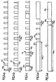
- An embodiment of a control circuit according to the invention shown in Fig. 1, comprises a load circuit 10, which runs between a positive supply voltage U batt and ground and in which a semiconductor switch designated as a whole is arranged, which is designed for example as a MOSFET, a dram Connection D is connected to the positive supply voltage U batt , a gate connection G is provided for driving and a source connection is connected to a load 14, for example an inductive load in the form of a motor in particular.
- This inductive load 14 is also a free-wheeling diode 16 connected in parallel, so that the load 14 and the parallel-connected free-wheeling diode 16 are connected on the one hand to the source terminal S of the semiconductor switch 12 and on the other hand are connected to ground.
- Control signal S generates the successive and control pulses separated by pulse pauses.
- This Control signal S is generated by a pulse generator 22 and a subsequent pulse shaper stage 24 is generated, the pulse generator 22 rectangular pulses generated, their steepness is determined by the pulse shaping stage 24, for example such that the rising and falling edges are sufficient are long delayed by the freewheeling diode 16 sufficient Give time to switch on or switch off.
- the pulse generator 22 preferably comprises an OR gate 26, two pulse signal generators 28 and 30 and a control computer 32 which controls the pulse signal generators 28 and 30 so that these in turn generate pulse signal trains P 1 and P 2 , which in the adder 26 form a pulse control signal PS can be added.
- the control computer 32 receives the via an input signal E. Information about the power with which the load 14 to be operated.
- the control computer based on the input signal E differentiates between a lower part-load range UT and an upper part-load range OT, preferably the lower partial load range UT with a power feed of 0% based on full load begins and in the partial load range T up to a partial load of for example 40% based on full load is sufficient.
- the upper part-load range OT which up to full power V, i.e. H. the performance of 100% is sufficient so that the entire partial load range T is without gaps from the lower part load range and the upper one Partial load range results.
- the control computer 32 controls the first pulse signal generator 28 in such a way that it generates a pulse signal train P 1 with a first frequency f 1 , the individual pulses PE 1 of each start at time intervals ⁇ t 1 that correspond to frequency f 1 .
- These individual pulses PE 1 have a pulse width PW 1 , which can be set by the control computer 32, while the frequency f 1 cannot be set for the sake of simplicity, but can be fixedly predefined to the first pulse signal generator 28.
- the pulse width PW 1 is set, as will be explained in detail later, in accordance with the power desired at the load.
- control computer 32 controls the second pulse signal generator 30, which generates a second pulse signal train P 2 , also shown in FIG. 3, the second pulse signal train P 2 generating individual pulses which follow one another at a second frequency f 2 and thus in a time interval ⁇ t 2 are generated in succession according to this second frequency f 2 .
- the frequency f 2 is at least ten times the frequency f 1 , preferably frequencies of the order of 10 kHz or several 10 kHz are selected at the frequency f 2 , while the frequencies f 1 are of the order of a few 100 Hz, so that preferably the frequency f 2 is on the order of one hundred times the frequency f 1 .
- the pulse width PW 2 of the individual pulses PE 2 of the second pulse signal generator 30 can also be set by the control computer 32, while the frequency of the second pulse signal generator is usually likewise predefined.
- the two pulse signal trains P 1 and P 2 are now linked together by the adder 26 or OR gate so that the result is a pulse control signal PS, which is the logical OR operation of the two pulse signal trains P 1 and P 2 represents, so that the pulse control signal PS shows once the individual pulses PE 1 of the first pulse signal train P 1 , since during the time during which the individual pulses PE 1 are present, the existence of the individual pulses PE 2 of the second pulse signal train P 2 is irrelevant, especially when the individual pulses PE 1 have a larger pulse width PW 1 than the individual pulses PE 2 of the second pulse signal train.
- the individual pulses PE 2 of the second pulse signal train P 2 occur in the pulse control signal PS.
- the pulse widths PW 1 of the individual pulses PE 1 of the first pulse signal train P 1 are generally larger than the pulse widths PW 2 of the individual pulses PE 2 of the second pulse signal train P 2 , a longer switching takes place each time the individual pulses PE 1 occur in the pulse control signal PS of the semiconductor switch 12 compared to switching on the semiconductor switch 12 when a single pulse PE 2 occurs from the second pulse signal train P 2 during the pulse pauses PP between the individual pulses PE 1 of the first pulse signal train P 1 .
- the pulse width PW 2 of the individual pulses PE 2 of the second pulse signal train P 2 is kept as small as possible, in contrast to the largest possible pulse width PW 1 of the individual pulses PE 1 of the first pulse signal train P 1 , since with increasing pulse width PW 1 of the individual pulses PE 1 of the first pulse signal train, the number of switch-on and switch-off processes can be reduced if the pulse width PW 1 extends over at least an interval ⁇ t 2 of the second pulse signal train P 2 and with increasing pulse width PW 1 of the individual pulses PE 1 of the first pulse signal train P 1, the total number of switch-on and switch-off operations per unit of time decreases, since within the time interval ⁇ t 1, the load 14 is continuously supplied for an increasing duration due to the control of the semiconductor switch 12.
- the pulse control signal PS based on the second pulse signal train P 2 with a variable pulse width PW 2 is generated in the lower partial load range UT.
- One such type of load 14 power control is as an example in Fig. 4 at several points of the partial load range T specified.
- the pulse width PW 2 is selected so that it corresponds to a quarter of the time interval ⁇ t 2 , which lies between the beginning of two successive individual pulses PE 2 of the second pulse signal train. If, as shown in FIG. 4b, a partial load of 40% is to be used, the pulse width PW 2 'of the pulse control signal, which is still composed of individual pulses PE 2 of the second pulse signal train P 2 , is increased.
- the pulse control signal PS shows on the one hand the individual pulses PE 2 with the pulse width PW 2 of the second pulse signal train P 2 , but additionally the individual pulses PE 1 with the pulse width PW 1 of the first pulse signal train P 1 , the individual pulses PE 2 of the second pulse signal train P 2 occurring only in the pulse pauses PP between successive individual pulses PE 1 of the first pulse signal train P 1 .
- both the pulse width PW 2 of the second pulse signal train P 2 and the pulse width PW 1 of the first pulse signal train P 1 can thus be controlled when the power to be made available to the load 14 is increased.
- the pulse width PW 1 of the individual pulses PE 1 of the first pulse signal train is preferably increased with increasing power made available to the load 14, while a variation of the pulse width PW 2 of the individual pulses PE 2 of the second pulse signal train occurs only for the finest possible power setting.
- the pulse width PW 1 of the individual pulses PE 1 of the first pulse signal train can be increased to such an extent that only one or a few individual pulses PE 2 occur in the pulse pause PP between successive individual pulses PE 1 .
- the power is essentially controlled by setting the pulse width PW 2 of the individual pulses PE 2 of the second pulse signal train.
- the upper one Partial load range is preferably the upper one Partial load range, as shown in Fig. 5, in a normal upper partial load range NOT divided, which for example ranges from 40% part load to 90% part load and into one highest upper part load range HOT, which is from 90% to 100% is enough.
- the pulse width PW 1 is no longer changed even when the power is increased, but there is a power control via the variation of the pulse width PW 2 a few individual pulses PE 1 of the second pulse signal train P 2 in the pulse pauses PP between successive individual pulses PE 1 in order to be able to carry out this control as precisely as possible.
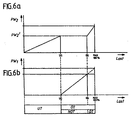
- This procedure is particularly simple in the normal upper part-load range NOT if, starting from the transition from the lower part-load range UT to the upper part-load range OT, the maximum pulse width PW 2 is maintained, which is present in the lower part-load range UT with maximum power feed-in, and then additionally the individual pulses PE 1 are added with the pulse width PW 1 of the first pulse signal train P 1 , which then replace one or more individual pulses PE 2 of the second pulse signal train P 2 , the entire power control in the normal upper part-load range preferably being carried out exclusively via the pulse width PW 1 with a constant pulse width PW 2 ' until the highest upper part load range HOT is reached.
- the pulse width PW 2 is increased in the lower part-load range UT, starting from a value essentially close to 0% to the value PW 2 ', at which a transition from the lower part-load range to the upper part-load range takes place, in the normal upper part-load range, As shown in FIG.
- the power control takes place exclusively by variation of the pulse width PW 1 until the highest upper part load range HOT is reached, in which the pulse width PW 1 is then kept constant at the maximum value of the normal upper part load range, while the power control exclusively Via the pulse width PW 2 , which for this purpose is increased beyond the value PW 2 ', which represents the maximum value during the transition from the lower part-load range to the upper part-load range.
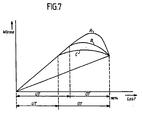
- the solution according to the invention makes it possible to reduce the overall thermal losses occurring in the control circuit according to the invention.
- 7 shows in the form of curve A the course of the heat losses when the entire power control takes place over the entire area by means of the second pulse signal train P 2 and the variation of the pulse width PW 2 .
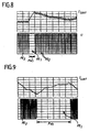
- the actual current I load at the load 14 is shown in Fig. 8 for a case similar to Fig. 4c, that is, for the case that the pulse width PW 1 is so small that it over a few individual pulses PE 2 of the second Pulse signal train P 2 extends.
- the current I load flowing through the load 14 rises during the single pulse PE 1 and then slowly drops, the current I load changing in accordance with the sequence of individual pulses PE 2 .
- the pulse width PW 1 of an individual pulse PE 1 is chosen to be larger, the course of the current I load over the load 14 is primarily dominated by the individual pulses PE 1 with the pulse width PW 1 and only to a small extent Dimensions of the individual pulses PE 2 in the pulse pauses of the first pulse signal train P 1 .
Abstract
Description
Die Erfindung betrifft eine Steuerschaltung zum leistungsgesteuerten Betreiben einer Last, umfassend einen in einem Laststromkreis wirksamen Halbleiterschalter und eine Ansteuerung für den Halbleiterschalter, welche zur Steuerung desselben in einem Teillastbereich ein Steuersignal, umfassend aufeinanderfolgende und durch Pulspausen getrennte Ansteuerpulse, erzeugt.The invention relates to a control circuit for power-controlled Operating a load, including one in one Load circuit effective semiconductor switch and a Control for the semiconductor switch, which for control the same in a partial load range comprising a control signal successive and separated by pulse pauses Control pulses generated.
Eine derartige Steuerschaltung ist aus dem Stand der Technik, beispielsweise der DE 197 02 949 A1 bekannt.Such a control circuit is from the prior art, known for example from DE 197 02 949 A1.
Bei einer derartigen Steuerschaltung wird ein Steuersignal erzeugt, welches Ansteuerpulse aufweist, die in einer definierten Frequenz aufeinanderfolgen und zum Steuern der Last pulsweitenmoduliert sind.In such a control circuit, a control signal generated, which has control pulses in a defined frequency and to control the Load are pulse width modulated.
Da bekanntermaßen das aufgrund der Ansteuerpulse erfolgende Aus- und Einschalten der Last, insbesondere bei einer induktiven Last mit Freilaufelement, d. h. beispielsweise Freilaufhalbleiterbauteil, zu erhöhten Verlusten und insbesondere einer verstärkten Wärmeerzeugung führt, ist die Aufgabe der vorliegenden Erfindung darin zu sehen, eine Steuerschaltung der gattungsgemäßen Art derart zu verbessern, daß die Wärmeerzeugung möglichst gering ist. As is known, this is due to the control pulses Switching the load off and on, especially with one inductive load with freewheel element, d. H. for example Freewheel semiconductor component, to increased losses and in particular leads to increased heat generation To see the object of the present invention in a To improve control circuit of the generic type in such a way that the heat generation is as low as possible.
Diese Aufgabe wird bei einer Steuerschaltung der eingangs
beschriebenen Art erfindungsgemäß dadurch gelöst, daß das
Steuersignal in einem oberen Teillastbereich ein erstes Pulssignal
mit mit einer ersten Pulsfrequenz aufeinanderfolgenden
ersten Einzelpulsen sowie in den Pulspausen des ersten Pulssignals
ein zweites Pulssignal mit mit einer zweiten Frequenz
aufeinanderfolgenden zweiten Einzelpulsen erzeugt und daß die
zweite Frequenz mindestens um einen Faktor 10 größer als die
erste Frequenz ist.This task is done in a control circuit of the beginning
described type according to the invention solved in that the
Control signal in an upper partial load range, a first pulse signal
with successive at a first pulse frequency
first individual pulses and in the pulse pauses of the first pulse signal
a second pulse signal with a second frequency
successive second individual pulses and that the
second frequency is at least a
Der Kern der vorliegenden Erfindung ist somit darin zu sehen, einerseits die Last, d. h. beispielsweise einen als induktive Last wirkenden Motor, durch das erste Pulssignal mit niedriger Frequenz so anzusteuern, daß durch dieses Pulssignal möglichst viel Leistung bei möglichst wenig Ein- und Ausschaltvorgängen der Last zugeführt werden kann, andererseits aber in den durch die niedrige Frequenz des ersten Pulssignals bedingten langen Pausen zwischen den Einzelpulsen mit dem zweiten Pulssignal mit hoher Frequenz ebenfalls noch Leistung zuzuführen, um die Nachteile des ausschließlichen Betreibens der Last mit nur dem ersten Pulssignal mit niedriger Frequenz zu vermeiden, wobei sich diese Nachteile insbesondere in einer mechanischen Geräuschentwicklung oder dem Entstehen mechanischer Resonanzen zeigen.The essence of the present invention is therefore to be seen in on the one hand the load, d. H. for example one as an inductive one Load-acting motor with the first pulse signal low frequency so that this pulse signal as much performance as possible with as little input and Switch-off operations of the load can be supplied, on the other hand but in the low frequency of the first Pulse signals caused long pauses between the individual pulses with the second pulse signal with a high frequency Deliver power to the cons of exclusive Operating the load with only the first pulse signal avoid low frequency, with these drawbacks especially in a mechanical noise development or show the emergence of mechanical resonances.
Hinsichtlich der Steuerung der Leistung, die der Last zugeführt werden soll, bestehen dabei die unterschiedlichsten Möglichkeiten. Eine Möglichkeit wäre die, die Frequenz des zweiten Pulssignals oder gegebenenfalls auch des ersten Pulssignals zu ändern. Regarding the control of the power supplied to the load there are many different types Possibilities. One possibility would be the frequency of the second pulse signal or possibly also the first pulse signal to change.
Da vorzugsweise jedoch beim gepulsten Betrieb einer Last zur Vermeidung von peripheren Störungseinflüssen mit definierten feststehenden Frequenzen gearbeitet wird, ist vorzugsweise vorgesehen, daß in dem oberen Teillastbereich mindestens eines der ersten und zweiten Pulssignale zur Leistungssteuerung pulsweitenmodulierbar ist, d. h., daß über die Variation der Pulsweite bei feststehender Frequenz des jeweiligen Pulssignals die der Last zugeführte Leistung gesteuert werden kann.However, since a load is preferably used for pulsed operation Avoidance of peripheral interference with defined fixed frequencies is preferred provided that at least in the upper part-load range one of the first and second pulse signals for power control is pulse width modulable, d. that is, over the Variation of the pulse width at a fixed frequency of the respective pulse signal the power supplied to the load can be controlled.
Besonders günstig ist es bei der erfindungsgemäßen Lösung, wenn in dem oberen Teillastbereich beide Pulssignale pulsweitenmodulierbar sind, so daß durch inkrementelle Verstellung der Pulsweite beider Pulssignale die gewünschte Präzision der Steuerung durch die Einstellung der Pulsweite desjenigen Pulssignals erreicht werden kann, dessen Inkremente die kleineren sind. Vorzugsweise ist dies das zweite Pulssignal, wobei mit dem zweiten Pulssignal auch eine Zunahme der Pulsweite des ersten Pulssignals durch abnehmende Pulsweite des zweiten Pulssignals reduzierbar ist.It is particularly favorable in the solution according to the invention if both pulse signals can be pulse-width modulated in the upper part-load range are so that by incremental adjustment the pulse width of both pulse signals the desired Control precision by adjusting the pulse width of the pulse signal can be reached, the Increments which are smaller. This is preferably that second pulse signal, with the second pulse signal also Increase in the pulse width of the first pulse signal by decreasing Pulse width of the second pulse signal can be reduced.
Bei einer besonders einfach arbeitenden Steuerschaltung ist vorzugsweise vorgesehen, daß im oberen Teillastbereich nur eines der Pulssignale pulsweitenmodulierbar ist.With a particularly simple control circuit preferably provided that only in the upper part of the load range one of the pulse signals can be pulse-width modulated.
In diesem Fall ist eine besonders präzise Leistungssteuerung dadurch durchführbar, daß der obere Teillastbereich in einen höchsten oberen Teillastbereich und einen normalen oberen Teillastbereich unterteilbar ist und daß in dem normalen oberen Teillastbereich die Einzelpulse des ersten Pulssignals pulsweitenmodulierbar sind und daß in dem höchsten oberen Teillastbereich die Einzelpulse des zweiten Pulssignals pulsweitenmodulierbar sind. In this case there is a particularly precise power control feasible in that the upper part-load range in a highest upper part load range and a normal upper one Partial load range can be divided and that in the normal upper partial load range the individual pulses of the first pulse signal are pulse width modulatable and that in the highest upper The individual pulses of the second pulse signal can be pulse width modulated in the partial load range are.
Insbesondere bei einer möglichst einfach arbeitenden Ausführungsform ist dabei vorgesehen, daß in dem normalen oberen Teillastbereich die Pulsweite der Einzelpulse des zweiten Pulssignals konstant ist und vorzugsweise in dem höchsten oberen Teillastbereich die Pulsweite der Einzelpulse des ersten Pulssignals konstant ist.Particularly in the case of an embodiment that is as simple as possible it is provided that in the normal upper Partial load range the pulse width of the individual pulses of the second Pulse signal is constant and preferably in the highest upper part load range the pulse width of the individual pulses of the first pulse signal is constant.
Beispielsweise wäre es denkbar, im Rahmen der erfindungsgemäßen Lösung, auch außerhalb des oberen Teillastbereichs mit einem Steuersignal zu arbeiten, das das erste Pulssignal und in den Pulspausen desselben das zweite Pulssignal zeigt.For example, it would be conceivable within the scope of the invention Solution, even outside the upper part load range to work with a control signal that is the first pulse signal and shows the second pulse signal during the pulse pauses.
Aus Gründen der Einfachheit der Steuerung und der ausreichenden Präzision ist es jedoch besonders günstig, wenn in einem unterhalb des oberen Teillastbereichs liegenden Teillastbereich das Steuersignal ein drittes Pulssignal mit einer dritten Frequenz umfaßt, die größer als die erste Frequenz ist, so daß die Einzelpulse des dritten Pulssignals in entsprechend geringen Zeitintervallen aufeinanderfolgen.For the sake of simplicity of control and sufficient However, precision is particularly beneficial if in one part load range below the upper part load range the control signal is a third pulse signal with a third frequency, which is greater than the first frequency is, so that the individual pulses of the third pulse signal in corresponding short time intervals follow each other.
Vorzugsweise sollte dabei die dritte Frequenz in derselben Größenordnung liegen wie die zweite Frequenz, so daß sowohl die zweite Frequenz als auch die dritte Frequenz deutlich über der ersten Frequenz liegen, um in dem unteren Teillastbereich eine möglichst geräuschfreie und resonanzfreie Ansteuerung der Last vornehmen zu können.The third frequency should preferably be in the same Order of magnitude are like the second frequency, so that both the second frequency as well as the third frequency clearly lie above the first frequency in the lower part-load range the most noise-free and resonance-free To be able to control the load.
Eine aufgrund der Einfachheit besonders günstige Lösung sieht vor, daß die dritte Frequenz und die zweite Frequenz ungefähr gleich groß sind, so daß also sowohl im unteren Teillastbereich als auch im oberen Teillastbereich die vorteilhaften Steuereigenschaften eines Pulssignals mit relativ hoher Pulsfrequenz ausgenützt werden können.A solution that is particularly favorable due to the simplicity before that the third frequency and the second frequency approximately are the same size, so that both in the lower Partial load range as well as in the upper part load range advantageous control properties of a pulse signal relatively high pulse frequency can be used.
Eine besonders günstige Lösung sieht vor, daß die dritte Frequenz mit der zweiten Frequenz identisch ist, so daß letztlich sowohl zum Betreiben der Last im unteren Teillastbereich als auch zum Betreiben der Last im oberen Teillastbereich stets mit derselben Frequenz gearbeitet werden kann und beim Übergang vom unteren Teillastbereich zum oberen Teillastbereich lediglich das zweite Pulssignal hinzu kommt.A particularly favorable solution provides that the third Frequency is identical to the second frequency, so that ultimately both for operating the load in the lower partial load range as well as for operating the load in the upper part-load range can always work with the same frequency and in the transition from the lower part-load range to the upper Part load range only the second pulse signal is added.
Zur Leistungssteuerung im unteren Teillastbereich ist dabei das dritte Pulssignal vorzugsweise ebenfalls pulsweitenmodulierbar.For power control in the lower part-load range the third pulse signal can also preferably be pulse width modulated.
Der Übergang von dem unteren Teillastbereich in den oberen Teillastbereich kann prinzipiell bei beliebigen Werten der Teillast liegen. Eine besonders vorteilhafte Lösung sieht vor, daß der Übergang von dem unteren Teillastbereich in den oberen Teillastbereich bei Teillastwerten zwischen ungefähr 20 % und ungefähr 50 %, jeweils bezogen auf Vollast, erfolgt.The transition from the lower part-load range to the upper Partial load range can in principle with any values of Partial load. A particularly advantageous solution sees before that the transition from the lower part load range in the upper part load range with part load values between approx 20% and approximately 50%, each based on full load.
Eine besonders günstige Lösung sieht vor, daß der Übergang von dem unteren Teillastbereich in den oberen Teillastbereich bei Teillastwerten von ungefähr 30 % bis ungefähr 40 % erfolgt.A particularly favorable solution provides that the transition from the lower part-load range to the upper part-load range at partial load values from approximately 30% to approximately 40% he follows.
Hinsichtlich der Unterschiede der zweiten Frequenz und der dritten Frequenz gegenüber der ersten Frequenz ist es - wie bereits ausgeführt - prinzipiell ausreichend, daß diese mindestens einen Faktor 10 betragen. Besonders günstig ist es jedoch, wenn die Frequenzunterschiede bei einem Faktor in der Größenordnung von 30 oder mehr, vorzugsweise in der Größenordnung von 100 oder mehr, liegen.Regarding the differences in the second frequency and the third frequency versus the first frequency it is - like already executed - in principle sufficient that this be at least a factor of 10. It is particularly cheap however, if the frequency differences are at a factor in the The order of 30 or more, preferably of the order of 100 or more.
Prinzipiell wäre es möglich, in dem Teillastbereich unterhalb der vollen Ansteuerung der Last mit weiteren Teillastbereichen, beispielsweise auch zwischen dem unteren Teillastbereich und dem oberen Teillastbereich, zu arbeiten. Aus Gründen der Einfachheit hat es sich jedoch als günstig erwiesen, wenn der obere Teillastbereich sich unmittelbar an den unteren Teillastbereich anschließt.In principle, it would be possible in the partial load range below full control of the load with further partial load ranges, for example between the lower part of the load range and the upper part-load range to work. Out However, for simplicity, it has proven to be cheap proven when the upper part-load range changes immediately connects the lower part of the load range.
Darüber hinaus wäre es noch denkbar, außerhalb des unteren und des oberen Teillastbereichs zusätzliche Teillastbereiche vorzusehen, in denen eine anders geartete Ansteuerung der Teillast erfolgen kann.In addition, it would still be conceivable outside of the lower one and the upper part-load range additional part-load ranges to provide in which a different type of control of the Partial load can take place.
Besonders günstig ist es jedoch, wenn der untere Teillastbereich und der obere Teillastbereich den gesamten Teillastbereich bis zur Vollast abdecken.However, it is particularly favorable if the lower partial load range and the upper part-load range the entire part-load range cover up to full load.
Hinsichtlich der Erzeugung der Steuersignale im Fall einer erfindungsgemäßen Steuerschaltung wurden keine näheren Angaben gemacht, insbesondere keine näheren Angaben zum Aufbau der Ansteuerung. So sieht eine vorteilhafte Lösung vor, daß die Ansteuerung einen Pulsgenerator und eine Pulsformerstufe aufweist, wobei der Pulsgenerator insbesondere ein im wesentlichen Rechteckpulse erzeugender Pulsgenerator sein kann, und die Pulsformerstufe dann beispielsweise die Flanken der Rechteckpulse derart formt, daß ausreichend lange Steuerzeiten für den Betrieb der Last, insbesondere einer induktiven Last mit Freilaufdiode, zur Verfügung stehen. With regard to the generation of the control signals in the case of a Control circuit according to the invention were no closer Information provided, in particular no further details on the Structure of the control. This is an advantageous solution before that the control a pulse generator and a pulse shaper has, the pulse generator in particular a pulse generator generating essentially rectangular pulses can be, and then the pulse shaper stage, for example, the The edges of the rectangular pulses are shaped in such a way that they are long enough Control times for the operation of the load, especially one inductive load with free-wheeling diode.
Besonders günstig ist es dabei, wenn die Pulsformerstufe aus den Rechteckpulsen im wesentlichen in den Flanken zeitlich verzögerte Anstiegs- und Abfallzeiten erzeugt.It is particularly favorable if the pulse shaper stage is off the rectangular pulses essentially in time in the flanks delayed rise and fall times.
Beispielsweise lassen sich derartige zeitlich verzögerte Anstiegs- und Abfallzeiten durch RC-Glieder der Pulsformerstufe erzeugen.For example, such can be delayed in time Rise and fall times through RC elements of the pulse shaper stage produce.
Hinsichtlich der Erzeugung des ersten Pulssignals und des in den Pulspausen des ersten Pulssignals auftretenden zweiten Pulssignals wurden bislang keine näheren Angaben gemacht. So sieht eine vorteilhafte Ausführungsform vor, daß das erste Pulssignal und das zweite Pulssignal als fortlaufende Einzelpulse aufweisende Pulssignalzüge mit konstanter Frequenz erzeugbar sind und daß aus den Pulssignalzügen durch ODER-Verknüpfung das Steuersignal für den oberen Teillastbereich entsteht.With regard to the generation of the first pulse signal and in the pulse pauses of the second pulse occurring second No pulse signals have so far been given. So An advantageous embodiment provides that the first Pulse signal and the second pulse signal as continuous individual pulses having pulse signal trains with constant frequency can be generated and that from the pulse signal trains by OR operation the control signal for the upper part load range arises.
Eine derartige Erzeugung des Steuersignals kann auch dann beibehalten werden, wenn das Steuersignal für den unteren Teillastbereich erzeugt werden soll. In diesem Fall wird der Einfachheit halber die Pulsweite des ersten Pulssignals auf im wesentlichen 0 reduziert.Such a generation of the control signal can then also be maintained when the control signal for the lower Part load range should be generated. In this case the For the sake of simplicity, the pulse width of the first pulse signal essentially reduced to 0.
Darüber hinaus wird die eingangs genannte Aufgabe auch durch ein Verfahren zum leistungsgesteuerten Betreiben einer Last mittels einer Steuerschaltung, umfassend einen in einem Laststromkreis wirksamen Halbleiterschalter und eine Ansteuerung für den Halbleiterschalter, welche zur Steuerung desselben in einem Teillastbereich ein Steuersignal umfassend aufeinanderfolgende und durch Pulspausen getrennte Ansteuerpulse erzeugt, erfindungsgemäß dadurch gelöst, daß in einem oberen Teillastbereich das Steuersignal so erzeugt wird, daß es ein erstes Pulssignal mit mit einer Pulsfrequenz aufeinanderfolgenden Einzelpulsen sowie in den Pulspausen des ersten Pulssignals ein zweites Pulssignal mit mit einer zweiten Frequenz aufeinanderfolgenden Einzelpulsen aufweist und daß die zweite Frequenz mindestens um einen Faktor 10 größer als die erste Frequenz ist.In addition, the task mentioned at the beginning is also accomplished by a method for power-controlled operation of a load by means of a control circuit comprising one in a load circuit effective semiconductor switch and a control for the semiconductor switch, which for controlling the same in a control signal comprising a successive partial load range and control pulses separated by pulse pauses generated, solved according to the invention in that in an upper Partial load range, the control signal is generated so that it is a first pulse signal with successive pulses Individual pulses as well as in the pulse pauses of the first Pulse signal a second pulse signal with a second Frequency has consecutive individual pulses and that the second frequency is at least a factor of 10 greater than is the first frequency.
Besonders günstig ist es dabei, wenn in dem oberen Teillastbereich die Leistungssteuerung durch Pulsweitenmodulation mindestens eines der ersten und zweiten Pulssignale durchgeführt wird, wobei vorzugsweise die Frequenz des ersten Pulssignals und des zweiten Pulssignals konstant gehalten wird.It is particularly favorable if in the upper part-load range power control through pulse width modulation performed at least one of the first and second pulse signals , preferably the frequency of the first Pulse signal and the second pulse signal kept constant becomes.
Eine hinsichtlich der Variationsmöglichkeit besonders günstige Lösung sieht dabei vor, daß zur Leistungssteuerung die Pulsweite beider Pulssignale moduliert wird.One particularly with regard to the possibility of variation cheap solution provides that for power control the pulse width of both pulse signals is modulated.
Aus Gründen der Einfachheit ist es jedoch günstig, wenn nur die Pulsweite eines der Pulssignale moduliert wird, während das andere der Pulssignale konstant gehalten wird.For the sake of simplicity, however, it is convenient if only the pulse width of one of the pulse signals is modulated while the other of the pulse signals is kept constant.
Ferner ist es für eine besonders präzise Steuerung von Vorteil, wenn der obere Teillastbereich in einen höchsten oberen Teillastbereich und einen normalen oberen Teillastbereich aufgeteilt wird.Furthermore, it is advantageous for a particularly precise control if the upper part load range is in a highest upper Part load range and a normal upper part load range is divided.
Vorzugsweise wird in dem normalen oberen Teillastbereich das erste Pulssignal hinsichtlich der Pulsweite zur Leistungssteuerung moduliert, während in dem höchsten oberen Teillastbereich das zweite Pulssignal zur Steuerung der Leistung moduliert wird. Preferably in the normal upper part load range first pulse signal with regard to the pulse width for power control modulated while in the highest upper part load range the second pulse signal to control the power is modulated.
Der Einfachheit halber bleibt das jeweils andere Pulssignal dabei hinsichtlich seiner Pulsweite konstant.For the sake of simplicity, the other pulse signal remains constant with regard to its pulse width.
Darüber hinaus ist es zur Steuerung der Leistung außerhalb des oberen Teillastbereichs von Vorteil, wenn unterhalb des oberen Teillastbereichs ein Steuersignal erzeugt wird, welches ein drittes Pulssignal mit einer dritten Frequenz umfaßt, die größer ist als die erste Frequenz.It is also used to control performance outside of the upper partial load range is advantageous if below the a control signal is generated in the upper part of the load range, which is a third pulse signal with a third frequency which is greater than the first frequency.
Dabei ist vorzugsweise die dritte Frequenz ebenfalls so gewählt, daß sie in derselben Größenordnung wie die zweite Frequenz liegt.The third frequency is also preferably the same chosen to be of the same order of magnitude as the second Frequency is.
Aus Gründen der Einfachheit ist es jedoch besonders günstig, wenn die dritte Frequenz mit der zweiten Frequenz identisch ist.However, for the sake of simplicity, it is particularly convenient if the third frequency is identical to the second frequency is.
Ferner ist es zur Leistungssteuerung in dem unteren Teillastbereich ebenfalls von Vorteil, wenn das dritte Pulssignal hinsichtlich seiner Pulsweite moduliert wird, wobei insbesondere die Frequenz, mit welcher die Einzelpulse aufeinanderfolgen, beim dritten Pulssignal ebenfalls konstant gehalten wird.It is also for power control in the lower part load range also advantageous if the third pulse signal is modulated with regard to its pulse width, in particular the frequency with which the individual pulses follow one another, also constant at the third pulse signal is held.
Hinsichtlich der Lage des oberen Teillastbereichs und des unteren Teillastbereichs relativ zueinander wurden bislang ebenfalls keine spezifischen Angaben gemacht. Beispielsweise könnten der obere Teillastbereich und der untere Teillastbereich noch voneinander getrennt sein. Besonders günstig ist es jedoch, wenn der obere Teillastbereich unmittelbar an den unteren Teillastbereich anschließt. With regard to the location of the upper part-load range and lower part load range relative to each other so far also no specific information given. For example could be the upper part load range and the lower part load range still be separated from each other. Is particularly cheap it, however, if the upper part of the load is directly connected to the connects the lower part of the load range.
Ferner ist vorzugsweise aus Gründen der Einfachheit vorgesehen, daß der untere Teillastbereich und der obere Teillastbereich den gesamten Teillastbereich bis zur Vollast abdecken.Furthermore, for reasons of simplicity, that the lower part load range and the upper part load range the entire partial load range up to full load cover.
Um bei dem erfindungsgemäßen Verfahren das Steuersignal möglichst einfach erzeugen zu können, ist vorzugsweise vorgesehen, daß das erste Pulssignal und zweite Pulssignal als fortlaufende Pulssignalzüge mit konstanter Frequenz erzeugt werden und durch ODER-Verknüpfung aus den beiden Pulssignalzügen das Steuersignal im oberen Teillastbereich erzeugt wird.To the control signal in the inventive method To be able to generate as simply as possible is preferably provided that the first pulse signal and second pulse signal as continuous pulse signal trains with constant frequency generated be and by OR-combination of the two pulse signal trains generates the control signal in the upper part-load range becomes.
In gleicher Weise besteht auch die Möglichkeit, im unteren Teillastbereich das Steuersignal zu erzeugen, wobei die Pulsweite dabei im wesentlichen auf 0 gehalten wird.In the same way there is also the possibility in the lower To generate part of the control signal, the pulse width is essentially kept at 0.
Weitere Merkmale und Vorteile der Erfindung sind Gegenstand der nachfolgenden Beschreibung sowie der zeichnerischen Darstellung eines Ausführungsbeispiels. In der Zeichnung zeigen:
- Fig. 1
- eine schematische Darstellung eines ersten Ausführungsbeispiels einer erfindungsgemäßen Steuerschaltung;
- Fig. 2
- eine schematische Darstellung der Aufteilung des Teillastbereichs in einen unteren Teillastbereich und einen oberen Teillastbereich;
- Fig. 3
- eine schematische Darstellung der Erzeugung eines Pulssteuersignals im Rahmen der erfindungsgemäßen Lösung aus einem ersten Pulssignalzug und einem zweiten Pulssignalzug durch ODER-Verknüpfung;
- Fig. 4
- eine exemplarische Darstellung des Steuersignals bei verschiedenen Teillastwerten im Rahmen der erfindungsgemäßen Lösung;
- Fig. 5
- eine schematische Darstellung der Aufteilung des oberen Teillastbereichs in einen normalen oberen Teillastbereich und einen höchsten oberen Teillastbereich;
- Fig. 6
- eine schematische Darstellung einer Variante des ersten Ausführungsbeispiels, bei welcher stets lediglich eines der Pulssignale pulsweitenmoduliert wird, während das andere nicht pulsweitenmoduliert wird;
- Fig. 7
- eine schematische Darstellung der erfindungsgemäß möglichen Reduzierung der erzeugten Wärme;
- Fig. 8
- eine Darstellung eines tatsächlichen Steuersignals mit dem entsprechenden über eine induktive Last fließenden Strom bei geringer Pulsweite des ersten Pulssignals und
- Fig. 9
- eine Darstellung eines tatsächlichen Steuersignals mit großer Pulsweite und dementsprechenden Strom durch eine induktive Last mit Freilaufdiode.
- Fig. 1
- a schematic representation of a first embodiment of a control circuit according to the invention;
- Fig. 2
- a schematic representation of the division of the partial load range into a lower partial load range and an upper partial load range;
- Fig. 3
- a schematic representation of the generation of a pulse control signal in the context of the inventive solution from a first pulse signal train and a second pulse signal train by OR operation;
- Fig. 4
- an exemplary representation of the control signal at different partial load values within the framework of the solution according to the invention;
- Fig. 5
- a schematic representation of the division of the upper part load range into a normal upper part load range and a highest upper part load range;
- Fig. 6
- a schematic representation of a variant of the first embodiment, in which only one of the pulse signals is always pulse width modulated, while the other is not pulse width modulated;
- Fig. 7
- a schematic representation of the possible reduction of the heat generated according to the invention;
- Fig. 8
- a representation of an actual control signal with the corresponding current flowing over an inductive load with a small pulse width of the first pulse signal and
- Fig. 9
- a representation of an actual control signal with a large pulse width and corresponding current through an inductive load with free-wheeling diode.
Ein Ausführungsbeispiel einer erfindungsgemäßen Steuerschaltung,
dargestellt in Fig. 1, umfaßt einen Laststromkreis
10, welcher zwischen einer positiven Speisespannung Ubatt und
Masse verläuft und in welchem ein als Ganzes mit 12 bezeichneter
Halbleiterschalter angeordnet ist, welcher beispielsweise
als MOSFET ausgebildet ist, wobei ein Dram-Anschluß D
mit der positiven Speisespannung Ubatt verbunden ist, ein
Gate-Anschluß G zum Ansteuern vorgesehen ist und ein Source-Anschluß
mit einer Last 14, beispielsweise einer induktiven
Last in Form insbesondere eines Motors, verbunden ist. Dieser
induktiven Last 14 ist ferner eine Freilaufdiode 16 parallelgeschaltet,
so daß die Last 14 und die parallelgeschaltete
Freilaufdiode 16 einerseits mit dem Source-Anschluß S des
Halbleiterschalters 12 verbunden sind und andererseits auf
Masse liegen.An embodiment of a control circuit according to the invention, shown in Fig. 1, comprises a
Zum Ansteuern des Halbleiterschalters 12 ist im Fall des
MOSFET-Halbleiterschalters der Gate-Anschluß G mit einer
Ansteuerung 20 verbunden, die ein dem Gate-Anschluß G zugeführtes
Steuersignal S erzeugt, das aufeinanderfolgende und
durch Pulspausen getrennte Ansteuerpulse umfaßt. Dieses
Steuersignal S wird durch einen Pulsgenerator 22 und eine
nachfolgende Pulsformerstufe 24 erzeugt, wobei der Pulsgenerator
22 Rechteckpulse generiert, deren Flankensteilheit
durch die Pulsformerstufe 24 festgelegt wird, beispielsweise
derart, daß die Anstiegs- und Abstiegsflanken ausreichend
lange verzögert sind, um der Freilaufdiode 16 ausreichend
Zeit zum Einschalten bzw. Ausschalten zu geben.To control the
Vorzugsweise umfaßt der Pulsgenerator 22 ein ODER-Gatter 26,
zwei Pulssignalgeneratoren 28 und 30 und einen Steuerrechner
32, welcher die Pulssignalgeneratoren 28 und 30 ansteuert,
so daß diese ihrerseits Pulssignalzüge P1 bzw. P2 erzeugen,
welche in dem Addierglied 26 zu einem Pulssteuersignal PS
addiert werden.The
Der Steuerrechner 32 erhält über ein Eingangssignal E die
Information darüber, mit welcher Leistung die Last 14
betrieben werden soll.The
Intern wird, wie in Fig. 2 dargestellt, in dem Steuerrechner ausgehend von dem Eingangssignal E differenziert zwischen einem unteren Teillastbereich UT und einem oberen Teillastbereich OT, wobei vorzugsweise der untere Teillastbereich UT bei einer Leistungseinspeisung von 0 % bezogen auf Vollast beginnt und im Teillastbereich T bis zu einer Teillast von beispielsweise 40 % bezogen auf Vollast reicht. Unmittelbar daran schließt sich dann der obere Teillastbereich OT an, welcher bis zur vollen Leistung V, d. h. der Leistung von 100 % reicht, so daß der gesamte Teillastbereich T sich lückenlos aus dem unteren Teillastbereich und dem oberen Teillastbereich ergibt.Internally, as shown in Fig. 2, in the control computer based on the input signal E differentiates between a lower part-load range UT and an upper part-load range OT, preferably the lower partial load range UT with a power feed of 0% based on full load begins and in the partial load range T up to a partial load of for example 40% based on full load is sufficient. Right away this is followed by the upper part-load range OT, which up to full power V, i.e. H. the performance of 100% is sufficient so that the entire partial load range T is without gaps from the lower part load range and the upper one Partial load range results.
Es ist aber auch denkbar, den Teillastbereich so zu wählen, daß dieser weder bei 0 % beginnt noch bei 100 % endet, sondern zwischen diesen Werten liegt.However, it is also conceivable to choose the partial load range in such a way that it neither starts at 0% nor ends at 100%, but lies between these values.
Ergibt sich aus dem Eingangssignal E, daß die Last 14 im
oberen Teillastbereich OT betrieben werden soll, so steuert
der Steuerrechner 32 den ersten Pulssignalgenerator 28 derart
an, daß dieser einen Pulssignalzug P1 mit einer ersten
Frequenz f1 erzeugt, dessen Einzelpulse PE1 jeweils nach
Zeitintervallen Δt1 starten, die der Frequenz f1 entsprechen. If it follows from the input signal E that the
Diese Einzelpulse PE1 haben dabei eine Pulsweite PW1, welche
durch den Steuerrechner 32 einstellbar ist, während die
Frequenz f1 der Einfachheit halber nicht einstellbar ist,
sondern fest dem ersten Pulssignalgenerator 28 vorgebbar ist.These individual pulses PE 1 have a pulse width PW 1 , which can be set by the
Die Einstellung der Pulsweite PW1 erfolgt, wie nachher im einzelnen dargelegt, entsprechend der an der Last gewünschten Leistung.The pulse width PW 1 is set, as will be explained in detail later, in accordance with the power desired at the load.
Ferner steuert der Steuerrechner 32 den zweiten Pulssignalgenerator
30 an, welcher einen zweiten Pulssignalzug P2,
ebenfalls dargestellt in Fig. 3, erzeugt, wobei der zweite
Pulssignalzug P2 Einzelpulse erzeugt, die mit einer zweiten
Frequenz f2 aufeinanderfolgen und somit in einem Zeitintervall
Δt2 entsprechend dieser zweiten Frequenz f2 aufeinanderfolgend
erzeugt werden.Furthermore, the
Dabei beträgt die Frequenz f2 mindestens das Zehnfache der Frequenz f1, vorzugsweise werden bei der Frequenz f2 Frequenzen in der Größenordnung von 10 kHz oder mehreren 10 kHz gewählt, während die Frequenzen f1 in der Größenordnung von einigen 100 Hz liegen, so daß vorzugsweise die Frequenz f2 größenordnungsmäßig das Einhundertfache der Frequenz f1 beträgt.The frequency f 2 is at least ten times the frequency f 1 , preferably frequencies of the order of 10 kHz or several 10 kHz are selected at the frequency f 2 , while the frequencies f 1 are of the order of a few 100 Hz, so that preferably the frequency f 2 is on the order of one hundred times the frequency f 1 .
Auch die Pulsweite PW2 der Einzelpulse PE2 des zweiten Pulssignalgenerators
30 ist durch den Steuerrechner 32 einstellbar,
während die Frequenz des zweiten Pulssignalgenerators
üblicherweise ebenfalls fest vorgegeben ist.The pulse width PW 2 of the individual pulses PE 2 of the second
Wie in Fig. 3 dargestellt, werden nun die beiden Pulssignalzüge
P1 und P2 durch das Addierglied 26 oder ODER-Gatter miteinander
so verknüpft, daß als Ergebnis ein
Pulssteuersignal PS entsteht, das die logische ODER-Verknüpfung
beider Pulssignalzüge P1 und P2 darstellt, so daß
das Pulssteuersignal PS einmal die Einzelpulse PE1 des ersten
Pulssignalzuges P1 zeigt, da während der Zeit, während der
die Einzelpulse PE1 vorliegen, die Existenz der Einzelpulse
PE2 des zweiten Pulssignalzuges P2 unerheblich ist,
insbesondere dann, wenn die Einzelpulse PE1 eine größere
Pulsweite PW1 aufweisen als die Einzelpulse PE2 des zweiten
Pulssignalzuges.As shown in Fig. 3, the two pulse signal trains P 1 and P 2 are now linked together by the
Während der Pulspausen PP zwischen den Einzelpulsen PE1 des ersten Pulssignalzuges P1 treten dann jedoch in dem Pulssteuersignal PS die Einzelpulse PE2 des zweiten Pulssignalzuges P2 auf.However, during the pulse pauses PP between the individual pulses PE 1 of the first pulse signal train P 1 , the individual pulses PE 2 of the second pulse signal train P 2 occur in the pulse control signal PS.
Da vorzugsweise die Pulsweiten PW1 der Einzelpulse PE1 des
ersten Pulssignalzuges P1 in der Regel größer sind als die
Pulsweiten PW2 der Einzelpulse PE2 des zweiten Pulssignalzugs
P2, erfolgt jeweils bei Auftreten der Einzelpulse PE1 in dem
Pulssteuersignal PS ein längeres Durchschalten des Halbleiterschalters
12 im Vergleich zum Durchschalten des Halbleiterschalters
12 beim Auftreten eines Einzelpulses PE2 aus
dem zweiten Pulssignalzug P2 während der Pulspausen PP
zwischen den Einzelpulsen PE1 des ersten Pulssignalzugs P1.Since preferably the pulse widths PW 1 of the individual pulses PE 1 of the first pulse signal train P 1 are generally larger than the pulse widths PW 2 of the individual pulses PE 2 of the second pulse signal train P 2 , a longer switching takes place each time the individual pulses PE 1 occur in the pulse control signal PS of the
In dem oberen Teillastbereich OT besteht nunmehr die Möglichkeit,
die der Last 14 zugeführte Leistung dadurch zu steuern,
daß entweder die Pulsweite PW1 der Einzelpulse PE1 des ersten
Pulssignalzuges P1 oder die Pulsweite PW2 der Einzelpulse PE2
des zweiten Pulssignalzuges P2 oder die Pulsweiten PW1 und PW2
beider Pulssignalzüge P1 und P2 variiert werden, so daß die
der Last 14 zuzuführende Leistung beliebig fein und präzise
einstellbar ist. In the upper part-load range OT there is now the possibility to control the power supplied to the
Vorzugsweise wird jedoch im oberen Teillastbereich OT so
gearbeitet, daß die Pulsweite PW2 der Einzelpulse PE2 des
zweiten Pulssignalzuges P2 möglichst klein gehalten wird, im
Gegensatz zu einer möglichst großen Pulsweite PW1 der Einzelpulse
PE1 des ersten Pulssignalzuges P1, da mit steigender
Pulsweite PW1 der Einzelpulse PE1 des ersten Pulssignalzuges
die Zahl der Ein- und Ausschaltvorgänge reduziert werden
kann, wenn sich die Pulsweite PW1 über mindestens ein Intervall
Δt2 des zweiten Pulssignalzuges P2 erstreckt und mit
zunehmender Pulsweite PW1 der Einzelpulse PE1 des ersten
Pulssignalzuges P1 insgesamt die Zahl der Ein- und Ausschaltvorgänge
pro Zeiteinheit abnimmt, da innerhalb des Zeitintervalls
Δt1 für eine immer größere Dauer die Last 14 aufgrund
des Durchsteuerns des Halbleiterschalters 12 dauergespeist
ist.Preferably, however, in the upper part-load range OT, the pulse width PW 2 of the individual pulses PE 2 of the second pulse signal train P 2 is kept as small as possible, in contrast to the largest possible pulse width PW 1 of the individual pulses PE 1 of the first pulse signal train P 1 , since with increasing pulse width PW 1 of the individual pulses PE 1 of the first pulse signal train, the number of switch-on and switch-off processes can be reduced if the pulse width PW 1 extends over at least an interval Δt 2 of the second pulse signal train P 2 and with increasing pulse width PW 1 of the individual pulses PE 1 of the first pulse signal train P 1, the total number of switch-on and switch-off operations per unit of time decreases, since within the time interval Δt 1, the
Dagegen wird vorzugsweise im unteren Teillastbereich UT nur das Pulssteuersignal PS basierend auf dem zweiten Pulssignalzug P2 mit variabler Pulsweite PW2 erzeugt.In contrast, preferably only the pulse control signal PS based on the second pulse signal train P 2 with a variable pulse width PW 2 is generated in the lower partial load range UT.
Eine derartige Art der Leistungssteuerung der Last 14 ist
exemplarisch in Fig. 4 an mehreren Stellen des Teillastbereichs
T angegeben.One such type of
So ist beispielsweise in Fig. 4a bei einem Teillastbereich von 25 % bezogen auf Vollast die Pulsweite PW2 so gewählt, daß sie einem Viertel des Zeitintervalls Δt2 entspricht, das zwischen dem Anfang zweier aufeinanderfolgender Einzelpulse PE2 des zweiten Pulssignalzuges liegt. Soll, wie in Fig. 4b dargestellt, mit einer Teillast von 40 % gearbeitet werden, so ist die Pulsweite PW2' des Pulssteuersignals, das immer noch aus Einzelpulsen PE2 des zweiten Pulssignalzuges P2 zusammengesetzt ist, vergrößert.For example, in Fig. 4a with a partial load range of 25% based on full load, the pulse width PW 2 is selected so that it corresponds to a quarter of the time interval Δt 2 , which lies between the beginning of two successive individual pulses PE 2 of the second pulse signal train. If, as shown in FIG. 4b, a partial load of 40% is to be used, the pulse width PW 2 'of the pulse control signal, which is still composed of individual pulses PE 2 of the second pulse signal train P 2 , is increased.
Wird nun, wie in Fig. 4c dargestellt, vom unteren Teillastbereich in den oberen Teillastbereich übergegangen, der beispielsweise bei ungefähr 40 % beginnt, so zeigt das Pulssteuersignal PS, wie in Fig. 4c exemplarisch dargestellt, einerseits die Einzelpulse PE2 mit der Pulsweite PW2 des zweiten Pulssignalzuges P2, jedoch zusätzlich die Einzelpulse PE1 mit der Pulsweite PW1 des ersten Pulssignalzuges P1, wobei die Einzelpulse PE2 des zweiten Pulssignalzuges P2 nur in den Pulspausen PP zwischen aufeinanderfolgenden Einzelpulsen PE1 des ersten Pulssignalzuges P1 auftreten.If, as shown in FIG. 4c, a transition is made from the lower partial load range to the upper partial load range, which begins, for example, at approximately 40%, then the pulse control signal PS, as shown by way of example in FIG. 4c, shows on the one hand the individual pulses PE 2 with the pulse width PW 2 of the second pulse signal train P 2 , but additionally the individual pulses PE 1 with the pulse width PW 1 of the first pulse signal train P 1 , the individual pulses PE 2 of the second pulse signal train P 2 occurring only in the pulse pauses PP between successive individual pulses PE 1 of the first pulse signal train P 1 .
In dem oberen Teillastbereich OT kann somit bei Erhöhung der
der Last 14 zur Verfügung zu stellenden Leistung sowohl die
Pulsweite PW2 des zweiten Pulssignalzuges P2 als auch die
Pulsweite PW1 des ersten Pulssignalzuges P1 gesteuert werden.
Vorzugsweise wird die Pulsweite PW1 der Einzelpulse PE1 des
ersten Pulssignalzuges mit zunehmender der Last 14 zur Verfügung
gestellter Leistung vergrößert, während eine Variation
der Pulsweite PW2 der Einzelpulse PE2 des zweiten Pulssignalzuges
nur zur möglichst feinstufigen Leistungseinstellung
erfolgt.In the upper partial load range OT, both the pulse width PW 2 of the second pulse signal train P 2 and the pulse width PW 1 of the first pulse signal train P 1 can thus be controlled when the power to be made available to the
Die Steigerung der Pulsweite PW1 der Einzelpulse PE1 des ersten Pulssignalzuges kann so weit erfolgen, daß in der Pulspause PP zwischen aufeinanderfolgenden Einzelpulsen PE1 nur noch einer oder einige wenige Einzelpulse PE2 auftreten. The pulse width PW 1 of the individual pulses PE 1 of the first pulse signal train can be increased to such an extent that only one or a few individual pulses PE 2 occur in the pulse pause PP between successive individual pulses PE 1 .
Um nahe der vollen Leistung möglichst präzise steuern zu können, ist vorzugsweise vorgesehen, daß im Bereich nahe Vollast im wesentlichen die Leistungssteuerung durch Einstellung der Pulsweite PW2 der Einzelpulse PE2 des zweiten Pulssignalzuges erfolgt.In order to be able to control as close as possible to the full power, it is preferably provided that in the area near full load the power is essentially controlled by setting the pulse width PW 2 of the individual pulses PE 2 of the second pulse signal train.
Um insbesondere nahe des Vollastbereichs möglichst präzise die Leistung steuern zu können, wird vorzugsweise der obere Teillastbereich, wie in Fig. 5 dargestellt, in einen normalen oberen Teillastbereich NOT unterteilt, welcher beispielsweise von 40 % Teillast bis 90 % Teillast reicht und in einen höchsten oberen Teillastbereich HOT, welcher von 90 % bis 100 % reicht.To be as precise as possible, especially near the full-load range to be able to control the output is preferably the upper one Partial load range, as shown in Fig. 5, in a normal upper partial load range NOT divided, which for example ranges from 40% part load to 90% part load and into one highest upper part load range HOT, which is from 90% to 100% is enough.
In diesem höchsten oberen Teillastbereich HOT wird ausgehend von dem Wert der Pulsweite PW1 der Einzelpulse PE1 des ersten Pulssignalzuges bei 90 % auch bei einer Leistungserhöhung die Pulsweite PW1 nicht mehr geändert, sondern es folgt eine Leistungssteuerung über die Variation der Pulsweite PW2 der wenigen Einzelpulse PE1 des zweiten Pulssignalzuges P2 in den Pulspausen PP zwischen aufeinanderfolgenden Einzelpulsen PE1, um diese Steuerung möglichst präzise vornehmen zu können.In this highest upper part-load range HOT, based on the value of the pulse width PW 1 of the individual pulses PE 1 of the first pulse signal train at 90%, the pulse width PW 1 is no longer changed even when the power is increased, but there is a power control via the variation of the pulse width PW 2 a few individual pulses PE 1 of the second pulse signal train P 2 in the pulse pauses PP between successive individual pulses PE 1 in order to be able to carry out this control as precisely as possible.
Prinzipiell wäre dabei in dem normalen oberen Teillastbereich NOT sowohl eine Variation der Pulsweite PW1 als auch eine Variation der Pulsweite PW2 zur Leistungseinstellung möglich.In principle, both a variation of the pulse width PW 1 and a variation of the pulse width PW 2 for power setting would be possible in the normal upper partial load range NOT.
Besonders einfach ist diese Vorgehensweise im normalen oberen Teillastbereich NOT dann, wenn ausgehend vom Übergang vom unteren Teillastbereich UT in den oberen Teillastbereich OT die maximale Pulsweite PW2 beibehalten wird, die bei maximaler Leistungseinspeisung Last im unteren Teillastbereich UT vorliegt und dann zusätzlich die Einzelpulse PE1 mit der Pulsweite PW1 des ersten Pulssignalzuges P1 hinzugefügt werden, die dann einen oder mehrere Einzelpulse PE2 des zweiten Pulssignalzuges P2 ersetzen, wobei die gesamte Leistungssteuerung im normalen oberen Teillastbereich vorzugsweise ausschließlich über die Pulsweite PW1 bei konstanter Pulsweite PW2' erfolgt, bis der höchste obere Teillastbereich HOT erreicht ist.This procedure is particularly simple in the normal upper part-load range NOT if, starting from the transition from the lower part-load range UT to the upper part-load range OT, the maximum pulse width PW 2 is maintained, which is present in the lower part-load range UT with maximum power feed-in, and then additionally the individual pulses PE 1 are added with the pulse width PW 1 of the first pulse signal train P 1 , which then replace one or more individual pulses PE 2 of the second pulse signal train P 2 , the entire power control in the normal upper part-load range preferably being carried out exclusively via the pulse width PW 1 with a constant pulse width PW 2 ' until the highest upper part load range HOT is reached.
Eine derartige Vorgehensweise ist in Fig. 6a und b dargestellt. Gemäß Fig. 6a wird die Pulsweite PW2 im unteren Teillastbereich UT, beginnend von einem Wert im wesentlichen nahe 0 % bis zum Wert PW2' erhöht, bei welchem ein Übergang vom unteren Teillastbereich in den oberen Teillastbereich erfolgt, wobei im normalen oberen Teillastbereich, wie in Fig. 6 dargestellt, die Leistungssteuerung ausschließlich durch Variation der Pulsweite PW1 erfolgt bis zum Erreichen des höchsten oberen Teillastbereichs HOT, in welchem wiederum die Pulsweite PW1 dann auf dem maximalen Wert des normalen oberen Teillastbereichs konstant gehalten wird, während die Leistungssteuerung ausschließlich über die Pulsweite PW2 erfolgt, die hierzu über den Wert PW2', welcher den maximalen Wert beim Übergang vom unteren Teillastbereich in den oberen Teillastbereich repräsentiert, hinaus erhöht wird.Such a procedure is shown in Fig. 6a and b. 6a, the pulse width PW 2 is increased in the lower part-load range UT, starting from a value essentially close to 0% to the value PW 2 ', at which a transition from the lower part-load range to the upper part-load range takes place, in the normal upper part-load range, As shown in FIG. 6, the power control takes place exclusively by variation of the pulse width PW 1 until the highest upper part load range HOT is reached, in which the pulse width PW 1 is then kept constant at the maximum value of the normal upper part load range, while the power control exclusively Via the pulse width PW 2 , which for this purpose is increased beyond the value PW 2 ', which represents the maximum value during the transition from the lower part-load range to the upper part-load range.
Wie in Fig. 7 dargestellt, erlaubt es die erfindungsgemäße Lösung, die insgesamt bei der erfindungsgemäßen Steuerschaltung anfallenden thermischen Verluste zu reduzieren. Fig. 7 zeigt in Form der Kurve A den Verlauf der Wärmeverluste dann, wenn die gesamte Leistungssteuerung über den gesamten Bereich mittels des zweiten Pulssignalzuges P2 und der Variation der Pulsweite PW2 erfolgt. As shown in FIG. 7, the solution according to the invention makes it possible to reduce the overall thermal losses occurring in the control circuit according to the invention. 7 shows in the form of curve A the course of the heat losses when the entire power control takes place over the entire area by means of the second pulse signal train P 2 and the variation of the pulse width PW 2 .
Wird hingegen, wie durch die Kurve B dargestellt, im oberen Teillastbereich OT mit einer Kombination aus den Einzelpulsen PE1 des ersten Pulssignalzuges P1 und den Einzelpulsen PE2 des zweiten Pulssignalzuges P2 die Leistung gesteuert, so lassen sich die Wärmeverluste deutlich reduzieren. Noch deutlicher lassen sich die Wärmeverluste reduzieren, wenn der Übergang vom unteren Teillastbereich UT in den oberen Teillastbereich OT zu möglichst niedrigen Werten der Teillast gelegt wird, wie die Kurve C zeigt.If, on the other hand, as shown by curve B, the power is controlled in the upper part-load range OT with a combination of the individual pulses PE 1 of the first pulse signal train P 1 and the individual pulses PE 2 of the second pulse signal train P 2 , the heat losses can be significantly reduced. The heat losses can be reduced even more clearly if the transition from the lower partial load range UT to the upper partial load range OT is made at the lowest possible partial load values, as curve C shows.
Der sich tatsächlich einstellende Strom ILast an der Last 14
ist in Fig. 8 für einen Fall ähnlich Fig. 4c dargestellt,
d. h., für den Fall, daß die Pulsweite PW1 so gering ist, daß
sie sich über wenige Einzelpulse PE2 des zweiten Pulssignalzuges
P2 erstreckt. In diesem Fall steigt der über die Last
14 fließende Strom ILast während des Einzelpulses PE1 an und
fällt dann langsam ab, wobei der Strom ILast sich entsprechend
der Folge von Einzelpulsen PE2 ändert.The actual current I load at the
Wird dagegen, wie in Fig. 9 dargestellt, die Pulsweite PW1
eines Einzelpulses PE1 größer gewählt, so wird der Verlauf
des Stromes ILast über die Last 14 primär durch die Einzelpulse
PE1 mit der Pulsweite PW1 dominiert und nur noch in
geringem Maße von den Einzelpulsen PE2 in den Pulspausen des
ersten Pulssignalzuges P1.If, on the other hand, as shown in FIG. 9, the pulse width PW 1 of an individual pulse PE 1 is chosen to be larger, the course of the current I load over the
Claims (31)
dadurch gekennzeichnet, daß das Steuersignal (S) in einem oberen Teillastbereich (OT) ein erstens Pulssignal (P1) mit mit einer ersten Pulsfrequenz (f1) aufeinanderfolgenden ersten Einzelpulsen (PE1) sowie In den Pulspausen (PP) des ersten Pulssignals (P1) ein zweites Pulssignal (P2) mit mit einer zweiten Frequenz (f2) aufeinanderfolgenden zweiten Einzelpulsen (PE2) erzeugt und daß die zweite Frequenz (f2) mindestens um einen Faktor 10 größer als die erste Frequenz (f1) ist.Control circuit for power-controlled operation of a load, comprising a semiconductor switch active in a load circuit and a control for the semiconductor switch, which generates a control signal, comprising successive control pulses separated by pulse pauses, for controlling the same in a partial load range,
characterized in that the control signal (S) in an upper part-load range (OT) a first pulse signal (P 1) with a first pulse frequency (f 1) successive first individual pulses (PE 1) and in the interpulse periods (PP) of the first pulse signal ( P 1) a second pulse signal (P 2) with a second frequency (f 2) consecutive second individual pulses (PE produces 2) and that the second frequency (f 2) at least by a factor of 10 greater than the first frequency (f 1) is.
dadurch gekennzeichnet, daß in einem oberen Teillastbereich (OT) das Steuersignal (S) so erzeugt wird, daß es ein erstes Pulssignal (P1) mit mit einer ersten Pulsfrequenz (f1) aufeinanderfolgenden Einzelpulsen (PE1) sowie in den Pulspausen (PP) des ersten Pulssignals (P1) ein zweites Pulssignal (P2) mit mit einer zweiten Pulsfrequenz (f2) aufeinanderfolgenden Einzelpulsen (PE2) aufweist und daß die zweite Pulsfrequenz (f2) mindestens um einen Faktor 10 größer als die erste Pulsfrequenz (f1) ist.Method for power-controlled operation of a load by means of a control circuit, comprising a semiconductor switch which is active in a load circuit and a control for the semiconductor switch which, in order to control the same in a part-load range, generates a control signal comprising successive control pulses separated by pulse pauses,
characterized in that the control signal (S) is generated as in an upper part-load range (OT), that a first pulse signal (P 1) with a first pulse frequency (f 1) consecutive individual pulses (PE 1) as well as in the interpulse periods (PP ) of the first pulse signal (P 1 ) has a second pulse signal (P 2 ) with successive individual pulses (PE 2 ) with a second pulse frequency (f 2 ) and that the second pulse frequency (f 2 ) is at least a factor 10 greater than the first pulse frequency (f 1 ).
Applications Claiming Priority (4)
| Application Number | Priority Date | Filing Date | Title |
|---|---|---|---|
| DE19927565 | 1999-06-17 | ||
| DE19927565 | 1999-06-17 | ||
| DE19928907A DE19928907A1 (en) | 1999-06-17 | 1999-06-24 | Control circuit |
| DE19928907 | 1999-06-24 |
Publications (2)
| Publication Number | Publication Date |
|---|---|
| EP1061649A1 true EP1061649A1 (en) | 2000-12-20 |
| EP1061649B1 EP1061649B1 (en) | 2005-10-19 |
Family
ID=26053808
Family Applications (1)
| Application Number | Title | Priority Date | Filing Date |
|---|---|---|---|
| EP00111929A Expired - Lifetime EP1061649B1 (en) | 1999-06-17 | 2000-06-15 | Circuit arrangement and method for controlling a load |
Country Status (4)
| Country | Link |
|---|---|
| EP (1) | EP1061649B1 (en) |
| AT (1) | ATE307423T1 (en) |
| DE (1) | DE50011354D1 (en) |
| ES (1) | ES2250049T3 (en) |
Cited By (3)
| Publication number | Priority date | Publication date | Assignee | Title |
|---|---|---|---|---|
| FR2818871A1 (en) * | 2000-12-21 | 2002-06-28 | Crouzet Automatismes | System for controlling two-states switch and device for managing breakdown, for use in particular with circuit breakers for protecting aeronautical electrical apparatus |
| DE10121821A1 (en) * | 2001-05-04 | 2002-11-14 | Infineon Technologies Ag | Frequency control circuit |
| DE102010028253A1 (en) | 2010-04-27 | 2011-10-27 | Krones Ag | blow molding machine |
Citations (2)
| Publication number | Priority date | Publication date | Assignee | Title |
|---|---|---|---|---|
| DE2610432A1 (en) * | 1975-03-14 | 1976-09-16 | Allis Chalmers | MOTOR DRIVE WITH TRANSISTOR INVERTER WITH VOLTAGE GAIN AT LOW SPEED |
| EP0088277A2 (en) * | 1982-03-08 | 1983-09-14 | Siemens Aktiengesellschaft | Method and apparatus for the circulation of a heating fluid in a heating tube system |
-
2000
- 2000-06-15 DE DE50011354T patent/DE50011354D1/en not_active Expired - Lifetime
- 2000-06-15 EP EP00111929A patent/EP1061649B1/en not_active Expired - Lifetime
- 2000-06-15 ES ES00111929T patent/ES2250049T3/en not_active Expired - Lifetime
- 2000-06-15 AT AT00111929T patent/ATE307423T1/en not_active IP Right Cessation
Patent Citations (2)
| Publication number | Priority date | Publication date | Assignee | Title |
|---|---|---|---|---|
| DE2610432A1 (en) * | 1975-03-14 | 1976-09-16 | Allis Chalmers | MOTOR DRIVE WITH TRANSISTOR INVERTER WITH VOLTAGE GAIN AT LOW SPEED |
| EP0088277A2 (en) * | 1982-03-08 | 1983-09-14 | Siemens Aktiengesellschaft | Method and apparatus for the circulation of a heating fluid in a heating tube system |
Cited By (8)
| Publication number | Priority date | Publication date | Assignee | Title |
|---|---|---|---|---|
| FR2818871A1 (en) * | 2000-12-21 | 2002-06-28 | Crouzet Automatismes | System for controlling two-states switch and device for managing breakdown, for use in particular with circuit breakers for protecting aeronautical electrical apparatus |
| DE10121821A1 (en) * | 2001-05-04 | 2002-11-14 | Infineon Technologies Ag | Frequency control circuit |
| DE10121821B4 (en) * | 2001-05-04 | 2004-04-08 | Infineon Technologies Ag | Frequency control circuit |
| DE102010028253A1 (en) | 2010-04-27 | 2011-10-27 | Krones Ag | blow molding machine |
| EP2383101A2 (en) | 2010-04-27 | 2011-11-02 | Krones AG | Extruder |
| CN102233668A (en) * | 2010-04-27 | 2011-11-09 | 克朗斯股份公司 | Extruder |
| US8579622B2 (en) | 2010-04-27 | 2013-11-12 | Krones Ag | Blowing machine |
| CN102233668B (en) * | 2010-04-27 | 2015-07-01 | 克朗斯股份公司 | Extruder |
Also Published As
| Publication number | Publication date |
|---|---|
| ATE307423T1 (en) | 2005-11-15 |
| ES2250049T3 (en) | 2006-04-16 |
| DE50011354D1 (en) | 2006-03-02 |
| EP1061649B1 (en) | 2005-10-19 |
Similar Documents
| Publication | Publication Date | Title |
|---|---|---|
| EP1683258B1 (en) | Method for setting switching times, in particular idle times, of an inverter based on detected power, and inverter | |
| DE3330028C2 (en) | ||
| EP2850725B1 (en) | Method for controlling a power source, and power source and process controller therefor | |
| DE3238563A1 (en) | TRANSFORMERLESS, NON-INVERTING SWITCHING REGULATOR | |
| DE2110875A1 (en) | Digital speed control | |
| EP0178446A1 (en) | Semiconductor type chopper device | |
| EP0837479A2 (en) | Driver circuit for electromagnet | |
| DE3021119A1 (en) | INVERTER CIRCUIT FOR OPERATING A SPEED-CONTROLLABLE ASYNCHRONOUS MOTOR | |
| DE4332714A1 (en) | Resonance circuit with transformer - has transformer with prim. and sec. coils, control voltage source connected to prim. coil, single switch device for on and off control of current flowing through prim. coil, and resonance | |
| DE3343883A1 (en) | Method and device for two-point control of a load current | |
| EP1363474B1 (en) | Inductive heating device of workpieces | |
| EP1540431B1 (en) | Method for regulating the current flowing through an electromagnetic actuator | |
| DE3434644A1 (en) | METHOD AND DEVICE FOR GENERATING A CLOCKED OPERATING VOLTAGE | |
| EP1061649B1 (en) | Circuit arrangement and method for controlling a load | |
| DE2633471C2 (en) | Adjustable circuit arrangement for an electronic clock | |
| DE2726112C3 (en) | Control device with an integrally acting actuator | |
| DE3422399A1 (en) | CIRCUIT ARRANGEMENT FOR GENERATING ERODING IMPULSES IN A SPARK Erosion System | |
| DE19928907A1 (en) | Control circuit | |
| DE2731501C3 (en) | Control arrangement for a direct current motor operated with series connection-shunt switching | |
| DE10208616B3 (en) | Method and control unit for controlling a control circuit | |
| DE10301501B4 (en) | Circuit arrangement and method for generating a pulse width-modulated signal | |
| DE19651062C2 (en) | System for controlling the position of a motor against a restoring force | |
| DE102006056785A1 (en) | Control signal producing method for circuit-breaker, involves defining two duty cycles in control signal sections using signal transfer section, where one of duty cycles differ from another duty cycle | |
| DE10002706A1 (en) | Method for controlling the converter circuit of a switched reluctance machine | |
| DE10248304A1 (en) | Method and device for generating two- or multi-channel pulse width modulated rectangular pulses |
Legal Events
| Date | Code | Title | Description |
|---|---|---|---|
| PUAI | Public reference made under article 153(3) epc to a published international application that has entered the european phase |
Free format text: ORIGINAL CODE: 0009012 |
|
| AK | Designated contracting states |
Kind code of ref document: A1 Designated state(s): AT BE CH CY DE DK ES FI FR GB GR IE IT LI LU MC NL PT SE |
|
| AX | Request for extension of the european patent |
Free format text: AL;LT;LV;MK;RO;SI |
|
| 17P | Request for examination filed |
Effective date: 20010607 |
|
| AKX | Designation fees paid |
Free format text: AT BE CH CY DE DK ES FI FR GB GR IE IT LI LU MC NL PT SE |
|
| 17Q | First examination report despatched |
Effective date: 20020318 |
|
| GRAP | Despatch of communication of intention to grant a patent |
Free format text: ORIGINAL CODE: EPIDOSNIGR1 |
|
| RAP1 | Party data changed (applicant data changed or rights of an application transferred) |
Owner name: ALCOA FUJIKURA GESELLSCHAFT MIT BESCHRAENKTER HAFT |
|
| GRAS | Grant fee paid |
Free format text: ORIGINAL CODE: EPIDOSNIGR3 |
|
| GRAA | (expected) grant |
Free format text: ORIGINAL CODE: 0009210 |
|
| AK | Designated contracting states |
Kind code of ref document: B1 Designated state(s): AT BE CH CY DE DK ES FI FR GB GR IE IT LI LU MC NL PT SE |
|
| PG25 | Lapsed in a contracting state [announced via postgrant information from national office to epo] |
Ref country code: NL Free format text: LAPSE BECAUSE OF FAILURE TO SUBMIT A TRANSLATION OF THE DESCRIPTION OR TO PAY THE FEE WITHIN THE PRESCRIBED TIME-LIMIT Effective date: 20051019 Ref country code: FI Free format text: LAPSE BECAUSE OF FAILURE TO SUBMIT A TRANSLATION OF THE DESCRIPTION OR TO PAY THE FEE WITHIN THE PRESCRIBED TIME-LIMIT Effective date: 20051019 |
|
| REG | Reference to a national code |
Ref country code: GB Ref legal event code: FG4D Free format text: NOT ENGLISH |
|
| REG | Reference to a national code |
Ref country code: CH Ref legal event code: EP |
|
| REG | Reference to a national code |
Ref country code: IE Ref legal event code: FG4D Free format text: LANGUAGE OF EP DOCUMENT: GERMAN |
|
| PG25 | Lapsed in a contracting state [announced via postgrant information from national office to epo] |
Ref country code: GR Free format text: LAPSE BECAUSE OF FAILURE TO SUBMIT A TRANSLATION OF THE DESCRIPTION OR TO PAY THE FEE WITHIN THE PRESCRIBED TIME-LIMIT Effective date: 20060119 Ref country code: DK Free format text: LAPSE BECAUSE OF FAILURE TO SUBMIT A TRANSLATION OF THE DESCRIPTION OR TO PAY THE FEE WITHIN THE PRESCRIBED TIME-LIMIT Effective date: 20060119 Ref country code: SE Free format text: LAPSE BECAUSE OF FAILURE TO SUBMIT A TRANSLATION OF THE DESCRIPTION OR TO PAY THE FEE WITHIN THE PRESCRIBED TIME-LIMIT Effective date: 20060119 |
|
| GBT | Gb: translation of ep patent filed (gb section 77(6)(a)/1977) |
Effective date: 20060112 |
|
| REF | Corresponds to: |
Ref document number: 50011354 Country of ref document: DE Date of ref document: 20060302 Kind code of ref document: P |
|
| PG25 | Lapsed in a contracting state [announced via postgrant information from national office to epo] |
Ref country code: PT Free format text: LAPSE BECAUSE OF FAILURE TO SUBMIT A TRANSLATION OF THE DESCRIPTION OR TO PAY THE FEE WITHIN THE PRESCRIBED TIME-LIMIT Effective date: 20060320 |
|
| NLV1 | Nl: lapsed or annulled due to failure to fulfill the requirements of art. 29p and 29m of the patents act | ||
| REG | Reference to a national code |
Ref country code: ES Ref legal event code: FG2A Ref document number: 2250049 Country of ref document: ES Kind code of ref document: T3 |
|
| ET | Fr: translation filed | ||
| PG25 | Lapsed in a contracting state [announced via postgrant information from national office to epo] |
Ref country code: LI Free format text: LAPSE BECAUSE OF NON-PAYMENT OF DUE FEES Effective date: 20060630 Ref country code: BE Free format text: LAPSE BECAUSE OF NON-PAYMENT OF DUE FEES Effective date: 20060630 Ref country code: CH Free format text: LAPSE BECAUSE OF NON-PAYMENT OF DUE FEES Effective date: 20060630 Ref country code: MC Free format text: LAPSE BECAUSE OF NON-PAYMENT OF DUE FEES Effective date: 20060630 |
|
| PLBE | No opposition filed within time limit |
Free format text: ORIGINAL CODE: 0009261 |
|
| STAA | Information on the status of an ep patent application or granted ep patent |
Free format text: STATUS: NO OPPOSITION FILED WITHIN TIME LIMIT |
|
| 26N | No opposition filed |
Effective date: 20060720 |
|
| REG | Reference to a national code |
Ref country code: CH Ref legal event code: PL |
|
| PG25 | Lapsed in a contracting state [announced via postgrant information from national office to epo] |
Ref country code: AT Free format text: LAPSE BECAUSE OF NON-PAYMENT OF DUE FEES Effective date: 20060615 |
|
| BERE | Be: lapsed |
Owner name: ALCOA FUJIKURA G.- MIT BESCHRANKTER HAFTUNG Effective date: 20060630 |
|
| PG25 | Lapsed in a contracting state [announced via postgrant information from national office to epo] |
Ref country code: LU Free format text: LAPSE BECAUSE OF NON-PAYMENT OF DUE FEES Effective date: 20060615 |
|
| PG25 | Lapsed in a contracting state [announced via postgrant information from national office to epo] |
Ref country code: CY Free format text: LAPSE BECAUSE OF FAILURE TO SUBMIT A TRANSLATION OF THE DESCRIPTION OR TO PAY THE FEE WITHIN THE PRESCRIBED TIME-LIMIT Effective date: 20051019 |
|
| REG | Reference to a national code |
Ref country code: GB Ref legal event code: 732E Free format text: REGISTERED BETWEEN 20091015 AND 20091021 |
|
| REG | Reference to a national code |
Ref country code: ES Ref legal event code: PC2A |
|
| REG | Reference to a national code |
Ref country code: FR Ref legal event code: CA Ref country code: FR Ref legal event code: TP Ref country code: FR Ref legal event code: CD |
|
| PGFP | Annual fee paid to national office [announced via postgrant information from national office to epo] |
Ref country code: IE Payment date: 20100630 Year of fee payment: 11 |
|
| PGFP | Annual fee paid to national office [announced via postgrant information from national office to epo] |
Ref country code: IT Payment date: 20100626 Year of fee payment: 11 |
|
| PGFP | Annual fee paid to national office [announced via postgrant information from national office to epo] |
Ref country code: ES Payment date: 20100723 Year of fee payment: 11 |
|
| PGFP | Annual fee paid to national office [announced via postgrant information from national office to epo] |
Ref country code: DE Payment date: 20100827 Year of fee payment: 11 Ref country code: FR Payment date: 20100726 Year of fee payment: 11 |
|
| REG | Reference to a national code |
Ref country code: DE Ref legal event code: R081 Ref document number: 50011354 Country of ref document: DE Owner name: FLEXTRONICS INTERNATIONAL KFT., HU Free format text: FORMER OWNER: STRIBEL PRODUCTION GMBH, 72636 FRICKENHAUSEN, DE Effective date: 20110223 |
|
| GBPC | Gb: european patent ceased through non-payment of renewal fee |
Effective date: 20110615 |
|
| PG25 | Lapsed in a contracting state [announced via postgrant information from national office to epo] |
Ref country code: IT Free format text: LAPSE BECAUSE OF NON-PAYMENT OF DUE FEES Effective date: 20110615 |
|
| REG | Reference to a national code |
Ref country code: FR Ref legal event code: ST Effective date: 20120229 |
|
| REG | Reference to a national code |
Ref country code: IE Ref legal event code: MM4A |
|
| REG | Reference to a national code |
Ref country code: DE Ref legal event code: R119 Ref document number: 50011354 Country of ref document: DE Effective date: 20120103 |
|
| PG25 | Lapsed in a contracting state [announced via postgrant information from national office to epo] |
Ref country code: FR Free format text: LAPSE BECAUSE OF NON-PAYMENT OF DUE FEES Effective date: 20110630 Ref country code: IE Free format text: LAPSE BECAUSE OF NON-PAYMENT OF DUE FEES Effective date: 20110615 Ref country code: DE Free format text: LAPSE BECAUSE OF NON-PAYMENT OF DUE FEES Effective date: 20120103 |
|
| REG | Reference to a national code |
Ref country code: GB Ref legal event code: S28 Free format text: APPLICATION FILED |
|
| REG | Reference to a national code |
Ref country code: ES Ref legal event code: FD2A Effective date: 20130702 |
|
| PG25 | Lapsed in a contracting state [announced via postgrant information from national office to epo] |
Ref country code: ES Free format text: LAPSE BECAUSE OF NON-PAYMENT OF DUE FEES Effective date: 20110616 |
|
| REG | Reference to a national code |
Ref country code: GB Ref legal event code: 732E Free format text: REGISTERED BETWEEN 20130815 AND 20130821 |
|
| REG | Reference to a national code |
Ref country code: GB Ref legal event code: S28 Free format text: RESTORATION ALLOWED Effective date: 20131016 |
|
| PGFP | Annual fee paid to national office [announced via postgrant information from national office to epo] |
Ref country code: GB Payment date: 20150610 Year of fee payment: 16 |
|
| PG25 | Lapsed in a contracting state [announced via postgrant information from national office to epo] |
Ref country code: GB Free format text: THE PATENT HAS BEEN ANNULLED BY A DECISION OF A NATIONAL AUTHORITY Effective date: 20110615 |
|
| GBPC | Gb: european patent ceased through non-payment of renewal fee |
Effective date: 20160615 |
|
| PG25 | Lapsed in a contracting state [announced via postgrant information from national office to epo] |
Ref country code: GB Free format text: THE PATENT HAS BEEN ANNULLED BY A DECISION OF A NATIONAL AUTHORITY Effective date: 20160615 |