EP1061604A1 - Antenna connector - Google Patents
Antenna connector Download PDFInfo
- Publication number
- EP1061604A1 EP1061604A1 EP99111164A EP99111164A EP1061604A1 EP 1061604 A1 EP1061604 A1 EP 1061604A1 EP 99111164 A EP99111164 A EP 99111164A EP 99111164 A EP99111164 A EP 99111164A EP 1061604 A1 EP1061604 A1 EP 1061604A1
- Authority
- EP
- European Patent Office
- Prior art keywords
- antenna
- flexprint
- plate
- holding arm
- connector according
- Prior art date
- Legal status (The legal status is an assumption and is not a legal conclusion. Google has not performed a legal analysis and makes no representation as to the accuracy of the status listed.)
- Withdrawn
Links
Images


Classifications
-
- H—ELECTRICITY
- H01—ELECTRIC ELEMENTS
- H01R—ELECTRICALLY-CONDUCTIVE CONNECTIONS; STRUCTURAL ASSOCIATIONS OF A PLURALITY OF MUTUALLY-INSULATED ELECTRICAL CONNECTING ELEMENTS; COUPLING DEVICES; CURRENT COLLECTORS
- H01R12/00—Structural associations of a plurality of mutually-insulated electrical connecting elements, specially adapted for printed circuits, e.g. printed circuit boards [PCB], flat or ribbon cables, or like generally planar structures, e.g. terminal strips, terminal blocks; Coupling devices specially adapted for printed circuits, flat or ribbon cables, or like generally planar structures; Terminals specially adapted for contact with, or insertion into, printed circuits, flat or ribbon cables, or like generally planar structures
- H01R12/70—Coupling devices
- H01R12/77—Coupling devices for flexible printed circuits, flat or ribbon cables or like structures
- H01R12/79—Coupling devices for flexible printed circuits, flat or ribbon cables or like structures connecting to rigid printed circuits or like structures
-
- H—ELECTRICITY
- H01—ELECTRIC ELEMENTS
- H01Q—ANTENNAS, i.e. RADIO AERIALS
- H01Q1/00—Details of, or arrangements associated with, antennas
- H01Q1/08—Means for collapsing antennas or parts thereof
- H01Q1/088—Quick-releasable antenna elements
-
- H—ELECTRICITY
- H01—ELECTRIC ELEMENTS
- H01Q—ANTENNAS, i.e. RADIO AERIALS
- H01Q1/00—Details of, or arrangements associated with, antennas
- H01Q1/12—Supports; Mounting means
- H01Q1/22—Supports; Mounting means by structural association with other equipment or articles
- H01Q1/24—Supports; Mounting means by structural association with other equipment or articles with receiving set
- H01Q1/241—Supports; Mounting means by structural association with other equipment or articles with receiving set used in mobile communications, e.g. GSM
- H01Q1/242—Supports; Mounting means by structural association with other equipment or articles with receiving set used in mobile communications, e.g. GSM specially adapted for hand-held use
-
- H—ELECTRICITY
- H01—ELECTRIC ELEMENTS
- H01R—ELECTRICALLY-CONDUCTIVE CONNECTIONS; STRUCTURAL ASSOCIATIONS OF A PLURALITY OF MUTUALLY-INSULATED ELECTRICAL CONNECTING ELEMENTS; COUPLING DEVICES; CURRENT COLLECTORS
- H01R13/00—Details of coupling devices of the kinds covered by groups H01R12/70 or H01R24/00 - H01R33/00
- H01R13/02—Contact members
- H01R13/22—Contacts for co-operating by abutting
- H01R13/24—Contacts for co-operating by abutting resilient; resiliently-mounted
-
- H—ELECTRICITY
- H01—ELECTRIC ELEMENTS
- H01R—ELECTRICALLY-CONDUCTIVE CONNECTIONS; STRUCTURAL ASSOCIATIONS OF A PLURALITY OF MUTUALLY-INSULATED ELECTRICAL CONNECTING ELEMENTS; COUPLING DEVICES; CURRENT COLLECTORS
- H01R2201/00—Connectors or connections adapted for particular applications
- H01R2201/02—Connectors or connections adapted for particular applications for antennas
Definitions
- the invention relates to an antenna connector, especially for antennas of cell phones, according to the generic term of claim 1.
- the invention has for its object a To create antenna connector, its manufacturing price is small and the easily required different Connection conditions can be adjusted.
- the task is based on the characteristics of the Claim 1 solved and by the further features of Subclaims designed and developed.
- a stamped sheet metal part is provided, the one Carrier element represents and for electrical shielding worries.
- This stamped sheet metal part has angled feet, with which it is attached to a circuit board.
- the sheet metal stamped part has an angled holding arm, which serves to support a flexprint plate, which the Connection between the antenna (s) and the Manufactures circuit board.
- the flexprint plate is for the electrical properties of the antenna connector responsible and is easily interchangeable so that you can the requirements of the respective application easily can adjust. For example, you only need the etching pattern to change on the flexprint plate, what with low cost connected is.
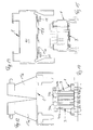
- Fig. 1 shows the cutting of a stamped sheet metal part 1, the has an approximately rectangular base plate region 10, which is limited by bending lines 11, 12, 13, 14. Along the bending line 11, an arm 15 is angled, the one has approximately triangular to trapezoidal outline and one Holding head 16 has. Tabs 17, 18 are on the holding head 16 molded. On the base plate 10 there are extensions 19, 20 provided that beyond the bending line 12 to form Feet 21, 22 are bent. More feet 23, 24 will be by bending longitudinal strips 25, 26 around the bending lines 13, 14 formed.
- Fig. 2 shows a flexprint plate 3, the one Kapton film 30 and a strip-shaped conductor print having a signal path 31 and grounding paths 32 and 33.
- the signal path 31 leads to an antenna contact area 34.
- the tracks 31, 32, 33 each have connection ends 35, 36, 37 with which they connect to corresponding connection areas 45, 46, 47 a circuit board 4 (Fig. 6) are attached.
- the flexprint plate has an approximately T-shaped Outline to accommodate two eyelets 38, 39 adjacent to the Contact field 34 are housed.
- the sheet metal blank 1 receives after bending around the Bending lines 11, 12, 13, 14 and cranking the tabs 17, 18 the form shown in FIGS. 3 to 5.
- This shape forms a frame to support the flexprint plate 3, as from 6 to 8 emerges.
- the feet 21, 22, 23, 24 through holes 41, 42, 43, 44 to the circuit board 4 inserted and anchored in it with conventional means and attached, for example by soldering.
- Fig. 6 shows an antenna 5 which in walls 6 a Housing is fixed and resilient to the abutment or abuts the antenna contact area 34.
- the rear one Antenna tip 51 can be at the level of the contact area 34 Take an angle of 90 ° ⁇ 10 °.
- the Support arm 15 bent at the transition to the head 16 to one Air gap 2 between the stamped sheet metal part 1 or its To create arm 15 and the flexprint plate 3.
- the Signal path 31 is in this way at a certain distance surrounded by metal parts 15, 32 and 33, whereby a Wave resistance of 50 ohms, for example, results as it is desired.
- the ends 35, 36, 37 of the Lanes 31, 32, 33 are with the connection panels 45, 46, 47 of the Circuit board 4 with their respective surfaces connected, which need not be explained in more detail.
- FIG. 9 to 11 show an application of the Antenna connector in the event that the antenna 5 as internal antenna when plugging in an external antenna 7 should be switched off.
- the head of the holding arm 15 points in In this case, a lateral extension 27 by a lateral extension 57 of the flexprint plate is covered on which is an antenna contact field 54, which with the Contact field 34 is connected via a bridge 55. If the external antenna 7 is inserted, it comes on the field 54 to support and bends the holding arm 15 resiliently so that the contact field 34 out of contact with the internal antenna 5 arrives, which is switched off.
- the associated flexprint plate 3 (FIGS. 14, 15) has two signal paths 31a, 31b, each with one Antenna contact field 34a or 34b and two grounding tracks 32a, 32b and 33a, 33b on the respective signal paths accompany.
- the support fields Wear nickel plating with gold layer.
- the areas 35, 36, 37 as well as 45, 46, 47 can be used for superficial reflow soldering to be prepared.
Abstract
Description
Die Erfindung bezieht sich auf einen Antennenverbinder,
insbesondere für Antennen von Handys, nach dem Oberbegriff
des Anspruchs 1.The invention relates to an antenna connector,
especially for antennas of cell phones, according to the generic term
of
Zum Halten von Antennen gibt es recht aufwendige Konstruktionen, die ihren Herstellungspreis kosten.To hold antennas there are quite complex ones Constructions that cost their manufacturing price.
Der Erfindung liegt die Aufgabe zugrunde, einen Antennenverbinder zu schaffen, dessen Herstellungspreis gering ist und der leicht an geforderte unterschiedliche Anschlußbedingungen angepaßt werden kann.The invention has for its object a To create antenna connector, its manufacturing price is small and the easily required different Connection conditions can be adjusted.
Die gestellte Aufgabe wird aufgrund der Merkmale des
Anspruchs 1 gelöst und durch die weiteren Merkmale der
Unteransprüche ausgestaltet und weiterentwickelt.The task is based on the characteristics of the
Im einzelnen ist ein Blechstanzteil vorgesehen, das ein Trägerelement darstellt und für elektrische Abschirmung sorgt. Dieses Blechstanzteil weist abgewinkelte Füße auf, mit denen es auf einer Schaltungsplatte befestigt wird. Außerdem weist das Blechstanzteil einen abgewinkelten Haltearm auf, der zur Stützung einer Flexprintplatte dient, welche die Verbindung zwischen der oder den Antennen und der Schaltungsplatte herstellt. Die Flexprintplatte ist für die elektrischen Eigenschaften des Antennenverbinders verantwortlich und ist leicht austauschbar, so daß man sich den Anforderungen bei der jeweiligen Anwendung leicht anpassen kann. Man braucht beispielsweise nur das Ätzmuster auf der Flexprintplatte zu ändern, was mit geringen Kosten verbunden ist.In particular, a stamped sheet metal part is provided, the one Carrier element represents and for electrical shielding worries. This stamped sheet metal part has angled feet, with which it is attached to a circuit board. Moreover the sheet metal stamped part has an angled holding arm, which serves to support a flexprint plate, which the Connection between the antenna (s) and the Manufactures circuit board. The flexprint plate is for the electrical properties of the antenna connector responsible and is easily interchangeable so that you can the requirements of the respective application easily can adjust. For example, you only need the etching pattern to change on the flexprint plate, what with low cost connected is.
Die Erfindung wird anhand der Zeichnung beschrieben. Dabei zeigt:
- Fig. 1
- ein zugeschnittenes Blechstanzteil in starker Vergrößerung,
- Fig. 2
- eine Flexprintplatte, ebenfalls stark vergrößert,
- Fig. 3
- das zurechtgebogene Blechstanzteil in der Seitenansicht (weniger stark vergrößert),
- Fig. 4
- das zurechtgebogene Blechstanzteil, von vorne gesehen,
- Fig. 5
- das zurechtgebogene Blechstanzteil, von oben gesehen,
- Fig. 6
- einen montierten Antennenverbinder, von der Seite gesehen, gemäß Fig. 3,
- Fig. 7
- den Antennenverbinder, von vorne gesehen,
- Fig. 8
- den Antennenverbinder, von oben gesehen,
- Fig. 9
- einen abgewandelten Antennenverbinder, von der Seite gesehen,
- Fig. 10
- den Antennenverbinder der Fig. 9, von vorne gesehen,
- Fig. 11
- den Antennenverbinder der Fig. 9, von oben gesehen,
- Fig. 12
- ein zurechtgebogenes Blechstanzteil für eine Doppelantenne, von vorne gesehen, und
- Fig. 13
- von oben gesehen
- Fig. 14
- den Antennenverbinder von vorne und
- Fig. 15
- von oben gesehen (verkleinert gemäß Fig. 12, 13).
- Fig. 1
- a cut sheet metal stamping in high magnification,
- Fig. 2
- a flexprint plate, also greatly enlarged,
- Fig. 3
- the bent sheet metal stamping in side view (less enlarged),
- Fig. 4
- the bent sheet metal stamping, seen from the front,
- Fig. 5
- the bent sheet metal stamped part, seen from above,
- Fig. 6
- an assembled antenna connector, seen from the side, as shown in FIG. 3,
- Fig. 7
- the antenna connector, seen from the front,
- Fig. 8
- the antenna connector, seen from above,
- Fig. 9
- a modified antenna connector, seen from the side,
- Fig. 10
- 9, seen from the front,
- Fig. 11
- 9, seen from above,
- Fig. 12
- a bent sheet metal stamping for a double antenna, seen from the front, and
- Fig. 13
- seen from above
- Fig. 14
- the antenna connector from the front and
- Fig. 15
- seen from above (reduced according to Fig. 12, 13).
Fig. 1 zeigt den Zuschnitt eines Blechstanzteils 1, das
einen etwa rechteckförmigen Basisplattenbereich 10 aufweist,
der durch Biegelinien 11, 12, 13, 14 begrenzt wird. Entlang
der Biegelinie 11 wird ein Haltearm 15 abgewinkelt, der einen
etwa dreieck- bis trapezförmigen Umriß aufweist und einen
Haltekopf 16 besitzt. Am Haltekopf 16 sind Laschen 17, 18
angeformt. An der Basisplatte 10 sind Fortsätze 19, 20
vorgesehen, die jenseits der Biegelinie 12 zur Bildung von
Füßen 21, 22 abgebogen werden. Weitere Füße 23, 24 werden
durch Abbiegen von Längsstreifen 25, 26 um die Biegelinien
13, 14 gebildet.Fig. 1 shows the cutting of a stamped
Fig. 2 zeigt eine Flexprintplatte 3, die eine
Kaptonfolie 30 sowie einen streifenförmigen Leiteraufdruck
mit einer Signalbahn 31 und Erdungsbahnen 32 und 33 aufweist.
Die Signalbahn 31 führt zu einem Antennenkontaktbereich 34.
Die Bahnen 31, 32, 33 weisen jeweils Anschlußenden 35, 36, 37
auf, mit denen sie auf entsprechende Anschlußbereiche 45, 46,
47 einer Schaltungsplatte 4 (Fig. 6) befestigt sind. Wie
dargestellt, weist die Flexprintplatte einen etwa T-förmigen
Umriß auf, um zwei Ösen 38, 39 unterzubringen, die neben dem
Kontaktfeld 34 untergebracht sind.Fig. 2 shows a
Der Blechzuschnitt 1 erhält nach Biegen um die
Biegelinien 11, 12, 13, 14 sowie Abkröpfen der Laschen 17, 18
die aus den Fig. 3 bis 5 ersichtliche Form. Diese Form bildet
einen Rahmen, um die Flexprintplatte 3 zu stützen, wie aus
den Fig. 6 bis 8 hervorgeht. Dabei werden die Füße 21, 22,
23, 24 durch Bohrungen 41, 42, 43, 44 an die Schaltungsplatte
4 gesteckt und darin mit konventionellen Mitteln verankert
und befestigt, beispielsweise durch Löten.The
Es ist natürlich auch möglich, die Füße 21 bis 24 durch
weiteres Abbiegen zur Oberflächenmontage auf der
Schaltungsplatte 4 auszubilden, wobei dann an den Stellen der
Bohrungen 41 bis 44 Anschlußflecken geeignet vorbereitet
sind.It is of course also possible to put
Fig. 6 zeigt eine Antenne 5, die in Wänden 6 eines
Gehäuses festgemacht ist und federnd an dem Widerlager bzw.
am Antennenkontaktbereich 34 anliegt. Die hintere
Antennenspitze 51 kann zur Ebene des Kontaktbereichs 34 einen
Winkel von 90° ± 10° einnehmen. Wie ersichtlich, ist der
Haltearm 15 am Übergang zum Kopf 16 abgekröpft, um einen
Luftspalt 2 zwischen dem Blechstanzteil 1 bzw. dessen
Haltearm 15 und der Flexprintplatte 3 zu schaffen. Die
Signalbahn 31 wird auf diese Weise in bestimmter Entfernung
von Metallteilen 15, 32 und 33 umgeben, wodurch sich ein
Wellenwiderstand von beispielsweise 50 Ohm ergibt, wie es
erwünscht ist. Gegebenenfalls sind an den Wänden 6
Metallisierungen angebracht, um die Abschirmung und den
Wellenwiderstand zu beeinflussen. Die Enden 35, 36, 37 der
Bahnen 31, 32, 33 sind mit den Anschlußfeldern 45, 46, 47 der
Schaltungsplatte 4 mit ihren jeweiligen Oberflächen
verbunden, was nicht näher erläutert werden muß.Fig. 6 shows an
Fig. 9 bis 11 zeigen eine Anwendung des
Antennenverbinders für den Fall, daß die Antenne 5 als
interne Antenne beim Einstecken einer externen Antenne 7
abgeschaltet werden soll. Der Kopf des Haltearms 15 weist in
diesem Fall einen seitlichen Fortsatz 27 auf, der von einem
seitlichen Fortsatz 57 der Flexprintplatte bedeckt ist, auf
der sich ein Antennenkontaktfeld 54 befindet, das mit dem
Kontaktfeld 34 über eine Brücke 55 verbunden ist. Wenn die
externe Antenne 7 eingeführt wird, kommt sie auf dem Feld 54
zur Auflage und biegt den Haltearm 15 federnd zurück, so daß
das Kontaktfeld 34 außer Anlage mit der internen Antenne 5
gelangt, die dadurch abgeschaltet wird.9 to 11 show an application of the
Antenna connector in the event that the
Die Fig. 12 und 13 zeigen ein gebogenes Blechstanzteil
mit zwei unabhängig federnden Widerlagern 15a, 15b für eine
Doppelantenne. Die zugehörige Flexprintplatte 3 (Fig. 14, 15)
weist zwei Signalbahnen 31a, 31b mit jeweils einem
Antennenkontaktfeld 34a bzw. 34b und zwei Erdungsbahnen 32a,
32b bzw. 33a, 33b auf, die die jeweiligen Signalbahnen
begleiten.12 and 13 show a bent sheet metal stamped part
with two independently resilient abutments 15a, 15b for one
Dual antenna. The associated flexprint plate 3 (FIGS. 14, 15)
has two signal paths 31a, 31b, each with one
Es versteht sich, daß die beschriebene Anheftung der Flexprintplatte an dem Blechstanzteil nicht über eine Laschen-Ösen-Verbindung erfolgen muß, daß vielmehr auch andere Verbindungsmittel möglich sind, beispielsweise Anheftung mit Druckknöpfen, Klettverschlußausbildung oder dergleichen. Auch das Aufkleben mit Klebeschicht oder mit doppelseitigem Klebeband ist möglich.It is understood that the attachment described Flexprint plate on the sheet metal stamped part does not have a Tab-eye connection must be done that much more other connecting means are possible, for example Attachment with snaps, Velcro training or the like. Also stick on with adhesive layer or with double-sided adhesive tape is possible.
Im Bereich der Kontaktfelder können die Auflagefelder
Vernickelung mit Goldschicht tragen. Die Bereiche 35, 36, 37
sowie 45, 46, 47 können für das oberflächliche Reflow-Löten
vorbereitet sein.In the area of the contact fields, the support fields
Wear nickel plating with gold layer. The
Von besonderem Vorteil ist, daß die Teile des Antennenverbinders ausreichend große ebene Flächen aufweisen, an denen Vakuum angelegt werden kann, um diese Teile mit Vakuumgreifern zu handhaben. Dadurch wird die automatische Montage erleichtert.It is particularly advantageous that the parts of the Have sufficiently large flat surfaces, where vacuum can be applied to these parts To handle vacuum grippers. This will make the automatic Assembly easier.
Claims (10)
dadurch gekennzeichnet, daß das Blechstanzteil (1) einen zur Schaltungsplatte (4) parallel verlaufenden, rechteckförmigen Basisplattenteil (10) mit vier Seiten aufweist, zu dessen erster Seite der Haltearm (15) abgewinkelt ist und eine Antennenkontaktebene bestimmt, daß von der zweiten, gegenüberliegenden Seite des Basisplattenteils (10) erste und zweite abgewinkelte Füße (21, 22) entgegen der Erstreckungsrichtung des Haltearmes (15) ausgehen und daß von der dritten und vierten Seite des Basisplattenteils (10) jeweils dritte und vierte abgewinkelte Füße (23, 24) über Verbindungsstreifen (25, 26) angeschlossen sind, die von den ersten und zweiten Füßen (21, 22) wegstreben, um eine Vierpunkt-Befestigung des Blechstanzteils (1) an der Schaltungsplatte (4) mit breiter Basis zu ermöglichen.Antenna connector according to claim 1,
characterized in that the sheet-metal stamped part (1) has a rectangular base plate part (10) with four sides running parallel to the circuit board (4), the holding arm (15) being angled to the first side and an antenna contact plane determining that of the second, opposite one Side of the base plate part (10) go out first and second angled feet (21, 22) against the direction of extension of the holding arm (15) and that from the third and fourth side of the base plate part (10) respectively third and fourth angled feet (23, 24) Connecting strips (25, 26) are connected, which strive away from the first and second feet (21, 22) in order to enable a four-point fastening of the sheet metal stamped part (1) to the circuit board (4) with a wide base.
dadurch gekennzeichnet, daß der Haltearm (15) trapezförmig, mit einem Haltekopf (16), ausgebildet ist.Antenna connector according to claim 1 or 2,
characterized in that the holding arm (15) is trapezoidal, with a holding head (16).
dadurch gekennzeichnet, daß der Haltekopf (16) zwei Laschen (17, 18) zum Durchstecken durch Öffnungen (38, 39) in der Flexprintplatte (3) aufweist.Antenna connector according to claim 3,
characterized in that the holding head (16) has two tabs (17, 18) for insertion through openings (38, 39) in the flexprint plate (3).
dadurch gekennzeichnet, daß der Haltekopf (16) gegenüber dem Rest des Haltearms (15) abgekröpft ist, um eine Luftschicht (2) zwischen Flexprintplatte (3) und Blechstanzteil (1) zu bilden.Antenna connector according to claim 3 or 4,
characterized in that the holding head (16) is bent relative to the rest of the holding arm (15) in order to form an air layer (2) between the flexprint plate (3) and the stamped sheet metal part (1).
dadurch gekennzeichnet, daß die Flexprintplatte (3) eine Kaptonfolie und eine Leiterschicht zur Bildung der Signalbahn und der Erdungsbahnen aufweist.Antenna connector according to one of claims 1 to 5,
characterized in that the flexprint plate (3) has a Kapton film and a conductor layer to form the signal path and the ground paths.
dadurch gekennzeichnet, daß die Flexprintplatte (3) eine doppelseitige Beschichtung trägt. Antenna connector according to one of claims 1 to 6,
characterized in that the flexprint plate (3) has a double-sided coating.
dadurch gekennzeichnet, daß der Haltekopf (16) einen seitlichen Fortsatz (27) äufweist, der gegenüber der Ebene seines Haltearms (15) leicht abgewinkelt ist, und daß die Flexprintplatte (3) in Überdeckung dieses seitlichen Fortsatzes (27) einen weiteren Antennenkontaktbereich (54) aufweist, der beim Einstecken einer weiteren (externen) Antenne (7) wirksam wird und den ersten Antennenkontaktbereich (34) von der ersten (internen) Antenne (5) abhebt.Antenna connector according to one of claims 3 to 7,
characterized in that the holding head (16) has a lateral extension (27) which is slightly angled relative to the plane of its holding arm (15), and in that the flexprint plate (3) overlaps this lateral extension (27) a further antenna contact area (54 ), which takes effect when a further (external) antenna (7) is inserted and lifts the first antenna contact area (34) from the first (internal) antenna (5).
dadurch gekennzeichnet, daß der Haltearm (15) zwei unabhängig federnde Widerlager (15a, 15b) zur Anlage zweier Antennen bzw. einer Doppelantenne enthält.Antenna connector according to one of claims 1 to 8,
characterized in that the holding arm (15) contains two independently resilient abutments (15a, 15b) for the installation of two antennas or a double antenna.
dadurch gekennzeichnet, daß die Flexprintplatte (3) zur Versorgung einer Doppelantenne zwei getrennte Signalbahnen (31a, 31b) mit zugehörigen Antennenkontaktbereichen (34a, 34b) und vier streifenförmige Erdungsbahnen (32a, 32b; 33a, 33b) aufweist.Antenna connector according to one of claims 1 to 9,
characterized in that the flexprint plate (3) has two separate signal paths (31a, 31b) with associated antenna contact areas (34a, 34b) and four strip-shaped grounding paths (32a, 32b; 33a, 33b) for supplying a double antenna.
Priority Applications (1)
| Application Number | Priority Date | Filing Date | Title |
|---|---|---|---|
| EP99111164A EP1061604A1 (en) | 1999-06-08 | 1999-06-08 | Antenna connector |
Applications Claiming Priority (1)
| Application Number | Priority Date | Filing Date | Title |
|---|---|---|---|
| EP99111164A EP1061604A1 (en) | 1999-06-08 | 1999-06-08 | Antenna connector |
Publications (1)
| Publication Number | Publication Date |
|---|---|
| EP1061604A1 true EP1061604A1 (en) | 2000-12-20 |
Family
ID=8238321
Family Applications (1)
| Application Number | Title | Priority Date | Filing Date |
|---|---|---|---|
| EP99111164A Withdrawn EP1061604A1 (en) | 1999-06-08 | 1999-06-08 | Antenna connector |
Country Status (1)
| Country | Link |
|---|---|
| EP (1) | EP1061604A1 (en) |
Cited By (1)
| Publication number | Priority date | Publication date | Assignee | Title |
|---|---|---|---|---|
| CN110281709A (en) * | 2019-06-12 | 2019-09-27 | 深圳市永奥图电子有限公司 | A kind of external tire-pressure monitoring device |
Citations (5)
| Publication number | Priority date | Publication date | Assignee | Title |
|---|---|---|---|---|
| US4636016A (en) * | 1985-08-30 | 1987-01-13 | Motorola, Inc. | Accessory connector |
| EP0555949A1 (en) * | 1992-02-14 | 1993-08-18 | Robert Karst GmbH & Co. KG. | Fastening device for mobile apparatus connector |
| EP0773633A2 (en) * | 1995-11-08 | 1997-05-14 | Nokia Mobile Phones Ltd. | Housing for portable radio |
| US5835071A (en) * | 1996-09-25 | 1998-11-10 | Ericsson, Inc. | Shielded antenna connector |
| US5907817A (en) * | 1996-12-24 | 1999-05-25 | Ericsson Inc. | Radiotelephones with coplanar antenna connectors and related assembly methods |
-
1999
- 1999-06-08 EP EP99111164A patent/EP1061604A1/en not_active Withdrawn
Patent Citations (5)
| Publication number | Priority date | Publication date | Assignee | Title |
|---|---|---|---|---|
| US4636016A (en) * | 1985-08-30 | 1987-01-13 | Motorola, Inc. | Accessory connector |
| EP0555949A1 (en) * | 1992-02-14 | 1993-08-18 | Robert Karst GmbH & Co. KG. | Fastening device for mobile apparatus connector |
| EP0773633A2 (en) * | 1995-11-08 | 1997-05-14 | Nokia Mobile Phones Ltd. | Housing for portable radio |
| US5835071A (en) * | 1996-09-25 | 1998-11-10 | Ericsson, Inc. | Shielded antenna connector |
| US5907817A (en) * | 1996-12-24 | 1999-05-25 | Ericsson Inc. | Radiotelephones with coplanar antenna connectors and related assembly methods |
Cited By (2)
| Publication number | Priority date | Publication date | Assignee | Title |
|---|---|---|---|---|
| CN110281709A (en) * | 2019-06-12 | 2019-09-27 | 深圳市永奥图电子有限公司 | A kind of external tire-pressure monitoring device |
| CN110281709B (en) * | 2019-06-12 | 2024-01-16 | 深圳市永奥图电子有限公司 | External tire pressure monitor |
Similar Documents
| Publication | Publication Date | Title |
|---|---|---|
| DE69634005T2 (en) | CONNECTORS WITH INTEGRATED PCB ASSEMBLY | |
| DE4310288B4 (en) | Surface mountable resistor | |
| DE3544838C2 (en) | ||
| DE4217205C2 (en) | Connectors | |
| EP2728982B1 (en) | Circuit board module for a control device, control device for a motor vehicle and signal processing assembly | |
| EP2569827B1 (en) | Supporting rail bus system | |
| DE3535923C2 (en) | ||
| DE112006002517T5 (en) | Chip Resistor | |
| DE112006002516T5 (en) | Chip Widertand | |
| DE2800006A1 (en) | UNIVERSALLY PROGRAMMABLE SHORT CIRCUIT PLUG FOR A SOCKET OF AN INTEGRATED CIRCUIT | |
| DE19820414A1 (en) | Contacting device | |
| DE102014216932A1 (en) | Printed circuit board for mounting a bridging module and printed circuit board assembly | |
| DE60310303T2 (en) | PCB edge connector and card | |
| EP1571735B1 (en) | Electrotechnical component | |
| DE10153726A1 (en) | Flexible circuit board and connection of the structure thereof | |
| DE69730174T2 (en) | Mounting structure for mounting an electrical module on a plate | |
| DE3011744C3 (en) | Multi-core connector | |
| DE3545527A1 (en) | FLEXIBLE ELECTRICAL CONNECTING DEVICE AND METHOD FOR THEIR PRODUCTION | |
| EP0402739B1 (en) | Device for electrical connecting of sliding electrical assemblies | |
| EP1061604A1 (en) | Antenna connector | |
| EP0955702A1 (en) | Printed circuit board connecting device | |
| EP0384022A1 (en) | High-voltage electrode arrangement | |
| EP0076292A1 (en) | Electric contact, particularly for printed circuits of small electric appliances. | |
| DE112017004704T5 (en) | Current measuring device | |
| DE60201537T2 (en) | ELECTRICAL CONNECTION ARRANGEMENT FOR ELECTRONIC COMPONENTS |
Legal Events
| Date | Code | Title | Description |
|---|---|---|---|
| PUAI | Public reference made under article 153(3) epc to a published international application that has entered the european phase |
Free format text: ORIGINAL CODE: 0009012 |
|
| AK | Designated contracting states |
Kind code of ref document: A1 Designated state(s): DE FR GB IT |
|
| AX | Request for extension of the european patent |
Free format text: AL;LT;LV;MK;RO;SI |
|
| 17P | Request for examination filed |
Effective date: 20010612 |
|
| AKX | Designation fees paid |
Free format text: DE FR GB IT |
|
| STAA | Information on the status of an ep patent application or granted ep patent |
Free format text: STATUS: THE APPLICATION IS DEEMED TO BE WITHDRAWN |
|
| 18D | Application deemed to be withdrawn |
Effective date: 20021231 |