EP1061387A2 - System comprising plastic optical fiber - Google Patents
System comprising plastic optical fiber Download PDFInfo
- Publication number
- EP1061387A2 EP1061387A2 EP00304770A EP00304770A EP1061387A2 EP 1061387 A2 EP1061387 A2 EP 1061387A2 EP 00304770 A EP00304770 A EP 00304770A EP 00304770 A EP00304770 A EP 00304770A EP 1061387 A2 EP1061387 A2 EP 1061387A2
- Authority
- EP
- European Patent Office
- Prior art keywords
- fiber
- length
- plastic optical
- optical fiber
- strain
- Prior art date
- Legal status (The legal status is an assumption and is not a legal conclusion. Google has not performed a legal analysis and makes no representation as to the accuracy of the status listed.)
- Granted
Links
- 239000013308 plastic optical fiber Substances 0.000 title claims abstract description 50
- 239000000835 fiber Substances 0.000 claims abstract description 104
- 238000000034 method Methods 0.000 claims abstract description 38
- 230000006835 compression Effects 0.000 claims abstract description 21
- 238000007906 compression Methods 0.000 claims abstract description 21
- 230000001939 inductive effect Effects 0.000 claims description 6
- 238000005498 polishing Methods 0.000 abstract description 7
- 230000001976 improved effect Effects 0.000 abstract description 5
- 230000003287 optical effect Effects 0.000 abstract description 4
- 239000000463 material Substances 0.000 description 7
- 230000033001 locomotion Effects 0.000 description 6
- 239000013307 optical fiber Substances 0.000 description 6
- 239000011521 glass Substances 0.000 description 5
- 230000002787 reinforcement Effects 0.000 description 4
- 229920003229 poly(methyl methacrylate) Polymers 0.000 description 3
- 239000004926 polymethyl methacrylate Substances 0.000 description 3
- 230000005540 biological transmission Effects 0.000 description 2
- -1 poly(perfluorobutenyl vinyl ether) Polymers 0.000 description 2
- 230000003014 reinforcing effect Effects 0.000 description 2
- RYGMFSIKBFXOCR-UHFFFAOYSA-N Copper Chemical compound [Cu] RYGMFSIKBFXOCR-UHFFFAOYSA-N 0.000 description 1
- 244000208734 Pisonia aculeata Species 0.000 description 1
- 238000013459 approach Methods 0.000 description 1
- 238000003776 cleavage reaction Methods 0.000 description 1
- 238000004891 communication Methods 0.000 description 1
- 238000007796 conventional method Methods 0.000 description 1
- 230000003247 decreasing effect Effects 0.000 description 1
- 230000007547 defect Effects 0.000 description 1
- 238000013461 design Methods 0.000 description 1
- 230000001627 detrimental effect Effects 0.000 description 1
- 239000006185 dispersion Substances 0.000 description 1
- 230000000694 effects Effects 0.000 description 1
- 230000000977 initiatory effect Effects 0.000 description 1
- 230000013011 mating Effects 0.000 description 1
- 229920003023 plastic Polymers 0.000 description 1
- 239000004033 plastic Substances 0.000 description 1
- 238000012545 processing Methods 0.000 description 1
- 230000001902 propagating effect Effects 0.000 description 1
- 230000007017 scission Effects 0.000 description 1
Images
Classifications
-
- G—PHYSICS
- G02—OPTICS
- G02B—OPTICAL ELEMENTS, SYSTEMS OR APPARATUS
- G02B6/00—Light guides; Structural details of arrangements comprising light guides and other optical elements, e.g. couplings
- G02B6/24—Coupling light guides
- G02B6/25—Preparing the ends of light guides for coupling, e.g. cutting
Definitions
- the invention relates to plastic optical fiber.
- Glass optical fiber has become a significant transmission medium in recent years, particularly for long distance transmission applications. Such optical fiber has not found significant usage, however, in smaller scale applications, such as distribution of fiber to the desk in local area networks.
- glass optical fiber has not been as cost effective as, for example, copper wire, and also requires extremely precise fiber connections, e.g., end face polishing, alignment, and index-matching material.
- plastic optical fiber which offers many of the benefits of glass optical fiber, but is expected to offer more cost effective systems. POF also offers some unique characteristics, including a larger core and desirable dispersion properties, which are expected to make connection and splicing easier.
- the invention relates to POF processes and systems and involves improved termination techniques that make dry, non-polished connection more acceptable.
- the techniques provide good physical characteristics, i.e., smoothness, at the termination end face, thereby providing lower loss connections than conventionally obtained. For example, losses less than 1 dB have been obtained without polishing or index-matching material, e.g., for CYTOP® fiber having a polymethylmethacrylate reinforcement (CYTOP® is poly(perfluorobutenyl vinyl ether), and is available commercially from Asahi Glass Co., Japan).
- POF is cut while the fiber is under axial compression, and the usable piece (or pieces) is typically removed prior to pulling back the blade or knife.
- the resulting termination exhibits a smooth surface that promotes low loss in a dry, non-polished connection.
- the POF is cleaved. Specifically, the fiber is notched and then pulled at a relatively high strain rate to induce fracture. The rate is such that the strain remains in the elastic region up to and during fracture, i.e., the fiber exhibits brittle, as opposed to ductile, behavior during the strain and fracture. The brittle behavior is necessary for a smooth termination surface that similarly promotes low loss in a dry, non-polished connection.
- non-polished POF terminations having improved physical and optical characteristics, e.g., smoothness, and thereby provide lower losses when preparing dry, non-polished connections.
- Non-polished indicates that polishing of the terminated end faces is not performed prior to connection. Dry indicates that index-matching material is not used when making the connection.
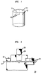
- branching cracks 12 run into the fiber 10 from the end face. The branching cracks 12 are believed to contribute to the undesirably high losses exhibited by POF connections. According to the invention, however, it is possible to terminate POF such that substantially no branching cracks are induced.
- POF is cut while the fiber is under axial compression, i.e., a compressive axial strain is applied prior to cutting.
- a compressive strain of approximately 1% is sufficient to provide a relatively smooth termination surface substantially free of branching cracks, although lower levels of strain are also suitable in some cases.
- the resulting usable piece (or pieces) is typically removed prior to pulling back the blade or knife, to avoid damaging the surface during such pull-back.
- a single cutting edge is used to terminate the fiber in a direction normal to the fiber axis.
- a conventional razor blade e.g., as used for shaving, is generally suitable. Such blades tend to have a cutting edge with a radius of curvature substantially less than 10 ⁇ m, more typically substantially less than 1 ⁇ m.
- a variety of tools are suitable for providing such compressive-fiber cutting.
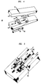
- a fiber 21 is threaded through the tool 20 and clamped into a fixed clamp 22 at one end and a floating clamp 23 at the other end.
- the floating clamp 23 is pushed toward the fixed clamp 22, providing compression, and a blade 24 located in a housing 25 is pushed through the fiber 21.
- the cut fiber 21 is then unclamped and removed, typically before pulling back the blade 24.
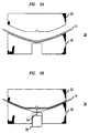
- the cutting tool 30 shown in Figs. 3A and 3B reflects a more general technique. Specifically, the tool 30 contains lower and upper portions 32, 33.
- the lower portion 32 defines a curvature onto which is placed a plastic optical fiber 31, which conforms to the curvature, as shown in Fig. 3A.
- the lower portion 32 and upper portion 33 are then brought together until the fiber 31 becomes clamped.
- a blade 34 located in a housing 35 is then inserted through an opening in the lower portion 32. As shown in Fig. 3B, the blade 34 contacts the curved fiber 21, pushes the fiber 21 against the upper portion 33, thereby decreasing the fiber's 21 length and inducing compression in the fiber 21.
- the upper portion 33 is generally normal to the blade at the area where the fiber 21 contacts the upper portion 33.). With the fiber under compression, the blade then cuts into the fiber 21 to effect termination. The clamp is then opened, and the fiber is removed.
- the technique reflected in Figs. 3A and 3B is useful with a variety of tools. In general, the technique involves orienting the clamped fiber such that the initial force of the blade induces the compression, and the continued force then cuts the fiber.
- FIG. 4 A more detailed view of one embodiment of a tool of this type is shown in Fig. 4.
- the tool 40 contains an upper housing 43 and a lower housing 42, connected by a hinged mechanism 44 that includes a wire spring 45 (notch 51 in upper housing 43 is provided for accepting the upper portion (not shown) of the spring 45).
- the lower housing 42 contains a curved cavity 46, the cavity 46 including a similarly curved guide 47 for placement of a fiber therein.
- the cavity 46 further contains an opening 48 for the blade 49, which is located in a blade housing 50.
- the tool 40 operates as explained in regards to Figs. 3A and 3B.
- the tool 60 contains a first plunger 61 having a first fiber guide area 62 and a second plunger 63 having a second fiber guide area 64.
- the tool 60 also contains a blade guide 65.
- the first and second plungers 61, 63 are moved in the direction a and a', as shown in Fig. 5.
- the first and second guide areas 62, 64 open to freely accept a fiber 66.
- the first plunger 61 is moved in direction b, which causes the first guide area 62 to close and thereby firmly fix the fiber 66.
- the movement in direction b of the first plunger 61 also induces movement of the closed first guide area 62 in direction b by compression of a first spring 67.
- This movement of the first guide area 62 induces a curvature and length increase in the portion of fiber 66 located between the first and second plungers, as shown in Fig. 5.
- the second plunger 63 is similarly moved in direction b', which closes the second fiber guide area 64, fixing the fiber 66.
- the movement of the second plunger 63 in direction b' also moves the fixed fiber 66 in direction b', by compression of a second spring 68.
- This fixing of the fiber 66 in the second guide area 64 and subsequent movement of the fiber in the b' direction induces the desired axial compression of the fiber 66 in the area between the first and second guide areas 62, 64.
- This compressed portion of the fiber 66 is then cut with a blade (not shown) inserted into the blade guide 65.
- the POF is cleaved. Specifically, the fiber is notched and then pulled at a relatively high strain rate to induce fracture.
- the rate is such that the strain remains in the elastic region of a stress-strain curve, i.e., the fiber exhibits brittle, as opposed to ductile, behavior during the strain, and exhibits very little plastic deformation, particularly in the optically active areas of the fiber.
- the brittle behavior provides a smooth termination surface, as opposed to a rough, plastically-deformed surface.
- the radius of curvature of the notch is less than 10 ⁇ m, advantageously less than 1 ⁇ m, and more advantageously less than 0.1 ⁇ m.
- a strain rate of at least 1 sec -1 is typically sufficient to attain a smooth, brittle fracture surface for a variety of notch sizes.
- lower strain rates e.g., 0.1 sec -1 , or even 0.01 sec -1 in the case of very small notch radii of curvature, would be suitable.
- Cleavage is generally performed simply by notching a fiber with a blade, e.g., a razor blade, by a guillotine or sawing motion, fixing one end of the fiber, and pulling the other end to induce fracture. It is also possible to secure and pull both ends in opposite directions to induce fracture.
- the notch is typically made to a depth of about 10 to about 30% of the diameter of the plastic optical fiber, depending on the particular fiber structure. For example, for POF having a reinforcing layer, it is possible for the notch to completely or partially penetrate the reinforcing layer. Control samples are easily used to determine an appropriate notch depth for a particular fiber.
- plastic optical fiber is capable of being terminated such that relatively smooth end faces result.
- the termination techniques are easier than conventional techniques used for glass optical fiber.
- connections between the resultant end faces, without polishing and without index-matching material are able to exhibit a relatively low loss of less than 1 dB.
- the termination techniques of the invention therefore ease the overall design and set-up of various systems that use POF, e.g., local area networks, campus systems, and consumer-installed home systems, thereby reducing cost.
- a 2.5 m length of a plastic optical fiber with a 235 ⁇ m diameter CYTOP® center section (including both doped and undoped material) and a 500 ⁇ m diameter outer polymethylmethacrylate reinforcement was cut in two with a knife. Then, using a tool such as shown in Fig. 2, each fiber was axially compressed near the cut end, under an approximately 1% strain, and a conventional double-edged razor blade was pressed completely through each fiber, removing approximately 1 ⁇ 2 inch from each fiber's end. These two terminated ends were mated in an alignment sleeve, with the other two ends connected to a 850 nm laser source and a large area photodetector, respectively. The amount of light transmitted was measured and compared to the amount transmitted through the original uncut fiber length. The loss resulting from the connection was about 0.7dB.
- a length of plastic optical fiber was obtained.
- the fiber had a 250 ⁇ m CYTOP® center section (including both doped and undoped material) with a PMMA reinforcement layer having an outer diameter of 500 microns.
- a 0.6 m length of experimental POF was obtained by making a small notch perpendicular to the fiber axis.
- the tip of the blade used to produce the notch had a radius of curvature less than 0.1 micron, and the notch depth was approximately 100 microns.
- the notched fiber was placed in an Instron controlled-strain apparatus. In this apparatus, two clamps separated by a gauge length of 0.75" applied a longitudinal strain on the fiber. The notch was positioned halfway between the clamps, and the fiber was strained at a rate of 50 inches/minute until breaking at the notch point.
- the uncleaved end face of one cleaved fiber length was polished.
- Another 0.6m length (length B) of the fiber was obtained by polishing both the cleaved and uncleaved end faces.
- Fiber length B was coupled to an 850 nm laser source on one end, and the power output at the other end was measured with a large area photodetector.
- the cleaved end face of fiber length A was then mated with the output end of fiber length B in an alignment sleeve.
- the power output from the polished end face of fiber A with the large area photodetector was then monitored.
- the additional loss added to the system by this mating of a cleaved and polished connection was 0.9 dB.
Landscapes
- Physics & Mathematics (AREA)
- General Physics & Mathematics (AREA)
- Optics & Photonics (AREA)
- Light Guides In General And Applications Therefor (AREA)
- Mechanical Coupling Of Light Guides (AREA)
- Optical Fibers, Optical Fiber Cores, And Optical Fiber Bundles (AREA)
Abstract
Description
Claims (12)
- A process for fabricating an article comprising plastic optical fiber, comprising the steps of:providing a length of plastic optical fiber;inducing axial compression on the length of fiber such that a compressive strain of at least 1% is induced on the length of fiber; andcutting the length of fiber while the fiber is under compression.
- The process of claim 1, further comprising the steps of:providing a second length of plastic optical fiber;inducing axial compression on the second length of fiber such that a compressive strain of at least 1% is induced on the length of fiber;cutting the second length of fiber while the fiber is under compression; andconnecting together end faces of the first and second lengths of fiber resulting from the cutting, by a dry, non-polished technique, wherein the connection exhibits a loss less than 1 dB.
- A process for fabricating an article comprising plastic optical fiber, comprising the steps of:placing a plastic optical fiber into a support apparatus, such that the fiber assumes a curvature;securing end portions of the fiber;pressing a blade onto the fiber between the secured end portions, such that the force of the blade reduces the curvature and the length of the fiber between the secured end portions, the reduced length inducing an axial compressive strain; andwithout removing the compressive strain, pressing the blade into the fiber to cut the fiber.
- A process for fabricating an article comprising plastic optical fiber, comprising the steps of:placing a plastic optical fiber into a support apparatus;securing a first end portion of the fiber;securing a second end portion of the fiber such that the step of securing the second end portion induces axial compression on a length of the fiber between the first and second end portions; andcutting the length of the fiber at a location between the first and the second end portions while the length is under the axial compression.
- A tool for terminating plastic optical fiber, comprising;a first support structure comprising a curved cavity for inducing a curvature in a length of fiber placed in the cavity, the cavity comprising an opening for accepting a cutting blade;a second structure capable of being brought against the first structure to secure end portions of the length of fiber;a blade housing attached to the first support structure, the blade housing comprising a cutting blade capable of being directed into the cavity opening to contact the length of fiber between the secured end portions.
- A process for fabricating an article comprising plastic optical fiber, comprising the steps of:providing a length of plastic optical fiber;notching the length of fiber; andpulling at least one end portion of the length to fracture the fiber, wherein the pulling is performed at a strain rate sufficient to keep the strain in an elastic region during the fracture.
- The process of claim 6, wherein a first end portion is secured and a second end portion is pulled in a direction opposite the first end portion to fracture the fiber.
- The process of claim 6, wherein first and second end portions are pulled in opposite directions to fracture the fiber.
- The process of claim 6, wherein the notch is provided by cutting the fiber to a depth of about 10 to about 30% of the fiber diameter.
- The process of claim 6, wherein the radius of curvature is less than 1µm, or is less than 0.1 µm.
- The process of claim 6, wherein the strain rate is at least 1 sec-1, or is at least 0.1 sec-1.
- The process of claim 6, further comprising the steps of:providing a second length of plastic optical fiber;notching the second length of fiber;pulling at least one end portion of the length to fracture the fiber, wherein the pulling is performed at a strain rate sufficient to keep the strain in an elastic region during the fracture; andconnecting together end faces of the first and second lengths of fiber resulting from the fracture by a dry, non-polished technique, such that the connection exhibits a loss less than 1dB.
Applications Claiming Priority (4)
| Application Number | Priority Date | Filing Date | Title |
|---|---|---|---|
| US13961499P | 1999-06-17 | 1999-06-17 | |
| US139614P | 1999-06-17 | ||
| US349191 | 1999-07-07 | ||
| US09/349,191 US6636672B1 (en) | 1999-07-07 | 1999-07-07 | System comprising plastic optical fiber |
Publications (3)
| Publication Number | Publication Date |
|---|---|
| EP1061387A2 true EP1061387A2 (en) | 2000-12-20 |
| EP1061387A3 EP1061387A3 (en) | 2004-02-25 |
| EP1061387B1 EP1061387B1 (en) | 2008-01-09 |
Family
ID=26837400
Family Applications (1)
| Application Number | Title | Priority Date | Filing Date |
|---|---|---|---|
| EP20000304770 Expired - Lifetime EP1061387B1 (en) | 1999-06-17 | 2000-06-06 | Process for a system comprising a plastic optical fibre |
Country Status (6)
| Country | Link |
|---|---|
| EP (1) | EP1061387B1 (en) |
| JP (1) | JP3805175B2 (en) |
| AU (1) | AU4083100A (en) |
| BR (1) | BR0002597A (en) |
| CA (1) | CA2310720A1 (en) |
| DE (1) | DE60037700T2 (en) |
Cited By (3)
| Publication number | Priority date | Publication date | Assignee | Title |
|---|---|---|---|---|
| DE10043173A1 (en) * | 2000-09-01 | 2002-03-28 | Fci Automotive Deutschland Gmb | Device for cutting polymer optical fiber optical fibers (POF-LWL) |
| EP1273939A3 (en) * | 2001-07-04 | 2004-09-29 | Wezag GmbH Werkzeugfabrik | Method and pliers for cutting of amorph optical fiber cables |
| WO2009105770A1 (en) * | 2008-02-22 | 2009-08-27 | Molex Incorporated | Optical fiber tool |
Families Citing this family (2)
| Publication number | Priority date | Publication date | Assignee | Title |
|---|---|---|---|---|
| EP2212730B1 (en) * | 2007-10-19 | 2013-12-11 | 3M Innovative Properties Company | Bladeless optical fiber cleaver and method |
| EP4239382A1 (en) * | 2020-11-02 | 2023-09-06 | Nitto Denko Corporation | Method for constructing light transmission system, and on-site construction set |
Family Cites Families (15)
| Publication number | Priority date | Publication date | Assignee | Title |
|---|---|---|---|---|
| JPS52137352A (en) * | 1976-05-13 | 1977-11-16 | Sumitomo Electric Ind Ltd | Cutting method of optical fibers |
| FR2487812B1 (en) * | 1980-07-31 | 1985-06-07 | Socapex | OPTICAL FIBER COLLECTIVE BREAKDOWN TOOLS |
| FR2492363A1 (en) * | 1980-10-17 | 1982-04-23 | Lignes Telegraph Telephon | Cutting optical fibre in fixed position - using two mounting jigs to locate fibre, cutter and drive mechanism to separate jigs |
| CA1166217A (en) * | 1981-07-10 | 1984-04-24 | Helmut H. Lukas | Method and apparatus for breaking an optical fiber |
| US4445632A (en) * | 1981-12-28 | 1984-05-01 | East-West Precision, Inc. | Fiber optic scribe and cleave tool and method |
| DE3317304A1 (en) * | 1982-06-03 | 1983-12-08 | Siemens AG, 1000 Berlin und 8000 München | Device for separating glass fibres |
| FR2535706A1 (en) * | 1982-11-10 | 1984-05-11 | Guilloux Jean Yvon | Process and device for cutting an optical fibre. |
| JPS62239110A (en) * | 1986-04-11 | 1987-10-20 | Mitsubishi Rayon Co Ltd | Cutter for plastic optical fiber |
| US5031321A (en) * | 1986-11-10 | 1991-07-16 | British Telecommunications Public Limited Company | Cleaving apparatus |
| JPS63188485A (en) * | 1987-02-02 | 1988-08-04 | Toray Ind Inc | Method for cutting optical fiber array made of plastic |
| JPH02230205A (en) * | 1989-03-03 | 1990-09-12 | Fujitsu Ltd | Optical fiber cutting device |
| FR2693804B1 (en) * | 1992-07-17 | 1994-09-02 | Souriau & Cie | Method and device for cleaving an optical fiber. |
| WO1996033430A1 (en) * | 1995-04-20 | 1996-10-24 | Oxford Fiber Optic Tools Limited | Improvements in and relating to fiber optic cleaving |
| JPH10274715A (en) * | 1997-03-31 | 1998-10-13 | Hakusan Seisakusho:Kk | Optical fiber cutting method using tensile stress |
| JPH10307213A (en) * | 1997-05-07 | 1998-11-17 | Asahi Glass Co Ltd | Plastic optical fiber cutting machine |
-
2000
- 2000-06-06 EP EP20000304770 patent/EP1061387B1/en not_active Expired - Lifetime
- 2000-06-06 CA CA 2310720 patent/CA2310720A1/en not_active Abandoned
- 2000-06-06 DE DE2000637700 patent/DE60037700T2/en not_active Expired - Lifetime
- 2000-06-08 BR BR0002597-6A patent/BR0002597A/en not_active IP Right Cessation
- 2000-06-14 AU AU40831/00A patent/AU4083100A/en not_active Abandoned
- 2000-06-15 JP JP2000179739A patent/JP3805175B2/en not_active Expired - Fee Related
Cited By (5)
| Publication number | Priority date | Publication date | Assignee | Title |
|---|---|---|---|---|
| DE10043173A1 (en) * | 2000-09-01 | 2002-03-28 | Fci Automotive Deutschland Gmb | Device for cutting polymer optical fiber optical fibers (POF-LWL) |
| EP1273939A3 (en) * | 2001-07-04 | 2004-09-29 | Wezag GmbH Werkzeugfabrik | Method and pliers for cutting of amorph optical fiber cables |
| US6877228B2 (en) | 2001-07-04 | 2005-04-12 | Wezag Gmbh Werkzeugfabrik | Pliers and method for cutting amorphous light wave guide cables |
| WO2009105770A1 (en) * | 2008-02-22 | 2009-08-27 | Molex Incorporated | Optical fiber tool |
| US8678671B2 (en) | 2008-02-22 | 2014-03-25 | Molex Incorporated | Optical fiber tool |
Also Published As
| Publication number | Publication date |
|---|---|
| CA2310720A1 (en) | 2000-12-17 |
| EP1061387A3 (en) | 2004-02-25 |
| DE60037700T2 (en) | 2009-01-22 |
| AU4083100A (en) | 2000-12-21 |
| JP2001027712A (en) | 2001-01-30 |
| DE60037700D1 (en) | 2008-02-21 |
| BR0002597A (en) | 2001-01-02 |
| EP1061387B1 (en) | 2008-01-09 |
| JP3805175B2 (en) | 2006-08-02 |
Similar Documents
| Publication | Publication Date | Title |
|---|---|---|
| JP2948334B2 (en) | Method of forming device comprising low reflection optical fiber connection | |
| JP2002515141A (en) | Tools for angled cleavage such as optical fibers | |
| US5842622A (en) | Conversion kits for curved-angle cleaving of optical fibers | |
| EP0105909B1 (en) | Precision cleaving of optical fibers | |
| US9933571B2 (en) | Profiling of cleaved angled end faces of optical fiber(s) | |
| US5125549A (en) | Method and apparatus for scoring and breaking an optical fiber | |
| US4643520A (en) | Method of terminating fiber optic connector without polishing optical fiber | |
| KR20130029105A (en) | Deterministic cleave of optical fiber | |
| US4463886A (en) | Cleaving tool for optical fibers | |
| CA1221072A (en) | Method and apparatus for cleaving optical fibers | |
| JP2008287191A (en) | Optical fiber, optical fiber end face sealing method, optical fiber connection structure, and optical connector | |
| US6636672B1 (en) | System comprising plastic optical fiber | |
| CA2310720A1 (en) | System comprising plastic optical fiber | |
| US8556682B2 (en) | Commercial packaging of disposable cleaver | |
| US20100127034A1 (en) | Optical Fiber Cleave Tool | |
| US4456159A (en) | Cleaving tool for optical fibers | |
| JP2004507791A (en) | Cutting device for polymer optical fiber waveguide (POF-LWL) | |
| GB2134101A (en) | Method of and apparatus for cleaving optical fibres | |
| CN108700710A (en) | A kind of optical fiber cutting method | |
| CN203705681U (en) | Cleaver for cutting optical fiber | |
| US20020189297A1 (en) | Method for the manufacture, ready for use, of an optical conductor | |
| US4765707A (en) | Method of terminating fiber optic connector without polishing optical fiber | |
| WO1999024857A1 (en) | Method of connecting optical fibres, optical fibre connecting device and method of restoring communication services using the device | |
| JP2005292499A (en) | Optical fiber manufacturing method and manufacturing apparatus thereof | |
| JP2004101661A (en) | Cutter for optical fiber |
Legal Events
| Date | Code | Title | Description |
|---|---|---|---|
| PUAI | Public reference made under article 153(3) epc to a published international application that has entered the european phase |
Free format text: ORIGINAL CODE: 0009012 |
|
| AK | Designated contracting states |
Kind code of ref document: A2 Designated state(s): AT BE CH CY DE DK ES FI FR GB GR IE IT LI LU MC NL PT SE |
|
| AX | Request for extension of the european patent |
Free format text: AL;LT;LV;MK;RO;SI |
|
| RIC1 | Information provided on ipc code assigned before grant |
Ipc: 7G 02B 6/25 A Ipc: 7B 24B 19/22 B |
|
| PUAL | Search report despatched |
Free format text: ORIGINAL CODE: 0009013 |
|
| RIC1 | Information provided on ipc code assigned before grant |
Ipc: 7G 02B 6/25 A |
|
| AK | Designated contracting states |
Kind code of ref document: A3 Designated state(s): AT BE CH CY DE DK ES FI FR GB GR IE IT LI LU MC NL PT SE |
|
| AX | Request for extension of the european patent |
Extension state: AL LT LV MK RO SI |
|
| 17P | Request for examination filed |
Effective date: 20040217 |
|
| 17Q | First examination report despatched |
Effective date: 20040330 |
|
| AKX | Designation fees paid |
Designated state(s): DE FR GB |
|
| RAP1 | Party data changed (applicant data changed or rights of an application transferred) |
Owner name: CHROMIS FIBEROPTICS, LLC |
|
| RTI1 | Title (correction) |
Free format text: PROCESS FOR A SYSTEM COMPRISING A PLASTIC OPTICAL FIBRE |
|
| GRAP | Despatch of communication of intention to grant a patent |
Free format text: ORIGINAL CODE: EPIDOSNIGR1 |
|
| GRAS | Grant fee paid |
Free format text: ORIGINAL CODE: EPIDOSNIGR3 |
|
| GRAA | (expected) grant |
Free format text: ORIGINAL CODE: 0009210 |
|
| AK | Designated contracting states |
Kind code of ref document: B1 Designated state(s): DE FR GB |
|
| REG | Reference to a national code |
Ref country code: GB Ref legal event code: FG4D |
|
| REF | Corresponds to: |
Ref document number: 60037700 Country of ref document: DE Date of ref document: 20080221 Kind code of ref document: P |
|
| ET | Fr: translation filed | ||
| PLBE | No opposition filed within time limit |
Free format text: ORIGINAL CODE: 0009261 |
|
| STAA | Information on the status of an ep patent application or granted ep patent |
Free format text: STATUS: NO OPPOSITION FILED WITHIN TIME LIMIT |
|
| 26N | No opposition filed |
Effective date: 20081010 |
|
| REG | Reference to a national code |
Ref country code: FR Ref legal event code: PLFP Year of fee payment: 17 |
|
| REG | Reference to a national code |
Ref country code: FR Ref legal event code: PLFP Year of fee payment: 18 |
|
| REG | Reference to a national code |
Ref country code: FR Ref legal event code: PLFP Year of fee payment: 19 |
|
| PGFP | Annual fee paid to national office [announced via postgrant information from national office to epo] |
Ref country code: FR Payment date: 20180626 Year of fee payment: 19 |
|
| PGFP | Annual fee paid to national office [announced via postgrant information from national office to epo] |
Ref country code: DE Payment date: 20180627 Year of fee payment: 19 Ref country code: GB Payment date: 20180627 Year of fee payment: 19 |
|
| REG | Reference to a national code |
Ref country code: DE Ref legal event code: R119 Ref document number: 60037700 Country of ref document: DE |
|
| GBPC | Gb: european patent ceased through non-payment of renewal fee |
Effective date: 20190606 |
|
| PG25 | Lapsed in a contracting state [announced via postgrant information from national office to epo] |
Ref country code: GB Free format text: LAPSE BECAUSE OF NON-PAYMENT OF DUE FEES Effective date: 20190606 Ref country code: DE Free format text: LAPSE BECAUSE OF NON-PAYMENT OF DUE FEES Effective date: 20200101 |
|
| PG25 | Lapsed in a contracting state [announced via postgrant information from national office to epo] |
Ref country code: FR Free format text: LAPSE BECAUSE OF NON-PAYMENT OF DUE FEES Effective date: 20190630 |