EP1061382B1 - Dispositif capteur d'ondes élastiques compensé électriquement des effets de l'inclinaison - Google Patents
Dispositif capteur d'ondes élastiques compensé électriquement des effets de l'inclinaison Download PDFInfo
- Publication number
- EP1061382B1 EP1061382B1 EP00401536A EP00401536A EP1061382B1 EP 1061382 B1 EP1061382 B1 EP 1061382B1 EP 00401536 A EP00401536 A EP 00401536A EP 00401536 A EP00401536 A EP 00401536A EP 1061382 B1 EP1061382 B1 EP 1061382B1
- Authority
- EP
- European Patent Office
- Prior art keywords
- coil
- geophone
- inclination
- axis
- reference direction
- Prior art date
- Legal status (The legal status is an assumption and is not a legal conclusion. Google has not performed a legal analysis and makes no representation as to the accuracy of the status listed.)
- Expired - Lifetime
Links
Images


Classifications
-
- G—PHYSICS
- G01—MEASURING; TESTING
- G01V—GEOPHYSICS; GRAVITATIONAL MEASUREMENTS; DETECTING MASSES OR OBJECTS; TAGS
- G01V1/00—Seismology; Seismic or acoustic prospecting or detecting
- G01V1/16—Receiving elements for seismic signals; Arrangements or adaptations of receiving elements
- G01V1/18—Receiving elements, e.g. seismometer, geophone or torque detectors, for localised single point measurements
- G01V1/181—Geophones
-
- G—PHYSICS
- G01—MEASURING; TESTING
- G01C—MEASURING DISTANCES, LEVELS OR BEARINGS; SURVEYING; NAVIGATION; GYROSCOPIC INSTRUMENTS; PHOTOGRAMMETRY OR VIDEOGRAMMETRY
- G01C9/00—Measuring inclination, e.g. by clinometers, by levels
- G01C9/12—Measuring inclination, e.g. by clinometers, by levels by using a single pendulum
-
- G—PHYSICS
- G01—MEASURING; TESTING
- G01C—MEASURING DISTANCES, LEVELS OR BEARINGS; SURVEYING; NAVIGATION; GYROSCOPIC INSTRUMENTS; PHOTOGRAMMETRY OR VIDEOGRAMMETRY
- G01C9/00—Measuring inclination, e.g. by clinometers, by levels
- G01C9/02—Details
- G01C9/06—Electric or photoelectric indication or reading means
- G01C2009/068—Electric or photoelectric indication or reading means resistive
-
- G—PHYSICS
- G01—MEASURING; TESTING
- G01V—GEOPHYSICS; GRAVITATIONAL MEASUREMENTS; DETECTING MASSES OR OBJECTS; TAGS
- G01V1/00—Seismology; Seismic or acoustic prospecting or detecting
- G01V1/16—Receiving elements for seismic signals; Arrangements or adaptations of receiving elements
- G01V1/162—Details
Definitions
- the present invention relates to an elastic wave sensor device such as a geophone, which is electrically compensated for the effects of a tilt and thereby adapted to operate in orientations (directions) different.
- Geophones are designed to pick up vibrations of low or very low frequency. They most commonly have a cylindrical coil mobile suspended around a magnet by springs. The coil oscillates along an axis on either side of an equilibrium position defined by the springs.
- the springs are necessarily very flexible to obtain a very low resonant frequency. They are suitable for operating in positions where the coil is either vertical or horizontal.
- the springs are designed to compensate for the weight of the coil and keep it well centered around the magnet. The characteristics of the springs are different in one and the other case. Compensation is only perfect for a working position well defined. If we remove the geophone from the working position for which it has been designed, the coil is no longer centered around the magnet and this creates an increase in harmonic distortion. Decentering caused has the effect of reducing the maximum stroke of the coil around its rest position for which it abuts and therefore reduce the dynamics of geophone restitution.
- the elastic wave sensor device (seismic waves or according to the invention is adapted to operate in very distant from its natural operating position, for which it was designed, without the drawbacks mentioned above.
- an electrodynamic sensor comprising means for generate a magnetic field, a moving coil arranged in the field magnetic, and springs adapted to hold the coil in a position static well centered when its axis is parallel to a reference direction (horizontal or vertical for example).
- the device is characterized in that it includes means for applying a suitable electric current to the coil to correct any imbalance of the coil with respect to its static position caused by an inclination of the axis of the coil relative to the direction of reference.
- the application means comprise a direct current source and a voltage divider means the division factor of which depends on the angle between the geophone axis and a reference axis.
- the divider means comprises for example a potentiometer whose cursor is connected to an imbalance.
- the means of application include a distortion analyzer suitable for generating electrical current correction to minimize distortion.
- the geophone G in Figs. 1, 2 conventionally comprises in a box (not shown) a magnet 1, a coil 2 wound on a cylindrical support 3 and springs 4 (here very diagrammed) to maintain the cylindrical support 3 in static equilibrium in a well-centered position around the magnet 1.
- the springs 4 are adapted to the operating mode. They are settled differently depending on whether the geophone is intended to operate with the axis of the coil directed horizontally or vertically.
- the device comprises in combination with a geophone G with a horizontal axis, a current source continuous 5 with a midpoint M connected to a first terminal c1 of the coil 2, and two terminals + and - respectively connected by a resistor R with the terminals p1, p2 of a potentiometer P whose body is fixed relative to to the geophone box.
- the midpoint p3 of the potentiometer P is connected to the other terminal c2 of coil 2 of the geophone.
- Axis 6 of potentiometer P is mechanically connected to an element 7 adapted to define a reference direction fixed, consisting for example of a vertical pendulum.
- the two terminals c1, c2 of the coil of the geophones are connected via capacitors decoupling C, with an apparatus 8 for acquiring the signals generated in response to received waves.
- the connection points at the three terminals p1 to p3 of the potentiometer are chosen so that the DC voltage applied to the geophone in its normal working position (the horizontal for the geophone in Fig. 3 for example) is zero and increases in proportion to the inclination from the axis relative to the reference direction, up to a maximum of 90 ° in absolute value, with inversion of the polarity of the applied voltage depending on whether the angle of inclination is positive (trigonometric) or negative with respect to this reference direction.
- the terminals of the coil 2 are connected directly to the terminals of a voltage source of amplitude and variable polarity 9. Via decoupling capacities C, these same terminals are connected on the one hand as previously to a device 8 for acquiring the signals picked up by the geophone, and on the other hand to a device 10 adapted to measure the distortion affecting the received signals and, if the level measured is above a normal threshold (corresponding to specifications), due to an inclination of the axis of the spool relative to the specified reference direction, to control the application by the source 9 of a direct voltage capable of minimizing it.
- a normal threshold corresponding to specifications
- the functionalities of devices 8 and 10 can be filled, for example, by a computer with appropriate programs.
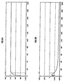
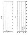
- Figs. 6A, 6B and 7A, 7B show the severe deformations of the frequency and phase response of a geophone all the more serious as the angle of inclination from its natural operating position is important.
- the comparison of Figures 8A, 8B with Figures 5A, 5B shows obviously that applying an appropriate compensation voltage to the hydrophone, significantly restores the responses, particularly in frequency and phase.
- the device according to the invention finds applications in particular in the field of seismic prospecting or active or passive surveillance underground deposits.
- US patents 5,363,094, EP 0 748 457 (US 5,724,311), or EP 0 921416 we are led to install often very large assemblies geophones in exploration and / or production wells, more or less deviated from the vertical (possibly horizontal in some portions).
- geophones multi-components for better discrimination of the elastic waves returned by discontinuities in the basement, it is common to install geophones multi-components (so-called triphones) to detect the components of signals received along three orthogonal axes.
- the device according to the invention allows in this kind of applications to provide the exact compensation required whatever the effective inclination of the geophone at depth use.
- the tilt compensation functions of geophones and acquisition of the captured signals can be carried out on the surface or be partially produced by local modules lowered into the wells at neighborhood of geophones.
- the device in wells more or less diverted. It is obvious that the device can be used in all applications where its effective orientation in operation is difficult controllable. This is particularly the case in applications where sensors are descended to the bottom of a body of water to be coupled with the formations underground.
Landscapes
- Remote Sensing (AREA)
- Physics & Mathematics (AREA)
- Engineering & Computer Science (AREA)
- General Physics & Mathematics (AREA)
- Life Sciences & Earth Sciences (AREA)
- Acoustics & Sound (AREA)
- Geology (AREA)
- General Life Sciences & Earth Sciences (AREA)
- Environmental & Geological Engineering (AREA)
- Geophysics (AREA)
- Radar, Positioning & Navigation (AREA)
- Geophysics And Detection Of Objects (AREA)
- Measurement Of Length, Angles, Or The Like Using Electric Or Magnetic Means (AREA)
- Transducers For Ultrasonic Waves (AREA)
- Gyroscopes (AREA)
- Paper (AREA)
- Constitution Of High-Frequency Heating (AREA)
- Details Of Connecting Devices For Male And Female Coupling (AREA)
- Investigating Or Analyzing Materials By The Use Of Ultrasonic Waves (AREA)
Applications Claiming Priority (2)
| Application Number | Priority Date | Filing Date | Title |
|---|---|---|---|
| FR9907242 | 1999-06-07 | ||
| FR9907242A FR2794531B1 (fr) | 1999-06-07 | 1999-06-07 | Dispositif capteur d'ondes elastiques compense electriquement des effets de l'inclinaison |
Publications (2)
| Publication Number | Publication Date |
|---|---|
| EP1061382A1 EP1061382A1 (fr) | 2000-12-20 |
| EP1061382B1 true EP1061382B1 (fr) | 2004-03-24 |
Family
ID=9546540
Family Applications (1)
| Application Number | Title | Priority Date | Filing Date |
|---|---|---|---|
| EP00401536A Expired - Lifetime EP1061382B1 (fr) | 1999-06-07 | 2000-05-31 | Dispositif capteur d'ondes élastiques compensé électriquement des effets de l'inclinaison |
Country Status (8)
| Country | Link |
|---|---|
| US (1) | US6412592B1 (enExample) |
| EP (1) | EP1061382B1 (enExample) |
| JP (1) | JP2001013256A (enExample) |
| AT (1) | ATE262684T1 (enExample) |
| CA (1) | CA2311180C (enExample) |
| DE (1) | DE60009211T2 (enExample) |
| FR (1) | FR2794531B1 (enExample) |
| NO (1) | NO20002871L (enExample) |
Families Citing this family (9)
| Publication number | Priority date | Publication date | Assignee | Title |
|---|---|---|---|---|
| AUPS225602A0 (en) * | 2002-05-10 | 2002-06-13 | Thales Underwater Systems Pty Limited | Improved seismic sensors |
| DE10344558A1 (de) * | 2003-09-25 | 2005-05-12 | Send Signal Elektronik Gmbh | Verfahren und Vorrichtung zur Erfassung von seismisch bedingten Bewegungen |
| FR2923615B1 (fr) * | 2007-11-12 | 2010-02-26 | Inst Francais Du Petrole | Source sismique permanente |
| US8199611B2 (en) * | 2009-02-05 | 2012-06-12 | Westerngeco L.L.C. | Deriving tilt-corrected seismic data in a multi-axis seismic sensor module |
| US9829595B2 (en) * | 2009-02-06 | 2017-11-28 | Westerngeco L.L.C. | Particle motion sensor-based streamer positioning system |
| US7684284B1 (en) | 2009-03-03 | 2010-03-23 | Saudi Arabian Oil Company | Steering and fixed angle geophone |
| US8125852B2 (en) * | 2009-05-25 | 2012-02-28 | Schlumberger Technology Corporation | Methods and systems for seismic signal detection |
| US8913464B2 (en) * | 2010-09-14 | 2014-12-16 | Schlumberger Technology Corporation | Methods and systems for seismic signal detection |
| CN111038382A (zh) * | 2019-12-30 | 2020-04-21 | 山东理工大学 | 一种基于重力球装置的车辆侧翻预警装置及方法 |
Family Cites Families (6)
| Publication number | Priority date | Publication date | Assignee | Title |
|---|---|---|---|---|
| US3878504A (en) * | 1973-09-21 | 1975-04-15 | Hall Sears Inc | Damped geophone |
| FR2247703A2 (en) * | 1973-10-15 | 1975-05-09 | Kerbiriou Daniel | Angular inclination checking instrument - pendulum running on curved contact strip forms arm of a wheatstone bridge |
| US4159464A (en) * | 1976-07-06 | 1979-06-26 | Western Geophysical Co. Of America | Geophone with damping coil |
| GB1559359A (en) * | 1977-12-29 | 1980-01-16 | Shell Int Research | Method and apparatus for reducing ground current interference with electrical signals representative of seismic wavesignals |
| US4525819A (en) * | 1982-12-06 | 1985-06-25 | Oyo Corporation, U.S.A. | Horizontal geophone transducer assembly |
| NL8802000A (nl) * | 1988-08-11 | 1990-03-01 | Jacobus Wilhelmus Petrus Van D | Geofoonstelsel. |
-
1999
- 1999-06-07 FR FR9907242A patent/FR2794531B1/fr not_active Expired - Fee Related
-
2000
- 2000-05-31 DE DE60009211T patent/DE60009211T2/de not_active Expired - Lifetime
- 2000-05-31 AT AT00401536T patent/ATE262684T1/de not_active IP Right Cessation
- 2000-05-31 EP EP00401536A patent/EP1061382B1/fr not_active Expired - Lifetime
- 2000-06-05 US US09/587,294 patent/US6412592B1/en not_active Expired - Lifetime
- 2000-06-06 CA CA002311180A patent/CA2311180C/fr not_active Expired - Fee Related
- 2000-06-06 NO NO20002871A patent/NO20002871L/no not_active Application Discontinuation
- 2000-06-06 JP JP2000169324A patent/JP2001013256A/ja active Pending
Also Published As
| Publication number | Publication date |
|---|---|
| US6412592B1 (en) | 2002-07-02 |
| CA2311180C (fr) | 2009-08-25 |
| CA2311180A1 (fr) | 2000-12-07 |
| FR2794531B1 (fr) | 2001-07-06 |
| JP2001013256A (ja) | 2001-01-19 |
| NO20002871L (no) | 2000-12-08 |
| NO20002871D0 (no) | 2000-06-06 |
| ATE262684T1 (de) | 2004-04-15 |
| FR2794531A1 (fr) | 2000-12-08 |
| DE60009211T2 (de) | 2004-08-12 |
| DE60009211D1 (de) | 2004-04-29 |
| EP1061382A1 (fr) | 2000-12-20 |
Similar Documents
| Publication | Publication Date | Title |
|---|---|---|
| US20050194201A1 (en) | Particle motion sensor for marine seismic sensor streamers | |
| US7926614B2 (en) | Particle motion sensor mounting for marine seismic sensor streamers | |
| US4334296A (en) | Seismic method and apparatus | |
| CN102308230B (zh) | 在多轴地震传感器模块中得出倾斜校正的地震数据 | |
| US7292504B2 (en) | Seismic sensors | |
| US9664807B2 (en) | Seismic sensor | |
| US20040042341A1 (en) | Apparatus and methods for multicomponent marine geophysical data gathering | |
| EP1061382B1 (fr) | Dispositif capteur d'ondes élastiques compensé électriquement des effets de l'inclinaison | |
| JPH0664084B2 (ja) | 光感震器 | |
| WO2010026386A2 (en) | Apparatus for sensing motion of a surface | |
| US7406002B2 (en) | Method and apparatus for the acquisition of seismic movements | |
| US5384753A (en) | Self-orienting seismic detector | |
| US9841519B2 (en) | Seismic sensor devices, systems, and methods including noise filtering | |
| US6725164B1 (en) | Hydrophone assembly | |
| US5475652A (en) | Dual gimbal geophone | |
| US10620332B2 (en) | Seismic data tilt angle correction method and system for multisensor streamer | |
| Liu et al. | A three-component borehole seismometer for earthquake seismology | |
| US20060291329A1 (en) | Processing seismic data representative of the acceleration wavefiled | |
| US11860327B2 (en) | Coherent noise-based seismic data verticalization correction method and system | |
| Goujon et al. | Stryde |
Legal Events
| Date | Code | Title | Description |
|---|---|---|---|
| PUAI | Public reference made under article 153(3) epc to a published international application that has entered the european phase |
Free format text: ORIGINAL CODE: 0009012 |
|
| AK | Designated contracting states |
Kind code of ref document: A1 Designated state(s): AT BE CH CY DE DK ES FI FR GB GR IE IT LI LU MC NL PT SE |
|
| AX | Request for extension of the european patent |
Free format text: AL;LT;LV;MK;RO;SI |
|
| 17P | Request for examination filed |
Effective date: 20010620 |
|
| AKX | Designation fees paid |
Free format text: AT BE CH CY DE DK ES FI FR GB GR IE IT LI LU MC NL PT SE |
|
| 17Q | First examination report despatched |
Effective date: 20030512 |
|
| GRAP | Despatch of communication of intention to grant a patent |
Free format text: ORIGINAL CODE: EPIDOSNIGR1 |
|
| GRAS | Grant fee paid |
Free format text: ORIGINAL CODE: EPIDOSNIGR3 |
|
| GRAA | (expected) grant |
Free format text: ORIGINAL CODE: 0009210 |
|
| AK | Designated contracting states |
Kind code of ref document: B1 Designated state(s): AT BE CH CY DE DK ES FI FR GB GR IE IT LI LU MC NL PT SE |
|
| PG25 | Lapsed in a contracting state [announced via postgrant information from national office to epo] |
Ref country code: IT Free format text: LAPSE BECAUSE OF FAILURE TO SUBMIT A TRANSLATION OF THE DESCRIPTION OR TO PAY THE FEE WITHIN THE PRE;WARNING: LAPSES OF ITALIAN PATENTS WITH EFFECTIVE DATE BEFORE 2007 MAY HAVE OCCURRED AT ANY TIME BEFORE 2007. THE CORRECT EFFECTIVE DATE MAY BE DIFFERENT FROM THE ONE RECORDED.SCRIBED TIME-LIMIT Effective date: 20040324 Ref country code: FI Free format text: LAPSE BECAUSE OF FAILURE TO SUBMIT A TRANSLATION OF THE DESCRIPTION OR TO PAY THE FEE WITHIN THE PRESCRIBED TIME-LIMIT Effective date: 20040324 Ref country code: CY Free format text: LAPSE BECAUSE OF FAILURE TO SUBMIT A TRANSLATION OF THE DESCRIPTION OR TO PAY THE FEE WITHIN THE PRESCRIBED TIME-LIMIT Effective date: 20040324 Ref country code: IE Free format text: LAPSE BECAUSE OF FAILURE TO SUBMIT A TRANSLATION OF THE DESCRIPTION OR TO PAY THE FEE WITHIN THE PRESCRIBED TIME-LIMIT Effective date: 20040324 Ref country code: AT Free format text: LAPSE BECAUSE OF FAILURE TO SUBMIT A TRANSLATION OF THE DESCRIPTION OR TO PAY THE FEE WITHIN THE PRESCRIBED TIME-LIMIT Effective date: 20040324 |
|
| REG | Reference to a national code |
Ref country code: GB Ref legal event code: FG4D Free format text: NOT ENGLISH |
|
| REG | Reference to a national code |
Ref country code: CH Ref legal event code: EP |
|
| GBT | Gb: translation of ep patent filed (gb section 77(6)(a)/1977) |
Effective date: 20040324 |
|
| REG | Reference to a national code |
Ref country code: IE Ref legal event code: FG4D Free format text: FRENCH |
|
| REF | Corresponds to: |
Ref document number: 60009211 Country of ref document: DE Date of ref document: 20040429 Kind code of ref document: P |
|
| PG25 | Lapsed in a contracting state [announced via postgrant information from national office to epo] |
Ref country code: CH Free format text: LAPSE BECAUSE OF NON-PAYMENT OF DUE FEES Effective date: 20040531 Ref country code: MC Free format text: LAPSE BECAUSE OF NON-PAYMENT OF DUE FEES Effective date: 20040531 Ref country code: LI Free format text: LAPSE BECAUSE OF NON-PAYMENT OF DUE FEES Effective date: 20040531 Ref country code: LU Free format text: LAPSE BECAUSE OF NON-PAYMENT OF DUE FEES Effective date: 20040531 Ref country code: BE Free format text: LAPSE BECAUSE OF NON-PAYMENT OF DUE FEES Effective date: 20040531 |
|
| PG25 | Lapsed in a contracting state [announced via postgrant information from national office to epo] |
Ref country code: GR Free format text: LAPSE BECAUSE OF FAILURE TO SUBMIT A TRANSLATION OF THE DESCRIPTION OR TO PAY THE FEE WITHIN THE PRESCRIBED TIME-LIMIT Effective date: 20040624 Ref country code: SE Free format text: LAPSE BECAUSE OF FAILURE TO SUBMIT A TRANSLATION OF THE DESCRIPTION OR TO PAY THE FEE WITHIN THE PRESCRIBED TIME-LIMIT Effective date: 20040624 Ref country code: DK Free format text: LAPSE BECAUSE OF FAILURE TO SUBMIT A TRANSLATION OF THE DESCRIPTION OR TO PAY THE FEE WITHIN THE PRESCRIBED TIME-LIMIT Effective date: 20040624 |
|
| PG25 | Lapsed in a contracting state [announced via postgrant information from national office to epo] |
Ref country code: ES Free format text: LAPSE BECAUSE OF FAILURE TO SUBMIT A TRANSLATION OF THE DESCRIPTION OR TO PAY THE FEE WITHIN THE PRESCRIBED TIME-LIMIT Effective date: 20040705 |
|
| REG | Reference to a national code |
Ref country code: IE Ref legal event code: FD4D |
|
| BERE | Be: lapsed |
Owner name: INSTITUT FRANCAIS DU PETROLE Effective date: 20040531 |
|
| REG | Reference to a national code |
Ref country code: CH Ref legal event code: PL |
|
| PLBE | No opposition filed within time limit |
Free format text: ORIGINAL CODE: 0009261 |
|
| STAA | Information on the status of an ep patent application or granted ep patent |
Free format text: STATUS: NO OPPOSITION FILED WITHIN TIME LIMIT |
|
| 26N | No opposition filed |
Effective date: 20041228 |
|
| PGFP | Annual fee paid to national office [announced via postgrant information from national office to epo] |
Ref country code: NL Payment date: 20070529 Year of fee payment: 8 |
|
| PGFP | Annual fee paid to national office [announced via postgrant information from national office to epo] |
Ref country code: GB Payment date: 20070611 Year of fee payment: 8 |
|
| PG25 | Lapsed in a contracting state [announced via postgrant information from national office to epo] |
Ref country code: PT Free format text: LAPSE BECAUSE OF NON-PAYMENT OF DUE FEES Effective date: 20040824 |
|
| GBPC | Gb: european patent ceased through non-payment of renewal fee |
Effective date: 20080531 |
|
| PG25 | Lapsed in a contracting state [announced via postgrant information from national office to epo] |
Ref country code: NL Free format text: LAPSE BECAUSE OF NON-PAYMENT OF DUE FEES Effective date: 20081201 |
|
| PG25 | Lapsed in a contracting state [announced via postgrant information from national office to epo] |
Ref country code: GB Free format text: LAPSE BECAUSE OF NON-PAYMENT OF DUE FEES Effective date: 20080531 |
|
| REG | Reference to a national code |
Ref country code: FR Ref legal event code: CD |
|
| REG | Reference to a national code |
Ref country code: DE Ref legal event code: R081 Ref document number: 60009211 Country of ref document: DE Owner name: IFP ENERGIES NOUVELLES, FR Free format text: FORMER OWNER: INSTITUT FRANCAIS DU PETROLE, RUEIL-MALMAISON, HAUTS-DE-SEINE, FR Effective date: 20110331 |
|
| PGFP | Annual fee paid to national office [announced via postgrant information from national office to epo] |
Ref country code: DE Payment date: 20130530 Year of fee payment: 14 |
|
| PGFP | Annual fee paid to national office [announced via postgrant information from national office to epo] |
Ref country code: FR Payment date: 20130430 Year of fee payment: 14 |
|
| REG | Reference to a national code |
Ref country code: DE Ref legal event code: R119 Ref document number: 60009211 Country of ref document: DE |
|
| REG | Reference to a national code |
Ref country code: FR Ref legal event code: ST Effective date: 20150130 |
|
| REG | Reference to a national code |
Ref country code: DE Ref legal event code: R119 Ref document number: 60009211 Country of ref document: DE Effective date: 20141202 |
|
| PG25 | Lapsed in a contracting state [announced via postgrant information from national office to epo] |
Ref country code: DE Free format text: LAPSE BECAUSE OF NON-PAYMENT OF DUE FEES Effective date: 20141202 |
|
| PG25 | Lapsed in a contracting state [announced via postgrant information from national office to epo] |
Ref country code: FR Free format text: LAPSE BECAUSE OF NON-PAYMENT OF DUE FEES Effective date: 20140602 |