EP1061357A2 - Method and apparatus for determining reflective optical quality - Google Patents
Method and apparatus for determining reflective optical quality Download PDFInfo
- Publication number
- EP1061357A2 EP1061357A2 EP00304744A EP00304744A EP1061357A2 EP 1061357 A2 EP1061357 A2 EP 1061357A2 EP 00304744 A EP00304744 A EP 00304744A EP 00304744 A EP00304744 A EP 00304744A EP 1061357 A2 EP1061357 A2 EP 1061357A2
- Authority
- EP
- European Patent Office
- Prior art keywords
- product
- image
- determining
- phase
- optical quality
- Prior art date
- Legal status (The legal status is an assumption and is not a legal conclusion. Google has not performed a legal analysis and makes no representation as to the accuracy of the status listed.)
- Granted
Links
Images


Classifications
-
- G—PHYSICS
- G01—MEASURING; TESTING
- G01N—INVESTIGATING OR ANALYSING MATERIALS BY DETERMINING THEIR CHEMICAL OR PHYSICAL PROPERTIES
- G01N21/00—Investigating or analysing materials by the use of optical means, i.e. using sub-millimetre waves, infrared, visible or ultraviolet light
- G01N21/84—Systems specially adapted for particular applications
- G01N21/88—Investigating the presence of flaws or contamination
- G01N21/95—Investigating the presence of flaws or contamination characterised by the material or shape of the object to be examined
- G01N21/958—Inspecting transparent materials or objects, e.g. windscreens
-
- G—PHYSICS
- G01—MEASURING; TESTING
- G01N—INVESTIGATING OR ANALYSING MATERIALS BY DETERMINING THEIR CHEMICAL OR PHYSICAL PROPERTIES
- G01N21/00—Investigating or analysing materials by the use of optical means, i.e. using sub-millimetre waves, infrared, visible or ultraviolet light
- G01N21/17—Systems in which incident light is modified in accordance with the properties of the material investigated
- G01N21/55—Specular reflectivity
-
- G—PHYSICS
- G01—MEASURING; TESTING
- G01N—INVESTIGATING OR ANALYSING MATERIALS BY DETERMINING THEIR CHEMICAL OR PHYSICAL PROPERTIES
- G01N21/00—Investigating or analysing materials by the use of optical means, i.e. using sub-millimetre waves, infrared, visible or ultraviolet light
- G01N21/84—Systems specially adapted for particular applications
- G01N21/88—Investigating the presence of flaws or contamination
- G01N21/8806—Specially adapted optical and illumination features
Definitions
- the invention relates to an apparatus and method for determining reflective optical quality of a reflective product using one or more grey-scale patterns, wherein the one or more patterns are reflected off of the product.
- a prior method for determining reflective optical quality of a reflective product involves reflecting a point light source off of the product and onto a white screen. A camera is then used to measure intensity variations of the light as seen on the screen. This method, however, is subject to errors if reflective properties of the product are not uniform. For example, if the product has a surface coating with variations in thickness, such variations are interpreted as variations in optical power.
- a method of determining reflective optical quality of a reflective product which includes reflecting a first grey-scale pattern off the product; obtaining a first image of the first pattern with an image pickup device after the first pattern has reflected off the product; and determining optical quality of the product based on data obtained from the first image.
- Exemplary grey-scale patterns that may be used to practice the method include sinusoidal gratings as well as sawtooth gratings.
- the grey-scale patterns may be projected at the product, or generated on a reference place and reflected off of the product. Consequently, the method may be used with a variety of product and test configurations.
- the method includes determining a phase for each of a plurality of pixels of the first image, wherein each pixel corresponds to a particular point on the product.
- One or more optical characteristics are then determined for each of a plurality of points on the product based on the phase at the corresponding pixel.
- the apparatus further includes an image pickup device for obtaining an image of the grey-scale pattern after the pattern has reflected off of the product, and an image analysing device in communication with the image pickup device.
- the image analysing device includes instructions for determining optical quality of the product based on the image of the grey-scale pattern.
- a method and apparatus embodying the invention has an advantage that it determines reflective optical quality of a reflective product at any and all points on the product. Furthermore, the method and apparatus provide accurate and repeatable results.
- Figure 1 shows an apparatus 10 according to the invention for determining reflective optical quality of a reflective product, such as a front windshield 12 for a motor vehicle.
- a reflective product such as a front windshield 12 for a motor vehicle.
- Other exemplary reflective products include mirrors, windows and any other shiny, relatively smooth object.
- the windshield 12 is supported on a generally flat surface 14 of an optionally rotatable work table 16.
- the apparatus 10 includes a projector 18 in communication with a computer 20.
- the projector 18 is used to project one or more grey-scale targets or patterns onto a reference plane, such as a screen 22, which is located behind the windshield 12 at a distance d o from the windshield 12.
- Grey-scale pattern refers to a pattern having a varying light intensity or colour profile, such as sinusoidal grating or sawtooth grating, and the pattern has a well defined phase at each point that is coded by colour.
- the projector 18 and computer 20 can be used to quickly generate and project a sequence of phase-shifted grey-scale patterns onto the screen 22.
- the apparatus 10 may include any suitable image generating device for providing one or more grey-scale patterns, such as a computer monitor, television monitor, painted pattern, or slide projector.
- the apparatus 10 further includes an image pickup device, such as a digital camera 24, for obtaining digital images of the grey-scale patterns.
- an image pickup device such as a digital camera 24, for obtaining digital images of the grey-scale patterns.
- the camera 24 is disposed in front of the windshield 12 at a distance d v from the windshield 12, as shown in Figure 1, so as to obtain digital images of the grey-scale patterns as reflected off of the windshield 12.
- the camera 24 is also in communication with the computer 20, and the camera 24 transmits signals to the computer 20 corresponding to the digital images.
- the computer 20 is used to process the signals so as to determine optical quality of the windshield 12 as explained below in greater detail.
- a method according to the invention for determining reflective optical quality of the windshield 12 involves determining one or more optical parameters or characteristics of the windshield 12 at discrete locations or points on the windshield 12. The optical characteristics are determined based on phase changes introduced to one or more grey-scale patterns by the windshield 12, as a result of the patterns being reflected off of the windshield 12.
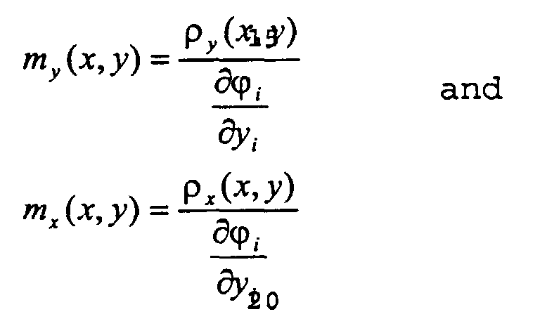
- Optical characteristics that may be determined include instantaneous apparent magnification, focal length, optical power, and astigmatism.
- wrapped vertical and horizontal phase distributions of images of the one or more grey scale patterns are first determined.
- vertical and horizontal phase distributions refer to vertical and horizontal phase values, respectively, at a plurality of pixels of the images.
- the phase distributions may be determined using any one of several known techniques.
- a phase-shift technique is preferably utilised.
- the projector 18 in order to determine the vertical phase distribution introduced by the windshield 12, the projector 18 first projects a single reference point onto the screen 22.
- the camera 24 then obtains an image of the reference point as reflected off of the windshield 12, and transfers the image to the computer 20 where it is stored.
- the projector 18 projects a horizontally oriented grey-scale pattern, such as a first grating 26 of horizontal lines having a sinusoidal intensity profile and a pitch p , onto the screen 22.
- the camera 24 then obtains an image of the first grating 26 as reflected off of the windshield 12, and the camera 24 transfers the image to the computer 20 where the image is stored.
- the reference point may be incorporated into the first grating 26, and a single image of the reference point and the first grating 26 may be obtained.
- the projector 18 in co-operation with the computer 20, shifts the first grating 26 vertically by a distance p/n to create a second, phase-shifted grating (not shown), where n is the desired number of phase-shifted gratings to be utilised in determining the vertical phase distribution. Furthermore, n should be greater than or equal to 3, and is preferably 4.
- the projector 18 then projects the second, phase-shifted grating onto the screen 22.
- the camera 24 obtains an image of the second, phase-shifted grating, and transfers the image to the computer 20 where the image is stored.
- the phase-shift technique involves generating a sequence of n phase-shifted grey-scale patterns, and obtaining images of each pattern within the sequence as reflected off of the windshield 12. Furthermore, each image comprises a plurality of pixels, and each pixel corresponds to a particular point on the windshield 12.
- this technique involves directing the camera 24 at the windshield 12 to obtain images of the patterns as reflected off of the windshield 12, it may be referred to as a view-at approach.
- the phase-shift technique may involve projecting a sequence of phase-shifted grey-scale patterns at or onto the windshield 12 such that the patterns are reflected off of the windshield 12 and onto the screen 22 or other reference plane.
- This alternative approach further involves obtaining images of the patterns as seen on the screen 22.
- Such an approach may be referred to as a project-at approach.
- the method involves reflecting one or more grey-scale patterns off the windshield 12, wherein such a description covers both view-at and project-at approaches.
- the computer 20 analyses the n images to determine vertical phase ⁇ y for each of the pixels of the images.
- the vertical phase ⁇ y for each pixel is determined based on light intensities at the same pixel location on the n different images, and the reference point is used to calibrate unwrapped vertical phase values.
- the above process is then repeated using the reference point and vertically oriented grey-scale patterns, such as a grating of vertical lines having a sinusoidal intensity and a known pitch, to determine horizontal phase ⁇ x for each of the pixels of the images.
- grey-scale patterns such as a grating of vertical lines having a sinusoidal intensity and a known pitch
- a Fourier transform technique is preferably utilised to determine the phase distributions.
- this technique involves obtaining an image of each pattern, and performing a Fourier transform of each image. Next, each Fourier transform is edited, and an inverse Fourier transform is performed to determine the vertical and horizontal phases for each pixel. Additional details regarding the Fourier transform technique may be found in "Fourier-Transform Method of Fringe-Pattern Analysis for Computer-Based Topography and Interferometry," by M. Takeda, H. Ina, and S. Kobayashi, which is hereby incorporated by reference.
- the camera 24 or other image pickup device has linear intensity response, and if the intensity profiles generated by the projector 18 or other image generating device are relatively accurate, then a technique that involves generating sawtooth gratings is preferably utilised to determine the phase distributions.
- the projector 18 generates a horizontally oriented sawtooth grating 27 on the screen 22.
- the camera 24 obtains an image of the sawtooth grating 27 as reflected off of the windshield 12, and the computer 20 acquires the image to determine a light intensity value I at each pixel (x,y) .
- the projector 18 generates a uniformly white target on the screen 22, the camera 24 obtains an image of the white target as reflected off of the windshield 12, and the computer 20 acquires the image to determine a maximum light intensity value I max at each pixel (x,y) .
- the projector 18 then generates a uniformly dark target on the screen 22, the camera 24 obtains an image of the dark target as reflected off of the windshield 12, and the computer 20 acquires the image to determine a minimum light intensity value I min at each pixel (x,y) .
- phase distributions can be determined relatively quickly.
- any other suitable technique for determining the phase distributions may be utilised, such as a phase synchronisation technique, a demodulation-convolution technique, a 3-point Fourier fit, or a polynomial fit fringe order technique.
- any of the techniques may involve view-at or project-at approaches.
- the computer 20 determines the partial derivatives of the vertical and horizontal phases for each pixel point.
- optical characteristics are determined for each point on the windshield 12 by determining optical characteristics at each corresponding pixel of the images based on the phase data obtained at each pixel.
- reference phase gradient at a pixel refers to the rate of phase change at pixel (x,y) when apparent magnification is 1.0.
- reference phase gradient is the rate of phase change at a particular pixel of an undistorted image.
- apparent magnification m a for a typical mirror is defined as the ratio of the angle subtended by the image of an object, which is referred to as image angle, to the angle subtended by the object, which is referred to as object angle.
- each image point will have a phase identical with the phase at the corresponding object point.
- the phase at a particular image point P i is identical to the phase at the corresponding object point P o .
- the reference phase gradients ⁇ y and ⁇ x may be determined using any suitable approach, such as a geometric approach. For simplicity, the discussion to follow will focus only on the relationship between the vertical reference phase gradient ⁇ y , and the configuration of the apparatus 10. A similar approach may also be utilised to determine the horizontal reference phase gradient ⁇ x .
- FIG. 5 shows the windshield 12 having a reference plane that is perpendicular to a target T , which is projected on screen 22.
- Target T comprises a grey-scale pattern having a varying light intensity profile and a pitch p .
- windshield 12 produces an image I of the target T .
- point P on target T can be seen as image point P '.
- ⁇ y ( x,y ) d ⁇ o dh p dh p d ⁇ v d ⁇ v dy
- ⁇ 0 (x,y) is the phase at pixel (x,y)
- ⁇ v is the angle of altitude and is optically equivalent to the previously described object angle ⁇ o
- h p is the height of target point P , which corresponds to pixel (x,y) , d ⁇ 0 / dh p 2 ⁇ / p
- d ⁇ v / dy is a constant ⁇ of the apparatus 10.
- the wrapped vertical phase distribution must be unwrapped using one of several known algorithms to obtain the unwrapped vertical phase ⁇ y , at each pixel.
- Figure 6 shows that point Q may be located on a facet of the windshield 12, wherein the facet has a surface normal n at an angle ⁇ to the reference plane. Furthermore, the point Q is within a distance ⁇ (not shown) of the reference plane, where ⁇ is much less than vertical distance h v , from the camera 24 to point Q .
- the error in calculating the reference phase gradient at point Q is approximately ⁇ / z v .
- Distance z v (or alternately angle ⁇ v ) can be determined based on a standard camera calibration which relates co-ordinate location (x,y ) to z v through function Z(x,y) .
- the reference phase gradients may also be measured using a procedure such as described below in detail.
- a test mirror that is optically flat is installed into a test arrangement.
- a reference point P 0 is displayed on the screen 22, and P 0 is used to define unwrapped phase ⁇ 0 .
- the picture point P 0 ' corresponding to point P 0 is then located.
- the reference phase gradient may then be determined from the following equation: where dh p / d ⁇ v may be determined as described above in detail.
- optical power OP at each pixel may be determined in the x and y directions.
- the focal length f must satisfy one of the two following conditions: either f ⁇ 0 , or f > 1/(1/d o + 1/d v ) . If f > 1/(1/d o + 1/d v ), then the windshield 12 functions as a positive lens and forms a real image. In this case, the camera 24 must be between the windshield 12 and the real image.
- OP y and OP x are determined based on the vertical position of the camera 24 relative to the windshield 12.
- optical power of the windshield 12 is a function of the angle the windshield 12 is tipped toward or away from the camera 24 or view point, it is beneficial to determine optical power based on a standard view angle.
- vertical and horizontal focal lengths f y and f x may be determined at each pixel (x,y) by taking the reciprocals of the vertical and horizontal optical powers OP y , and OP x , respectively, at each pixel ( x,y ).
- Focal lengths and optical powers in the x and y directions may then be determined for each pixel using this relationship.
- optical measure that accounts for the distance the observer will be from the windshield 12 during use.
- One such optical measure is standardised apparent magnification m s , which may be used to evaluate optical effects as perceived by the occupant when looking at an object at infinity while located a standard distance d s from the windshield 12.
- Another aspect of the invention involves evaluating astigmatic characteristics of the windshield 12. If the instantaneous apparent magnification m for a particular point (x,y) is not the same in all directions, then the windshield 12 is astigmatic at point (x,y) . In such a case, point (x,y) will have a maximum instantaneous apparent magnification a in a certain direction ⁇ , and a minimum instantaneous apparent magnification b in a direction perpendicular to ⁇ , where ⁇ is referred to as cylinder axis angle.
- Discrete phase differences may be used to determine maximum and minimum instantaneous apparent magnifications a and b , as well as cylinder angle ⁇ for each point on the windshield 12.
- Vertical disparity may also be evaluated for the windshield 12.
- Vertical disparity experienced by an observer looking at an object at infinity, is the difference in altitude angle between the direction to the image of the object as seen from the left eye of the observer, and the direction to the image of the object as seen from the right eye.
- the wrapped vertical phase distribution must be unwrapped using one of several known algorithms to obtain the unwrapped vertical phase ⁇ y at each pixel.
- the optical characteristics for each point on the windshield 12 may be evaluated to determine whether the optical quality of the windshield 12 is acceptable. For example, the optical characteristics for each point may be compared with predetermined, acceptable values.
- the computer 20 may generate one or more output images or profiles that graphically represent optical characteristics of the windshield 12. Furthermore, such images or profiles may be colour coded so that potential problem areas of the windshield 12 may be easily identified.
- the method and apparatus enable optical characteristics to be determined at all points on the windshield 12. Consequently, the apparatus and method of the invention provide a significantly more complete determination of optical quality of the windshield 12 compared with prior art apparatuses and methods. Because the optical characteristics of the windshield 12 are determined by the computer 20, the invention also provides an efficient and accurate determination of optical quality of the windshield 12. Furthermore, because the method preferably includes determining standardised apparent magnification, optical performance of the windshield 12 in use conditions may be effectively predicted.
Landscapes
- General Health & Medical Sciences (AREA)
- Health & Medical Sciences (AREA)
- Life Sciences & Earth Sciences (AREA)
- Chemical & Material Sciences (AREA)
- Analytical Chemistry (AREA)
- Biochemistry (AREA)
- Physics & Mathematics (AREA)
- General Physics & Mathematics (AREA)
- Immunology (AREA)
- Pathology (AREA)
- Testing Of Optical Devices Or Fibers (AREA)
- Investigating Or Analysing Materials By Optical Means (AREA)
- Length Measuring Devices By Optical Means (AREA)
Abstract
Description




Claims (8)
- A method of determining reflective optical quality of a reflective product, the method comprising:reflecting a first grey-scale pattern off the product;obtaining a first image of the first pattern with an image pickup device (24) after the first pattern has reflected off the product; anddetermining optical quality of the product based on data obtained from the first image.
- A method as claimed in claim 1, wherein reflecting a first grey-scale pattern comprises reflecting a first sinusoidal grating or a first sawtooth grating off the product.
- A method as claimed in claim 1 further comprising:reflecting a second grey-scale pattern off the product; andobtaining a second image of the second pattern with an image pickup device after the second pattern has reflected off the product;
wherein determining optical quality of the product further includes determining optical quality of the product based on the second image. - A method as claimed in claim 1 further comprising determining a phase for each of a plurality of pixels of the first image, wherein each pixel corresponds to a particular point on the product, and wherein determining optical quality of the product comprises determining optical quality of the product at each of a plurality of points on the product based on the phase at the corresponding pixel.
- A method as claimed in claim 1, wherein determining optical quality of the product comprises determining one or more optical characteristics for each of a plurality of points on the product, said optical characteristics including a) apparent magnification, b)focal length, c) optical power, d) standardised apparent magnification, e) cylindrical angle, f) vertical disparity and g) maximum apparent magnification and minimum apparent magnification.
- A method of determining reflective optical quality of a reflective product, the method comprising:projecting a sequence of phase-shifted sinusoidal gratings onto the product such that the gratings are reflected off of the product and onto a reference plane;obtaining an image of each of the gratings within the sequence as reflected off of the product;determining a phase for each of a plurality of pixels of the images, wherein each pixel corresponds to a particular point on the product; anddetermining optical quality of the product at each of a plurality of points on the product based on the phase at the corresponding pixel point.
- A method of determining reflective optical quality of a reflective product, the method comprising:positioning the product relative to an image generating device and an image pickup device such that light passing between the image generating device and the image pickup device reflects off of the product;generating a first grey-scale pattern with the image generating device;obtaining a first image of the first pattern with the image pickup device, wherein the first image is influenced by the product; anddetermining optical characteristics of the product based on the first image.
- An apparatus for determining reflective optical quality of a reflective product having light reflection properties, the apparatus comprising:an image generating device (18,20) for generating a grey-scale pattern;an image pickup device (24) for obtaining an image of the grey-scale pattern after the pattern has reflected off of the product; andan image analysing device (20) in communication with the image pickup device, the image analysing device including instructions for determining optical quality of the product based on the image.
Applications Claiming Priority (3)
| Application Number | Priority Date | Filing Date | Title |
|---|---|---|---|
| US332234 | 1989-03-31 | ||
| US09/332,234 US6100990A (en) | 1999-06-14 | 1999-06-14 | Method and apparatus for determining reflective optical quality using gray-scale patterns |
| CA002353301A CA2353301A1 (en) | 1999-06-14 | 2001-07-18 | Method and apparatus for determining reflective optical quality using gray-scale patterns |
Publications (3)
| Publication Number | Publication Date |
|---|---|
| EP1061357A2 true EP1061357A2 (en) | 2000-12-20 |
| EP1061357A3 EP1061357A3 (en) | 2002-04-10 |
| EP1061357B1 EP1061357B1 (en) | 2006-05-10 |
Family
ID=27789574
Family Applications (1)
| Application Number | Title | Priority Date | Filing Date |
|---|---|---|---|
| EP00304744A Expired - Lifetime EP1061357B1 (en) | 1999-06-14 | 2000-06-05 | Method and apparatus for determining reflective optical quality |
Country Status (4)
| Country | Link |
|---|---|
| US (1) | US6100990A (en) |
| EP (1) | EP1061357B1 (en) |
| JP (1) | JP2001066223A (en) |
| CA (1) | CA2353301A1 (en) |
Cited By (6)
| Publication number | Priority date | Publication date | Assignee | Title |
|---|---|---|---|---|
| EP1617175A1 (en) | 2004-07-16 | 2006-01-18 | Pilkington Plc | Glazing inspection |
| WO2019162233A1 (en) | 2018-02-22 | 2019-08-29 | Saint-Gobain Glass France | Method for simulating the optical power of a laminated glass |
| FR3090088A1 (en) | 2018-12-12 | 2020-06-19 | Saint-Gobain Glass France | Method for measuring the geometric deviations between the curved surfaces of a plurality of materials to be evaluated and a curved surface of a reference material |
| FR3101420A1 (en) | 2019-09-30 | 2021-04-02 | Saint-Gobain Glass France | Method for evaluating the optical quality of a delimited area of a glazing |
| EP4092409A1 (en) | 2021-05-20 | 2022-11-23 | Saint-Gobain Glass France | Method for detecting optical defects within windshield |
| EP4170327A1 (en) | 2021-10-22 | 2023-04-26 | Saint-Gobain Glass France | Method and system for detecting optical defects within a glass windshield |
Families Citing this family (40)
| Publication number | Priority date | Publication date | Assignee | Title |
|---|---|---|---|---|
| US6208412B1 (en) | 1999-06-14 | 2001-03-27 | Visteon Global Technologies, Inc. | Method and apparatus for determining optical quality |
| US6985231B2 (en) * | 2001-09-20 | 2006-01-10 | Strainoptics, Inc. | Method and apparatus for measuring the optical quality of a reflective surface |
| FR2830079B1 (en) * | 2001-09-26 | 2004-04-30 | Holo 3 | METHOD AND DEVICE FOR MEASURING AT LEAST ONE GEOMETRIC SIZE OF AN OPTICALLY REFLECTIVE SURFACE |
| JPWO2004013572A1 (en) * | 2002-08-01 | 2006-06-22 | 旭硝子株式会社 | Curved shape inspection method and apparatus |
| DE10300482B3 (en) * | 2003-01-08 | 2004-07-08 | Uwe Peter Braun | Method and device for detecting surface defects on workpieces with shiny surfaces |
| JP4883517B2 (en) * | 2004-11-19 | 2012-02-22 | 学校法人福岡工業大学 | Three-dimensional measuring apparatus, three-dimensional measuring method, and three-dimensional measuring program |
| CN101297192B (en) * | 2005-09-09 | 2012-05-30 | 萨克米伊莫拉机械合作社合作公司 | Method and device for visually monitoring objects |
| ES2320236T3 (en) * | 2005-09-12 | 2009-05-20 | PAUL MULLER GMBH & CO. KG UNTERNEHMENSBETEILIGUNGEN | TOOL HOLDER WITH A LEGIBLE DATA COLLECTION ELEMENT BY RADIO WAVES. |
| US7474415B2 (en) * | 2006-09-13 | 2009-01-06 | Chung Shan Institute Of Science And Technology, Armaments Bureau, M.N.D. | Measurement method of three-dimensional profiles and reconstruction system thereof using subpixel localization with color gratings and picture-in-picture switching on single display |
| US7471383B2 (en) * | 2006-12-19 | 2008-12-30 | Pilkington North America, Inc. | Method of automated quantitative analysis of distortion in shaped vehicle glass by reflected optical imaging |
| US7663745B2 (en) * | 2007-02-09 | 2010-02-16 | Xerox Corporation | Plural light source and camera to detect surface flaws |
| DE102007034689B4 (en) | 2007-07-12 | 2009-06-10 | Carl Zeiss Ag | Method and device for optically inspecting a surface on an object |
| EP2063260A1 (en) * | 2007-11-19 | 2009-05-27 | Lambda-X | Fourier transform deflectometry system and method |
| JP2009126249A (en) * | 2007-11-20 | 2009-06-11 | Honda Motor Co Ltd | Vehicle information display device |
| DE102007063530A1 (en) * | 2007-12-27 | 2009-07-16 | Carl Zeiss Ag | Method and device for optically inspecting a surface on an object |
| US9846689B2 (en) | 2008-01-29 | 2017-12-19 | Adobe Systems Incorporated | Method and system to provide portable database functionality in an electronic form |
| US8285025B2 (en) * | 2008-03-25 | 2012-10-09 | Electro Scientific Industries, Inc. | Method and apparatus for detecting defects using structured light |
| CN101676712B (en) * | 2008-09-16 | 2011-03-23 | 中茂电子(深圳)有限公司 | Optical detecting system and method thereof |
| FR2936605B1 (en) * | 2008-10-01 | 2014-10-31 | Saint Gobain | DEVICE FOR ANALYZING THE SURFACE OF A SUBSTRATE |
| DE102008064562A1 (en) | 2008-12-29 | 2010-07-08 | Carl Zeiss Oim Gmbh | Device for optically inspecting an at least partially shiny surface on an object |
| DE102009021733A1 (en) | 2009-05-12 | 2010-12-30 | Carl Zeiss Oim Gmbh | Apparatus and method for optically inspecting an article |
| DE102009038965A1 (en) | 2009-08-20 | 2011-03-03 | Carl Zeiss Oim Gmbh | Apparatus and method for optically inspecting a surface on an article |
| FR2951544A1 (en) | 2009-10-21 | 2011-04-22 | Saint Gobain | METHOD FOR ANALYZING THE QUALITY OF A GLAZING |
| FR2974414B1 (en) * | 2011-04-22 | 2013-04-12 | Saint Gobain | METHOD FOR ANALYZING THE QUALITY OF A GLAZING |
| DE102013216566A1 (en) * | 2013-08-21 | 2015-02-26 | Fraunhofer-Gesellschaft zur Förderung der angewandten Forschung e.V. | DEVICE AND METHOD FOR DETECTING AN AT LEAST PARTIAL MIRRORING SURFACE |
| WO2015058982A1 (en) * | 2013-10-24 | 2015-04-30 | Koninklijke Philips N.V. | Defect inspection system and method |
| FR3015033B1 (en) * | 2013-12-13 | 2015-12-04 | Saint Gobain | METHOD AND DEVICE FOR ANALYZING THE SURFACE OF A SUBSTRATE |
| DE102015207213B4 (en) * | 2015-04-21 | 2019-08-29 | Bayerische Motoren Werke Aktiengesellschaft | Apparatus and method for testing discs |
| US9933251B2 (en) | 2015-06-26 | 2018-04-03 | Glasstech, Inc. | Non-contact gaging system and method for contoured glass sheets |
| US9841276B2 (en) | 2015-06-26 | 2017-12-12 | Glasstech, Inc. | System and method for developing three-dimensional surface information corresponding to a contoured glass sheet |
| US9952039B2 (en) | 2015-06-26 | 2018-04-24 | Glasstech, Inc. | System and method for measuring reflected optical distortion in contoured panels having specular surfaces |
| US9851200B2 (en) | 2015-06-26 | 2017-12-26 | Glasstech, Inc. | Non-contact gaging system and method for contoured panels having specular surfaces |
| US9952037B2 (en) | 2015-06-26 | 2018-04-24 | Glasstech, Inc. | System and method for developing three-dimensional surface information corresponding to a contoured sheet |
| US9470641B1 (en) | 2015-06-26 | 2016-10-18 | Glasstech, Inc. | System and method for measuring reflected optical distortion in contoured glass sheets |
| CN105067639B (en) * | 2015-07-20 | 2018-03-27 | 丹阳市精通眼镜技术创新服务中心有限公司 | The eyeglass defect automatic detection device and method of a kind of Grating Modulation |
| CN105352439B (en) * | 2015-10-26 | 2018-01-30 | 上海交通大学 | Vehicle body parameter measuring system and method based on full raster structure |
| KR101945662B1 (en) * | 2016-06-27 | 2019-02-07 | 신닛테츠스미킨 카부시키카이샤 | Shape measuring device and shape measuring method |
| JP6917781B2 (en) | 2017-05-31 | 2021-08-11 | 株式会社キーエンス | Image inspection equipment |
| JP6967373B2 (en) | 2017-05-31 | 2021-11-17 | 株式会社キーエンス | Image inspection equipment |
| EP3899423B1 (en) * | 2018-12-21 | 2024-04-10 | Fraunhofer-Gesellschaft zur Förderung der angewandten Forschung e.V. | Device, measurement system and method for capturing an at least partly reflective surface using two reflection patterns |
Family Cites Families (44)
| Publication number | Priority date | Publication date | Assignee | Title |
|---|---|---|---|---|
| US4076426A (en) * | 1976-06-29 | 1978-02-28 | Rca Corporation | Method for inspecting cathode-ray-tube window for objectionable cord |
| JPS5953483B2 (en) * | 1978-01-27 | 1984-12-25 | 超エル・エス・アイ技術研究組合 | Mirror surface deformation distribution measuring device |
| US4255055A (en) * | 1979-05-11 | 1981-03-10 | Libbey-Owens-Ford Company | Surface inspection system for detecting flatness of planar sheet materials |
| US4285745A (en) * | 1979-08-01 | 1981-08-25 | Ppg Industries, Inc. | Method of determining optical quality of a laminated article |
| US4461570A (en) * | 1982-06-09 | 1984-07-24 | The United States Of America As Represented By The Secretary Of The Air Force | Method for dynamically recording distortion in a transparency |
| JPS60119404A (en) * | 1983-12-01 | 1985-06-26 | Nippon Sheet Glass Co Ltd | Inspecting device for distortion of plate glass |
| GB8424074D0 (en) * | 1984-09-24 | 1984-10-31 | British Aerospace | Testing light transmitting articles |
| JPS62239005A (en) * | 1986-04-11 | 1987-10-19 | Fuji Photo Film Co Ltd | Surface shape inspecting instrument |
| JPH0615968B2 (en) * | 1986-08-11 | 1994-03-02 | 伍良 松本 | Three-dimensional shape measuring device |
| DE3737632A1 (en) * | 1987-11-05 | 1989-05-24 | Sick Optik Elektronik Erwin | OPTICAL SURFACE RULING MEASURING DEVICE |
| US4895448A (en) * | 1988-01-13 | 1990-01-23 | Laird Richard P | Method and apparatus for determining the surface quality of an object |
| GB8826224D0 (en) * | 1988-11-09 | 1988-12-14 | Gersan Anstalt | Sensing shape of object |
| CH677972A5 (en) * | 1989-01-17 | 1991-07-15 | Kern & Co Ag | |
| DE3937559A1 (en) * | 1989-09-02 | 1991-03-14 | Flachglas Ag | METHOD FOR DETECTING OPTICAL ERRORS IN DISC FROM A TRANSPARENT MATERIAL, ESPECIALLY FROM GLASS |
| DE4007502A1 (en) * | 1990-03-09 | 1991-09-12 | Zeiss Carl Fa | METHOD AND DEVICE FOR CONTACTLESS MEASUREMENT OF OBJECT SURFACES |
| US5343294A (en) * | 1990-03-09 | 1994-08-30 | Carl-Zeiss-Stiftung | Method for analyzing periodic brightness patterns |
| DE4007500A1 (en) * | 1990-03-09 | 1991-09-12 | Zeiss Carl Fa | METHOD AND DEVICE FOR CONTACTLESS MEASUREMENT OF OBJECT SURFACES |
| AU8932391A (en) * | 1990-10-30 | 1992-05-26 | Simco/Ramic Corporation | Color line scan video camera for inspection system |
| US5146293A (en) * | 1991-05-13 | 1992-09-08 | The United States Of America As Represented By The Administrator Of The National Aeronautics And Space Administration | Phase-stepping fiber-optic projected fringe system for surface topography measurements |
| US5309222A (en) * | 1991-07-16 | 1994-05-03 | Mitsubishi Denki Kabushiki Kaisha | Surface undulation inspection apparatus |
| DE4130237A1 (en) * | 1991-09-11 | 1993-03-18 | Zeiss Carl Fa | METHOD AND DEVICE FOR THE THREE-DIMENSIONAL OPTICAL MEASUREMENT OF OBJECT SURFACES |
| US5175601A (en) * | 1991-10-15 | 1992-12-29 | Electro-Optical Information Systems | High-speed 3-D surface measurement surface inspection and reverse-CAD system |
| US5225890A (en) * | 1991-10-28 | 1993-07-06 | Gencorp Inc. | Surface inspection apparatus and method |
| US5311286A (en) * | 1992-04-01 | 1994-05-10 | Materials Technologies Corporation | Apparatus and method for optically measuring a surface |
| US5636025A (en) * | 1992-04-23 | 1997-06-03 | Medar, Inc. | System for optically measuring the surface contour of a part using more fringe techniques |
| JP2795595B2 (en) * | 1992-06-26 | 1998-09-10 | セントラル硝子株式会社 | Defect detection method for transparent plate |
| US5568258A (en) * | 1992-08-25 | 1996-10-22 | Asahi Glass Company Ltd. | Method and device for measuring distortion of a transmitting beam or a surface shape of a three-dimensional object |
| US5319445A (en) * | 1992-09-08 | 1994-06-07 | Fitts John M | Hidden change distribution grating and use in 3D moire measurement sensors and CMM applications |
| US5471307A (en) * | 1992-09-21 | 1995-11-28 | Phase Shift Technology, Inc. | Sheet flatness measurement system and method |
| US5343288A (en) * | 1992-11-23 | 1994-08-30 | Libbey-Owens-Ford Co. | Optical evaluation of automotive glass |
| US5367378A (en) * | 1993-06-01 | 1994-11-22 | Industrial Technology Institute | Highlighted panel inspection |
| US5581356A (en) * | 1993-06-14 | 1996-12-03 | Instruments Sa, Inc. | High purity tunable forensic light source |
| US5471297A (en) * | 1993-08-31 | 1995-11-28 | Asahi Glass Company Ltd. | Method of and apparatus for measuring optical distortion |
| DE4342830C1 (en) * | 1993-12-15 | 1995-04-20 | Haeusler Gerd | Device for producing strip-like light patterns |
| DE4415834C2 (en) * | 1994-05-05 | 2000-12-21 | Breuckmann Gmbh | Device for measuring distances and spatial coordinates |
| US5557410A (en) * | 1994-05-26 | 1996-09-17 | Lockheed Missiles & Space Company, Inc. | Method of calibrating a three-dimensional optical measurement system |
| FR2720831B3 (en) * | 1994-06-02 | 1996-07-12 | Saint Gobain Vitrage | Method for measuring the optical quality of a glazing. |
| US5581352A (en) * | 1994-09-22 | 1996-12-03 | Zeien; Robert | Phase shifting device with selectively activated grating generator |
| GB9420638D0 (en) * | 1994-10-13 | 1994-11-30 | Moore John H | Three-dimensional digitiser |
| JP3178644B2 (en) * | 1995-02-10 | 2001-06-25 | セントラル硝子株式会社 | Defect detection method for transparent plate |
| JPH08328150A (en) * | 1995-05-29 | 1996-12-13 | Nippondenso Co Ltd | Projector |
| AU683803B2 (en) * | 1995-10-17 | 1997-11-20 | Aluminum Company Of America | Electronic fringe analysis for determining surface contours |
| US5646733A (en) * | 1996-01-29 | 1997-07-08 | Medar, Inc. | Scanning phase measuring method and system for an object at a vision station |
| DE19643018B4 (en) * | 1996-10-18 | 2010-06-17 | Isra Surface Vision Gmbh | Method and device for measuring the course of reflective surfaces |
-
1999
- 1999-06-14 US US09/332,234 patent/US6100990A/en not_active Expired - Lifetime
-
2000
- 2000-06-05 EP EP00304744A patent/EP1061357B1/en not_active Expired - Lifetime
- 2000-06-14 JP JP2000178140A patent/JP2001066223A/en active Pending
-
2001
- 2001-07-18 CA CA002353301A patent/CA2353301A1/en not_active Abandoned
Cited By (12)
| Publication number | Priority date | Publication date | Assignee | Title |
|---|---|---|---|---|
| EP1617175A1 (en) | 2004-07-16 | 2006-01-18 | Pilkington Plc | Glazing inspection |
| US7995094B2 (en) | 2004-07-16 | 2011-08-09 | Pilkington Plc | Glazing inspection |
| WO2019162233A1 (en) | 2018-02-22 | 2019-08-29 | Saint-Gobain Glass France | Method for simulating the optical power of a laminated glass |
| US12026439B2 (en) | 2018-02-22 | 2024-07-02 | Saint-Gobain Glass France | Method for simulating the optical power of a laminated glass |
| FR3090088A1 (en) | 2018-12-12 | 2020-06-19 | Saint-Gobain Glass France | Method for measuring the geometric deviations between the curved surfaces of a plurality of materials to be evaluated and a curved surface of a reference material |
| FR3101420A1 (en) | 2019-09-30 | 2021-04-02 | Saint-Gobain Glass France | Method for evaluating the optical quality of a delimited area of a glazing |
| WO2021063847A1 (en) | 2019-09-30 | 2021-04-08 | Saint-Gobain Glass France | Method for evaluating the optical quality of a delimited zone of a glazing |
| US12130244B2 (en) | 2019-09-30 | 2024-10-29 | Saint-Gobain Glass France | Method for evaluating the optical quality of a delineated region of a glazing |
| EP4092409A1 (en) | 2021-05-20 | 2022-11-23 | Saint-Gobain Glass France | Method for detecting optical defects within windshield |
| WO2022243288A1 (en) | 2021-05-20 | 2022-11-24 | Saint-Gobain Glass France | Method for detecting optical defects within windshield |
| EP4170327A1 (en) | 2021-10-22 | 2023-04-26 | Saint-Gobain Glass France | Method and system for detecting optical defects within a glass windshield |
| WO2023067097A1 (en) | 2021-10-22 | 2023-04-27 | Saint-Gobain Glass France | Method and system for detecting optical defects within a glass windshield |
Also Published As
| Publication number | Publication date |
|---|---|
| JP2001066223A (en) | 2001-03-16 |
| US6100990A (en) | 2000-08-08 |
| EP1061357A3 (en) | 2002-04-10 |
| EP1061357B1 (en) | 2006-05-10 |
| CA2353301A1 (en) | 2003-01-18 |
Similar Documents
| Publication | Publication Date | Title |
|---|---|---|
| EP1061357B1 (en) | Method and apparatus for determining reflective optical quality | |
| EP1065498A2 (en) | Method and apparatus for determining optical quality | |
| US11105617B2 (en) | Hybrid light measurement method for measuring three-dimensional profile | |
| KR102771154B1 (en) | Three-dimensional sensor with counterposed channels | |
| Felipe-Sese et al. | Simultaneous in-and-out-of-plane displacement measurements using fringe projection and digital image correlation | |
| US6252623B1 (en) | Three dimensional imaging system | |
| CN104903680B (en) | Methods for controlling the linear dimensions of 3D objects | |
| US20100177319A1 (en) | Optical imaging of physical objects | |
| JP2000508066A (en) | Method and apparatus for measuring the shape of an object | |
| Etchepareborda et al. | Random laser speckle pattern projection for non-contact vibration measurements using a single high-speed camera | |
| CN104713497A (en) | Phase offset calibration method, 3D shape detection method, system and projection system | |
| US11300402B2 (en) | Deriving topology information of a scene | |
| JP2714152B2 (en) | Object shape measurement method | |
| CN106979758A (en) | A kind of three-dimensional measuring apparatus and method | |
| JP2000111490A (en) | Painted surface detection device | |
| JP2010151842A (en) | Three-dimensional shape measuring instrument and three-dimensional shape measurement method | |
| Liu et al. | Three-dimensional measurement for specular reflection object based on adaptive fringe projection and phase measuring profilometry | |
| RU125335U1 (en) | DEVICE FOR MONITORING LINEAR SIZES OF THREE-DIMENSIONAL OBJECTS | |
| CN118654600A (en) | A method and system for eliminating highlights based on a super surface | |
| JPH10281933A (en) | Method and device for estimating image quality of hologram | |
| KR102677574B1 (en) | Apparatus and method for 3D measurement of freeform surfaces based on line scan deflectometry using composite patterns under moving situation | |
| KR100328025B1 (en) | Apparatus and method for measuring shape of cold rolled steel sheet using sinusoidal stripe phase shift | |
| Suzuki et al. | Small rotation angle measurement using an imaging method | |
| JPH07218226A (en) | Three-dimesional measuring apparatus of surface shape | |
| Han et al. | Combined stereovision and phase shifting method: use of a visibility-modulated fringe pattern |
Legal Events
| Date | Code | Title | Description |
|---|---|---|---|
| PUAI | Public reference made under article 153(3) epc to a published international application that has entered the european phase |
Free format text: ORIGINAL CODE: 0009012 |
|
| AK | Designated contracting states |
Kind code of ref document: A2 Designated state(s): DE FR GB Kind code of ref document: A2 Designated state(s): AT BE CH CY DE DK ES FI FR GB GR IE IT LI LU MC NL PT SE |
|
| AX | Request for extension of the european patent |
Free format text: AL;LT;LV;MK;RO;SI |
|
| PUAL | Search report despatched |
Free format text: ORIGINAL CODE: 0009013 |
|
| AK | Designated contracting states |
Kind code of ref document: A3 Designated state(s): AT BE CH CY DE DK ES FI FR GB GR IE IT LI LU MC NL PT SE |
|
| AX | Request for extension of the european patent |
Free format text: AL;LT;LV;MK;RO;SI |
|
| RIC1 | Information provided on ipc code assigned before grant |
Free format text: 7G 01N 21/896 A, 7G 01B 11/25 B |
|
| 17P | Request for examination filed |
Effective date: 20020910 |
|
| AKX | Designation fees paid |
Free format text: DE FR GB |
|
| 17Q | First examination report despatched |
Effective date: 20031118 |
|
| GRAP | Despatch of communication of intention to grant a patent |
Free format text: ORIGINAL CODE: EPIDOSNIGR1 |
|
| GRAS | Grant fee paid |
Free format text: ORIGINAL CODE: EPIDOSNIGR3 |
|
| GRAA | (expected) grant |
Free format text: ORIGINAL CODE: 0009210 |
|
| AK | Designated contracting states |
Kind code of ref document: B1 Designated state(s): DE FR GB |
|
| REG | Reference to a national code |
Ref country code: GB Ref legal event code: FG4D |
|
| REF | Corresponds to: |
Ref document number: 60027818 Country of ref document: DE Date of ref document: 20060614 Kind code of ref document: P |
|
| ET | Fr: translation filed | ||
| PLBE | No opposition filed within time limit |
Free format text: ORIGINAL CODE: 0009261 |
|
| STAA | Information on the status of an ep patent application or granted ep patent |
Free format text: STATUS: NO OPPOSITION FILED WITHIN TIME LIMIT |
|
| 26N | No opposition filed |
Effective date: 20070213 |
|
| REG | Reference to a national code |
Ref country code: GB Ref legal event code: 732E |
|
| PGFP | Annual fee paid to national office [announced via postgrant information from national office to epo] |
Ref country code: GB Payment date: 20130529 Year of fee payment: 14 |
|
| PGFP | Annual fee paid to national office [announced via postgrant information from national office to epo] |
Ref country code: FR Payment date: 20130618 Year of fee payment: 14 |
|
| PGFP | Annual fee paid to national office [announced via postgrant information from national office to epo] |
Ref country code: DE Payment date: 20130628 Year of fee payment: 14 |
|
| REG | Reference to a national code |
Ref country code: DE Ref legal event code: R119 Ref document number: 60027818 Country of ref document: DE |
|
| GBPC | Gb: european patent ceased through non-payment of renewal fee |
Effective date: 20140605 |
|
| REG | Reference to a national code |
Ref country code: DE Ref legal event code: R119 Ref document number: 60027818 Country of ref document: DE Effective date: 20150101 |
|
| REG | Reference to a national code |
Ref country code: FR Ref legal event code: ST Effective date: 20150227 |
|
| PG25 | Lapsed in a contracting state [announced via postgrant information from national office to epo] |
Ref country code: DE Free format text: LAPSE BECAUSE OF NON-PAYMENT OF DUE FEES Effective date: 20150101 |
|
| PG25 | Lapsed in a contracting state [announced via postgrant information from national office to epo] |
Ref country code: GB Free format text: LAPSE BECAUSE OF NON-PAYMENT OF DUE FEES Effective date: 20140605 Ref country code: FR Free format text: LAPSE BECAUSE OF NON-PAYMENT OF DUE FEES Effective date: 20140630 |