EP1061356B1 - In-line particulate detector - Google Patents
In-line particulate detector Download PDFInfo
- Publication number
- EP1061356B1 EP1061356B1 EP00304861A EP00304861A EP1061356B1 EP 1061356 B1 EP1061356 B1 EP 1061356B1 EP 00304861 A EP00304861 A EP 00304861A EP 00304861 A EP00304861 A EP 00304861A EP 1061356 B1 EP1061356 B1 EP 1061356B1
- Authority
- EP
- European Patent Office
- Prior art keywords
- photodiode
- housing
- particulate detector
- line
- fuel
- Prior art date
- Legal status (The legal status is an assumption and is not a legal conclusion. Google has not performed a legal analysis and makes no representation as to the accuracy of the status listed.)
- Expired - Lifetime
Links
Images


Classifications
-
- G—PHYSICS
- G01—MEASURING; TESTING
- G01N—INVESTIGATING OR ANALYSING MATERIALS BY DETERMINING THEIR CHEMICAL OR PHYSICAL PROPERTIES
- G01N15/00—Investigating characteristics of particles; Investigating permeability, pore-volume or surface-area of porous materials
- G01N15/10—Investigating individual particles
- G01N15/14—Optical investigation techniques, e.g. flow cytometry
-
- G—PHYSICS
- G01—MEASURING; TESTING
- G01N—INVESTIGATING OR ANALYSING MATERIALS BY DETERMINING THEIR CHEMICAL OR PHYSICAL PROPERTIES
- G01N21/00—Investigating or analysing materials by the use of optical means, i.e. using sub-millimetre waves, infrared, visible or ultraviolet light
- G01N21/17—Systems in which incident light is modified in accordance with the properties of the material investigated
- G01N21/47—Scattering, i.e. diffuse reflection
- G01N21/49—Scattering, i.e. diffuse reflection within a body or fluid
- G01N21/53—Scattering, i.e. diffuse reflection within a body or fluid within a flowing fluid, e.g. smoke
- G01N21/532—Scattering, i.e. diffuse reflection within a body or fluid within a flowing fluid, e.g. smoke with measurement of scattering and transmission
-
- G—PHYSICS
- G01—MEASURING; TESTING
- G01N—INVESTIGATING OR ANALYSING MATERIALS BY DETERMINING THEIR CHEMICAL OR PHYSICAL PROPERTIES
- G01N21/00—Investigating or analysing materials by the use of optical means, i.e. using sub-millimetre waves, infrared, visible or ultraviolet light
- G01N21/84—Systems specially adapted for particular applications
- G01N21/85—Investigating moving fluids or granular solids
Definitions
- This invention relates generally to particulate detectors and more specifically to in-line particulate and liquid droplet detectors for natural gas lines.
- Industrial power generation gas turbine engines include a compressor for compressing air that is mixed with fuel and ignited in a combustor for generating combustion gases.
- the combustion gases flow to a turbine that extracts energy for driving a shaft to power the compressor and produces output power for powering an electrical generator, for example.
- the turbine is typically operated for extended periods of time at a relatively high base load for powering the generator to produce electrical power to a utility grid, for example. Exhaust emissions from the combustion gases are therefore a concern and are subjected to mandated limits.
- Low emission combustion systems are designed to produce low emissions and high combustion efficiency while burning natural gas fuel that is assumed to be free of liquid or solid contaminants.
- pipeline gas is at times contaminated with condensed liquid hydrocarbons (to varying degrees) as well as other solid particulate contaminants. It is highly desirable to minimize the effects of these contaminants on gas turbine combustor performance, either by their removal or by robust combustor design.
- the presence of varying amounts of liquid hydrocarbons in the fuel source has become an increasingly important operational issue.
- the quality of natural gas supplied to gas turbines is an important variable in turbine performance.
- the principle component of natural gas is methane, which typically accounts for over 90% of the mass.
- Other components in natural gas may include heavier hydrocarbons, oils and water.
- the chemical composition of the gas is particularly important because of the potential for ignition to occur within the mixing zone.
- the effect of heavier hydrocarbons and oils in the gas stream is to lower the autoignition temperature of the mixture. Natural gas with high concentrations of these species is more likely to ignite in the mixing zone of the combustors than in an intended flame holder region.
- US 4,420,256 A discloses a particle detector comprising a housing having an inner flow portion permitting fluid to flow therethrough, a light source for emitting a light beam within said inner flow portion, a first photodetector disposed opposite and substantially normal to said light source such that substantially full strength of an unimpeded emitted light beam is detected by said first photodetector, a second photodetector disposed adjacent said first photodetector and offset from a normal unimpeded path between said light source and said first photodetector such that a baseline level of an unimpeded emitted light beam is detected by said second photodetector, and a calculating unit coupled to said first and second photodetectors and programmed to calculate quantities A and B proportional to particle concentration and radius, respectively, wherein said quantities A and B are calculated based on a ratio of the d.c. signal components from the two photodetectors.
- the invention is defined in claim 1.
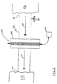
- a pipeline 50 comprising an inlet 52 and an outlet 54 provides fluid communication between a fuel source 56 and a fuel consumer 10, for example a power turbine as shown in Fig. 1.
- a shut off valve 58 is typically disposed within pipeline 50, which valve 58 is movable between a fully open position and a fully closed position to allow or prevent fuel flow, respectively, from fuel source 56 to fuel consumer 10.
- an in-line particulate detector assembly 100 is adapted to be coupled to pipeline 50.
- the in-line particulate detector assembly 100 is embodied within a housing 102, for example a flange, that is disposed between adjacent portions of pipeline 50 to permit a continuous fuel flow 60 from fuel source 56 to fuel consumer 10.
- In-line particulate detector assembly 100 may also be directly positioned within a sidewall of pipeline 50.
- In-line particulate detector assembly 100 comprises housing 102, a light source 104, a first photodetector 106 and a second photodetector 108, as shown in FIG. 2.
- Light source 104 is positioned within housing 102 so as to enable light source 104 to emit a light beam 110 within an interior flow portion 112 of housing 102.
- First photodetector 106 is disposed opposite light source 104 so as to be optically coupled with light source 104.
- first photodetector 106 is disposed within housing 102 opposite and substantially normal to light source 104 such that most of the full strength of a generated light beam 110 is detected by first photodetector 106 when little or no particles or other interfering substances are located within interior flow portion 112 of housing 102.
- Second photodetector 108 is positioned within housing 102 adjacent to first photodetector 106. Second photodetector 108 is angularly offset from the normal unimpeded path of light between light source 104 and first photodetector 106, typically in the range between about 10° to about 60°. A key feature of this invention is the placement of second photodetector 108 slightly offset from light source 104. This offset position maximizes the collection of scattered light while retaining the simplicity of a single photodetector for scattered light detection.
- second photodetector 108 When little or no particles or other interfering substances are present within a fuel flow 60 traveling through interior flow portion 112 of housing 102, second photodetector 108 will sense a baseline level of light reflected from first photodetector 106 and Rayleigh scattering from gas molecules within fuel flow 60 (Fig. 1).
- first and second photodetectors 106, 108 provide a sensitive measure of the presence of particles and the amount of particles in fuel flow 60.
- fuel flow 60 comprises a natural gas, for example, methane, or propane, hexane, heptane, gas derived from coal, or the like. As discussed above, fuel flow 60 flows from fuel source 56 to fuel consumer 10 through pipeline 50 and interior flow portion 112 of housing 102.
- a natural gas for example, methane, or propane, hexane, heptane, gas derived from coal, or the like.
- Circuitry 114 is coupled to first and second photodetectors 106, 108 to measure the presence and quantity of particles when exposed to a fuel flow 60 between inlet 52 and outlet 54.
- circuitry 114 includes a power input, an amplifier and a processor for monitoring the signals from first and second photodetectors 106, 108 and generating an output signal. In another embodiment, circuitry 114 further comprises an amplifier and a computer for processing signals and generating a particulate level report or display.
- a control structure is inputted into circuitry 114, for example, by programming into memory of an application specific integrated circuit (ASIC) or is embedded in the form of algorithms in one or more computers such as a work station.
- ASIC application specific integrated circuit
- Other types of computers can be used, however, such as a minicomputer, a microcomputer, or a supercomputer, for example.
- the programming or algorithm performed may be programmed in C, C++, JAVA, Basic, MATLAB, FORTRAN, or other programming languages.
- circuitry 114 may initiate a system control. For example, limit fuel consumer 10, to low load operation. Additionally, if the ratio of light intensities rises above a setpoint, circuitry 114 may initiate an algorithm to look at combustion system anomalies, or, for example, sound an alarm or otherwise alert a system user.
- the instant invention is shown connected to a pipeline 50 for a fuel consumer 10, this invention could also be applied to monitor the quality of process gases, not necessarily intended for combustion. Additionally, the instant invention can be utilized for monitoring gas quality at the exit of a cryogenic gas processing system; monitoring gas quality at the custody transfer point between a gas producer and a gas transmission company; monitoring gas quality at the custody transfer point between a gas transmission company and a local distribution company; monitoring gas quality at a compressor station used to compress gas for natural gas powered vehicles, or the like.
- Light source 104 may comprise a laser diode light source or the like.
- the advantage of laser light over a collimated beam of non-laser light is the combination of low divergence angle with high intensity and relatively high electrical efficiency.
- Light can be collimated from a conventional light source by spacing two slits far apart, however, the intensity is low relative to the power generated by the source.
- Photodetectors 106, 108 may comprise photodiodes or the like.
- the advantage of solid state photodiodes is that they are inexpensive, very compact, and durable. While photodiodes are not as sensitive as traditional photomultipler tubes, with proper amplification, the sensitivity of photodiodes is sufficient to sense low levels of particles.
- a light trap is disposed adjacent first photodetector 106 to minimize the light reflected therefrom.
- ball valves 116 and sight glasses 118 are disposed between light source 104 and interior flow portion 112 and between each photodetector 106, 108 and interior flow portion 112 to make in-line particulate detector assembly 100 serviceable in the field without interruption of fuel flow 60.
- second photodetector 108 is positioned in close proximity to internal flow portion 112 of housing 102 to maximize the intensity of scattered light reaching second photodetector 108.
- a remote in-line particulate detector assembly 300 is shown in FIG. 3. This embodiment is similar in all respects to the in-line particulate detector assembly in FIGs. 1 and 2, except that circuitry 114 comprises a remote unit for transmitting signals from assembly 300.
- a remote station 304 provides a communication base for interaction with a respective remote unit.
- Remote station 304 typically comprises a central interface 306, a radio frequency (RF) front-end 308, an antenna, and user interface related peripheral devices including a user interface 312, a display 314, data storage 316 and a printer 318 for enabling a user to input or extract relevant information into central interface 306.
- Peripheral devices as defined in this application include any device for storing particulate measurement or analysis information and intelligibly communicating the same to a system user, and include such devices as printers, hard disk drives, floppy disk drives, cathode ray tubes (CRTs) and keyboards. While only one set of respective peripheral devices is shown for a respective central interface 306, any number of peripheral drives may be utilized and are within the scope of the instant invention.
- a communications system 320 such as a "geo-synchronous" "L-band” satellite system, a “Little Leo” satellite system, a two-way paging system, a modem connection or any communication system capable of two-way communication between remote station 304 and a respective remote unit.
Landscapes
- Chemical & Material Sciences (AREA)
- Physics & Mathematics (AREA)
- Health & Medical Sciences (AREA)
- Life Sciences & Earth Sciences (AREA)
- Analytical Chemistry (AREA)
- Biochemistry (AREA)
- General Health & Medical Sciences (AREA)
- General Physics & Mathematics (AREA)
- Immunology (AREA)
- Pathology (AREA)
- Dispersion Chemistry (AREA)
- Investigating Or Analysing Materials By Optical Means (AREA)
Applications Claiming Priority (2)
| Application Number | Priority Date | Filing Date | Title |
|---|---|---|---|
| US333181 | 1994-11-02 | ||
| US09/333,181 US6710878B1 (en) | 1999-06-14 | 1999-06-14 | In-line particulate detector |
Publications (3)
| Publication Number | Publication Date |
|---|---|
| EP1061356A2 EP1061356A2 (en) | 2000-12-20 |
| EP1061356A3 EP1061356A3 (en) | 2002-04-10 |
| EP1061356B1 true EP1061356B1 (en) | 2007-07-11 |
Family
ID=23301677
Family Applications (1)
| Application Number | Title | Priority Date | Filing Date |
|---|---|---|---|
| EP00304861A Expired - Lifetime EP1061356B1 (en) | 1999-06-14 | 2000-06-08 | In-line particulate detector |
Country Status (6)
| Country | Link |
|---|---|
| US (1) | US6710878B1 (https=) |
| EP (1) | EP1061356B1 (https=) |
| JP (1) | JP2001027599A (https=) |
| KR (1) | KR100636928B1 (https=) |
| DE (1) | DE60035460T2 (https=) |
| TW (1) | TW463044B (https=) |
Families Citing this family (34)
| Publication number | Priority date | Publication date | Assignee | Title |
|---|---|---|---|---|
| GB2371858B (en) * | 2001-02-05 | 2004-10-13 | Abb Offshore Systems Ltd | Monitoring particles in a fluid flow |
| DE10226334B4 (de) * | 2002-06-13 | 2005-09-01 | Pari GmbH Spezialisten für effektive Inhalation | Vorrichtung zur Erfassung von Parametern eines Aerosols, insbesondere bei Inhalationstherapiegeräten |
| US6903818B2 (en) * | 2002-10-28 | 2005-06-07 | Particle Measuring Systems, Inc. | Low noise intracavity laser particle counter |
| GB0323055D0 (en) * | 2003-10-02 | 2003-11-05 | Unidata Europ Ltd | Particulate detector |
| GB0500687D0 (en) * | 2005-01-14 | 2005-02-23 | Unidata Europ Ltd | Particulate detector |
| JP4673887B2 (ja) * | 2005-04-28 | 2011-04-20 | トヨタ自動車株式会社 | 排ガス分析装置 |
| DE102005025181A1 (de) | 2005-06-01 | 2006-12-07 | Sick Engineering Gmbh | Partikelkonzentrations-Messvorrichtung und Messverfahren |
| US20080127728A1 (en) * | 2006-11-30 | 2008-06-05 | General Electric Company | Mechanical response based detonation velocity measurement system |
| US7854158B2 (en) | 2006-12-28 | 2010-12-21 | Perry Equipment Corporation | Systems and methods for measurement and analysis of pipeline contaminants |
| WO2009002322A1 (en) * | 2007-06-28 | 2008-12-31 | Perry Equipment Corporation | Systems and methods for remote monitoring of contaminants in fluids |
| US7924424B2 (en) * | 2007-10-11 | 2011-04-12 | Ecolab Usa Inc. | Optical product detection sensor |
| US8004683B2 (en) * | 2007-10-11 | 2011-08-23 | Ecolab Usa Inc. | Optical product detection sensor |
| CN101910821B (zh) | 2007-12-04 | 2012-09-05 | 粒子监测系统有限公司 | 非正交粒子检测系统和方法 |
| JP2011529575A (ja) * | 2008-07-31 | 2011-12-08 | ファセト・イベリカ・ソシエダッド・アノニマ | 燃料品質を追跡測定できる遠隔システム |
| US8498750B2 (en) * | 2008-12-23 | 2013-07-30 | Velcon Filters, Llc | System for monitoring a transient fluid |
| US20100201984A1 (en) * | 2009-02-11 | 2010-08-12 | Cyberoptics Semiconductor, Inc. | In-line high pressure particle sensing system |
| US20110008737A1 (en) * | 2009-06-15 | 2011-01-13 | General Electric Company | Optical sensors for combustion control |
| US8456634B2 (en) * | 2009-06-15 | 2013-06-04 | General Electric Company | Optical interrogation sensors for combustion control |
| CN102687018B (zh) | 2009-11-16 | 2015-07-15 | 硅生物装置有限公司 | 化验用过滤装置 |
| US9433939B2 (en) * | 2010-08-27 | 2016-09-06 | Hewlett-Packard Development Company, L.P. | Liquid dispensing assembly frame |
| US9645162B2 (en) | 2010-08-27 | 2017-05-09 | Hewlett-Packard Development Company, L.P. | Automated assay fluid dispensing |
| WO2012048288A1 (en) * | 2010-10-07 | 2012-04-12 | Silicon Biodevices, Inc. | Magnetic particle based biosensor |
| EP2708872A1 (de) * | 2012-09-18 | 2014-03-19 | Linde Aktiengesellschaft | Verfahren und Vorrichtung zur Erkennung von sich bewegenden Objekten in einem Gasstrom |
| US20160258877A1 (en) * | 2015-03-05 | 2016-09-08 | The Petroleum Institute | Online Measurement Of Black Powder In Gas And Oil Pipelines |
| US10422754B2 (en) * | 2015-03-05 | 2019-09-24 | Khalifa University of Science and Technology | Online measurement of black powder in gas and oil pipelines |
| CA3072447A1 (en) | 2017-08-10 | 2019-02-14 | Advanced Polymer Monitoring Technologies, Inc., Dba/ Fluence Analytics | Devices and methods for characterization and control of biopolymers and synthetic polymers during manufacturing |
| WO2019152079A1 (en) | 2018-01-31 | 2019-08-08 | Parker-Hannifin Corporation | Sensor system for detecting contaminant in fluid |
| DE102018203254A1 (de) * | 2018-03-05 | 2019-02-28 | Continental Automotive Gmbh | Verfahren und Vorrichtung zur Bestimmung von zumindest einer Eigenschaft eines Fluids |
| KR102026983B1 (ko) * | 2018-03-29 | 2019-09-30 | 두산중공업 주식회사 | 가스터빈 내 파이프를 통과하는 유체의 오염물을 모니터링 하는 시스템 및 그 방법 |
| DE102018214221B4 (de) * | 2018-08-22 | 2020-10-15 | Vitesco Technologies GmbH | Verfahren zum Überprüfen einer zum Bestimmen von zumindest einer Fluideigenschaft ausgebildeten Vorrichtung |
| KR102158927B1 (ko) * | 2019-01-09 | 2020-09-22 | 인천대학교 산학협력단 | 입자 측정 장치 |
| CN121419605A (zh) * | 2019-07-01 | 2026-01-27 | 应用材料公司 | 在沉积腔室制造期间的微粒物的实时检测 |
| US12306104B2 (en) * | 2021-10-20 | 2025-05-20 | Wynd Technologies, Inc. | Particulate detection, counting, and identification |
| WO2024141681A1 (es) * | 2022-12-29 | 2024-07-04 | Vila Reverter Daniel | Sistema de medicion de la proporcion de cuajada y de suero de leche |
Family Cites Families (16)
| Publication number | Priority date | Publication date | Assignee | Title |
|---|---|---|---|---|
| US3358148A (en) * | 1963-01-29 | 1967-12-12 | Exxon Research Engineering Co | Haze measuring apparatus with solid block with cavity |
| US3728549A (en) * | 1972-04-12 | 1973-04-17 | Us Navy | In situ device for measuring light scattering |
| GB1549193A (en) | 1975-04-29 | 1979-08-01 | Hartridge Ltd Leslie | Apparatus for measuring smoke density |
| GB1602969A (en) * | 1977-08-26 | 1981-11-18 | Standard Telephones Cables Ltd | Oil-in-water detection system |
| US4270049A (en) * | 1978-06-12 | 1981-05-26 | Ishikawajima-Harima Jukogyo Kabushiki Kaisha | Liquid leakage detection system |
| SE7905294L (sv) * | 1979-06-15 | 1980-12-16 | Svenska Traeforskningsinst | Stoftmetning |
| DE3526458A1 (de) | 1985-07-24 | 1987-01-29 | Grundig Emv | Einrichtung zur optischen truebungsmessung von gasen |
| US4784486A (en) | 1987-10-06 | 1988-11-15 | Albion Instruments | Multi-channel molecular gas analysis by laser-activated Raman light scattering |
| US5482371A (en) | 1991-04-18 | 1996-01-09 | Osaka Sanso Kogyo Ltd. | Method and apparatus for measuring the dew point and/or frost point of a gas having low water content |
| US5470154A (en) | 1991-04-18 | 1995-11-28 | Osaka Sanso Kogyo Ltd. | Method of cleaning the reflector mirror in an optical dew point meter and an optical dew point meter equipped with a cleaning device |
| US5568121A (en) * | 1993-05-27 | 1996-10-22 | Lamensdorf; David M. | Wireless system for sensing information at remote locations and communicating with a main monitoring center |
| US5386111A (en) | 1993-10-08 | 1995-01-31 | Zimmerman; H. Allen | Optical detection of water droplets using light refraction with a mask to prevent detection of unrefracted light |
| JP3328032B2 (ja) | 1993-11-04 | 2002-09-24 | シスメックス株式会社 | 粒子分析装置 |
| US5828458A (en) * | 1995-01-26 | 1998-10-27 | Nartron Corporation | Turbidity sensor |
| US5742064A (en) | 1996-04-24 | 1998-04-21 | Infante; David A. | System for detecting impurities contained in a flowing petroleum product |
| US5751423A (en) | 1996-12-06 | 1998-05-12 | United Sciences, Inc. | Opacity and forward scattering monitor using beam-steered solid-state light source |
-
1999
- 1999-06-14 US US09/333,181 patent/US6710878B1/en not_active Expired - Lifetime
-
2000
- 2000-06-07 TW TW089111085A patent/TW463044B/zh not_active IP Right Cessation
- 2000-06-08 EP EP00304861A patent/EP1061356B1/en not_active Expired - Lifetime
- 2000-06-08 DE DE60035460T patent/DE60035460T2/de not_active Expired - Lifetime
- 2000-06-09 KR KR1020000031834A patent/KR100636928B1/ko not_active Expired - Fee Related
- 2000-06-12 JP JP2000174588A patent/JP2001027599A/ja not_active Ceased
Non-Patent Citations (1)
| Title |
|---|
| None * |
Also Published As
| Publication number | Publication date |
|---|---|
| KR100636928B1 (ko) | 2006-10-19 |
| JP2001027599A (ja) | 2001-01-30 |
| US6710878B1 (en) | 2004-03-23 |
| DE60035460T2 (de) | 2008-03-13 |
| TW463044B (en) | 2001-11-11 |
| EP1061356A2 (en) | 2000-12-20 |
| DE60035460D1 (de) | 2007-08-23 |
| KR20010049520A (ko) | 2001-06-15 |
| EP1061356A3 (en) | 2002-04-10 |
Similar Documents
| Publication | Publication Date | Title |
|---|---|---|
| EP1061356B1 (en) | In-line particulate detector | |
| JP2777843B2 (ja) | 燃焼プロセスを制御するシステム、装置および方法と、それに用いられる検出装置および煙道 | |
| US4958076A (en) | Selective natural gas detecting apparatus | |
| Sepman et al. | Development of TDLAS sensor for diagnostics of CO, H2O and soot concentrations in reactor core of pilot-scale gasifier | |
| Wang et al. | An efficient multipollutant system for measuring real-world emissions from stationary and mobile sources | |
| Hangauer et al. | Performance of a fire detector based on a compact laser spectroscopic carbon monoxide sensor | |
| US5333487A (en) | Spark-excited fluorescence sensor | |
| CN100456021C (zh) | 矿井内单光束多波长混合气体浓度检测方法及装置 | |
| US6965240B1 (en) | Apparatus and methods for analyzing particles using light-scattering sensors and ionization sensors | |
| Xiao et al. | Three-wavelength optical sensor for measuring distributed mass concentrations of aerosols from stationary sources | |
| Wang et al. | Analysis of optical fiber methane gas detection system | |
| CN120446038A (zh) | 一种地下煤火大气污染物排放量测算系统及方法 | |
| CN206292939U (zh) | 一种基于闪烁频率的光谱火焰探测器 | |
| Litton | Laboratory evaluation of smoke detectors for use in underground mines | |
| GB2228568A (en) | Determining type and concentration of hydrocarbon gas | |
| CN208239293U (zh) | 一种基于tdlas激光技术的煤矿用甲烷检测报警仪 | |
| CN118641504A (zh) | 一种基于波长调制光谱的烟雾与甲烷复合探测装置及方法 | |
| Seymour et al. | Species correlation measurements in turbulent flare plumes: considerations for field measurements | |
| Litton | The use of light scattering and ion chamber responses for the detection of fires in diesel contaminated atmospheres | |
| JPH0617861B2 (ja) | 粒子密度計測装置 | |
| Ruslan | Air polution index (API) real time monitoring system | |
| CN1232177A (zh) | 气体探测光学法及设备 | |
| Liu et al. | Power-modulated integrated path differential absorption lidar for probing benzene concentration | |
| Serio et al. | Fourier Transform Infrared Diagnostics for Improved Fire Detection Systems | |
| Su | Design of methane sensing system based on SAW and NDIR |
Legal Events
| Date | Code | Title | Description |
|---|---|---|---|
| PUAI | Public reference made under article 153(3) epc to a published international application that has entered the european phase |
Free format text: ORIGINAL CODE: 0009012 |
|
| AK | Designated contracting states |
Kind code of ref document: A2 Designated state(s): AT BE CH CY DE DK ES FI FR GB GR IE IT LI LU MC NL PT SE Kind code of ref document: A2 Designated state(s): CH DE FR GB IT LI |
|
| AX | Request for extension of the european patent |
Free format text: AL;LT;LV;MK;RO;SI |
|
| PUAL | Search report despatched |
Free format text: ORIGINAL CODE: 0009013 |
|
| AK | Designated contracting states |
Kind code of ref document: A3 Designated state(s): AT BE CH CY DE DK ES FI FR GB GR IE IT LI LU MC NL PT SE |
|
| AX | Request for extension of the european patent |
Free format text: AL;LT;LV;MK;RO;SI |
|
| 17P | Request for examination filed |
Effective date: 20021010 |
|
| AKX | Designation fees paid |
Free format text: CH DE FR GB IT LI |
|
| 17Q | First examination report despatched |
Effective date: 20031124 |
|
| GRAP | Despatch of communication of intention to grant a patent |
Free format text: ORIGINAL CODE: EPIDOSNIGR1 |
|
| GRAS | Grant fee paid |
Free format text: ORIGINAL CODE: EPIDOSNIGR3 |
|
| GRAA | (expected) grant |
Free format text: ORIGINAL CODE: 0009210 |
|
| AK | Designated contracting states |
Kind code of ref document: B1 Designated state(s): CH DE FR GB IT LI |
|
| REG | Reference to a national code |
Ref country code: GB Ref legal event code: FG4D |
|
| REG | Reference to a national code |
Ref country code: CH Ref legal event code: EP |
|
| REF | Corresponds to: |
Ref document number: 60035460 Country of ref document: DE Date of ref document: 20070823 Kind code of ref document: P |
|
| REG | Reference to a national code |
Ref country code: CH Ref legal event code: NV Representative=s name: SERVOPATENT GMBH |
|
| REG | Reference to a national code |
Ref country code: CH Ref legal event code: PFA Owner name: GENERAL ELECTRIC COMPANY Free format text: GENERAL ELECTRIC COMPANY#1 RIVER ROAD#SCHENECTADY, NY 12345 (US) -TRANSFER TO- GENERAL ELECTRIC COMPANY#1 RIVER ROAD#SCHENECTADY, NY 12345 (US) |
|
| EN | Fr: translation not filed | ||
| PLBE | No opposition filed within time limit |
Free format text: ORIGINAL CODE: 0009261 |
|
| STAA | Information on the status of an ep patent application or granted ep patent |
Free format text: STATUS: NO OPPOSITION FILED WITHIN TIME LIMIT |
|
| 26N | No opposition filed |
Effective date: 20080414 |
|
| PG25 | Lapsed in a contracting state [announced via postgrant information from national office to epo] |
Ref country code: FR Free format text: LAPSE BECAUSE OF FAILURE TO SUBMIT A TRANSLATION OF THE DESCRIPTION OR TO PAY THE FEE WITHIN THE PRESCRIBED TIME-LIMIT Effective date: 20080307 |
|
| PGFP | Annual fee paid to national office [announced via postgrant information from national office to epo] |
Ref country code: IT Payment date: 20180621 Year of fee payment: 19 Ref country code: GB Payment date: 20180627 Year of fee payment: 19 Ref country code: DE Payment date: 20180627 Year of fee payment: 19 |
|
| PGFP | Annual fee paid to national office [announced via postgrant information from national office to epo] |
Ref country code: CH Payment date: 20180704 Year of fee payment: 19 |
|
| REG | Reference to a national code |
Ref country code: DE Ref legal event code: R119 Ref document number: 60035460 Country of ref document: DE |
|
| REG | Reference to a national code |
Ref country code: CH Ref legal event code: PL |
|
| GBPC | Gb: european patent ceased through non-payment of renewal fee |
Effective date: 20190608 |
|
| PG25 | Lapsed in a contracting state [announced via postgrant information from national office to epo] |
Ref country code: DE Free format text: LAPSE BECAUSE OF NON-PAYMENT OF DUE FEES Effective date: 20200101 Ref country code: GB Free format text: LAPSE BECAUSE OF NON-PAYMENT OF DUE FEES Effective date: 20190608 Ref country code: IT Free format text: LAPSE BECAUSE OF NON-PAYMENT OF DUE FEES Effective date: 20190608 |
|
| PG25 | Lapsed in a contracting state [announced via postgrant information from national office to epo] |
Ref country code: CH Free format text: LAPSE BECAUSE OF NON-PAYMENT OF DUE FEES Effective date: 20190630 Ref country code: LI Free format text: LAPSE BECAUSE OF NON-PAYMENT OF DUE FEES Effective date: 20190630 |