EP1061321A2 - Plattenreaktor - Google Patents
Plattenreaktor Download PDFInfo
- Publication number
- EP1061321A2 EP1061321A2 EP00106520A EP00106520A EP1061321A2 EP 1061321 A2 EP1061321 A2 EP 1061321A2 EP 00106520 A EP00106520 A EP 00106520A EP 00106520 A EP00106520 A EP 00106520A EP 1061321 A2 EP1061321 A2 EP 1061321A2
- Authority
- EP
- European Patent Office
- Prior art keywords
- plates
- plate
- discharge line
- feed
- elevation
- Prior art date
- Legal status (The legal status is an assumption and is not a legal conclusion. Google has not performed a legal analysis and makes no representation as to the accuracy of the status listed.)
- Granted
Links
- 238000006243 chemical reaction Methods 0.000 claims abstract description 4
- 230000015572 biosynthetic process Effects 0.000 claims abstract 2
- 238000009826 distribution Methods 0.000 claims description 9
- 238000004519 manufacturing process Methods 0.000 description 4
- 239000000463 material Substances 0.000 description 3
- 238000000034 method Methods 0.000 description 3
- 238000005476 soldering Methods 0.000 description 3
- 239000002184 metal Substances 0.000 description 2
- 229910000679 solder Inorganic materials 0.000 description 2
- 230000005540 biological transmission Effects 0.000 description 1
- 239000003054 catalyst Substances 0.000 description 1
- 239000011248 coating agent Substances 0.000 description 1
- 238000000576 coating method Methods 0.000 description 1
- 238000005304 joining Methods 0.000 description 1
Images
Classifications
-
- F—MECHANICAL ENGINEERING; LIGHTING; HEATING; WEAPONS; BLASTING
- F28—HEAT EXCHANGE IN GENERAL
- F28D—HEAT-EXCHANGE APPARATUS, NOT PROVIDED FOR IN ANOTHER SUBCLASS, IN WHICH THE HEAT-EXCHANGE MEDIA DO NOT COME INTO DIRECT CONTACT
- F28D9/00—Heat-exchange apparatus having stationary plate-like or laminated conduit assemblies for both heat-exchange media, the media being in contact with different sides of a conduit wall
- F28D9/0031—Heat-exchange apparatus having stationary plate-like or laminated conduit assemblies for both heat-exchange media, the media being in contact with different sides of a conduit wall the conduits for one heat-exchange medium being formed by paired plates touching each other
- F28D9/0043—Heat-exchange apparatus having stationary plate-like or laminated conduit assemblies for both heat-exchange media, the media being in contact with different sides of a conduit wall the conduits for one heat-exchange medium being formed by paired plates touching each other the plates having openings therein for circulation of at least one heat-exchange medium from one conduit to another
- F28D9/005—Heat-exchange apparatus having stationary plate-like or laminated conduit assemblies for both heat-exchange media, the media being in contact with different sides of a conduit wall the conduits for one heat-exchange medium being formed by paired plates touching each other the plates having openings therein for circulation of at least one heat-exchange medium from one conduit to another the plates having openings therein for both heat-exchange media
Definitions
- the invention relates to a plate reactor according to the preamble of claim 1.
- DE 36 13 596 A1 describes a plate reactor in the form of a Heat exchanger known from a stack of metal plates consists. There are recesses in the metal plates for training provided by flow channels. Extend in the stacking direction distribution or collection channels through the plate stack. In these are distribution or collection channels the corresponding supply and discharge lines are plugged in and connected gas-tight by a soldering process.
- the end plates By forming the end plates from several thin partial plates an inexpensive manufacture can be achieved.
- the normal plates of the plate reactor can be used as partial plates for the end plates. So is only one type of plate is necessary and yet one can sufficient mechanical stability of the plate reactor is guaranteed become.
- at least one survey on the outer circumference of the supply or discharge line and at least one corresponding recess on at least one the sub-plates can have a toothing between the feed or The discharge line and the end plate can be reached.
- this increases the joining area, which means that when subsequent soldering process ensures better tightness can be.
- the assembly is improved, because the toothing enables exact positioning.
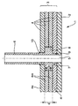
- the total designated 1, but only in the drawing plate reactor shown partially and in section from a stack of plates 2, which are covered by a total of 3 designated end plate is completed.
- the end plate 3 in The exemplary embodiment shown consists of four partial plates 4. At the one shown in the drawing plate 2 close any number of other plates.
- the stack will be on the End plate 3 opposite side by another, likewise End plate, not shown, completed. This can it is a conventional end plate or one as well end plate constructed of several partial plates.
- the number of Sub-plates 3 is in both the end plate 3 and opposite end plate freely selectable.
- Plate reactors are generally known from the prior art and are therefore only briefly and as far as for the Understanding of the invention necessarily described. Under plate reactors In the sense used here, devices for Implementation of chemical reactions, devices for transmission of thermal energy between different media, but also understood combinations of them.
- the plates 2 are wells, rooms or not shown in the drawing Media channels are provided. In the following it becomes Simplification only spoken of channels. It can be both identical plates 2 and different for the media used Plates 2 are used. The individual plates 2 can flow through the media serially and / or in parallel become.
- suitable in the channels Catalyst materials in any form - for example as Filling, coating etc. - to support the chemical Reaction to be provided.
- distributor or Collective channels 5 are provided. These are preferred through holes in the individual plates 2 and formed in the end plate 3, which during assembly in The direction of the stack should lie congruently one above the other. Only one such distribution channel 5 is shown in the drawing shown. With a complete plate reactor 1, however one or more distributors each Collection channels 5 are provided.
- a feed line 6 projects into the distribution channel 5, which for the supply of a medium gas-tight with the distribution channel 5 is connected.
- the Feed line 6 shown as a circular tube which is also a represents preferred embodiment.
- the feed line 6 has an annular collar 8 on its outer circumference 7.
- the two middle partial plates 4m have one enlarged bore, the diameter of which essentially Outer diameter of the collar 8 corresponds.
- the thickness d of the two middle part plates 4m corresponds essentially to the axial width b of the collar 8 the thickness d of the two middle part plates 4m.
- the partial plates 4 all have in the preferred embodiment same thicknesses, which also corresponds to the thickness of the plates 2.
- thick partial plates 4 in which case the axial width b of the collar 8 of the thickness d of those Corresponds to plates with enlarged bore.
- the diameter of the bores preferably corresponds to Sub-plates 4 essentially the outside diameter of the feed line 6, while the diameter of the holes in the plates 2 essentially corresponds to the inside diameter of the feed line 6.
- the axial position of the collar 8 is preferably chosen so that the axial end 9th the supply line 6 after assembly with that of the plate 2 facing edge of the end plate 3 completes. This means that the axial distance of the collar 8 from the axial end 9 of the Feed line 6 substantially equal to the thickness of the innermost one Partial plate 4i is. This prevents the feed line 6 affects the supply of the channels in the plate 2 or even disabled.
- the plates 2 In the manufacture of the plate reactor 1, the plates 2 stacked on top of each other and then the innermost panel 4i placed on top of this stack. Then the feed line 6 inserted in the distribution channel 5, the collar 8 rests on the surface of the innermost partial plate 4i. Subsequently the two middle slabs are 4m above the Feed line 6 slipped. Due to the matching dimensioning of the two middle part plates 4m and the ring collar 8 form the surface of the top plate 4m and the upper edge of the collar 8 a substantially flat surface. Then the outermost partial plate 4a also placed over the feed line 6.
- solder material can also be used between the partial plates 4 or directly at the joints between feed line 6 with collar 8 and Bores of the partial plates 4 are provided.
- the arrangement of the collar 8 are essentially achieved two advantages. Firstly, the joint surface between Feed line 6 with collar 8 and the holes in the sub-plates 4 increased so that both the mechanical stability the tightness is also improved. On the other hand, the Feed line 6 in both the axial and radial Directions fixed so that no errors in the manufacture positioning can occur. In the event that the relationship The discharge line 6 is not rotationally symmetrical and therefore it depends on the direction of rotation, instead of normal continuous collar 8 of the outer circumference of the way Drain line 6 only partially with one Bund be provided, then in turn in the partial plates 4 a corresponding opening must be made. In principle, here is every form of a survey and the associated one Breakthrough possible, however, if possible easy manufacture is important.
- Annular collar 8 can be on feed line 6, for example small puncture should be provided, then in the a wire or snap ring is inserted.
- the invention relates generally to a plate reactor in which at least one of the supply and / or discharge lines 6 with the described attachment is provided regardless of whether still further supply and / or discharge lines 6 with conventional ones Attachment are provided.
Landscapes
- Engineering & Computer Science (AREA)
- Physics & Mathematics (AREA)
- Thermal Sciences (AREA)
- Mechanical Engineering (AREA)
- General Engineering & Computer Science (AREA)
- Devices And Processes Conducted In The Presence Of Fluids And Solid Particles (AREA)
- Physical Or Chemical Processes And Apparatus (AREA)
Abstract
Description
Claims (7)
- Plattenreaktor mit einem von Endplatten begrenzten Stapel von Platten zur Ausbildung von Reaktions- und/oder Wärmetauscherräumen, mit sich im wesentlichen in Stapelrichtung durch die Endplatten beziehungsweise Platten erstreckende und durch Durchbrechungen gebildete Verteiler- und/oder Sammelkanäle und mit einer Zu- beziehungsweise Abführleitung, die mit den Verteiler- beziehungsweise Sammelkanälen in Strömungsverbindung stehen, wobei die Zu- beziehungsweise Abführleitung teilweise in den Verteiler- beziehungsweise Sammelkanal gesteckt werden, wobei der Außendurchmesser der Zu- beziehungsweise Abführleitung im wesentlichen dem Innendurchmesser des Verteiler- beziehungsweise Sammelkanals entspricht und wobei die Zu- beziehungsweise Abführleitung gasdicht mit dem Verteiler- beziehungsweise Sammelkanal verbunden werden,
dadurch gekennzeichnet,
daß die Zu- beziehungsweise Abführleitung (6) an ihrem Außenumfang zumindest eine Erhebung (8) aufweist, daß die Enplatte (3) aus mehreren Teilplatten (4) gebildet ist und daß zumindest eine von der äußersten Teilplatte (4a) abweichende Teilplatte (4m) eine zu der zumindest einen Erhebung (8) korrespondierente Durchbrechung aufweist. - Plattenreaktor nach Anspruch 1,
dadurch gekennzeichnet,
daß die Zu- beziehungsweise Abführleitung (6) und der Verteiler- beziehungsweise Sammelkanal (5) zylinderförmig ausgebildet sind und daß die Durchbrechung in der zumindest einen zugehörigen Teilplatte (4m) durch eine Bohrung gebildet ist, deren Durchmesser im wesentlichem dem Außendruchmesser der Erhebung (8) entspricht. - Plattenreaktor nach Anspruch 1,
dadurch gekennzeichnet,
daß die Breite (b) der Erhebung (8) in Richtung der Längsächse der Zu- beziehungsweise Abführleitung (6) im wesentlichen der Dicke (d) einer oder mehrerer Teilplatten (4m) entspricht. - Plattenreaktor nach Anspruch 1,
dadurch gekennzeichnet,
daß vier Teilplatten (4) vorgesehen sind, wobei die beiden mittleren Teilplatten (4m) einen vergrößerten Durchmesser aufweisen, und wobei die Erhebung (8) derart an der Zubeziehungsweise Abführleitung (6) angeordnet ist, daß im zusammengebauten Zustand die Zu- beziehungsweise Abführleitung (6) sich lediglich bis in den Bereich der vierten Teilplatte (4i) ersteckt. - Plattenreaktor nach Anspruch 1,
dadurch gekennzeichnet,
daß die zumindest eine Erhebung (8) ein Ringbund ist - Plattenreaktor nach Anspruch 1,
dadurch gekennzeichnet,
daß die zumindest eine Erhebung (8) ein Draht- oder Sprengring ist, der in einen zugehörigen Einstich am Außenumfang der Zuführleitung (6) eingelegt ist. - Plattenreaktor nach Anspruch 1,
dadurch gekennzeichnet,
daß die zumindest eine Erhebung (8) durch Aufweiten der Zuführleitung (6) nach außen gebildet wird.
Applications Claiming Priority (2)
| Application Number | Priority Date | Filing Date | Title |
|---|---|---|---|
| DE19927924 | 1999-06-18 | ||
| DE19927924A DE19927924C1 (de) | 1999-06-18 | 1999-06-18 | Plattenreaktor |
Publications (3)
| Publication Number | Publication Date |
|---|---|
| EP1061321A2 true EP1061321A2 (de) | 2000-12-20 |
| EP1061321A3 EP1061321A3 (de) | 2001-01-17 |
| EP1061321B1 EP1061321B1 (de) | 2003-11-05 |
Family
ID=7911727
Family Applications (1)
| Application Number | Title | Priority Date | Filing Date |
|---|---|---|---|
| EP00106520A Expired - Lifetime EP1061321B1 (de) | 1999-06-18 | 2000-03-25 | Plattenreaktor |
Country Status (2)
| Country | Link |
|---|---|
| EP (1) | EP1061321B1 (de) |
| DE (2) | DE19927924C1 (de) |
Families Citing this family (1)
| Publication number | Priority date | Publication date | Assignee | Title |
|---|---|---|---|---|
| FR2988169B1 (fr) * | 2012-03-19 | 2014-04-18 | Dana Canada Corp | Ensemble raccord brase |
Citations (1)
| Publication number | Priority date | Publication date | Assignee | Title |
|---|---|---|---|---|
| DE3613596A1 (de) | 1986-04-22 | 1987-11-12 | Christian Dipl Ing Schneider | Waermeaustauscher und verfahren zu seiner herstellung |
Family Cites Families (3)
| Publication number | Priority date | Publication date | Assignee | Title |
|---|---|---|---|---|
| SE8501599D0 (sv) * | 1985-04-01 | 1985-04-01 | Torell Ab | Anordning vid en plattvermevexlare |
| US4872578A (en) * | 1988-06-20 | 1989-10-10 | Itt Standard Of Itt Corporation | Plate type heat exchanger |
| EP0702201A1 (de) * | 1994-09-14 | 1996-03-20 | General Motors Corporation | Gewalzter Wärmetauscherkern mit innen-mündender Zufuhrleitung |
-
1999
- 1999-06-18 DE DE19927924A patent/DE19927924C1/de not_active Expired - Fee Related
-
2000
- 2000-03-25 DE DE50004299T patent/DE50004299D1/de not_active Expired - Lifetime
- 2000-03-25 EP EP00106520A patent/EP1061321B1/de not_active Expired - Lifetime
Patent Citations (1)
| Publication number | Priority date | Publication date | Assignee | Title |
|---|---|---|---|---|
| DE3613596A1 (de) | 1986-04-22 | 1987-11-12 | Christian Dipl Ing Schneider | Waermeaustauscher und verfahren zu seiner herstellung |
Also Published As
| Publication number | Publication date |
|---|---|
| EP1061321A3 (de) | 2001-01-17 |
| DE19927924C1 (de) | 2000-09-07 |
| EP1061321B1 (de) | 2003-11-05 |
| DE50004299D1 (de) | 2003-12-11 |
Similar Documents
| Publication | Publication Date | Title |
|---|---|---|
| DE4340378C2 (de) | Wärmeaustauscher und Verfahren zur Herstellung derselben | |
| DE69106354T2 (de) | Gelöteter wärmeplattentauscher. | |
| DE69003404T3 (de) | Mehrrohrtypwärmetauscher. | |
| DE3908266A1 (de) | Waermeaustauscher und verfahren zur fluessigkeitsdichten befestigung einer bodenplatte an einem waermetauschernetz | |
| DE2657307A1 (de) | Rohrbuendel fuer einen waermetauscher | |
| DE2951352C2 (de) | Flachrohr-Wärmetauscher | |
| DE2903067A1 (de) | Lochplattenverkleidung des wasserbehaelters eines roehrenwaermetauschers | |
| CH629586A5 (de) | Waermeuebertrager. | |
| DE2555814C2 (de) | Flammrohrwand | |
| WO2017178120A1 (de) | Gewickelter wärmeübertrager | |
| DE2706049C2 (de) | Vorrichtung zum Lagern einer Vielzahl von Röhren in einem Wärmeaustauscher | |
| DE2240349B2 (de) | Stuetzkonstruktion fuer waermetauscherrohre | |
| WO2016131787A1 (de) | Rohrbündelwärmeübertrager mit sequentiell angeordneten rohrbündelkomponenten | |
| DE2804113A1 (de) | Halterung zur befestigung der rohre eines waermetauschers | |
| DE19927924C1 (de) | Plattenreaktor | |
| DE2210743A1 (de) | Wärmetauscher | |
| DD144601A5 (de) | Waermeaustauscher | |
| DE69715919T2 (de) | Plattenwärmetauscher | |
| EP0853224B1 (de) | Wärmeüberträger | |
| DE1501657B1 (de) | Brennstoffbeheizter thermionischer Konverter | |
| DE2822743C2 (de) | ||
| DE3440272A1 (de) | Verfahren zum herstellen eines stuetzteils fuer flachheizkoerper | |
| EP0026271A2 (de) | Wärmeübertrager, insbesondere für gas- oder ölbeheizte Wassererhitzer | |
| DE3313422A1 (de) | Rohr mit einer mehrzahl in die rohrwandung eingebrachter verformungsstellen zum einsatz in waermetauschern | |
| DE3138621A1 (de) | Waermeaustauscher |
Legal Events
| Date | Code | Title | Description |
|---|---|---|---|
| PUAI | Public reference made under article 153(3) epc to a published international application that has entered the european phase |
Free format text: ORIGINAL CODE: 0009012 |
|
| PUAL | Search report despatched |
Free format text: ORIGINAL CODE: 0009013 |
|
| AK | Designated contracting states |
Kind code of ref document: A2 Designated state(s): DE FR GB IT |
|
| AX | Request for extension of the european patent |
Free format text: AL;LT;LV;MK;RO;SI |
|
| AK | Designated contracting states |
Kind code of ref document: A3 Designated state(s): AT BE CH CY DE DK ES FI FR GB GR IE IT LI LU MC NL PT SE |
|
| AX | Request for extension of the european patent |
Free format text: AL;LT;LV;MK;RO;SI |
|
| 17P | Request for examination filed |
Effective date: 20001215 |
|
| AKX | Designation fees paid |
Free format text: DE FR GB IT |
|
| RAP1 | Party data changed (applicant data changed or rights of an application transferred) |
Owner name: BALLARD POWER SYSTEMS AG |
|
| 17Q | First examination report despatched |
Effective date: 20020906 |
|
| GRAH | Despatch of communication of intention to grant a patent |
Free format text: ORIGINAL CODE: EPIDOS IGRA |
|
| GRAS | Grant fee paid |
Free format text: ORIGINAL CODE: EPIDOSNIGR3 |
|
| GRAA | (expected) grant |
Free format text: ORIGINAL CODE: 0009210 |
|
| AK | Designated contracting states |
Kind code of ref document: B1 Designated state(s): DE FR GB IT |
|
| PG25 | Lapsed in a contracting state [announced via postgrant information from national office to epo] |
Ref country code: IT Free format text: LAPSE BECAUSE OF FAILURE TO SUBMIT A TRANSLATION OF THE DESCRIPTION OR TO PAY THE FEE WITHIN THE PRESCRIBED TIME-LIMIT;WARNING: LAPSES OF ITALIAN PATENTS WITH EFFECTIVE DATE BEFORE 2007 MAY HAVE OCCURRED AT ANY TIME BEFORE 2007. THE CORRECT EFFECTIVE DATE MAY BE DIFFERENT FROM THE ONE RECORDED. Effective date: 20031105 Ref country code: FR Free format text: LAPSE BECAUSE OF FAILURE TO SUBMIT A TRANSLATION OF THE DESCRIPTION OR TO PAY THE FEE WITHIN THE PRESCRIBED TIME-LIMIT Effective date: 20031105 |
|
| REG | Reference to a national code |
Ref country code: GB Ref legal event code: FG4D Free format text: NOT ENGLISH |
|
| REF | Corresponds to: |
Ref document number: 50004299 Country of ref document: DE Date of ref document: 20031211 Kind code of ref document: P |
|
| GBT | Gb: translation of ep patent filed (gb section 77(6)(a)/1977) |
Effective date: 20040209 |
|
| PLBE | No opposition filed within time limit |
Free format text: ORIGINAL CODE: 0009261 |
|
| STAA | Information on the status of an ep patent application or granted ep patent |
Free format text: STATUS: NO OPPOSITION FILED WITHIN TIME LIMIT |
|
| 26N | No opposition filed |
Effective date: 20040806 |
|
| EN | Fr: translation not filed | ||
| PGFP | Annual fee paid to national office [announced via postgrant information from national office to epo] |
Ref country code: GB Payment date: 20100322 Year of fee payment: 11 |
|
| PGFP | Annual fee paid to national office [announced via postgrant information from national office to epo] |
Ref country code: DE Payment date: 20100419 Year of fee payment: 11 |
|
| GBPC | Gb: european patent ceased through non-payment of renewal fee |
Effective date: 20110325 |
|
| PG25 | Lapsed in a contracting state [announced via postgrant information from national office to epo] |
Ref country code: DE Free format text: LAPSE BECAUSE OF NON-PAYMENT OF DUE FEES Effective date: 20111001 |
|
| REG | Reference to a national code |
Ref country code: DE Ref legal event code: R119 Ref document number: 50004299 Country of ref document: DE Effective date: 20111001 |
|
| PG25 | Lapsed in a contracting state [announced via postgrant information from national office to epo] |
Ref country code: GB Free format text: LAPSE BECAUSE OF NON-PAYMENT OF DUE FEES Effective date: 20110325 |