EP1060957A2 - Airbag module unit, and airbag module - Google Patents
Airbag module unit, and airbag module Download PDFInfo
- Publication number
- EP1060957A2 EP1060957A2 EP00111938A EP00111938A EP1060957A2 EP 1060957 A2 EP1060957 A2 EP 1060957A2 EP 00111938 A EP00111938 A EP 00111938A EP 00111938 A EP00111938 A EP 00111938A EP 1060957 A2 EP1060957 A2 EP 1060957A2
- Authority
- EP
- European Patent Office
- Prior art keywords
- gas generator
- tabs
- gas bag
- edge
- cover cap
- Prior art date
- Legal status (The legal status is an assumption and is not a legal conclusion. Google has not performed a legal analysis and makes no representation as to the accuracy of the status listed.)
- Granted
Links
- 239000002184 metal Substances 0.000 claims description 16
- 230000002093 peripheral effect Effects 0.000 claims description 7
- 239000000463 material Substances 0.000 claims description 6
- 238000004519 manufacturing process Methods 0.000 claims description 5
- 238000005452 bending Methods 0.000 claims description 4
- 238000005266 casting Methods 0.000 claims description 4
- 230000003313 weakening effect Effects 0.000 claims description 4
- 238000007664 blowing Methods 0.000 claims description 3
- 238000002347 injection Methods 0.000 claims description 2
- 239000007924 injection Substances 0.000 claims description 2
- 238000010276 construction Methods 0.000 abstract 1
- 238000004382 potting Methods 0.000 description 2
- 238000003466 welding Methods 0.000 description 2
- 239000000853 adhesive Substances 0.000 description 1
- 230000001070 adhesive effect Effects 0.000 description 1
- 230000005540 biological transmission Effects 0.000 description 1
- 230000000295 complement effect Effects 0.000 description 1
- 238000005516 engineering process Methods 0.000 description 1
- 238000001746 injection moulding Methods 0.000 description 1
- 238000003780 insertion Methods 0.000 description 1
- 230000037431 insertion Effects 0.000 description 1
- 238000009434 installation Methods 0.000 description 1
- 239000007788 liquid Substances 0.000 description 1
- 238000005507 spraying Methods 0.000 description 1
- 230000007704 transition Effects 0.000 description 1
Images


Classifications
-
- B—PERFORMING OPERATIONS; TRANSPORTING
- B60—VEHICLES IN GENERAL
- B60R—VEHICLES, VEHICLE FITTINGS, OR VEHICLE PARTS, NOT OTHERWISE PROVIDED FOR
- B60R21/00—Arrangements or fittings on vehicles for protecting or preventing injuries to occupants or pedestrians in case of accidents or other traffic risks
- B60R21/02—Occupant safety arrangements or fittings, e.g. crash pads
- B60R21/16—Inflatable occupant restraints or confinements designed to inflate upon impact or impending impact, e.g. air bags
- B60R21/20—Arrangements for storing inflatable members in their non-use or deflated condition; Arrangement or mounting of air bag modules or components
- B60R21/217—Inflation fluid source retainers, e.g. reaction canisters; Connection of bags, covers, diffusers or inflation fluid sources therewith or together
Definitions
- the invention relates to a structural unit for an airbag module, in particular a steering wheel gas bag module consisting of a gas generator carrier and a cover cap.
- the invention also relates to an airbag module with a assembly according to the invention and a gas generator and a Gas bag.
- the cover cap of a steering wheel gas bag module is usually made of Plastic and is on the front when the module is installed visible.
- the gas generator and gas bag are placed on the back of the container Cover cap inserted.
- a so-called gas generator carrier Sheet metal is attached to the cover cap using rivets or hooks and forms the after inserting the gas bag and gas generator closing back of the cover cap.
- On this gas generator carrier the gas generator is attached and the entire module is over attached this carrier to the steering wheel. It is therefore understood that the Gas generator support must be very stable and the connection Withstand high tensile forces between the gas generator carrier and the cover cap got to. When opening the cover cap by the unfolding This is because the gas bag will exert high forces on the cover cap and thus on it the connection between cover cap and gas generator carrier is exercised.
- the invention creates a simple and stable structural unit for a Airbag module, in particular a steering wheel airbag module, which itself also thanks to a small installation space and a high power transmission Characterized connection between gas generator carrier and cover cap.
- a unit of the type mentioned achieved that the gas generator carrier from a stamped and formed
- the tabs has, which can be folded inwards and towards each other to one receiving space limited by the cover cap and the gas generator support for the gas bag to close on the back.
- the unit is not an additional part such as rivets or on the gas generator support molded hooks required. Rather, the gas generator carrier itself integrated into the cover cap, i.e. in them positively embedded.
- An optimal embedding of the sheet metal section in the cap can be achieved in that the sheet metal section Has recesses or projections, which are penetrated by the cover cap become.
- the folded tabs form in the fully assembled state together with other parts of the gas bag module a stable mounting base.
- the sheet metal section is preferably used for casting or Injection molding manufacture of the cover cap in a form-fitting manner involved.
- the liquid plastic can then really do everything Fill in the recesses in the gas generator support.
- the tabs can be folded around at right angles around bending lines, along which a material weakening in the sheet metal section, e.g. a Perforation.
- the stability of the entire housing can be increased that the sheet metal section has an edge area that is caused by folding or the like is formed into a peripheral edge.
- the sheet metal section can be embedded in the cover cap around the peripheral edge his. This edge area also preferably has the cutouts for the positive engagement of the plastic material.
- the sheet metal section has according to the preferred embodiment several foldable flaps, preferably on the peripheral edge are arranged in pairs opposite to each other.
- the tabs each have at least one outwardly projecting mounting flange.
- the tabs can be fasteners wear, by means of which the gas bag module is locked to the vehicle.
- Fastening devices are, for example, so-called snap bolts, Press nuts or the like possible on the Tabs are attached. Other fasteners are also very easy to integrate into the tabs.
- the tabs also have a plastic border on their free edge, which makes it easier to clamp this free edge.
- the free one The edge with the plastic border can also be the Stroke contact, the exact positioning of the gas generator in axial direction so that it protrudes out of the module or serve to guide the gas bag module.
- the plastic enclosure leaves a complicated shape too.
- these sections form a floor area which has a recess for the arrangement of the gas generator and has openings for connecting screws.
- the Gas generator can go out of the housing of the housing via this recess Stand out of the gas bag module.
- the openings for the connecting screws allow the gas generator and a gas bag retaining plate to be locked on the gas generator support. All individual parts become one Airbag module connected, where the edge of the airbag blowing opening between the gas bag holding plate and the free edge of the tabs is clamped.
- the invention also relates to an airbag module with a assembly according to the invention, in which the tabs after folding by 90 ° form sections of a floor area which has a recess for the arrangement of the gas generator and openings for connecting screws having.
- an airbag holding plate becomes and the flange of the gas generator with the gas generator carrier connected to an airbag module.
- the edge of the air opening of the gas bag is between the gas bag holding plate and the free edge of the Clamps clamped.
- the gas bag module according to the invention stands out through a simple and stable connection of the gas bag holding plate with Gas generator and gas generator support.
- the Straps securely attached to the cover cap.
- the gas generator is preferred directly attached to the tabs, i.e. without liner other parts.
- the gas generator, straps and holding plate complement each other each other to create a stable base.
- FIG. 1 shows an airbag module in the right half, which among other things has the following parts: a structural unit for the gas bag module, consisting of a gas generator carrier 1, through a stamped and formed sheet metal section is formed, and consisting of a cup-shaped cap 3.
- a structural unit for the gas bag module consisting of a gas generator carrier 1, through a stamped and formed sheet metal section is formed, and consisting of a cup-shaped cap 3.
- the gas bag module is a folded one housed in the cap 3 Airbag 5 on, the edge 7 of the so-called blowing opening of the Gas bag 5 gas bag holding plate 9 surrounding the inside and a large part gas generator 11 protruding into the interior of the cap 3.
- the covering cap 3 is a so-called two-component covering cap, with a haptically and visually appealing outer layer 13 and one hard inner carrier layer 15.
- the layer 15 has a Front wall 17 and a circumferential side wall 19.
- In the side wall 19 is an edge in the production of the cover 3 by casting 21 of the gas generator support 1 embedded or embedded.
- the edge 21 is overmolded or foamed, whereby not only one adhesive, but also a positive connection between the Gas generator carrier 1 and the layer 15 of the cap 3 results.
- the gas generator support 1 has numerous cutouts 23 in the edge 21, which can be clearly seen in FIG. 3.
- the cap 1 thus penetrates plastic into the recesses 23, so that there is a positive connection between cover cap 3 and gas generator support 1 results.
- the gas generator support 1 is made from a stamped sheet metal section made by forming.
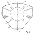
- Edge 21 already explained is formed by folding the edge area of the sheet metal section. So that the edge 21 also runs completely (see FIG. 2), it can be necessary to fold sections together e.g. by spot welding or by potting with plastic, the one above the other Recesses 23 penetrates to connect. Spot welding is in Figure 2 at the point labeled 25 and the potting indicated by means of plastic in Figure 6 at the point designated 69.
- the edge has on its numerous, spaced-apart recesses 23 over the entire circumference on.
- On opposite sides of the edge 21 there are two tabs 27 integrally formed on the edge 21.
- the transition area or material weakening 29 is provided, which is a hinge defined for bending the tabs 27.
- Form the two tabs 27 each half of a bottom area of the housing of the gas bag module, which consists of the cup-shaped cover cap 3 and the gas generator support 1 is formed. Through the tabs 27, the housing be closed, the tabs the bottom area of the housing form.
- the tabs 27 have recesses 31 which are the locking of the Gas generator 11 serve.
- 27 is on each tab formed at about 45 ° outwardly projecting mounting flange 33.
- the mounting flange 33 is formed by a surface of a roof local deformation 35 formed in each tab 27. That through the Forming resulting recess 37 can accommodate a Screw head or a nut welded to the mounting flange 33 39 serve. With 41 is a through opening in the mounting flange 33 designated.
- the gas generator carrier 1 is characterized by simple manufacture and a high stability, because the edge 21 is circumferential and closed so that it forms a kind of frame.
- Each tab 27 has a semicircular, large recess 41 which turns into one when both tabs 27 are folded inwards complete circular recess. The tabs are so far folded over that they are essentially in one plane Form the assembly base. Each tab has in the area of the recesses 41 a free edge 43. When spraying the cap 3 is to the free edge 43 of each tab 27 a so-called plastic enclosure 45 molded, which in Figure 1 in the left half particularly well see is.
- the two tabs 27 are like shown in Figure 1, left, downwards in front, so that the cover cap 3 is completely open.
- the gas bag 5 is then placed in the cover cap 3 inserted with the gas bag holding plate 9 therein, wherein several connecting screws 47, the head of which is inside the gas bag is already inserted and through openings in the gas bag holding plate 9 and 5 protrude in the gas bag.
- the tabs 27 um Folded 90 ° inwards so that the connecting screws 47 through the Open openings 31.
- a flange 51 projecting radially from its housing on the tabs 27 is present.
- the gas generator 11 is thus without the insertion of an intermediate part directly attached to the gas generator support.
- the Flange 51 has openings, not shown, through which the connecting screws 47 can extend.
- Nuts 53 are finally on screwed on the shaft ends of the connecting screws 47.
- the edge 7 of the gas bag, the edge 43 of the Tabs 27 with the plastic bezel 45 and the flange 51 together clamped.
- This gas bag module is attached to the vehicle by Screws which are screwed into the nuts 39 through the openings 41 can be.
- Screws which are screwed into the nuts 39 through the openings 41 can be.
- Screws which are screwed into the nuts 39 through the openings 41 can be.
- FIG. 1 Screw 5 and a section V of the vehicle-side steering wheel structure shown.
- the 45 ° projecting mounting flanges allow easy Screw the gas bag module diagonally from the back of the hub of the Steering wheel off, which makes it easy to access for assembly results.
- the covering cap 3 When the gas bag is unfolded, the covering cap 3 is on the front torn open so that the gas bag can reach the occupants can.
- the brought in when opening the cap 3 in this high forces are generated by the stable connection to the gas generator carrier 1 introduced into the steering wheel.
- a break in the connection between cap 3 and gas generator support 1 can by Embedding of the gas generator carrier 1 in the cap 3 avoided become.
- tabs 27 are provided which, after being folded over by 90 ° Form the bottom area of the module.
- the tabs 27 close circumferentially to each other.
- peripheral edge 21 is transverse to the direction of rotation, i.e. several in the axial direction of the gas generator has successively arranged recesses 23. It is more precise said three rows of consecutive recesses are provided the individual recesses of adjacent rows being offset from one another are. The edge 21 thereby receives a deformable area, in which the stability of the edge is deliberately reduced.
Landscapes
- Engineering & Computer Science (AREA)
- Mechanical Engineering (AREA)
- Air Bags (AREA)
Abstract
Description
Die Erfindung betrifft eine Baueinheit für ein Gassack-Modul, insbesondere ein Lenkrad-Gassack-Modul, bestehend aus einem Gasgeneratorträger und einer Abdeckkappe.The invention relates to a structural unit for an airbag module, in particular a steering wheel gas bag module consisting of a gas generator carrier and a cover cap.
Die Erfindung betrifft darüber hinaus ein Gassack-Modul mit einer erfindungsgemäßen Baueinheit sowie einem Gasgenerator und einem Gassack.The invention also relates to an airbag module with a assembly according to the invention and a gas generator and a Gas bag.
Die Abdeckkappe eines Lenkrad-Gassack-Moduls ist üblicherweise aus Kunststoff und ist im eingebauten Zustand des Moduls vorderseitig sichtbar. Gasgenerator und Gassack werden rückseitig in die behälterförmige Abdeckkappe eingesetzt. Ein sogenannter Gasgeneratorträger aus Blech wird an der Abdeckkappe mittels Nieten oder Haken befestigt und bildet die nach dem Einsetzen von Gassack und Gasgenerator zu schließende Rückseite der Abdeckkappe. An diesem Gasgeneratorträger wird der Gasgenerator befestigt, und das gesamte Modul wird über diesen Träger am Lenkrad angebracht. Es versteht sich deshalb, daß der Gasgeneratorträger sehr stabil ausgebildet sein muß und die Verbindung zwischen Gasgeneratorträger und Abdeckkappe hohen Zugkräften standhalten muß. Beim Öffnen der Abdeckkappe durch den sich entfaltenden Gassack werden nämlich hohe Kräfte auf die Abdeckkappe und damit auf die Verbindung zwischen Abdeckkappe und Gasgeneratorträger ausgeübt. Die bisherigen Verbindungen von Gasgeneratorträger und Abdeckkappe, nämlich Nieten und Haken, führten zu hohen Lochleibungsdrücken in den Nieten- oder Hakenfenstern. Die Gefahr des Ausreißens der Kunststoffabdeckkappe wurde durch aufwendige Hinterschnitte zur Kraftaufnahme in der Kappe reduziert, die aber nur mittels aufwendiger Spritzwerkzeuge realisiert werden konnten. Zudem mußten die Nieten oder Haken möglichst weit entfernt vom Gassack und damit nahe an der Rückseite der Abdeckkappe platziert sein, damit ein Kontakt mit dem Gassack und ein Einreißen des Gassacks durch die Nieten vermieden wird. Das bedeutet aber, daß die Nieten sehr nahe am rückseitigen Rand der Abdeckkappe angebracht werden mußten, ggf. sogar zusätzlicher Bauraum benötigt wurde, um ein Ausreißen der Abdeckkappe auszuschließen. Die Verbindung von Abdeckkappe und Gasgeneratorträger mittels Nieten oder Umbiegen von Haken ist zudem sehr aufwendig.The cover cap of a steering wheel gas bag module is usually made of Plastic and is on the front when the module is installed visible. The gas generator and gas bag are placed on the back of the container Cover cap inserted. A so-called gas generator carrier Sheet metal is attached to the cover cap using rivets or hooks and forms the after inserting the gas bag and gas generator closing back of the cover cap. On this gas generator carrier the gas generator is attached and the entire module is over attached this carrier to the steering wheel. It is therefore understood that the Gas generator support must be very stable and the connection Withstand high tensile forces between the gas generator carrier and the cover cap got to. When opening the cover cap by the unfolding This is because the gas bag will exert high forces on the cover cap and thus on it the connection between cover cap and gas generator carrier is exercised. The previous connections of gas generator carrier and cover cap, namely rivets and hooks, led to high embrasure pressures in the Rivet or hook windows. The danger of the plastic cover cap tearing out was made by using complex undercuts to absorb the force the cap is reduced, but only by means of complex injection tools could be realized. In addition, the rivets or hooks had to as far away from the gas bag as possible and thus close to the back the cap must be placed so that there is contact with the gas bag and tearing of the gas bag by the rivets is avoided. The but means that the rivets very close to the back edge of the Cover cap had to be attached, possibly even additional space was needed to prevent the cover from tearing out. The Connection of cover cap and gas generator support by means of rivets or Bending hooks is also very complex.
Die Erfindung schafft eine einfache und stabile Baueinheit für ein Gassack-Modul, insbesondere ein Lenkrad-Gassack-Modul, welches sich zudem auch durch einen geringen Bauraum und eine hohe Kräfte übertragende Verbindung zwischen Gasgeneratorträger und Abdeckkappe auszeichnet. Dies wird bei einer Baueinheit der eingangs genannten Art dadurch erreicht, daß der Gasgeneratorträger aus einem ausgestanzten und umgeformten Blechabschnitt besteht, der randseitig formschlüssig in die aus Kunststoff bestehende Abdeckkappe eingebunden ist und der Laschen aufweist, die einwärts und aufeinander zu umklappbar sind, um einen durch die Abdeckkappe und den Gasgeneratorträger begrenzten Aufnahmeraum für den Gassack rückseitig zu schließen. Bei der erfindungsgemäßen Baueinheit sind keine zusätzlichen Teile wie Nieten oder am Gasgeneratorträger angeformte Haken erforderlich. Vielmehr ist der Gasgeneratorträger selbst in die Abdeckkappe eingebunden, d.h. in sie formschlüssig eingebettet. Eine optimale Einbettung des Blechabschnitts in die Abdeckkappe kann dadurch erreicht werden, daß der Blechabschnitt Ausnehmungen oder Vorsprünge hat, die von der Abdeckkappe durchdrungen werden. Die umgeklappten Laschen bilden in fertig montiertem Zustand zusammen mit anderen Teilen des Gassack-Moduls eine stabile Montagebasis. The invention creates a simple and stable structural unit for a Airbag module, in particular a steering wheel airbag module, which itself also thanks to a small installation space and a high power transmission Characterized connection between gas generator carrier and cover cap. This is in a unit of the type mentioned achieved that the gas generator carrier from a stamped and formed There is a sheet metal section that fits positively into the edge plastic cover cap is integrated and the tabs has, which can be folded inwards and towards each other to one receiving space limited by the cover cap and the gas generator support for the gas bag to close on the back. In the case of the invention The unit is not an additional part such as rivets or on the gas generator support molded hooks required. Rather, the gas generator carrier itself integrated into the cover cap, i.e. in them positively embedded. An optimal embedding of the sheet metal section in the cap can be achieved in that the sheet metal section Has recesses or projections, which are penetrated by the cover cap become. The folded tabs form in the fully assembled state together with other parts of the gas bag module a stable mounting base.
Vorzugsweise ist der Blechabschnitt bei der gießtechnischen oder spritzgießtechnischen Herstellung der Abdeckkappe formschlüssig in sie eingebunden. Der flüssige Kunststoff kann dann auch wirklich sämtliche Ausnehmungen im Gasgeneratorträger ausfüllen.The sheet metal section is preferably used for casting or Injection molding manufacture of the cover cap in a form-fitting manner involved. The liquid plastic can then really do everything Fill in the recesses in the gas generator support.
Die Laschen sind etwa rechtwinklig um Biegelinien umklappbar, längs derer im Blechabschnitt eine Materialschwächung, z.B. eine Perforation, ausgebildet ist.The tabs can be folded around at right angles around bending lines, along which a material weakening in the sheet metal section, e.g. a Perforation.
Die Stabilität des gesamten Gehäuses kann dadurch erhöht werden, daß der Blechabschnitt einen Randbereich aufweist, der durch Abkanten oder dergleichen zu einem umlaufenden Rand umgeformt ist. In diesem umlaufenden Rand kann der Blechabschnitt in die Abdeckkappe eingebettet sein. Dieser Randbereich weist auch vorzugsweise die Aussparungen für den formschlüssigen Eingriff des Kunststoffmaterials auf.The stability of the entire housing can be increased that the sheet metal section has an edge area that is caused by folding or the like is formed into a peripheral edge. In this The sheet metal section can be embedded in the cover cap around the peripheral edge his. This edge area also preferably has the cutouts for the positive engagement of the plastic material.
Der Blechabschnitt hat gemäß der bevorzugten Ausführungsform mehrere umklappbare Laschen, die am umlaufenden Rand vorzugsweise paarweise einander gegenüberliegend angeordnet sind.The sheet metal section has according to the preferred embodiment several foldable flaps, preferably on the peripheral edge are arranged in pairs opposite to each other.
Mit dem Umklappen der Laschen wird dann die Rückseite des durch die Abdeckkappe und den Gasgeneratorträger gebildeten Gehäuses des Gassack-Moduls geschlossen, nachdem Gassack mit Gassackhalteblech und eventuell auch Gasgenerator (je nach angestrebtem System) in die Abdeckkappe eingesetzt worden sind.When the flaps are folded down the back of the the cover cap and the gas generator support housing formed Gas bag module closed after gas bag with gas bag holding plate and possibly also gas generator (depending on the desired system) in the Cover cap have been inserted.
Eine platzsparende Möglichkeit der Befestigung der erfindungsgemäßen Baueinheit am Fahrzeug wird dadurch erreicht, daß die Laschen jeweils wenigstens einen nach außen vorstehenden Montageflansch aufweisen. Darüber hinaus können die Laschen Befestigungseinrichtungen tragen, mittels denen das Gassackmodul am Fahrzeug arretiert wird. Als Befestigungseinrichtungen sind hier zum Beispiel sogenannte Einschnappbolzen, Einpressmuttern oder dergleichen möglich, die an den Laschen angebracht sind. Auch andere Befestigungseinrichtungen sind sehr einfach in die Laschen integrierbar.A space-saving way of attaching the invention Unit on the vehicle is achieved in that the tabs each have at least one outwardly projecting mounting flange. In addition, the tabs can be fasteners wear, by means of which the gas bag module is locked to the vehicle. As Fastening devices are, for example, so-called snap bolts, Press nuts or the like possible on the Tabs are attached. Other fasteners are also very easy to integrate into the tabs.
An ihrem freien Rand haben die Laschen zudem eine Kunststoffeinfassung, die ein Klemmen dieses freien Randes erleichtert. Der freie Rand mit der Kunststoffeinfassung kann darüber hinaus der Hubkontaktaufnahme, der exakten Positionierung des Gasgenerators in axialer Richtung, damit er definiert aus dem Modul heraussteht oder der Führung des Gassackmoduls dienen. Die Kunststoffumfassung läßt eine komplizierte Formgebung zu.The tabs also have a plastic border on their free edge, which makes it easier to clamp this free edge. The free one The edge with the plastic border can also be the Stroke contact, the exact positioning of the gas generator in axial direction so that it protrudes out of the module or serve to guide the gas bag module. The plastic enclosure leaves a complicated shape too.
Nach dem Umklappen der Laschen um etwa 90° bilden diese Abschnitte eines Bodenbereichs, der eine Ausnehmung für die Anordnung des Gasgenerators sowie Öffnungen für Verbindungsschrauben aufweist. Der Gasgenerator kann über diese Ausnehmung nach außen aus dem Gehäuse des Gassack-Moduls herausragen. Die Öffnungen für die Verbindungsschrauben erlauben das Arretieren des Gasgenerators und eines Gassackhalteblechs am Gasgeneratorträger. Damit werden sämtliche Einzelteile zu einem Gassack-Modul verbunden, bei dem der Rand der Einblasöffnung des Gassacks zwischen dem Gassackhalteblech und dem freien Rand der Laschen geklemmt ist.After the flaps have been folded over by about 90 °, these sections form a floor area which has a recess for the arrangement of the gas generator and has openings for connecting screws. The Gas generator can go out of the housing of the housing via this recess Stand out of the gas bag module. The openings for the connecting screws allow the gas generator and a gas bag retaining plate to be locked on the gas generator support. All individual parts become one Airbag module connected, where the edge of the airbag blowing opening between the gas bag holding plate and the free edge of the tabs is clamped.
Die Erfindung betrifft darüber hinaus ein Gassack-Modul mit einer erfindungsgemäßen Baueinheit, bei der die Laschen nach dem Umklappen um 90° Abschnitte eines Bodenbereichs bilden, der eine Ausnehmung für die Anordnung des Gasgenerators sowie Öffnungen für Verbindungsschrauben aufweist. Mittels der Verbindungsschrauben werden ein Gassackhalteblech und der Flansch des Gasgenerators mit dem Gasgeneratorträger zu einem Gassack-Modul verbunden. Der Rand der Einblasöffnung des Gassacks wird zwischen dem Gassackhalteblech und dem freien Rand der Laschen geklemmt. Das erfindungsgemäße Gassack-Modul zeichnet sich durch eine einfache und stabile Verbindung von Gassackhalteblech mit Gasgenerator und Gasgeneratorträger aus. Darüber hinaus sind die Laschen stabil an der Abdeckkappe befestigt. Der Gasgenerator ist vorzugsweise unmittelbar an den Laschen befestigt, d.h. ohne Zwischenlage anderer Teile. Gasgenerator, Laschen und Halteblech ergänzen sich gegenseitig zur Schaffung einer stabilen Basis.The invention also relates to an airbag module with a assembly according to the invention, in which the tabs after folding by 90 ° form sections of a floor area which has a recess for the arrangement of the gas generator and openings for connecting screws having. By means of the connecting screws, an airbag holding plate becomes and the flange of the gas generator with the gas generator carrier connected to an airbag module. The edge of the air opening of the gas bag is between the gas bag holding plate and the free edge of the Clamps clamped. The gas bag module according to the invention stands out through a simple and stable connection of the gas bag holding plate with Gas generator and gas generator support. In addition, the Straps securely attached to the cover cap. The gas generator is preferred directly attached to the tabs, i.e. without liner other parts. The gas generator, straps and holding plate complement each other each other to create a stable base.
Weitere Merkmale und Vorteile der Erfindung ergeben sich aus der nachfolgenden Beschreibung und aus den nachfolgenden Zeichnungen, auf die Bezug genommen wird. In den Zeichnungen zeigen:
- Figur 1 eine Querschnittsansicht durch eine Ausführungsform der erfindungsgemäßen Baueinheit, wobei die linke Hälfte die Baueinheit mit offener Lasche und die rechte Hälfte das gesamte Gassack-Modul mit erfindungsgemäßer Baueinheit, mit eingesetztem Gassack und Gasgenerator bei umgeklappter Lasche zeigt,
- Figur 2 eine verkleinerte Draufsicht des in die Abdeckkappe noch nicht eingebundenen Gasgeneratorträgers,
Figur 3 eine Schnittansicht des Gasgeneratorträgers nach der Linie III-III in Figur 2,- Figur 4 eine Seitenansicht des Gasgeneratorträgers,
Figur 5 eine Querschnittsansicht durch eine weitere Ausführungsform der erfindungsgemäßen Baueinheit, wobei hier auch wieder die linke Hälfte die Baueinheit mit offener Lasche und die rechte Hälfte das gesamte Gassack-Modul mit erfindungsgemäßer Baueinheit, mit eingesetztem Gassack und Gasgenerator bei umgeklappter Lasche zeigt,- Figur 6 eine Draufsicht des in die Abdeckkappe noch nicht
eingebundenen Gasgeneratorträgers, der in der Ausführungsform nach
Figur 5 dargestellt ist, und - Figur 7 eine Abwicklung des in Figur 6 dargestellten Gasgeneratorträgers noch vor dessen Weiterverarbeitung.
- FIG. 1 shows a cross-sectional view through an embodiment of the assembly according to the invention, the left half showing the assembly with the flap open and the right half the entire gas bag module with the assembly according to the invention, with the gas bag and gas generator inserted, with the flap folded down,
- FIG. 2 shows a reduced plan view of the gas generator carrier that has not yet been integrated into the cover cap,
- FIG. 3 shows a sectional view of the gas generator support along the line III-III in FIG. 2,
- FIG. 4 shows a side view of the gas generator carrier,
- FIG. 5 shows a cross-sectional view through a further embodiment of the assembly according to the invention, the left half again showing the assembly with the open flap and the right half showing the entire gas bag module with the assembly according to the invention, with the gas bag and gas generator inserted with the flap folded down,
- FIG. 6 shows a plan view of the gas generator carrier which has not yet been integrated into the cover cap and which is shown in the embodiment according to FIG. 5, and
- Figure 7 is a processing of the gas generator carrier shown in Figure 6 before its further processing.
In Figur 1 ist in der rechten Hälfte ein Gassack-Modul dargestellt,
das unter anderem folgende Teile aufweist: eine Baueinheit für
das Gassack-Modul, bestehend aus einem Gasgeneratorträger 1, der durch
einen ausgestanzten und umgeformten Blechabschnitt gebildet ist, und
bestehend aus einer topfförmigen Abdeckkappe 3. Darüber hinaus weist
das Gassack-Modul einen in der Abdeckkappe 3 untergebrachten, gefalteten
Gassack 5 auf, ein den Rand 7 der sogenannten Einblasöffnung des
Gassacks 5 innenseitig umgebendes Gassackhalteblech 9 und einen großteils
in das Innere der Abdeckkappe 3 hineinragenden Gasgenerator 11. 1 shows an airbag module in the right half,
which among other things has the following parts: a structural unit for
the gas bag module, consisting of a gas generator carrier 1, through
a stamped and formed sheet metal section is formed, and
consisting of a cup-
Die Abdeckkappe 3 ist eine sogenannte Zweikomponenten-Abdeckkappe,
mit einer haptisch und optisch ansprechenden Außenschicht 13 und einer
harten, innenseitigen Trägerschicht 15. Die Schicht 15 hat eine
Vorderwand 17 sowie eine umlaufende Seitenwand 19. In die Seitenwand
19 ist bei der gießtechnischen Herstellung der Abdeckkappe 3 ein Rand
21 des Gasgeneratorträgers 1 eingebunden oder eingebettet. Der Rand 21
wird dabei umspritzt oder umschäumt, wodurch sich nicht nur eine
adhäsive, sondern auch eine formschlüssige Verbindung zwischen dem
Gasgeneratorträger 1 und der Schicht 15 der Abdeckkappe 3 ergibt.The covering
Zur Schaffung einer optimalen, hohe Kräfte übertragenden Verbindung
zwischen dem Gasgeneratorträger 1 und der Abdeckkappe 13 weist
der Gasgeneratorträger 1 im Rand 21 zahlreiche Aussparungen 23 auf,
die in Figur 3 gut zu erkennen sind. Beim gießtechnischen Herstellen
der Abdeckkappe 1 dringt damit Kunststoff in die Aussparungen 23 ein,
so daß sich ein Formschluß zwischen Abdeckkappe 3 und Gasgeneratorträger
1 ergibt.To create an optimal, high-force connection
between the gas generator support 1 and the
Im folgenden wird anhand der Figuren 2 bis 4 die Ausgestaltung des Gasgeneratorträgers 1 näher erläutert, bevor die in Figur 1 gezeigten Einzelheiten des Gassack-Moduls weiter erläutert werden.In the following, the configuration of the Gas generator carrier 1 explained in more detail before that shown in Figure 1 Details of the gas bag module will be explained further.
Der Gasgeneratorträger 1 wird aus einem ausgestanzten Blechabschnitt
durch Umformen hergestellt. Der bereits erläuterte Rand 21
wird durch Abkanten des Randbereichs des Blechabschnitts gebildet.
Damit der Rand 21 auch vollständig umläuft (vgl. Figur 2), kann es
notwendig sein, abgekantete Abschnitte miteinander z.B. durch Punktschweißen
oder durch Vergießen mittels Kunststoff, der übereinanderliegende
Aussparungen 23 durchdringt, zu verbinden. Das Punktschweißen
ist in Figur 2 an der mit 25 bezeichneten Stelle und das Vergießen
mittels Kunststoff in Figur 6 an der mit 69 bezeichneten Stelle angedeutet.
Wie Figur 2 weiter zu entnehmen ist, weist der Rand an seinem
gesamten Umfang zahlreiche, voneinander beabstandete Ausnehmungen 23
auf. An gegenüberliegenden Seiten des Randes 21 sind zwei Laschen 27
einstückig an den Rand 21 angeformt. Im Übergangsbereich ist eine Perforation
oder Materialschwächung 29 vorgesehen, welche ein Scharnier
zum Umbiegen der Laschen 27 definiert. Die beiden Laschen 27 bilden
jeweils eine Hälfte eines Bodenbereichs des Gehäuses des Gassack-Moduls,
welches aus der topfförmigen Abdeckkappe 3 und dem Gasgeneratorträger
1 gebildet ist. Durch die Laschen 27 kann das Gehäuse
geschlossen werden, wobei die Laschen den Bodenbereich des Gehäuses
bilden. Die Laschen 27 haben Ausnehmungen 31, die der Arretierung des
Gasgenerators 11 dienen. Darüber hinaus ist an jeder Lasche 27 ein
unter etwa 45° nach außen vorstehender Montageflansch 33 ausgebildet.
Der Montageflansch 33 wird durch eine Fläche einer dachförmigen
lokalen Umformung 35 in jeder Lasche 27 gebildet. Die sich durch die
Umformung ergebende Ausnehmung 37 kann zur Unterbringung eines
Schraubenkopfes oder einer am Montageflansch 33 angeschweißten Mutter
39 dienen. Mit 41 ist eine Durchgangsöffnung im Montageflansch 33
bezeichnet.The gas generator support 1 is made from a stamped sheet metal section
made by forming.
Der Gasgeneratorträger 1 zeichnet sich durch eine einfache Herstellung
und eine hohe Stabilität auf, denn der Rand 21 ist umlaufend
und geschlossen, so daß er eine Art Rahmen bildet.The gas generator carrier 1 is characterized by simple manufacture
and a high stability, because the
Jede Lasche 27 hat eine halbkreisförmige, große Ausnehmung 41, die
sich, wenn beide Laschen 27 nach innen umgeklappt sind, zu einer
kreisförmigen Ausnehmung ergänzen. Die Laschen werden dabei so weit
umgeklappt, daß sie eine im wesentlichen in einer Ebene liegende
Montagebasis bilden. Im Bereich der Ausnehmungen 41 hat jede Lasche
einen freien Rand 43. Beim Spritzen der Abdeckkappe 3 wird an den
freien Rand 43 jeder Lasche 27 eine sogenannte Kunststoffeinfassung 45
angespritzt, die in Figur 1 in der linken Hälfte besonders gut zu
sehen ist.Each
Im folgenden wird eine Möglichkeit des Zusammenbaus des erfindungsgemäßen Gassack-Moduls erläutert.The following is a way of assembling the invention Airbag module explained.
Im noch nicht montierten Zustand stehen die beiden Laschen 27, wie
in Figur 1, links, dargestellt, nach unten vor, so daß die Abdeckkappe
3 vollständig offen ist. In die Abdeckkappe 3 wird dann der Gassack 5
mit dem sich darin befindlichen Gassackhalteblech 9 eingelegt, wobei
mehrere Verbindungsschrauben 47, deren Kopf im Inneren des Gassacks
liegt, bereits eingebracht sind und durch Öffnungen im Gassackhalteblech
9 und im Gassack 5 ragen. Anschließend werden die Laschen 27 um
90° nach innen geklappt, so daß die Verbindungsschrauben 47 durch die
Öffnungen 31 dringen. Schließlich wird von unten über die durch die
Ausnehmungen 41 gebildete Öffnung der Gasgenerator 11 eingeschoben,
bis ein an seinem Gehäuse radial abstehender Flansch 51 an den Laschen
27 anliegt. Der Gasgenerator 11 ist somit ohne Einfügung eines Zwischenteils
unmittelbar am Gasgeneratorträger befestigt. Auch der
Flansch 51 hat nicht gezeigte Öffnungen, durch die sich die Verbindungsschrauben
47 erstrecken können. Muttern 53 werden schließlich auf
die Schaftenden der Verbindungsschrauben 47 aufgeschraubt. Damit
werden zwischen dem Kopf der Verbindungsschrauben 47 und der Mutter
das Gassackhalteblech 9, der Rand 7 des Gassacks, der Rand 43 der
Laschen 27 mit der Kunststoffeinfassung 45 und der Flansch 51 aneinander
geklemmt. Diese Teile sind damit fest miteinander verbunden und
stabilisieren sich gegenseitig, so daß der Gasgeneratorträger 1 mit
dem an ihm befestigten Teilen eine stabile Montagebasis für das gesamte
Gassack-Modul bildet, das im Fahrzeug befestigt werden muß.In the unassembled state, the two
Diese Befestigung des Gassack-Moduls am Fahrzeug erfolgt durch
Schrauben, die durch die Öffnungen 41 in die Muttern 39 eingedreht
werden können. Hierzu ist auf der rechten Seite von Fig. 1 eine
Schraube 5 sowie ein Abschnitt V der fahrzeugseitigen Lenkradstruktur
gezeigt. Damit wird der Montageflansch 7 gegen den in Fig. 1 gezeigten
Abschnitt V des ansonsten nicht gezeigten Lenkrads gepreßt und daran
arretiert. Die 45° abstehenden Montageflansche erlauben ein leichtes
Anschrauben des GassackModuls schräg von der Rückseite der Nabe des
Lenkrades aus, wodurch sich eine gute Zugänglichkeit für die Montage
ergibt.This gas bag module is attached to the vehicle by
Screws which are screwed into the nuts 39 through the
Beim Entfalten des Gassacks wird die Abdeckkappe 3 an der Vorderseite
aufgerissen, so daß der Gassack in Richtung Insassen gelangen
kann. Die beim Aufreißen der Abdeckkappe 3 in diese eingebrachten
hohen Kräfte werden über die stabile Verbindung mit dem Gasgeneratorträger
1 in das Lenkrad eingeleitet. Ein Ausreißen der Verbindung
zwischen Abdeckkappe 3 und Gasgeneratorträger 1 kann durch die
Einbettung des Gasgeneratorträgers 1 in die Abdeckkappe 3 vermieden
werden.When the gas bag is unfolded, the
Die in Figur 5 dargestellte Ausführungsform entspricht im wesentlichen
der zuvor bereits erläuterten. Jedoch ist hier kein unter 45°
abstehender Montageflansch vorhanden. Vielmehr erstreckt sich der
Bodenbereich, der durch die Laschen 27 gebildet wird, im wesentlichen
90° zur Seitenwand 19. Als Befestigungseinrichtung ist an jeder Lasche
27 ein sogenannter Einschnappbolzen 71 befestigt, der eine Rastverbindung
des Gassack-Moduls am Fahrzeug erlaubt. Die Rastbolzen 71 sind
in die Laschen 27 kraftschlüssig eingepreßt.The embodiment shown in Figure 5 corresponds essentially
the previously explained. However, there is no less than 45 ° here
protruding mounting flange available. Rather, the
Bottom area, which is formed by the
Als weiterer Unterschied sind nicht nur zwei, sondern insgesamt
sogar vier Laschen 27 vorgesehen, die nach dem Umklappen um 90° den
Bodenbereich des Moduls bilden. Die Laschen 27 schließen sich umfangsmäßig
aneinander an.Another difference is not just two, but a total
even four
In Figur 7 ist ferner dargestellt, daß der umlaufende Rand 21 quer
zur Umlaufrichtung, d.h. in axialer Richtung des Gasgenerators mehrere
nacheinander angeordnete Aussparungen 23 besitzt. Es sind genauer
gesagt drei Reihen von aufeinanderfolgenden Aussparungen vorgesehen,
wobei die einzelnen Aussparungen benachbarter Reihen zueinander versetzt
sind. Der Rand 21 erhält dadurch einen deformierbaren Bereich,
in dem die Stabilität des Randes gezielt verringert wird.In Figure 7 it is also shown that the
Claims (13)
dadurch gekennzeichnet, daß
characterized in that
wobei die Laschen (27) nach dem Umklappen um etwa 90° jeweils einen Abschnitt eines Bodenbereichs bilden, der eine Ausnehmung (41) für die Anordnung des Gasgenerators (11) sowie Öffnungen (31) für Verbindungsschrauben (47) aufweist, mittels derer ein Gassackhalteblech (9) als Teil des Gassack-Moduls und ein Flansch (51) des Gasgenerators (11) mit dem Gasgeneratorträger (1) zu dem Gassack-Modul verbunden sind,
wobei der Gassack (5) eine Einblasöffnung hat, die durch einen Rand (7) des Gassacks definiert ist, und
wobei der Rand (7) der Einblasöffnung des Gassacks (5) zwischen dem Gassackhalteblech (9) und dem freien Rand (43) der Laschen (27) geklemmt ist.
wherein the flaps (27) each form a section of a base area after being folded over by approximately 90 °, which has a recess (41) for the arrangement of the gas generator (11) and openings (31) for connecting screws (47), by means of which a gas bag holding plate (9) as part of the gas bag module and a flange (51) of the gas generator (11) are connected to the gas generator carrier (1) to form the gas bag module,
wherein the gas bag (5) has an injection opening which is defined by an edge (7) of the gas bag, and
wherein the edge (7) of the blowing opening of the gas bag (5) is clamped between the gas bag holding plate (9) and the free edge (43) of the tabs (27).
Applications Claiming Priority (2)
| Application Number | Priority Date | Filing Date | Title |
|---|---|---|---|
| DE29910711U | 1999-06-18 | ||
| DE29910711U DE29910711U1 (en) | 1999-06-18 | 1999-06-18 | Unit for an airbag module and airbag module |
Publications (3)
| Publication Number | Publication Date |
|---|---|
| EP1060957A2 true EP1060957A2 (en) | 2000-12-20 |
| EP1060957A3 EP1060957A3 (en) | 2002-12-04 |
| EP1060957B1 EP1060957B1 (en) | 2004-10-13 |
Family
ID=8075006
Family Applications (1)
| Application Number | Title | Priority Date | Filing Date |
|---|---|---|---|
| EP00111938A Expired - Lifetime EP1060957B1 (en) | 1999-06-18 | 2000-06-15 | Airbag module unit, and airbag module |
Country Status (4)
| Country | Link |
|---|---|
| US (1) | US6312007B1 (en) |
| EP (1) | EP1060957B1 (en) |
| DE (2) | DE29910711U1 (en) |
| ES (1) | ES2229990T3 (en) |
Families Citing this family (4)
| Publication number | Priority date | Publication date | Assignee | Title |
|---|---|---|---|---|
| DE19905025C2 (en) * | 1999-01-28 | 2003-11-13 | Takata Petri Ag | airbag module |
| DE102014016745B3 (en) * | 2014-11-12 | 2015-10-08 | Autoliv Development Ab | Airbag module having a housing which has a rigid structural part with a connection for a gas generator |
| CA2925671C (en) * | 2015-04-29 | 2019-04-02 | Thomas & Betts International Llc | Accordian strap with formed waves |
| DE102019135132A1 (en) * | 2019-12-19 | 2021-06-24 | Autoliv Development Ab | Airbag, airbag assembly and method for assembling an airbag assembly |
Family Cites Families (24)
| Publication number | Priority date | Publication date | Assignee | Title |
|---|---|---|---|---|
| US5141247A (en) * | 1990-12-18 | 1992-08-25 | Trw Inc. | Air bag inflator assembly |
| US5280946A (en) * | 1992-06-01 | 1994-01-25 | Morton International, Inc. | Cover for air bag installation |
| DE4313616A1 (en) * | 1993-04-26 | 1994-10-27 | Trw Repa Gmbh | Airbag restraint system for vehicles |
| US5580082A (en) | 1994-07-07 | 1996-12-03 | Toyoda Gosei Co., Ltd. | Steering wheel pad attachment structure |
| DE4434685A1 (en) * | 1994-07-19 | 1996-04-04 | Takata Europ Gmbh | Airbag arrangement |
| JP3198861B2 (en) * | 1995-02-22 | 2001-08-13 | 豊田合成株式会社 | Airbag device |
| JPH08295196A (en) | 1995-04-26 | 1996-11-12 | Kansei Corp | Air bag device for automobile |
| DE19516255C2 (en) * | 1995-04-26 | 2000-09-21 | Petri Ag | Airbag module |
| EP0788935A3 (en) * | 1995-09-06 | 1998-07-29 | Toyoda Gosei Co., Ltd. | Mounting structure for steering wheel |
| JP3075165B2 (en) * | 1996-01-24 | 2000-08-07 | トヨタ自動車株式会社 | Airbag device |
| US5873596A (en) * | 1996-05-10 | 1999-02-23 | Toyoda Gosei Co., Ltd. | Air bag device having horn switch |
| JPH107002A (en) * | 1996-06-18 | 1998-01-13 | Toyoda Gosei Co Ltd | Steering wheel |
| US5615907A (en) * | 1996-06-25 | 1997-04-01 | Morton International, Inc. | Airbag inflator retention tabs |
| DE29612556U1 (en) * | 1996-07-19 | 1996-11-14 | Trw Occupant Restraint Systems Gmbh, 73551 Alfdorf | Airbag module |
| JP3353615B2 (en) * | 1996-07-25 | 2002-12-03 | 豊田合成株式会社 | Airbag device |
| JP3792796B2 (en) * | 1996-08-30 | 2006-07-05 | 日本プラスト株式会社 | Airbag device |
| US6042147A (en) * | 1996-09-30 | 2000-03-28 | Nihon Plast Co., Ltd. | Air-bag device |
| US5700029A (en) * | 1996-10-01 | 1997-12-23 | Morton International, Inc. | Airbag module mounting bracket with bendable mounting arms |
| US6119545A (en) * | 1996-12-24 | 2000-09-19 | Toyoda Gosei Co., Ltd. | Steering wheel and method of manufacture, and horn switch |
| US6079737A (en) * | 1997-01-16 | 2000-06-27 | Toyoda Gosei Co., Ltd. | Steering wheel and horn switch assembly for the steering wheel |
| US6109646A (en) * | 1997-02-13 | 2000-08-29 | Toyoda Gosei Co., Ltd. | Steering wheel |
| JPH10250517A (en) * | 1997-03-11 | 1998-09-22 | Nippon Plast Co Ltd | Air bag device |
| DE29706900U1 (en) | 1997-04-16 | 1997-08-14 | Trw Occupant Restraint Systems Gmbh, 73551 Alfdorf | Housing for an airbag module of a vehicle occupant restraint system |
| DE29816568U1 (en) * | 1998-09-15 | 1998-11-05 | TRW Automotive Safety Systems GmbH, 63743 Aschaffenburg | Airbag module for motor vehicle steering wheels |
-
1999
- 1999-06-18 DE DE29910711U patent/DE29910711U1/en not_active Expired - Lifetime
-
2000
- 2000-06-15 ES ES00111938T patent/ES2229990T3/en not_active Expired - Lifetime
- 2000-06-15 EP EP00111938A patent/EP1060957B1/en not_active Expired - Lifetime
- 2000-06-15 DE DE2000508189 patent/DE50008189D1/en not_active Expired - Fee Related
- 2000-06-16 US US09/596,118 patent/US6312007B1/en not_active Expired - Fee Related
Non-Patent Citations (1)
| Title |
|---|
| None |
Also Published As
| Publication number | Publication date |
|---|---|
| US6312007B1 (en) | 2001-11-06 |
| EP1060957A3 (en) | 2002-12-04 |
| ES2229990T3 (en) | 2005-05-01 |
| EP1060957B1 (en) | 2004-10-13 |
| DE29910711U1 (en) | 1999-10-28 |
| DE50008189D1 (en) | 2004-11-18 |
Similar Documents
| Publication | Publication Date | Title |
|---|---|---|
| EP0622276B1 (en) | Airbag restraint system for vehicles | |
| EP2004453B1 (en) | Crashbox and damping arrangement with a crashbox | |
| EP1088746A2 (en) | Vehicle roof module with integrated sliding roof assembly | |
| EP0876942A2 (en) | Airbag module for a vehicle passenger restraining system | |
| EP2732170B1 (en) | Assembly with at least two connected parts | |
| EP1068095A1 (en) | Handhold console and subassembly consisting of the handhold console and a side head airbag module | |
| EP0761506B1 (en) | Air bag restraint module | |
| EP0653334A1 (en) | Airbag container and fastening thereof | |
| DE19905025C2 (en) | airbag module | |
| DE102010006358B4 (en) | Steering wheel consisting of a steering wheel body and a received in this steering wheel body airbag module | |
| DE19538870A1 (en) | Trough-like airbag housing | |
| EP2419305B1 (en) | Airbag arrangement for a vehicle occupant restraint system and method for producing an airbag arrangement | |
| EP1060957B1 (en) | Airbag module unit, and airbag module | |
| EP0983913B1 (en) | Airbag and airbag attachment | |
| EP0794091B1 (en) | Air bag restraint module | |
| EP1022196B1 (en) | Air bag restraint module | |
| EP2221224B1 (en) | Housing assembly for an airbag module | |
| WO2004022416A1 (en) | Hybrid component with injection molded-plastic connectors for motor vehicles and method for repairing said component | |
| EP1314620B1 (en) | Means for fixing an airbag module in a motor vehicle | |
| EP1533199A1 (en) | Airbag module | |
| DE20006595U1 (en) | Vehicle steering wheel | |
| EP1108625A2 (en) | Airbag module with snap-fit and hub-type receptacle | |
| DE102014006454A1 (en) | Airbag module | |
| DE19943368B4 (en) | Air bag module for motor vehicles | |
| DE102018102755A1 (en) | Airbag module, method for producing a gas bag module and steering wheel |
Legal Events
| Date | Code | Title | Description |
|---|---|---|---|
| PUAI | Public reference made under article 153(3) epc to a published international application that has entered the european phase |
Free format text: ORIGINAL CODE: 0009012 |
|
| AK | Designated contracting states |
Kind code of ref document: A2 Designated state(s): AT BE CH CY DE DK ES FI FR GB GR IE IT LI LU MC NL PT SE |
|
| AX | Request for extension of the european patent |
Free format text: AL;LT;LV;MK;RO;SI |
|
| PUAL | Search report despatched |
Free format text: ORIGINAL CODE: 0009013 |
|
| AK | Designated contracting states |
Kind code of ref document: A3 Designated state(s): AT BE CH CY DE DK ES FI FR GB GR IE IT LI LU MC NL PT SE |
|
| AX | Request for extension of the european patent |
Free format text: AL;LT;LV;MK;RO;SI |
|
| 17P | Request for examination filed |
Effective date: 20030526 |
|
| AKX | Designation fees paid |
Designated state(s): DE ES FR GB IT |
|
| GRAP | Despatch of communication of intention to grant a patent |
Free format text: ORIGINAL CODE: EPIDOSNIGR1 |
|
| RAP1 | Party data changed (applicant data changed or rights of an application transferred) |
Owner name: TRW AUTOMOTIVE SAFETY SYSTEMS GMBH |
|
| GRAS | Grant fee paid |
Free format text: ORIGINAL CODE: EPIDOSNIGR3 |
|
| GRAA | (expected) grant |
Free format text: ORIGINAL CODE: 0009210 |
|
| AK | Designated contracting states |
Kind code of ref document: B1 Designated state(s): DE ES FR GB IT |
|
| REG | Reference to a national code |
Ref country code: GB Ref legal event code: FG4D Free format text: NOT ENGLISH |
|
| REG | Reference to a national code |
Ref country code: IE Ref legal event code: FG4D Free format text: GERMAN |
|
| REF | Corresponds to: |
Ref document number: 50008189 Country of ref document: DE Date of ref document: 20041118 Kind code of ref document: P |
|
| GBT | Gb: translation of ep patent filed (gb section 77(6)(a)/1977) |
Effective date: 20050112 |
|
| REG | Reference to a national code |
Ref country code: ES Ref legal event code: FG2A Ref document number: 2229990 Country of ref document: ES Kind code of ref document: T3 |
|
| PGFP | Annual fee paid to national office [announced via postgrant information from national office to epo] |
Ref country code: GB Payment date: 20050506 Year of fee payment: 6 |
|
| REG | Reference to a national code |
Ref country code: IE Ref legal event code: FD4D |
|
| PGFP | Annual fee paid to national office [announced via postgrant information from national office to epo] |
Ref country code: FR Payment date: 20050602 Year of fee payment: 6 |
|
| PGFP | Annual fee paid to national office [announced via postgrant information from national office to epo] |
Ref country code: ES Payment date: 20050616 Year of fee payment: 6 |
|
| PGFP | Annual fee paid to national office [announced via postgrant information from national office to epo] |
Ref country code: DE Payment date: 20050630 Year of fee payment: 6 |
|
| PLBE | No opposition filed within time limit |
Free format text: ORIGINAL CODE: 0009261 |
|
| STAA | Information on the status of an ep patent application or granted ep patent |
Free format text: STATUS: NO OPPOSITION FILED WITHIN TIME LIMIT |
|
| ET | Fr: translation filed | ||
| 26N | No opposition filed |
Effective date: 20050714 |
|
| PG25 | Lapsed in a contracting state [announced via postgrant information from national office to epo] |
Ref country code: GB Free format text: LAPSE BECAUSE OF NON-PAYMENT OF DUE FEES Effective date: 20060615 |
|
| PG25 | Lapsed in a contracting state [announced via postgrant information from national office to epo] |
Ref country code: ES Free format text: LAPSE BECAUSE OF NON-PAYMENT OF DUE FEES Effective date: 20060616 |
|
| PGFP | Annual fee paid to national office [announced via postgrant information from national office to epo] |
Ref country code: IT Payment date: 20060630 Year of fee payment: 7 |
|
| PG25 | Lapsed in a contracting state [announced via postgrant information from national office to epo] |
Ref country code: DE Free format text: LAPSE BECAUSE OF NON-PAYMENT OF DUE FEES Effective date: 20070103 |
|
| GBPC | Gb: european patent ceased through non-payment of renewal fee |
Effective date: 20060615 |
|
| REG | Reference to a national code |
Ref country code: FR Ref legal event code: ST Effective date: 20070228 |
|
| REG | Reference to a national code |
Ref country code: ES Ref legal event code: FD2A Effective date: 20060616 |
|
| PG25 | Lapsed in a contracting state [announced via postgrant information from national office to epo] |
Ref country code: FR Free format text: LAPSE BECAUSE OF NON-PAYMENT OF DUE FEES Effective date: 20060630 |
|
| PG25 | Lapsed in a contracting state [announced via postgrant information from national office to epo] |
Ref country code: IT Free format text: LAPSE BECAUSE OF NON-PAYMENT OF DUE FEES Effective date: 20070615 |