EP1060239B1 - Biosensor array comprising cell populations confined to microcavities - Google Patents
Biosensor array comprising cell populations confined to microcavities Download PDFInfo
- Publication number
- EP1060239B1 EP1060239B1 EP99912235A EP99912235A EP1060239B1 EP 1060239 B1 EP1060239 B1 EP 1060239B1 EP 99912235 A EP99912235 A EP 99912235A EP 99912235 A EP99912235 A EP 99912235A EP 1060239 B1 EP1060239 B1 EP 1060239B1
- Authority
- EP
- European Patent Office
- Prior art keywords
- cells
- cell
- array
- biosensor
- encoded
- Prior art date
- Legal status (The legal status is an assumption and is not a legal conclusion. Google has not performed a legal analysis and makes no representation as to the accuracy of the status listed.)
- Expired - Lifetime
Links
Images





Classifications
-
- B—PERFORMING OPERATIONS; TRANSPORTING
- B01—PHYSICAL OR CHEMICAL PROCESSES OR APPARATUS IN GENERAL
- B01L—CHEMICAL OR PHYSICAL LABORATORY APPARATUS FOR GENERAL USE
- B01L3/00—Containers or dishes for laboratory use, e.g. laboratory glassware; Droppers
- B01L3/50—Containers for the purpose of retaining a material to be analysed, e.g. test tubes
- B01L3/508—Rigid containers without fluid transport within
- B01L3/5085—Rigid containers without fluid transport within for multiple samples, e.g. microtitration plates
-
- G—PHYSICS
- G01—MEASURING; TESTING
- G01N—INVESTIGATING OR ANALYSING MATERIALS BY DETERMINING THEIR CHEMICAL OR PHYSICAL PROPERTIES
- G01N21/00—Investigating or analysing materials by the use of optical means, i.e. using sub-millimetre waves, infrared, visible or ultraviolet light
- G01N21/17—Systems in which incident light is modified in accordance with the properties of the material investigated
- G01N21/25—Colour; Spectral properties, i.e. comparison of effect of material on the light at two or more different wavelengths or wavelength bands
- G01N21/251—Colorimeters; Construction thereof
- G01N21/253—Colorimeters; Construction thereof for batch operation, i.e. multisample apparatus
-
- G—PHYSICS
- G01—MEASURING; TESTING
- G01N—INVESTIGATING OR ANALYSING MATERIALS BY DETERMINING THEIR CHEMICAL OR PHYSICAL PROPERTIES
- G01N33/00—Investigating or analysing materials by specific methods not covered by groups G01N1/00 - G01N31/00
- G01N33/48—Biological material, e.g. blood, urine; Haemocytometers
- G01N33/50—Chemical analysis of biological material, e.g. blood, urine; Testing involving biospecific ligand binding methods; Immunological testing
- G01N33/53—Immunoassay; Biospecific binding assay; Materials therefor
- G01N33/543—Immunoassay; Biospecific binding assay; Materials therefor with an insoluble carrier for immobilising immunochemicals
- G01N33/54366—Apparatus specially adapted for solid-phase testing
- G01N33/54373—Apparatus specially adapted for solid-phase testing involving physiochemical end-point determination, e.g. wave-guides, FETS, gratings
-
- B—PERFORMING OPERATIONS; TRANSPORTING
- B01—PHYSICAL OR CHEMICAL PROCESSES OR APPARATUS IN GENERAL
- B01J—CHEMICAL OR PHYSICAL PROCESSES, e.g. CATALYSIS OR COLLOID CHEMISTRY; THEIR RELEVANT APPARATUS
- B01J2219/00—Chemical, physical or physico-chemical processes in general; Their relevant apparatus
- B01J2219/00274—Sequential or parallel reactions; Apparatus and devices for combinatorial chemistry or for making arrays; Chemical library technology
- B01J2219/00277—Apparatus
- B01J2219/00279—Features relating to reactor vessels
- B01J2219/00306—Reactor vessels in a multiple arrangement
- B01J2219/00313—Reactor vessels in a multiple arrangement the reactor vessels being formed by arrays of wells in blocks
- B01J2219/00315—Microtiter plates
- B01J2219/00317—Microwell devices, i.e. having large numbers of wells
-
- B—PERFORMING OPERATIONS; TRANSPORTING
- B01—PHYSICAL OR CHEMICAL PROCESSES OR APPARATUS IN GENERAL
- B01J—CHEMICAL OR PHYSICAL PROCESSES, e.g. CATALYSIS OR COLLOID CHEMISTRY; THEIR RELEVANT APPARATUS
- B01J2219/00—Chemical, physical or physico-chemical processes in general; Their relevant apparatus
- B01J2219/00274—Sequential or parallel reactions; Apparatus and devices for combinatorial chemistry or for making arrays; Chemical library technology
- B01J2219/00277—Apparatus
- B01J2219/00497—Features relating to the solid phase supports
- B01J2219/005—Beads
-
- B—PERFORMING OPERATIONS; TRANSPORTING
- B01—PHYSICAL OR CHEMICAL PROCESSES OR APPARATUS IN GENERAL
- B01J—CHEMICAL OR PHYSICAL PROCESSES, e.g. CATALYSIS OR COLLOID CHEMISTRY; THEIR RELEVANT APPARATUS
- B01J2219/00—Chemical, physical or physico-chemical processes in general; Their relevant apparatus
- B01J2219/00274—Sequential or parallel reactions; Apparatus and devices for combinatorial chemistry or for making arrays; Chemical library technology
- B01J2219/00277—Apparatus
- B01J2219/00497—Features relating to the solid phase supports
- B01J2219/00511—Walls of reactor vessels
-
- B—PERFORMING OPERATIONS; TRANSPORTING
- B01—PHYSICAL OR CHEMICAL PROCESSES OR APPARATUS IN GENERAL
- B01J—CHEMICAL OR PHYSICAL PROCESSES, e.g. CATALYSIS OR COLLOID CHEMISTRY; THEIR RELEVANT APPARATUS
- B01J2219/00—Chemical, physical or physico-chemical processes in general; Their relevant apparatus
- B01J2219/00274—Sequential or parallel reactions; Apparatus and devices for combinatorial chemistry or for making arrays; Chemical library technology
- B01J2219/00277—Apparatus
- B01J2219/00497—Features relating to the solid phase supports
- B01J2219/00513—Essentially linear supports
- B01J2219/00524—Essentially linear supports in the shape of fiber bundles
-
- B—PERFORMING OPERATIONS; TRANSPORTING
- B01—PHYSICAL OR CHEMICAL PROCESSES OR APPARATUS IN GENERAL
- B01J—CHEMICAL OR PHYSICAL PROCESSES, e.g. CATALYSIS OR COLLOID CHEMISTRY; THEIR RELEVANT APPARATUS
- B01J2219/00—Chemical, physical or physico-chemical processes in general; Their relevant apparatus
- B01J2219/00274—Sequential or parallel reactions; Apparatus and devices for combinatorial chemistry or for making arrays; Chemical library technology
- B01J2219/00583—Features relative to the processes being carried out
- B01J2219/00585—Parallel processes
-
- B—PERFORMING OPERATIONS; TRANSPORTING
- B01—PHYSICAL OR CHEMICAL PROCESSES OR APPARATUS IN GENERAL
- B01J—CHEMICAL OR PHYSICAL PROCESSES, e.g. CATALYSIS OR COLLOID CHEMISTRY; THEIR RELEVANT APPARATUS
- B01J2219/00—Chemical, physical or physico-chemical processes in general; Their relevant apparatus
- B01J2219/00274—Sequential or parallel reactions; Apparatus and devices for combinatorial chemistry or for making arrays; Chemical library technology
- B01J2219/00583—Features relative to the processes being carried out
- B01J2219/00596—Solid-phase processes
-
- B—PERFORMING OPERATIONS; TRANSPORTING
- B01—PHYSICAL OR CHEMICAL PROCESSES OR APPARATUS IN GENERAL
- B01J—CHEMICAL OR PHYSICAL PROCESSES, e.g. CATALYSIS OR COLLOID CHEMISTRY; THEIR RELEVANT APPARATUS
- B01J2219/00—Chemical, physical or physico-chemical processes in general; Their relevant apparatus
- B01J2219/00274—Sequential or parallel reactions; Apparatus and devices for combinatorial chemistry or for making arrays; Chemical library technology
- B01J2219/00583—Features relative to the processes being carried out
- B01J2219/00603—Making arrays on substantially continuous surfaces
- B01J2219/00605—Making arrays on substantially continuous surfaces the compounds being directly bound or immobilised to solid supports
-
- B—PERFORMING OPERATIONS; TRANSPORTING
- B01—PHYSICAL OR CHEMICAL PROCESSES OR APPARATUS IN GENERAL
- B01J—CHEMICAL OR PHYSICAL PROCESSES, e.g. CATALYSIS OR COLLOID CHEMISTRY; THEIR RELEVANT APPARATUS
- B01J2219/00—Chemical, physical or physico-chemical processes in general; Their relevant apparatus
- B01J2219/00274—Sequential or parallel reactions; Apparatus and devices for combinatorial chemistry or for making arrays; Chemical library technology
- B01J2219/00583—Features relative to the processes being carried out
- B01J2219/00603—Making arrays on substantially continuous surfaces
- B01J2219/00605—Making arrays on substantially continuous surfaces the compounds being directly bound or immobilised to solid supports
- B01J2219/00612—Making arrays on substantially continuous surfaces the compounds being directly bound or immobilised to solid supports the surface being inorganic
-
- B—PERFORMING OPERATIONS; TRANSPORTING
- B01—PHYSICAL OR CHEMICAL PROCESSES OR APPARATUS IN GENERAL
- B01J—CHEMICAL OR PHYSICAL PROCESSES, e.g. CATALYSIS OR COLLOID CHEMISTRY; THEIR RELEVANT APPARATUS
- B01J2219/00—Chemical, physical or physico-chemical processes in general; Their relevant apparatus
- B01J2219/00274—Sequential or parallel reactions; Apparatus and devices for combinatorial chemistry or for making arrays; Chemical library technology
- B01J2219/00583—Features relative to the processes being carried out
- B01J2219/00603—Making arrays on substantially continuous surfaces
- B01J2219/00605—Making arrays on substantially continuous surfaces the compounds being directly bound or immobilised to solid supports
- B01J2219/00614—Delimitation of the attachment areas
- B01J2219/00621—Delimitation of the attachment areas by physical means, e.g. trenches, raised areas
-
- B—PERFORMING OPERATIONS; TRANSPORTING
- B01—PHYSICAL OR CHEMICAL PROCESSES OR APPARATUS IN GENERAL
- B01J—CHEMICAL OR PHYSICAL PROCESSES, e.g. CATALYSIS OR COLLOID CHEMISTRY; THEIR RELEVANT APPARATUS
- B01J2219/00—Chemical, physical or physico-chemical processes in general; Their relevant apparatus
- B01J2219/00274—Sequential or parallel reactions; Apparatus and devices for combinatorial chemistry or for making arrays; Chemical library technology
- B01J2219/00583—Features relative to the processes being carried out
- B01J2219/00603—Making arrays on substantially continuous surfaces
- B01J2219/00605—Making arrays on substantially continuous surfaces the compounds being directly bound or immobilised to solid supports
- B01J2219/00623—Immobilisation or binding
- B01J2219/00626—Covalent
-
- B—PERFORMING OPERATIONS; TRANSPORTING
- B01—PHYSICAL OR CHEMICAL PROCESSES OR APPARATUS IN GENERAL
- B01J—CHEMICAL OR PHYSICAL PROCESSES, e.g. CATALYSIS OR COLLOID CHEMISTRY; THEIR RELEVANT APPARATUS
- B01J2219/00—Chemical, physical or physico-chemical processes in general; Their relevant apparatus
- B01J2219/00274—Sequential or parallel reactions; Apparatus and devices for combinatorial chemistry or for making arrays; Chemical library technology
- B01J2219/00583—Features relative to the processes being carried out
- B01J2219/00603—Making arrays on substantially continuous surfaces
- B01J2219/00605—Making arrays on substantially continuous surfaces the compounds being directly bound or immobilised to solid supports
- B01J2219/00623—Immobilisation or binding
- B01J2219/00628—Ionic
-
- B—PERFORMING OPERATIONS; TRANSPORTING
- B01—PHYSICAL OR CHEMICAL PROCESSES OR APPARATUS IN GENERAL
- B01J—CHEMICAL OR PHYSICAL PROCESSES, e.g. CATALYSIS OR COLLOID CHEMISTRY; THEIR RELEVANT APPARATUS
- B01J2219/00—Chemical, physical or physico-chemical processes in general; Their relevant apparatus
- B01J2219/00274—Sequential or parallel reactions; Apparatus and devices for combinatorial chemistry or for making arrays; Chemical library technology
- B01J2219/00583—Features relative to the processes being carried out
- B01J2219/00603—Making arrays on substantially continuous surfaces
- B01J2219/00605—Making arrays on substantially continuous surfaces the compounds being directly bound or immobilised to solid supports
- B01J2219/00623—Immobilisation or binding
- B01J2219/0063—Other, e.g. van der Waals forces, hydrogen bonding
-
- B—PERFORMING OPERATIONS; TRANSPORTING
- B01—PHYSICAL OR CHEMICAL PROCESSES OR APPARATUS IN GENERAL
- B01J—CHEMICAL OR PHYSICAL PROCESSES, e.g. CATALYSIS OR COLLOID CHEMISTRY; THEIR RELEVANT APPARATUS
- B01J2219/00—Chemical, physical or physico-chemical processes in general; Their relevant apparatus
- B01J2219/00274—Sequential or parallel reactions; Apparatus and devices for combinatorial chemistry or for making arrays; Chemical library technology
- B01J2219/00583—Features relative to the processes being carried out
- B01J2219/00603—Making arrays on substantially continuous surfaces
- B01J2219/00605—Making arrays on substantially continuous surfaces the compounds being directly bound or immobilised to solid supports
- B01J2219/00632—Introduction of reactive groups to the surface
- B01J2219/00637—Introduction of reactive groups to the surface by coating it with another layer
-
- B—PERFORMING OPERATIONS; TRANSPORTING
- B01—PHYSICAL OR CHEMICAL PROCESSES OR APPARATUS IN GENERAL
- B01J—CHEMICAL OR PHYSICAL PROCESSES, e.g. CATALYSIS OR COLLOID CHEMISTRY; THEIR RELEVANT APPARATUS
- B01J2219/00—Chemical, physical or physico-chemical processes in general; Their relevant apparatus
- B01J2219/00274—Sequential or parallel reactions; Apparatus and devices for combinatorial chemistry or for making arrays; Chemical library technology
- B01J2219/00583—Features relative to the processes being carried out
- B01J2219/00603—Making arrays on substantially continuous surfaces
- B01J2219/00646—Making arrays on substantially continuous surfaces the compounds being bound to beads immobilised on the solid supports
- B01J2219/00648—Making arrays on substantially continuous surfaces the compounds being bound to beads immobilised on the solid supports by the use of solid beads
-
- B—PERFORMING OPERATIONS; TRANSPORTING
- B01—PHYSICAL OR CHEMICAL PROCESSES OR APPARATUS IN GENERAL
- B01J—CHEMICAL OR PHYSICAL PROCESSES, e.g. CATALYSIS OR COLLOID CHEMISTRY; THEIR RELEVANT APPARATUS
- B01J2219/00—Chemical, physical or physico-chemical processes in general; Their relevant apparatus
- B01J2219/00274—Sequential or parallel reactions; Apparatus and devices for combinatorial chemistry or for making arrays; Chemical library technology
- B01J2219/00583—Features relative to the processes being carried out
- B01J2219/00603—Making arrays on substantially continuous surfaces
- B01J2219/00659—Two-dimensional arrays
-
- B—PERFORMING OPERATIONS; TRANSPORTING
- B01—PHYSICAL OR CHEMICAL PROCESSES OR APPARATUS IN GENERAL
- B01J—CHEMICAL OR PHYSICAL PROCESSES, e.g. CATALYSIS OR COLLOID CHEMISTRY; THEIR RELEVANT APPARATUS
- B01J2219/00—Chemical, physical or physico-chemical processes in general; Their relevant apparatus
- B01J2219/00274—Sequential or parallel reactions; Apparatus and devices for combinatorial chemistry or for making arrays; Chemical library technology
- B01J2219/0068—Means for controlling the apparatus of the process
- B01J2219/00702—Processes involving means for analysing and characterising the products
- B01J2219/00704—Processes involving means for analysing and characterising the products integrated with the reactor apparatus
-
- B—PERFORMING OPERATIONS; TRANSPORTING
- B01—PHYSICAL OR CHEMICAL PROCESSES OR APPARATUS IN GENERAL
- B01L—CHEMICAL OR PHYSICAL LABORATORY APPARATUS FOR GENERAL USE
- B01L2200/00—Solutions for specific problems relating to chemical or physical laboratory apparatus
- B01L2200/06—Fluid handling related problems
- B01L2200/0647—Handling flowable solids, e.g. microscopic beads, cells, particles
- B01L2200/0668—Trapping microscopic beads
-
- B—PERFORMING OPERATIONS; TRANSPORTING
- B01—PHYSICAL OR CHEMICAL PROCESSES OR APPARATUS IN GENERAL
- B01L—CHEMICAL OR PHYSICAL LABORATORY APPARATUS FOR GENERAL USE
- B01L2300/00—Additional constructional details
- B01L2300/06—Auxiliary integrated devices, integrated components
- B01L2300/0627—Sensor or part of a sensor is integrated
- B01L2300/0654—Lenses; Optical fibres
-
- B—PERFORMING OPERATIONS; TRANSPORTING
- B01—PHYSICAL OR CHEMICAL PROCESSES OR APPARATUS IN GENERAL
- B01L—CHEMICAL OR PHYSICAL LABORATORY APPARATUS FOR GENERAL USE
- B01L2300/00—Additional constructional details
- B01L2300/08—Geometry, shape and general structure
- B01L2300/0809—Geometry, shape and general structure rectangular shaped
- B01L2300/0819—Microarrays; Biochips
-
- Y—GENERAL TAGGING OF NEW TECHNOLOGICAL DEVELOPMENTS; GENERAL TAGGING OF CROSS-SECTIONAL TECHNOLOGIES SPANNING OVER SEVERAL SECTIONS OF THE IPC; TECHNICAL SUBJECTS COVERED BY FORMER USPC CROSS-REFERENCE ART COLLECTIONS [XRACs] AND DIGESTS
- Y10—TECHNICAL SUBJECTS COVERED BY FORMER USPC
- Y10S—TECHNICAL SUBJECTS COVERED BY FORMER USPC CROSS-REFERENCE ART COLLECTIONS [XRACs] AND DIGESTS
- Y10S385/00—Optical waveguides
- Y10S385/901—Illuminating or display apparatus
-
- Y—GENERAL TAGGING OF NEW TECHNOLOGICAL DEVELOPMENTS; GENERAL TAGGING OF CROSS-SECTIONAL TECHNOLOGIES SPANNING OVER SEVERAL SECTIONS OF THE IPC; TECHNICAL SUBJECTS COVERED BY FORMER USPC CROSS-REFERENCE ART COLLECTIONS [XRACs] AND DIGESTS
- Y10—TECHNICAL SUBJECTS COVERED BY FORMER USPC
- Y10S—TECHNICAL SUBJECTS COVERED BY FORMER USPC CROSS-REFERENCE ART COLLECTIONS [XRACs] AND DIGESTS
- Y10S435/00—Chemistry: molecular biology and microbiology
- Y10S435/808—Optical sensing apparatus
-
- Y—GENERAL TAGGING OF NEW TECHNOLOGICAL DEVELOPMENTS; GENERAL TAGGING OF CROSS-SECTIONAL TECHNOLOGIES SPANNING OVER SEVERAL SECTIONS OF THE IPC; TECHNICAL SUBJECTS COVERED BY FORMER USPC CROSS-REFERENCE ART COLLECTIONS [XRACs] AND DIGESTS
- Y10—TECHNICAL SUBJECTS COVERED BY FORMER USPC
- Y10S—TECHNICAL SUBJECTS COVERED BY FORMER USPC CROSS-REFERENCE ART COLLECTIONS [XRACs] AND DIGESTS
- Y10S436/00—Chemistry: analytical and immunological testing
- Y10S436/80—Fluorescent dyes, e.g. rhodamine
-
- Y—GENERAL TAGGING OF NEW TECHNOLOGICAL DEVELOPMENTS; GENERAL TAGGING OF CROSS-SECTIONAL TECHNOLOGIES SPANNING OVER SEVERAL SECTIONS OF THE IPC; TECHNICAL SUBJECTS COVERED BY FORMER USPC CROSS-REFERENCE ART COLLECTIONS [XRACs] AND DIGESTS
- Y10—TECHNICAL SUBJECTS COVERED BY FORMER USPC
- Y10S—TECHNICAL SUBJECTS COVERED BY FORMER USPC CROSS-REFERENCE ART COLLECTIONS [XRACs] AND DIGESTS
- Y10S436/00—Chemistry: analytical and immunological testing
- Y10S436/805—Optical property
Definitions
- the present invention is generally concerned with biosensors, biosensor arrays, and sensing apparatus, and sensing methods for the analysis of chemical and biological materials. More particularly, the invention is directed to biosensors, biosensor arrays, sensing apparatus and sensing methods which employ cells and mixed populations of cells for analysis of chemical and biological materials.
- Clark, et al. [ Anal. Chem . 69(2):259(1997)] has disclosed a method for fabricating picoliter microvials for electrochemical microanalysis using conventional photolithographic masking and photoresist techniques to transfer mold polystyrene microvials on silicon wafer templates. These microvials typically exhibit non-uniformity in size and shape due to the difficulty in controlling the resist etching of the molding surface and the transfer molding process.
- Deutsch, et al. [ Cytometry 16:214(1994)] have disclosed a porous electroplated nickel microarray comprised of micron-sized conical holes in blackened nickel plate. Hole sizes range from a 7 um upper diameter to a 3 um lower diameter with an 8 um depth. The array is used as a cell carrier for trapping individual cells while studying the responses of individual cells to changes in their microenvironment.
- Deutsch, et al. have also disclosed a method for making such an array using a combined photoresist and electroplating technique.
- FR-A-2 741 357 disclose a process for the manufacture and application of a support plate for a dense two dimensional network of microwells of very small dimensions, from a thermoformable material such as plastic or glass.
- the microwells are approximately 100um apart with a depth of 20um and a bottom diameter of 40um, at a density of 10 4 wells/cm 2 .
- Corning Costar Corp. (Acton, Ma) produces a commercial microwell array for miniaturized assays under the trademark PixWellTM. These arrays are made from microformed glass plates and comprise 40 um diameter by 20 um deep tapered wells with a well density of 4356 wells/cm 2 .
- Microwell arrays have particular utility in the study of living cells.
- the measurement of responses of individual cells to changes or manipulations in their local environment is desirable. Any method or device designed for such studies must provide for the capability of maintaining cell viability, identifying the location of individual cells, and correlating response measurements with individual cells.
- fluorescence optical measurements are often utilized in cell studies where three generic methods of cell measurement are available, comprising bulk measurements of cell populations, dynamic measurements of cell populations or individual cells, and static measurements of individual cells.
- the characteristics of an entire cell population as a whole can be studied with bulk measurements of sample volumes having a plurality of cells. This method is preferred where cell populations are very homogeneous. A generally recognized limitation of this method is the presence of background fluorescence which reduces the sensitivity of measurements and the inability of distinguishing differences or heterogeneity within a cell population.
- Flow cytometry methods are often employed to reduce problems with background fluorescence which are encountered in bulk cell population measurements [M.R.Gauci, et al., Cytometry 25:388(1996); R.C.Boltz, et al., Cytometry 17:128(1994)].
- cell fluorescence emission is measured as cells are transported through an excitation light beam by a laminar flowing fluid.
- Flow cytometry methods may be combined with static methods for preliminary sorting and depositing of a small number of cells on a substrate for subsequent static cell measurements [U.S. Patent No. 4,009,435 to Hogg, et al.; Kanz, et al., Cytometry 7:491(1986); Schildkraut, et al., J.Histochem Cytochem 27;289(1979)].
- Gauci et al., disclose a method where cell size, shape and volume is measured by light scattering and fluorescent dyes are utilized to determine protein content and total nucleic acid content of cells. This method further provides for counting and sizing various cells at a rate of approximately 100 cells per second.
- Flow cytometry techniques are generally limited to short duration, single measurements of individual cells. Repetitive measurements on the same cell over time are not possible with this method since typical dwell times of a cell in the excitation light beam are typically a few microseconds. In addition, the low cumulative intensity from individual cell fluorescence emissions during such short measurement times reduces the precision and limits the reliability of such measurements.
- Regnier, et al. [ Trends in Anal.Chem . 14(4):177(1995)] discloses an invasive, electrophoretically mediated, microanalysis method for single cell analysis.
- the method utilizes a tapered microinjector at the injection end of a capillary electrophoresis column to pierce an individual cell membrane and withdraw a sample of cytoplasm.
- the method measures cell contents, one cell at a time.
- the method is generally limited to the detection of easily oxidized species.
- the sensitivity of the method is limited and may require pre-selection of target compounds for detection.
- Static methods are generally the preferred method for measurements on individual cells. Measurement methods range from observing individual cells with a conventional optical microscope to employing laser scanning microscopes with computerized image analysis systems [see L. Hart, et al., Anal. Quant. Cytol. Histol . 12:127(1990)]. Such methods typically require the attachment of individual cells to a substrate prior to actual measurements. Problems are typically encountered in attaching single cells or single layers of cells to substrates and in maintaining cells in a fixed location during analysis or manipulation of the cell microenvironment. Additionally, repetitive measurements on individual cells typically require physically indexing the location of individual cells and providing a mechanism for scanning each cell sequentially and returning to indexed cell locations for repeated analysis of individual cells.
- Huang, et al., [ Trends in Anal. Chem., 14(4)158(1995)] discloses a static electrochemical method and electrode for monitoring the biochemical environment of single cells.
- the method requires fabrication and manual positioning of a microelectrode reference and working electrode within the cell.
- the method has been used to detect insulin, nitric oxide and glucose inside single cells or external to the cells.
- the method is generally limited to the study of redox reactions within cells.
- Ince, et al. disclose a closed chamber device for the study of single cells under controlled environments. This method employs a micro-perfusion chamber which is capable of creating extreme environmental conditions for cell studies. Individual cells are held in place by two glass coverslips as various solutions are passed through the chamber.
- One limitation of the method is the difficulty in eliminating entrapped gas bubbles which cause a high degree of autofluorescence and thus reduces the sensitivity of measurements due to background fluorescence.
- a central feature of the apparatus disclosed by Deutsch, et al. is a cell carrier, comprising a two dimensional array of apertures or traps which are conical-shaped in order to trap and hold individual cells by applying suction.
- the cell carrier is typically fabricated by the combined electroplating-photoresist method disclosed in U.S. Patent 4,772540 to Deutsch, et al.
- the purpose of the cell carrier is to provide a means for maintaining the cells in fixed array locations while manipulating the cell environment. Individual cells are urged into cell carrier holes by suction and the wells are subsequently illuminated with a low-intensity beam of polarized light that reads back-emitted polarization and intensity. Measurements are compared when two different reagents are sequentially reacted with the cells.
- the method as disclosed requires two separate cell carriers for both a baseline control and analyte measurement.
- the method and device of Deutsch, et al. have been employed by pathologists in diagnostic tests to determine the health and viability of cell samples taken from patients.
- the method and device have been applied to both cancer screening [Deutsch, et al., Cytometry 16:214(1994), Cytometry 23:159(1996), and European J. Cancer 32A(10):1758(1996)] and rheumatoid arthritis [Zurgil, et al., Isr.J.Med.Sci. 33:273(1997)] in which fluorescence polarization measurements are used to differentiate lymphocytes of malignant versus healthy cells based on changes in the internal viscosity and structuredness of the cytoplasmic matrix induced by exposure to tumor antigen and mitogens.
- the method and device disclosed by Deutsch, et al. requires employment of a scanning table driven by three stepping motors and a computer control system for mapping, indexing and locating individual cells in the cell carrier.
- the use of such mechanical scanning methods introduces limitations in reproducibility and accuracy of measurements due to conventional mechanical problems encountered with backlash and reproducible positioning of individual cell locations for repeated measurements.
- mechanical scanning of the entire array prolongs the measurement time for each cell in the array.
- Zare, et al. [ Science 267:74(1995); Biophotonics International, March-April, p17 (19995)] discloses a biosensor system based on the response of living cells to complex biological materials fractionated by a microcolumn separation technique. Cells which were positioned on a glass cover slip were treated with a fluorescent probe and subsequently shown to be sensitive to a series of biological compounds including acetylcholine, bradykinin, and adenosine triphosphate as well as changes in intracellular calcium levels.
- Yeung, et al. [ Acc . Chem . Res . 27:409(1994)] has reviewed a number of methods for single cell response studies and has observed a significant variation and heterogeneity within cell populations based on analyte measurements.
- the reference discloses a capillary electrophoresis method for exposing cells to biologically reactive compounds, extracting the intracellular fluid of individual cells produced in response to such compounds, and identifying analytes from migration times in the capillary column.
- Other fluorescence-based assays are also disclosed.
- Significant cell-to-cell variations and heterogeneity in individual cell responses within a cell population were observed which differences could provide a means for discriminating between biological and chemical compounds in contact with individual cells.
- Shimadzu Corporation Japan (EP-A-0 539 888), disclose a device for selecting granular cells or microorganisms using a detector to measure optical density of the cells. The stored information is used by a control device to move a pickup member to pickup the required cells. The selected cells can then be released for further analysis or processing.
- McConnell, et al. disclose a microphysiometer device known as the "Cytosensor” which uses a light addressable potentiometer sensor to measure the rate at which cells acidify their environment. This sensor acts as miniaturized pH electrode for monitoring cell responses which produce detectable changes in local pH.
- the disclosed device is limited to the measurement of proton excretions from cells and thus is only capable of detecting acidic cell responses to analytes.
- U.S. Patent No. 5,177,012 to Kim, et al. disclose a biosensor for the determination of glucose and fructose.
- the biosensor is produced by treating whole cells with an organic solvent and immobilizing the treated cells residue on a support to form a whole cell membrane which is applied to a pH electrode.
- U.S. Patent No. 5,690,894 to Pinkel, et al. discloses a biosensor which employs biological "binding partners", materials such as nucleic acids, antibodies, proteins, lectins and other materials derived from cells, tissues, natural or genetically-engineered organisms. These agents are used in conjunction with a fiber optic array where each species of binding partners is uniquely addressed by a group of fibers within the fiber optic bundle which is coupled to an optical detector. The array was designed for screening of extensive arrays of biological binding partners.
- the invention provides for a biosensor and a biosensor array as set out in the claims for the analysis of chemical and biological materials. More particularly, the invention provides for biosensors and biosensor arrays, sensing apparatus and sensing methods which employ living cells and mixed populations of living cells for analysis of chemical and biological materials.
- the biosensor array of the present invention comprises either a monoculture of living cells or randomly mixed populations of living cells wherein each individual cell in the array is positioned on a substrate at an optically-addressable, discrete site which accomodates the size and-shape of individual cells.
- the discrete site comprises a microwell or microcavity which is preformed to accommodate the size and shape of the individual cells.
- the biosensor array sensing method relies on the well known fact that individual cells, which are chemically or biologically stimulated by the presence of a biological or chemical material in the cell environment, will respond by producing a change in the cell or cellular environment which can be optically interrogated and detected within the cell itself or from an indicator compound, for example, a fluorophore, chromophore or dye, either attached to the cell, taken up in the cell, or added to the local cell environment.
- an indicator compound for example, a fluorophore, chromophore or dye
- substrate materials and substrate configurations may be employed with the biosensor array of the present invention. Any substrate or material that can be adapted to provide discrete sites that are appropriate for the attachment or association of individual cells and is accessible for optical interrogation of the cell array and detection of cell responses would be particularly useful as an array substrate.
- substrate materials include, but are not limited to, glasses, polymers, ceramics, metals, and composites formed from these materials. Substrate surface geometries may be planer, spherical, concave, convex, and textured.
- a suitable substrate would be configured so as to provide for optical interrogation of the array and detection of cell responses to analytes of interest.
- the biosensor array of the present invention is incorporated into a fiber optic array which serves as a substrate for cell placement.
- fiber optic array or other grammatical equivalents herein is meant a plurality of individual fibers or fiber strands that may be either grouped together as discrete, individual fibers in a fiber bundle or, alternatively, joined along their axial dimensions as a preformed unitary fiber optic array.
- the individual fibers in such an array may be arranged in a uniform or coherent configuration, for example as in an imaging fiber, or may be randomly oriented and incoherent.
- the distal end of each fiber in a fiber optic bundle or fiber optic array is chemically etched so as to create a cavity or microwell.
- FIG. 1 A schematic diagram of the biosensor array concept of the present invention is shown in Fig. 1.
- individual living cells of either a monoculture of cells or mixed populations of cell lines are deployed in the microwells.
- the microwells are formed by anisotropic etching of the cores of the individual fiber in the fiber bundle or fiber array.
- the microwells are formed by controlling the etching process so as to remove a centralized core portion of the individual fiber strands while leaving the surrounding cladding intact.
- the resultant etched cavity is dimensioned for accommodating an individual cell.
- either discrete substrate cites or the interior surfaces of the microwells may be coated with a thin film of biologically compatible material such as collagen, fibronectin, polylysine, polyethylene glycol, polystyrene, or a metal such as gold, platinum or palladium.
- an indicator compound for example, a fluorophore, a chromophore or dye, may be attached to the microwell surface for detecting cell responses to chemical or biological stimulation.
- the innovation of the biosensor of the present invention is in providing for optical coupling of individual cells located at discrete substrate cites or microwells with discrete detector elements, CCD cameras, or individual optical fibers in a fiber optic array or bundle that are in optical communication with such devices.
- optical coupling By “optical coupling”, “optical communication”, or “optical cooperation” or other grammatical equivalents herein is meant the capability of either optically stimulating individual cells within the biosensor array with excitation light or optically interrogating the optical response of individual cells within the array to analytes, by conveying light to and from individual cells located at discrete cites within the array using either conventional optical train elements or optical fibers.
- the invention thus provides for the individual optical coupling and interrogation of thousands of cells within an array, thereby providing for a large number of independent cell response measurements for each cell population within an array. Due to both the number of cell populations available and the correspondingly large number of individual cells within each cell population, a significant innovation of the present invention is in providing for the summing and amplification of the characteristic optical response signatures of multiple independent measurements taken from cells within each cell population, thereby improving the detection limit and sensitivity of the biosensor.
- An additional innovation of the present invention is that, by deploying a large number of cell populations within the array, and providing a large number of individual cells in each population, the discriminating capabilities of the biosensor array toward biological or chemical analytes is significantly enhanced by providing for thousands of cell responses from a large number of cell populations.
- This feature directly mimics the actual behavior of the human olfactory system where the combined signals from thousands of receptor cells, in each grouping of nearly a thousand different receptor cell types found in the epithelium layer, none of which are particularly sensitive in themselves, lead to a highly amplified sensory response to odors [see Kauer, et al, Trends Neurosci. 14:79(1991).
- One embodiment of the present invention thus mimics the evolutionary scent amplification process found in the human olfactory system in order to significantly enhance biosensor array sensitivity to analytes by summing the low-level responses of a large number of cells in the biosensor array. By summing the responses from a number of cells at low analyte concentrations, a substantial improvement in signal-to-noise ratio can be achieved and a corresponding reduction in the detection limit of the biosensor array is obtained.
- a unique feature of the biosensor array of the present invention is that each of the individual cells and cell populations in the array may be encoded for maintaining cell type identity and location where randomly mixed populations of cells are employed. Cells may be encoded prior to disposing them in the microwells or, alternatively, following placement in the microwells.
- the invention provides for either encoding randomly mixed individual cells and cell populations with a fluorophoric or chromophoric dye compound or, alternatively, using self-encoded cells which are either naturally fluorescing or genetically engineered to fluoresce.
- cell populations may be randomly mixed together, this innovative feature provides for the identity and location of each cell type to be determined via a characteristic optical response signature when the cell array is either illuminated by excitation light energy or, alternatively, subjected to biological stimuli.
- cells or cell populations may be self-encoded by selecting cell populations, such as green fluorescent protein mutants, which exhibit either chemiluminescence, bioluminescence, or whose optical response to biological stimuli yield a unique detectable fluorescence signal.
- cell populations such as green fluorescent protein mutants, which exhibit either chemiluminescence, bioluminescence, or whose optical response to biological stimuli yield a unique detectable fluorescence signal.
- Other cell populations may be employed where cells within a population yield a unique temporal optical response to stimuli. Either naturally occurring of genetically engineered cell lines may be utilized.
- cells may be encoded with dye compounds which are attached to cells, taken up by cells or provided in the local cell environment.
- useful encoding dyes include fluorophores, chromophores, stains or a dye compounds.
- conventional cell fluorophore probes such as fluoresceins, rhodamines, naphthalimides, phycobiliproteins, nitrobenzoxadiazole may be utilized.
- a particularly useful reference for selecting appropriate encoding dyes is R.P. Haugland, Handbook of Fluorescent Probes and Research Chemicals (6 th ed.), Molecular Probes Inc.(Eugene, OR, 1996).
- cell populations within the biosensor array may be readily decoded by exciting the array with excitation light and indexing cells types within randomly dispersed populations by their response to excitation.
- a single fluorophoric or chromophoric material or dye is used for encoding the cells.
- two or more encoding materials or dyes may be used to encode cell populations and the optical response intensity ratios for the dyes, produced by exposure to excitation light energy, are employed to encode and identify members of the cell population with the array.
- cells may be decoded by excitation light when exposed to a common analyte.
- encoded cells may be decoded by their response to a generic cell activator using either a pH or Ca +2 indicator.
- the innovative cell encoding feature of the present invention overcomes certain limitations of prior art devices by eliminating the need for mechanically scanning the array, mechanically indexing the location of cells, and mechanically positioning the array for measurements of individual cells within the array.
- the invention thus provides for rapid, simultaneous measurements of all cells and cell populations within the array without the need to mechanical scan the array to acquire a series of sequential measurements for each cell.
- monitoring and measuring the responses of all cells in the array occurs simultaneously without a prolonged delay between the first cell measurement and last cell measurement.
- the ability to measure all cell responses simultaneously thus provides for the capability to monitor both short term cell response and long term cell response.
- This innovative feature thus enables the monitoring of rapid biologically significant cell processes and cell responses on a short time scale.
- the ability to simultaneously measure cell responses over a short time scale enables the measurement of individual cell and cell population response rates to changes in the biosensor array environment. This feature thus provides for additional discriminating response information which is useful for detecting biological or chemical analytes.
- the biosensor array of the present invention can employ either naturally occurring cells and cell populations or genetically engineered cell lines. Virtually any cell type and size can be accommodated by matching the cell size to individual optical fiber optic core diameters and etching conditions.
- NIH 3T3 mouse fibroblast cells were employed. In alternative embodiments, other cells types such as e.
- coli bacteria staphylococcus bacteria, myoblast precursors to skeletal muscle cells, neutrophil white blood cells, lymphocyte white blood cells, erythroblast red blood cells, osteoblast bone cells, chondrocyte cartilage cells, basophil white blood cells, eosinophil white blood cells, adipocyte fat cells, invertebrate neurons ( Helix aspera ), mammalian neurons, or adrenomedullary cells, may be utilized as well. Any cell type or mixtures of cell population types may also be employed providing the microwell can accommodate the individual cell size.
- optical responses of individual cells and cell populations to chemical or biological stimuli are typically interrogated and detected by coupling individual cells with appropriate indicators which may be either fluorophores, chromophores, stains or a dye compounds.
- appropriate indicators which may be either fluorophores, chromophores, stains or a dye compounds.
- conventional cell fluorophore probes such as fluoresceins, rhodamines, naphthalimides, phycobiliproteins, nitrobenzoxadiazole may be utilized.
- permeant or impermeant cell membrane potential indicators, ion indicators, reactive oxygen indicators and pH indicators may be employed.
- a particularly useful reference for selecting appropriate indicators is R.P. Haugland, Handbook of Fluorescent Probes and Research Chemicals (6 th ed.), Molecular Probes Inc.(Eugene, OR, 1996).
- indicators may be either incorporated directly into the cell, for example by attachment to the cell membrane, by absorption or injection into the cell cytoplasm, or added to the cell external environment, such as a fluid contained within the microwells. In an alternative embodiment, indicators may be attached to the surface of the microwells.
- Cells may be optically interrogated with any suitable excitation light energy source, such as arc lamps, lasers, or light emitting diodes, that are capable of producing light at an appropriate wavelength for exciting dye indicators that may be employed for encoding cell populations or for responding to analytes of interest.
- excitation light energy source such as arc lamps, lasers, or light emitting diodes
- the optical responses of individual cells or cell populations may be monitored and measured with any suitable optical detection means, including, but not limited to film or conventional optical detectors, such as photoresistors, photomultiplier tubes, photodiodes, or charge coupled device (CCD) cameras.
- CCD charge coupled device
- CCD cameras are employed to capture fluorescent images of the biosensor array for detecting responses of each cell and various cell subpopulations to analytes.
- both individual cell responses and a captured image of the array response may be employed for detecting analytes.
- the biosensor array and sensing method of the present invention offers many distinct advantages in overcoming the limitations of prior art devices.
- the sensor arrays are easily fabricated from commercially available optical imaging fibers to yield a cost effective, high density, precisely formed, biosensor array without requiring any sophisticated machining or forming process. Since optical fibers and fiber optic arrays are available in a wide variety of fiber core diameters, most cell types and sizes may be accommodated in by the device and method of the present invention.
- cells can be readily dispersed into the microwell array in random fashion with no need for physical indexing or scanning to locate individual cells or cell populations due to the innovative cell encoding technique.
- Sensing methods and sensing systems which employ the biosensor and sensor array of the present invention avoids many of the limitations in manipulating cells encountered with prior art devices. Once cells are placed within the microwells of the array, conventional imaging systems and methods which employ an imaging camera and conventional optics, can monitor the response of thousands of cells simultaneously, eliminating requirements for mechanical scanning mechanisms. Analysis of measurement data is further facilitated by implementing commercially available imaging software to process images of the biosensor array using pattern recognition techniques combined with neural network and other statistical methods.
- the biosensor array and sensing method of the present invention may be employed for a number of useful analytical applications where individual cells, which are chemically or biologically stimulated by the presence of a biological or chemical material in the local cell environment, will respond to their environment by producing an optically detectable response either due to the presence of an appropriate indicator or due to the characteristic optical response of particular cell types which exhibit either natural or genetically-engineered chemiluminescence or bioluminescence.
- the biosensor array and method of the present invention thus capitalizes on the ability of living cells to respond to biologically significant compounds. Since the selectivity of living cells for such compounds has considerable value and utility in drug screening and analysis of complex biological fluids, the biosensor of the present invention offers distinct advantages to high throughput screening of combinatorial libraries where hundreds of thousands of candidate compounds must be evaluated.
- the present invention provides array compositions comprising at least a first substrate with a surface comprising individual sites.
- array herein is meant a plurality of cells in an array format; the size of the array will depend on the composition and end use of the array. Arrays containing from about 2 different cells to many millions can be made, with very large fiber optic arrays being possible. Generally, the array will comprise from two to as many as a billion or more, depending on the size of the cells and the substrate, as well as the end use of the array, thus very high density, high density, moderate density, low density and very low density arrays may be made.
- Preferred ranges for very high density arrays are from about 10,000,000 to about 2,000,000,000 (all numbers herein are per cm2), with from about 100,000,000 to about 1,000,000,000 being preferred.
- High density arrays range about 100,000 to about 10,000,000, with from about 1,000,000 to about 5,000,000 being particularly preferred.
- Moderate density arrays range from about 10,000 to about 100,000 being particularly preferred, and from about 20,000 to about 50,000 being especially preferred.
- Low density arrays are generally less than 10,000, with from about 1,000 to about 5,000 being preferred.
- Very low density arrays are less than 1,000, with from about 10 to about 1000 being preferred, and from about 100 to about 500 being particularly preferred.
- the compositions of the invention may not be in array format; that is, for some embodiments, compositions comprising a single cell may be made as well.
- multiple substrates may be used, either of different or identical compositions. Thus for example, large arrays may comprise a plurality of smaller substrates.
- one advantage of the present compositions is that particularly through the use of fiber optic technology, extremely high density arrays can be made.
- cells frequently may be 200 fm or less and very small fibers are known, it is possible to have as many as 250,000 or more (in some instances, 1 million) different fibers and cells in a 1 mm2 fiber optic bundle, with densities of greater than 15,000,000 individual cells and fibers (again, in some instances as many as 25-50 million) per 0.5 cm2 obtainable.
- substrate or “solid support” or other grammatical equivalents herein is meant any material that can be modified to contain discrete individual sites appropriate for the attachment or association of cells and is amenable to at least one detection method. As will be appreciated by those in the art, the number of possible substrates is very large.
- Possible substrates include, but are not limited to, glass and modified or functionalized glass, plastics (including acrylics, polystyrene and copolymers of styrene and other materials, polypropylene, polyethylene, polybutylene, polyurethanes, TeflonJ, etc.), polysaccharides, nylon or nitrocellulose, resins, silica or silica-based materials including silicon and modified silicon, carbon, metals, inorganic glasses, plastics, optical fiber bundles, and a variety of other polymers.
- plastics including acrylics, polystyrene and copolymers of styrene and other materials, polypropylene, polyethylene, polybutylene, polyurethanes, TeflonJ, etc.
- polysaccharides such as polypropylene, polyethylene, polybutylene, polyurethanes, TeflonJ, etc.
- polysaccharides such as polypropylene, polyethylene, polybutylene, polyurethanes
- the substrate is flat (planar), although as will be appreciated by those in the art, other configurations of substrates may be used as well; for example, three dimensional configurations can be used, for example by embedding the cells in a porous block of plastic that allows sample access to the cells and using a confocal microscope for detection. Similarly, the cells may be placed on the inside surface of a tube, for flow-through sample analysis to minimize sample volume.
- Preferred substrates indude optical fiber bundles as discussed below, and flat planar substrates such as glass, polystyrene and other plastics and acrylics.
- the substrate is an optical fiber bundle or array, as is generally described in WO 99/18434 and US Patent 6200737, WO 98/40726, and WO 98/50782.
- Preferred embodiments utilize preformed unitary fiber optic arrays.
- preformed unitary fiber optic array herein is meant an array of discrete individual fiber optic strands that are co-axially disposed and joined along their lengths. The fiber strands are generally individually dad.
- one thing that distinguished a preformed unitary array from other fiber optic formals is that the fibers are not individually physically manipulatable; that is, one strand generally cannot be physically separated at any point along its length from another fiber strand.
- the discussion herein is focused on fiber optic arrays, although as will be appreciated by those in the art, other substrates as described above may be used in any embodiment described herein.
- At least one surface of the substrate is modified to contain discrete, individual sites for later association of cells. These sites may comprise physically altered sites, i.e. physical configurations such as wells or small depressions in the substrate that can retain the cells, such that a cell can rest in the well, or the use of other forces (magnetic or compressive), or chemically altered or active sites, such as biologically or chemically functionalized sites, electrostatically altered sites, hydrophobically/hydrophilically functionalized sites, spots of adhesive, etc.
- physically altered sites i.e. physical configurations such as wells or small depressions in the substrate that can retain the cells, such that a cell can rest in the well, or the use of other forces (magnetic or compressive), or chemically altered or active sites, such as biologically or chemically functionalized sites, electrostatically altered sites, hydrophobically/hydrophilically functionalized sites, spots of adhesive, etc.
- the sites may be a pattern, i.e. a regular design or configuration, or randomly distributed.
- a preferred embodiment utilizes a regular pattern of sites such that the sites may be addressed in the X-Y coordinate plane.
- Pattern in this sense includes a repeating unit cell, preferably one that allows a high density of cells on the substrate.
- these sites may not be discrete sites. That is, it is possible to use a uniform surface of adhesive or chemical functionalities, for example, that allows the attachment of cells at any position. That is, the surface of the substrate is modified to allow attachment of the cells at individual sites, whether or not those sites are contiguous or non-contiguous with other sites.
- the surface of the substrate may be modified such that discrete sites are formed that can only have a single associated cell, or alternatively, the surface of the substrate is modified and cells may go down anywhere, but they end up at discrete sites.
- the surface of the substrate is modified to contain microwells, i.e. depressions in the surface of the substrate.
- microwells i.e. depressions in the surface of the substrate.
- This may be done as is generally known in the art using a variety of techniques, including, but not limited to, photolithography, stamping techniques, pressing, casting, molding, microetching, electrolytic deposition, chemical or physical vapor deposition employing masks or templates, electrochemical machining, laser machining or ablation, electron beam machining or ablation, and conventional machining.
- the technique used will depend on the composition and shape of the substrate.
- the substrate is a fiber optic bundle and the surface of the substrate is a terminal end of the fiber bundle, as is generally described in WO 98/40726 and WO 00/16101.
- wells are made in a terminal or distal end of a fiber optic bundle comprising individual fibers.
- the cores of the individual fibers are etched, with respect to the cladding, such that small wells or depressions are formed at one end of the fibers. The required depth of the wells will depend on the size of the cells to be added to the wells.
- the cells are non-covalently associated in the wells, although the wells may additionally be biologically or chemically functionalized as is generally described below, cross-linking agents may be used, or a physical barrier may be used, i.e. a film or membrane over the cells.
- the surface of the substrate is modified to contain biologically or chemically modified sites, that can be used to attach, either covalently or non-covalently, the cells of the invention to the discrete sites or locations on the substrate.
- “Chemically modified sites” in this context includes, but is not limited to, the addition of a pattern of chemical functional groups including amino groups, carboxy groups, oxo groups and thiol groups, that can be used to attach cells which generally also contain corresponding reactive functional groups on their surfaces; the addition of a pattern of adhesive that can be used to bind the cells, (either by prior chemical functionalization for the addition of the adhesive or direct addition of the adhesive); the addition of a pattern of charged groups (similar to the chemical functionalities) for the electrostatic attachment of the cells, i.e.
- biological modifications include the use of binding ligands or binding partner pairs, including, but not limited to, antigen/antibody pairs, enzyme/substrate or inhibitor pairs, receptor-ligand pairs, carbohydrates and their binding partners (lectins, etc.).
- an array of micrometer-sized wells is created at the distal face of an optical imaging fiber by a selective etching process which takes advantage of the difference in etch rates between core and cladding materials.
- This process has been previously disclosed by Pantano, et al., Chem. Mater. 8:2832 (1996), and Walt, et al., in WO 98/40726.
- the etch reaction time and conditions are adjusted to achieve desired control over the resultant microwell size and volume.
- Microwells are thus sized to accommodate a single cell of any desired cell type, such that they have an internal diameter ranging from about 1um to about 200um, a depth ranging from about 0.25um to about 200um, and a volume ranging from about 1fL to about 5 nanoliters.
- the sensor array design can accommodate a variety of cell sizes and configurations utilizing either commercially available optical fibers and fiber optic arrays or custom made fibers or fiber arrays.
- the major requirement in selecting candidate fibers or fiber optic arrays for fabricating sensors is that the individual fibers have etchable cores.
- the interior surfaces of the microwells may be coated with a thin film or passivation layer of biologically compatible material, similar to the biological modifications of the substrate as outlined above.
- materials known to support cell growth or adhesion may be used, including, but not limited to, fibronectin, any number of known polymers inclduing collagen, polylysine and other polyamino acids, polyethylene glycol and polystyrene, growth factors, hormones, cytokines, etc.
- binding ligands as outlined above may be coated onto the surface of the wells.
- coatings or films of metals such as a metal such as gold, platinum or palladium may be employed.
- an indicator compound for example, a fluorophore, a chromophore or dye, may be attached to the microwell surface for detecting cell responses to chemical or biological stimulation.
- the method of fabricating microwells can be adapted to any fiber size so as to accommodate a wide range of cell sizes for incorporation into appropriately sized microwells.
- optical fibers having core diameters ranging from 1.6 to 100 um are commercially available from either Galileo Electro-Optics Corp. (Sturbridge, MA) or Edmund Scientific (Barrington, NJ).
- larger sizes are available by custom order.
- appropriately sized fibers of core diameter ranging from about 1 um to about 200 um can be utilized to study such diverse cell sizes as E . coli , with a typical cell dimension of 0.7 to 1.5 um, and mammalian neurons, with a cell dimension of up to 150 um.
- a fiber optic array having a 1 mm outer diameter and 7 um individual fiber core diameters, available from Galileo Electro-Optics Corp. (Sturbridge, MA), was utilized.
- One end of the fiber optic array was polished using a series of aluminum oxide lapping films 12, 9, 3, 1. 0.3 um available from Mark V Lab (East Granby, CT).
- the fibers were then sonicated for approximately 1 minute to remove any residue from the polishing procedure.
- the etching procedure was performed by submerging the distal face of the fiber at a right angle in 700 uL of a buffered hydrofluoric acid solution, comprising 100 uL hydrofluoric acid (50%), 0.2g ammonium fluoride, and 600 uL of deionized water, for approximately 65 seconds.
- the fiber was then rinsed with deionized water and sonicated for 1 minute to remove any salts that may have been formed during the etching procedure.
- the etch reaction time was tailored such that the well size was 7 microns in diameter, 3 microns in depth, and approximately 90 fL in volume.
- SEM scanning electron microscopy
- AMF atomic force microscopy
- Virtually any cell type and size can be accommodated in fabricating the sensor of the present invention by matching the cell size to individual optical fiber optic core diameters.
- Virtually any naturally occurring or genetically engineered (i.e. containing exogeneous nucleic acid) eukaryotic or procaryotic cell type may be used, with plants, invertebrates, bacteria and mammalian cells, including, but not limited to, green fluorescent protein mutants, primate, rodent and human cells and cell lines being preferred, as well as mixtures of cell types.
- NIH 3T3 mouse fibroblast cells were employed. These cells are typically 15-20 um in size. Other cells types such as E. coli bacteria, 1 x 3 um, staphylococcus bacteria, approximately 1 um, myoblast precursors to skeletal muscle cells, 15-20 um, neutrophil white blood cells, 10 um, lymphocyte white blood cells, 10 um, erythroblast red blood cells, 5 um, osteoblast bone cells, 15-20 um, chondrocyte cartilage cells, 15-20 um, basophil white blood cells, 10 um, eosinophil white blood cells, 10 um, adipocyte fat cells, 20 um, invertebrate neurons (Helix aspera ), 125 um, mammalian neurons, 4-140 um, or adrenomedullary calls, 13-16 um, melanocytes, 20 um, epithelial cells, 20 um, or endothelial cells, 15-20 um, may be utilized as well.
- E. coli bacteria 1 x 3 um
- staphylococcus bacteria approximately 1 um
- Additional other suitable cell types include, but are not limited to, tumor cells of all types (particularly melanoma, myeloid leukemia, carcinomas of the lung, breast, ovaries, colon, kidney, prostate, pancreas and testes), cardiomyocytes, endothelial cells, epithelial cells, lymphocytes (T-cell and B cell) , mast cells, eosinophils, vascular intimal cells, hepatocytes, leukocytes including mononuclear leukocytes, stem cells such as haemopoetic, neural, skin, lung, kidney, liver and myocyte stem cells, osteoclasts, chondrocytes and other connective tissue cells, keratinocytes, melanocytes, liver cells, kidney cells, and adipocytes.
- tumor cells of all types particularly melanoma, myeloid leukemia, carcinomas of the lung, breast, ovaries, colon, kidney, prostate, pancreas and testes
- cardiomyocytes end
- Suitable cells also indude known research cells, including, but not limited to, Jurkat T cells, NIH3T3 cells, CHO, COS, etc.
- a particularly useful source of cell lines may be found in ATCC Cell Lines and Hybridomas (8 th ed., 1994), Bacteria and Bacteriophages (19 th ed., 1996), Yeast (1995), Mycology and Botany (19 th ed., 1996), and Protists: Algae and Protozoa (18 th ed., 1993), available from American Type Culture Co, (Rockville, MD).
- Fig. 3 is a schematic diagram showing the method for dispersing and depositing cells in the microwell array.
- Cell populations are conventionally cultured with growth media which matches cell needs.
- Culture media is formulated according to either recipes provided by cell line providers, journal articles or reference texts.
- a particularly useful reference for media preparation is ATCC Quality Control Methods for Cell Lines (2 nd ed.), American Type Culture Co. (Rockville, MD) which is herein incorporated by reference.
- After culturing, cells are typically trypsinized using aseptic techniques to remove them from the cell culture dish and suspend them in growth media.
- NIH 3T3 mouse fibroblast cells available from American Type Culture Collection (Rockville, MD) were utilized. The cells were randomly dispersed into the wells by removing the adhered cells from the culture dish with a proteolytic enzyme, such as Trypsin-EDTA (0.05% Trypsin, 0.53 mM EDTA.4Na), available from ; Gibco BRL (Grand Island, NY], using aseptic techniques and placing the cells into a single-cell suspension in growth media, such as Dulbecco's Modified Eagle Medium with 1% PenicillinStreptomycin, 1% L-Glutamine-200mM, and 10% fetal calf serum, available from Gibco BRL.
- a proteolytic enzyme such as Trypsin-EDTA (0.05% Trypsin, 0.53 mM EDTA.4Na)
- Gibco BRL Gibco BRL (Grand Island, NY]
- Fig. 4 is an SEM photomicrograph of a single cell dispersed in an etched microwell.
- microwells Once they are positioned within the microwells, cells with typically attach to microwell surfaces within 1-2 hours by protein contact.
- Cell culture media in the microwells may be periodically replenished by exposing the distal surface of the fiber optic array to fresh media and allowing nutrients to diffuse into the microwell cavities.
- cells will divide every twelve to fifteen hours. While the size of the microwells tends to confine individual cells, the array will accommodate limited cell splitting over time. Microwell volume will restrict cell splitting due to the well know cell phenomenon of contact inhibition when cells are touching.
- the cell viability in the wells was investigated using a pH indicator, 2'-7'- bis-(2carboxyethyl)-5-(and-6-)-carboxyfluorescein (BCECF-AM) which has an excitation wavelength of 505 nm and an emission wavelength of 535 nm and is available from Molecular Probes (Eugene, OR).
- the acetoxymethyl (AM) ester form of BCECF is non-fluorescent in solution.
- the BCECF-AM is cell membrame permeant and passively enters the cell where, once inside the cell, the lipophilic blocking groups are cleaved by non-specific esterases resulting in an increase in fluorescent intensity. This increase in fluorescent intensity is indicative of the cell viability.
- Fig. 5 is a schematic representation of one embodiment of a method used for establishing cell viability in a sensor array.
- an array of encoded cells previously dispersed in microwells was immersed in a 1 uM solution of BCECF-AM for 1 minute.
- the cell array was removed and rinsed thoroughly to remove any residual dye.
- Fluorescent images of cell responses were acquired every 30 seconds using a 1.0 second acquisition time to monitor the increase in fluorescent intensity due to the pH of healthy cells.
- a cell location template was generated through excitation of the encoded cells, using the encoding method described herein, and the locations of individual cells was superimposed on viability measurement images in order to identify the location of healthy cells within the array.
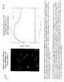
- a fluorescence image of the encoded cells is shown in Fig. 6.
- the fluorescent intensity response of the cells indicates a gradual increase as the lipophilic groups are cleaved from the BCECF-AM dye within the cell.
- the fluorescent intensity response of the wells which do not contain cells was negligible.
- BCECF-Dextran available from Molecular Probes, was used for cell viability measurements.
- a 0.1 uM solution of the dye was added to cell media contained within array microwells.
- BCECF requires excitation at two wavelengths, 490 nm and 440 nm, and the ratio of the emitted light intensity at 530 nm for each wavelength is proportional to pH.
- This dye is conjugated with a large Dextran group to prevent entry into the cell through the cell membrane.
- BCECF-Dextran can monitor decreases in pH within the external cell environment due to cell metabolism.
- Fig. 10 shows the average response of nine cells over time where the pH of the cell environment gradually decreases due to cell metabolism.
- a commercial cell viability assay LIVE / DEAD® from Molecular Probes (Eugene, OR), was employed.
- This assay provides a two-color fluorescence cell viability assay based on intracellular esterase activity and plasma membrane integrity.
- Live cells are distinguished by the enzymatic conversion of the cell-permeant non-fluorescent calcein AM to fluorescent calcein, with an excitation wavelength at 495nm and an emission wavelength at 515nm.
- Dead cells are distinguished by binding ethidium homodimer (EthD-1), with an excitation wavelength at 495nm and an emission wavelength at 635nm, to nucleic acids which is accompanied by a 40-fold increase in fluorescent intensity.
- EthD-1 is excluded by the intact plasma membranes of living cells. Background fluorescence levels are inherently low with this assay technique because the dyes are virtually non-fluorescent before interacting with cells.
- a working solution of 2 uM calcein AM and 4uM EthD-1 was prepared in serium-free medium.
- An array of NIH 3T3 mouse fibroblast cells was cultured at the distal face of a microwell array. The proximal face of the imaging fiber was focused on the imaging system. The cell array at the distal face of the imaging fiber was placed in serium-free medium without dye. The cell array was excited at 495nm and emission values from a population of 25 cells were acquired for 300ms at 515nm (Live) and 635nm (Dead). These values serve as background reading for these measurements.
- the cell array was then placed in the dye solution and the cell array was excited at 495nm and emission values from 25 cells were acquired for 300ms at 515nm (Live) and 635nm (Dead) every minute for 30 minutes. All measurements were performed at room temperature. Average fluorescent intensity for the live and dead cell wavelengths are plotted versus time after subtracting the background fluorescence measurement at each emission wavelength.
- This assay was used to evaluate pretreatment methods for filling the microwells of a biosensor arrray with culture media prior to inserting cells. By comparing the viability of cells placed in microwells after various treatments, it was determined that, in a preferred embodiment, sonicating the mircrowell array under vacuum for 15 minutes prior to insertion of cells improves viability by ensuring that the microwells are filled with culture media.
- Fig. 11a the average fluorescent intensity for dead cells and live cells is plotted with time where no pretreatment was utilized.
- results are plotted for a pretreated microwell array. Comparison of the two figures demonstrates the advantage of prefilling the microwells with culture media prior to cell insertion. In this example, when the microwell array was not sonicated prior to adding the cells the cells displayed immediate cell death. In this example, when the microwells were sonicated under vacuum to fill the arrays with culture media, the cells remained viable for approximately 20 minutes.
- a unique feature of the biosensor array of the present invention is that cells within each cell population are individually encoded for maintaining cell identity within the array when randomly mixed populations of cells are employed.
- Cells may be encoded with a single fluorophore or chromophore dye or ratios of such dyes.
- cells may be encoded by either injecting a non-toxic fluorescing compound into the cell cytoplasm or by employing natural or genetically-engineered cells lines which exhibit chemiluminescence or bioluminescence , such as green fluorescent protein mutants.
- a plurality of cell populations may be randomly mixed in the biosensor array, the identity and location of each cell type is determined via a characteristic optical response signature when the array is illuminated by excitation light energy.
- Cells may be encoded prior to disposing them in the microwells or, alternatively, following placement in the microwells.
- a single fluorophoric or chromophoric material or dye is used for encoding the cells.
- two or more encoding materials or dyes may be used to encode cell populations and the ratio of the optical response light intensity from each material or dye, produced by exposure to excitation light energy, is used to identify the positions of individual cells within the cell population and locate them in the array.
- cells may be encoded with dye compounds which are attached to cells, taken up by cells or provided in the local cell environment.
- a wide variety of fluorophores, chromophores, stains or a dye compounds may be used for encoding cells.
- Encoding dyes may be permeant or impermeant to the cell membrane.
- Impermeant dyes may be conjugated with acetoxymethyl ester to allow take up by cells.
- conventional conjugate or reactive cell membrane stains, cell tracers, or cell probes such as fluoresceins, rhodamines, eosins naphthalimides, phycobiliproteins, nitrobenzoxadiazole may be utilized.
- cyanine dyes such as SYTO® (Molecular Probes), amine-reactive dyes, thiol-reactive dyes, lipopilic dyes, and DNA intercalators, such as acridine orange, may be employed.
- fluorogenic or chromogenic enzyme substrates may be taken up by the cells, processesed by intracellular enzymes, such as glycosidases, phosphatases, luciferase, or chloramphenicol acetyltransferase, and provide encoding for cell populations.
- cell organelle dye probes may be employed for encoding.
- cell membrane probes such as carbocyanines and lipophilicaminostyrls may be utilized for encoding.
- Tables 1 and 2 provide a partial listing of a various types of dyes and their corresponding excitation and emission wavelengths which have utility for encoding cell populations in sensor arrays of the present invention.
- a particularly useful reference for selecting other types of encoding dyes is R.P. Haugland, Handbook of Fluorescent Probes and Research Chemicals (6 th ed.), Molecular Probes Inc.(Eugene, OR, 1996).
- Cell encoding eliminates the need for mechanically scanning the array, mechanically indexing the location of cells, and mechanically positioning the array for measurements of individual cells.
- simultaneous measurements of the entire array are possible since the responses of individual cells are readily associated with a specific cell population type because each cell is encoded. Encoding of cells thus provides for rapid, simultaneous measurements of all cells and cell populations within the array without the need to mechanically scan the array to acquire a series of sequential measurements for each cell. Since monitoring and measuring the responses of all cells in the array occurs simultaneously, without a prolonged delay between the first cell measurement and last cell measurement, the biosensor array of the present invention provides the capability to monitor both short term and long term cell responses to biological stimuli.
- the biosensor array of the present invention thus has the unique ability for measuring both cell responses and response rates to analytes.
- This feature provides 1.
- Amine-Reactive Probes fluorescein isothiocyanate 494ex/519em carboxyfluorescein succinimidyl esters 504ex/529em carboxyeosin succinimidyl esters 492ex/517em additional discriminating response information which is useful for detecting biological or chemical analytes of interest.
- PKH67 with an excitation wavelength of 490 nm and an emission wavelength of 502 nm
- PKH26 with an excitation wavelength of 551 nm and an emission wavelength of 567 nm
- PKH26 and PKH67 are part of a family of dyes manufactured by Zynaxis Cell Science (Malvern, PA), sold under the trademark Zyn-Linker® (Phanos Technologies Inc.), produced by the method of U.S. Patent 5,665,328 to Hogan, et al., and available from Sigma (St.Louis, Mo).
- both dyes were applied to suspended fibroblast cells to encode the cells prior to placement in the sensor array.
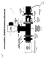
- Encoded cells were placed in microwells filled with growth media. The encoded cells were then illuminated with excitation light transmitted through the fiber optic array and the resulting fluorescent emission response of cells was collected through the same fiber and passed to the detection system.
- Fig. 6 shows a typical fluorescence optical image of a PKH26 encoded cell population in a biosensor array of the present invention.
- Fig. 8 shows a typical fluorescence image of a PKH67 encoded cell population in a biosensor array. Note that only those microwells containing encoded cells yields a fluorescent signal upon excitation at the encoding dye wavelength.
- external or internal encoding labels are applied to suspended cell populations prior to placement in the sensor array.
- an external label is applied to the cell by first washing the suspended cells with serum-free media and then centrifuging the cells into a loose pellet at 2000 RPM for 5 minutes. The supernatant is drawn off and the centrifuge tube is tapped to resuspend the cells. Approximately 1 mL of Diluent C, available as dye kit from Sigma, was added to the cells and the tube was inverted to mix. Immediately prior to encoding, a solution of 4 x 10 -6 M Diluent C dye was prepared. The suspended cells are added to the dye solution, mixed by pipetting the cell/dye solution, and incubated for 5 minutes.
- encoded NIH 3T3 mouse fibroblast cells were dispersed in microwells in sensor array and the location of encoded cells within the array was determined by excitation of the cells at a wavelength of 551 nm.
- the encoded cells form a characteristic, detectable fluorescence pattern within the sensor array where the pattern provides a locational template for cell viability measurements using BCECF and an excitation wavelength of 505 nm.
- the excitation and emission wavelengths of the PKH26 encoding label and the BCECF-AM dye are sufficiently separated so that there is no interference between the two dyes.
- FIG. 6 is a characteristic fluorescence image pattern identifying the location of PKH26 encoded cells in the biosensor array. A similar procedure was followed for encoding the mouse fibroblast cells with PKH67 where a corresponding characteristic fluorescence image pattern is shown in Fig. 8.
- each cell population within the array may be encoded with unique dye ratios which yield a characteristic fluorescent intensity ratio in a distinct wavelength range.
- a range of dye ratios may be employed with two or more dye combination for producing a series of encoding ratios useful for a identifying a large number of cell populations.
- the fluorescent intensity ratio produced by a specific dye ratio which is used for encoding a cell population, can be distinguished by taking the mean intensity minus the background intensity at each emission wavelength and then dividing the two values to obtain the range for that particular ratio.
- two separate populations of NIH 3T3 mouse fibroblast cells were encoded by labeling cell membranes with either a 1:5 or a 5:1 ratio of PHK67 and PHK26 dyes. Each cell population comprised approximately 125 encoded cells. The cell populations were illuminated at 490 nm and 551 nm excitation wavelengths and emitted fluorescent intensity ratios were measured at 502 nm and 567 nm. Measurements of the average intensity ratio for each dye ratio were made over a two day period. The initial average intensity ratio for the 1:5 PKH67/PKH26 ratio was 0.0863 and the ratio for the 5.1 dye ratio was 0.7014.
- dye ratios can provide a useful alternative encoding mechanism for identifying and locating cell populations which are randomly dispersed on a biosensor array of the present invention.
- optical responses of individual cells and cell populations to chemical or biological stimuli are typically interrogated and detected by coupling individual cells with appropriate indicators which may be either fluorophores, chromophores, stains or a dye compounds. Any suitable indicator or combinations of indicators may be utilized provided the indicator does not compromise cell response.
- indicators may be incorporated directly into the cell by attachment to the cell membrane, by absorption into the cell cytoplasm by membrane permeant indicators, or by microinjection into the cell cytoplasm.
- ultrafine fluorescing microspheres such as Molecular Probes FluoSpheresTM, are ingested by the cells and are employed as indicators.
- indicators are added to the culture media fluid contained within the microwells.
- indicators may be attached to the surface of the microwells by a conventional Reactive pH indicator dyes pH Indicator Preferred Reactive Form BCECF BCECF (B-1151, see Section 23.2) Carboxyfluorescein 5-(and-6)-carboxyfluorescein, succinimidyl ester (C-1311, see Section 1.3) Cl-NERF Cl-NERF (C-683), see Section 233.) Dichlorofluorescein 2',7'-dichlorofluorescein-5-isothiocyanate (D-6078, see Section 1.5) Dimethylfluorescein 5-(and-6)-carboxy-4',5'-dimethylfluorescein(C-366, see Section 23.2) DM-NERF DM-NERF (D-6830, see Section 23.3) Naphthofluorescein 5-(and-6)-carboxynaphthofluorescein, succinimidyl ester (C-653) Oregon GreenTM 488 Oregon GreenTM
- natural or genetically engineered cell lines which exhibit chemiluminescence, bioluminesence, or color changes when stimulated are used alone without need for a separate indicator since they produce intrinsic optical responses.
- examples of such cells include green fluorescent protein mutants.
- cells which express enzymes are employed with a reagent which enables an optical response, such as the generation of a fluorescent product. For example when luciferase is expressed by a cell in the presence of luciferen, the cell produces a fluorescence response when biologically stimulated.
- multiple indicators may be employed within a cell array, within a cell population, or within individual cells so as to provide for simultaneous monitoring of cell responses to a variety of different chemical or biological materials. Where two or more indicators are utilized, dyes with spectral separation of narrow spectral bandwidths are particularly useful, for example Molecular Probes BODIPYTM dyes.
- Individual cells and populations of cells within the biosensor array of the present invention may be optically interrogated and cell responses may be monitored by employing conventional optical components known to one of ordinary skill in the art.
- conventional light sources such as arc lamps, photodiodes, or lasers may be employed for excitation light energy.
- Cell responses may be monitored by conventional detectors such as photomultiplier tubes, photodiodes, photoresistors or charge coupled device (CCD) cameras.
- Conventional optical train components such as lenses, filters, beam splitters, dichroics, prisms and mirrors may be employed to convey light to an from such light sources and detectors either to discrete substrate sites or through optical fiber strands to microwells that contain individual cells.
- any particular optical apparatus configuration that is employed in optical measurements is that the combination of optical components provide for optically coupling the cells in the array to detectors and light sources. While a particular apparatus configuration that was employed in experimental optical measurements is described below, other configurations may also be employed which are functionally equivalent and appropriate suited for a particular measurement requirement.
- the instrumentation used for fluorescence measurements is a modified Olympus (Lake Success, NY) epifluorescence microscope which was converted from a vertical to a horizontal configuration.
- a schematic diagram of the measurement system 100 is shown in Fig. 9.
- White light from a 75W xenon lamp 110 is collimated by a condensing lens 112, passed through an excitation filter 120, reflected by a dichroic mirror 130, and focused onto the proximal end 210 of an imaging fiber 200 with a microscope objective 140.
- a neutral density filter 122 may be employed for adjustment of excitation light intensity.
- the imaging fiber 200 is precisely positioned by an x-y micropositioner 150, available from Spindler and Hoyer (Milford, MA), and a microscope z-translation stage 152.
- Excitation light is transmitted through the fiber 200 to the biosensor array 300 at the distal fiber end 212.
- the emitted fluorescence light from the biosensor array is returned through the fiber 200, through the dichroic mirror 130, filtered through an emission filter 160, and detected by a PXLTM Photometrics (Tuscon, AZ) charge coupled device (CCD) camera 170.
- a magnification lens 165 may be employed if necessary.
- Data is processed on an Apple Power Macintosh 440 (Sunnyvale, CA) desktop computer 180 using IPLab 3.0 image processing software, commercially available from Signal Anatytics (Vienna, VA). While a bench-top measurement system was utilized for these measurements, in one embodiment, a compact portable measurement system may be assembled from conventional optical and electronic components.
- the biosensor, biosensor array, sensing apparatus and sensing method of the present invention can be applied to a large variety of conventional assays for screening and detection purposes.
- the biosensor may be configured for virtually any assay and offers a distinct advantage for high throughput screening where a plurality of encoded cell populations, which have utility in particular assays or are genetically engineered cell to provide unique responses to analytes, may be employed in a single sensor array for conducting a large number of assays simultaneously on a small sample.
- the biosensor array thus provides both for tremendous efficiencies in screening large combinatorial libraries and allows conduction of a large number of assays on extremely small sample volumes, such as biologically important molecules synthesized on micron sized beads.
- the biosensor of the present invention can be applied to virtually any analyte measurements where there is a detectable cell response to the analyte due to biological stimulation.
- the biosensor array and method of the present invention utilizes the unique ability of living cell populations to respond to biologically significant compounds in a characteristic and detectable manner. Since the selectivity of living cells for such compounds has considerable value and utility in drug screening and analysis of complex biological fluids, a biosensor which makes use of the unique characteristics of living cell populations offers distinct advantages in high throughput screening of combinatorial libraries where hundreds of thousands of candidate pharmaceutical compounds must be evaluated. In addition, such a biosensor and sensing method can be utilized for either off-line monitoring of bioprocesses or in situ monitoring of environmental pollutants where the enhanced sensitivity of living cells to their local environment can be exploited.
- the present invention provides methods for detecting the responses of individual cells to analytes of interest.
- analyte of interest or “target analyte” or “candidate bioactive agent” or “candidate drug” or grammatical equivalents herein is meant any molecule, e.g., protein, oligopeptide, small organic molecule, polysaccharide, polynucleotide, etc., to be tested for the ability to directly or indirectly altering a cellular phenotype, including its optical properties.
- assay mixtures are run in parallel with different agent concentrations to obtain a differential response to the various concentrations.
- one of these concentrations serves as a negative control, i.e., at zero concentration or below the level of detection.
- Analytes encompass numerous chemical classes, though typically they are organic molecules, preferably small organic compounds having a molecular weight of more than 100 and less than about 2,500 daltons.
- Analytes comprise functional groups necessary for structural interaction with proteins, particularly hydrogen bonding, and typically include at least an amine, carbonyl, hydroxyl or carboxyl group, preferably at least two of the functional chemical groups.
- the candidate agents often comprise cyclical carbon or heterocyclic structures and/or aromatic or polyaromatic structures substituted with one or more of the above functional groups.
- Candidate agents are also found among biomolecules including peptides, saccharides, fatty acids, steroids, purines, pyrimidines, derivatives, structural analogs or combinations thereof. Particularly preferred are peptides.
- Candidate agents are obtained from a wide variety of sources including libraries of synthetic or natural compounds. For example, numerous means are available for random and directed synthesis of a wide variety of organic compounds and biomolecules, including expression of randomized oligonucleotides. Alternatively, libraries of natural compounds in the form of bacterial, fungal, plant and animal extracts are available or readily produced. Additionally, natural or synthetically produced libraries and compounds are readily modified through conventional chemical, physical and biochemical means. Known pharmacological agents may be subjected to directed or random chemical modifications, such as acylation, alkylation, esterification, amidification to produce structural analogs.
- the candidate bioactive agents are naturally occuring proteins or fragments of naturally occuring proteins.
- cellular extracts containing proteins, or random or directed digests of proteinaceous cellular extracts may be used.
- libraries of procaryotic and eucaryotic proteins may be made for screening in the methods of the invention.
- Particularly preferred in this embodiment are libraries of bacterial, fungal, viral, and mammalian proteins, with the latter being preferred, and human proteins being especially preferred.
- the peptides may be digests of naturally occuring proteins as is outlined above, random peptides, or “biased” random peptides.
- randomized or grammatical equivalents herein is meant that each nucleic acid and peptide consists of essentially random nucleotides and amino acids, respectively. Since generally these random peptides (or nucleic acids, discussed below) are chemically synthesized, they may incorporate any nucleotide or amino acid at any position.
- the synthetic process can be designed to generate randomized proteins or nucleic acids, to allow the formation of all or most of the possible combinations over the length of the sequence, thus forming a library of randomized candidate bioactive proteinaceous agents.
- the library is fully randomized, with no sequence preferences or constants at any position.
- the library is biased. That is, some positions within the sequence are either held constant, or are selected from a limited number of possibilities.
- the nucleotides or amino acid residues are randomized within a defined class, for example, of hydrophobic amino acids, hydrophilic residues, sterically biased (either small or large) residues, towards the creation of nucleic acid binding domains, the creation of cysteines, for cross-linking, prolines for SH-3 domains, serines, threonines, tyrosines or histidines for phosphorylation sites, etc., or to purines, etc.
- nucleic acid candidate bioactive agents may be naturally occuring nucleic acids, random nucleic acids, or “biased” random nucleic acids.
- digests of procaryotic or eucaryotic genomes may be used as is outlined above for proteins.
- Nucleic acids in this context includes both DNA and RNA, and nucleic acid analogs including PNA.
- the candidate bioactive agents are organic chemical moieties, a wide variety of which are available in the literature.
- the biosensor array can be employed for remotely monitoring redox states of individual cells or cell populations in bioprocesses.
- NADH dependent fluorescence can be measured in bacteria, fungi, plant or animal cells.
- NAD(P) /NAD(P)H can be measured to monitor changes from aerobic to anaerobic metabolism in fermentation processes using the method disclosed by Luong, et al., in Practical Fluorescence , G. Guilbault ed., Marcel Dekker (New York, 1990).
- the biosensor array may be employed for in situ monitoring of cellular processes in response to environmental contaminants by incorporating the method disclosed by Hughes, et al., Analytica Chimica Acta 307:393(1995) to provide for distinguishable cell population responses within an array.
- this method micron-sized spheres, impregnated with a fluorophore and modified on the surface with a fluorogenic enzyme probe, are ingested by cells and enzymatic activity occurs at the sphere surface, producing a detectable fluorescent signal.
- the biosensor array can be employed with genetically engineered bioluminescent bacteria for in situ monitoring and optical sensing of metallic compounds.
- cell population responses to antimonite and arsenite may be utilized by incorporating the method disclosed in Ramanathan, et al., Anal Chem. 69:3380(1997) into cell populations within the biosensor array. With this method, cell plasmid regulates the expression of bacterial luciferase depending on the metal concentration.
- the cell populations within the biosensor array can be encoded with ATP dependent luminescent proteins, for example firefly luciferase, which are injected into rat hepatocytes for pathological studies according to the method disclosed by Koop, et al., Biochem. J. 295:165(1993). These cells exhibit a decrease in cytoplasmic ATP when exposed to pathological insults and changes in fluorescence directly relate to the extent of metabolic poisoning in the cell.
- ATP dependent luminescent proteins for example firefly luciferase
- the cell populations within the biosensor array can be encoded with green fluorescent protein [see T. Gura, Science 276:1989(1997); Niswender, et al., J. Microscopy 180(2):109(1995); Cubitt, et al., TIBS 20:448(1995); Miyawaki, et al., Nature 388:882(1997)].
- green fluorescent protein see T. Gura, Science 276:1989(1997); Niswender, et al., J. Microscopy 180(2):109(1995); Cubitt, et al., TIBS 20:448(1995); Miyawaki, et al., Nature 388:882(1997).
- GFP green fluorescent protein
- the biosensor array can be used in measurements of cell proliferation by in situ monitoring of calcium levels and calcium oscillations in single cells using fluorescent markers, such as aequorin or fura-2, according to the method disclosed by Cobbold, et al., Cell Biology 1:311(1990).
- the assays of the invention may be run in a wide variety of ways and for a wide variety of purposes.
- the cells may be used as a detection system for a particular analyte; the cells undergo a characteristic optically detectable change in the presence of a particular analyte.
- the cells may be used to screen drug candidate libraries for the ability to alter a cellular phenotype that is optically detectable.
- the expression of a therapeutically relevant cell surface receptor may be increased such that the receptor can now bind a fluorescent ligand; similarly a therapeutically relevant enzyme may now be activated such that a fluorescent reaction product is generated. In this way any modulation, incluing both increases and descreases, may be monitored.
- the use of reporter genes such as green fluorescent proteins and derivatives thereof facilitates high throughput screening for relevant analyte interactions, through the use of inducible promoters, for example.
- a candidate bioactive agent is added to the cells prior to analysis, and the cells allowed to incubate for some period of time.
- administration or “contacting” herein is meant that the candidate agent is added to the cells in such a manner as to allow the agent to act upon the cell, whether by uptake and intracellular action, or by action at the cell surface.
- nucleic acid encoding a proteinaceous candidate agent i.e. a peptide
- a viral construct such as a retroviral construct and added to the cell, such that expression of the peptide agent is accomplished; see WO 97/27212.
- the cells can be washed if desired and are allowed to incubate under preferably physiological conditions for some period of time.
- the reactions outlined herein may be accomplished in a variety of ways, as will be appreciated by those in the art. Components of the reaction may be added simultaneously, or sequentially, in any order.
- the reaction may include a variety of other reagents may be included in the assays. These include reagents like salts, buffers, neutral proteins, e.g. albumin, detergents, etc which may be used to facilitate optimal detection, and/or reduce non-specific or background interactions. Also reagents that otherwise improve the efficiency of the assay, such as protease inhibitors, nuclease inhibitors, anti-microbial agents, etc., may be used.
- labeled herein is meant that the compound is either directly or indirectly labeled with a label which provides a detectable signal, e.g. radioisotope, fluorescers, enzyme, antibodies, particles such as magnetic particles, chemiluminescers, or specific binding molecules, etc.
- Specific binding molecules include pairs, such as biotin and streptavidin, digoxin and antidigoxin etc.
- the complementary member would normally be labeled with a molecule which provides for detection, in accordance with known procedures, as outlined above.
- the label can directly or indirectly provide a detectable signal.
- the data is analyzed to determine the experimental outcome, i.e. either the presence or absence of a target analyte, the effect of a candidate agent on a cellular phenotype, etc. This is generally done using a computer.
- bioactive agents are identified.
- Compounds with pharmacological activity are able to alter a cellular phenotype.
- the compounds having the desired pharmacological activity may be administered in a physiologically acceptable carrier to a host, as previously described.
- the agents may be administered in a variety of ways, orally, parenterally e.g., subcutaneously, intraperitoneally, intravascularly, etc.
- the compounds may be formulated in a variety of ways.
- the concentration of therapeutically active compound in the formulation may vary from about 0.1-100 wt.%.
- compositions can be prepared in various forms, such as granules, tablets, pills, suppositories, capsules, suspensions, salves, lotions and the like.
- Pharmaceutical grade organic or inorganic carriers and/or diluents suitable for oral and topical use can be used to make up compositions containing the therapeutically-active compounds.
- Diluents known to the art include aqueous media, vegetable and animal oils and fats. Stabilizing agents, wetting and emulsifying agents, salts for varying the osmotic pressure or buffers for securing an adequate pH value, and skin penetration enhancers can be used as auxiliary agents.
Landscapes
- Health & Medical Sciences (AREA)
- Chemical & Material Sciences (AREA)
- Immunology (AREA)
- Life Sciences & Earth Sciences (AREA)
- Physics & Mathematics (AREA)
- Engineering & Computer Science (AREA)
- General Health & Medical Sciences (AREA)
- Hematology (AREA)
- Analytical Chemistry (AREA)
- Urology & Nephrology (AREA)
- General Physics & Mathematics (AREA)
- Biomedical Technology (AREA)
- Pathology (AREA)
- Biochemistry (AREA)
- Molecular Biology (AREA)
- Clinical Laboratory Science (AREA)
- Medicinal Chemistry (AREA)
- Cell Biology (AREA)
- Biotechnology (AREA)
- Food Science & Technology (AREA)
- Spectroscopy & Molecular Physics (AREA)
- Microbiology (AREA)
- Chemical Kinetics & Catalysis (AREA)
- Apparatus Associated With Microorganisms And Enzymes (AREA)
- Investigating Or Analysing Materials By The Use Of Chemical Reactions (AREA)
- Measuring Or Testing Involving Enzymes Or Micro-Organisms (AREA)
- Investigating, Analyzing Materials By Fluorescence Or Luminescence (AREA)
- Investigating Or Analysing Biological Materials (AREA)
Abstract
Description
- The present invention is generally concerned with biosensors, biosensor arrays, and sensing apparatus, and sensing methods for the analysis of chemical and biological materials. More particularly, the invention is directed to biosensors, biosensor arrays, sensing apparatus and sensing methods which employ cells and mixed populations of cells for analysis of chemical and biological materials.
- It is generally recognized that important technical advances in chemistry, biology and medicine benefit from the ability to perform microanalysis of samples in minute quantities. However, making analytical measurements on minute quantities has long been a challenge due to difficulties encountered with small volume sample handling, isolation of analytes, and micro-analysis of single-cell physiology.
- Nanoliter, picoliter, and femtoliter volume studies have been explored in a range of applications involving in vitro and in vivo cellular investigations [R.M. Wightman, et al., Proc. Natl. Acad. Sci. U.S.A. 88:10754(1991); R.H.Chow, et al. Nature 356:60(1992); T.K. Chen, et al. Anal. Chem. 66:3031 (1994); S.E. Zerby, et al., Neurochem. 66:651(1996); P.A. Garis, et al. J.Neurosci. 14:6084(1994); G.Chen, et al., J.Neurosci. 15:7747(1995)], electrochemistry [R.A. Clark, et al., Anal. Chem. 69(2):259(1997)], matrix-assisted laser desorption- ionization mass spectrometry [S. Jespersen, et al., Rapid Commun. Mass Spectrom. 8:581(1994)], micro-column liquid chromatography [I.A.Holland, et al., Anal.Chem. 67:3275(1995); M.D. Oates, et al., Anal. Chem. 62:1573(1990)], micro-titration [M. Gratzl, et al Anal. Chem. 65:2085(1993); C.Yi, et al., Anal. Chem. 66:1976(1994)], and capillary electrophoresis [M.Jansson, et al., J.Chromatogr. 626:310(1992); P.Beyer Hietpas, et al. J.Liq. Chromatogr. 18:3557(1995)].
- Clark, et al. [Anal. Chem. 69(2):259(1997)] has disclosed a method for fabricating picoliter microvials for electrochemical microanalysis using conventional photolithographic masking and photoresist techniques to transfer mold polystyrene microvials on silicon wafer templates. These microvials typically exhibit non-uniformity in size and shape due to the difficulty in controlling the resist etching of the molding surface and the transfer molding process.
- Park, et al. [Science 276:1401(1997)] has disclosed a modified lithographic method for producing arrays of nanometer-sized holes using polystyrene-polybutadiene, ordered, diblock copolymers as masks in reactive ion etching of silicon nitride. This multi-step method is capable of producing arrays of picoliter-sized holes which are typically 20 nanometers in diameter and 20 nanometers deep with a spacing of 40 nanometers. Hole densities of up to 1011 holes/cm2 are disclosed. The range of sizes and spacings of the holes produced by this method is limited by the size of the copolymer microdomains. Uniformity of hole size and spacing is difficult to maintain with this method due to difficulties in controlling the etching method employed to form the holes.
- Deutsch, et al. [Cytometry 16:214(1994)] have disclosed a porous electroplated nickel microarray comprised of micron-sized conical holes in blackened nickel plate. Hole sizes range from a 7 um upper diameter to a 3 um lower diameter with an 8 um depth. The array is used as a cell carrier for trapping individual cells while studying the responses of individual cells to changes in their microenvironment. In U.S. Patent 4,772540, Deutsch, et al., have also disclosed a method for making such an array using a combined photoresist and electroplating technique.
- Coming Incorporated (Coming, NY) (FR-A-2 741 357), disclose a process for the manufacture and application of a support plate for a dense two dimensional network of microwells of very small dimensions, from a thermoformable material such as plastic or glass. The microwells are approximately 100um apart with a depth of 20um and a bottom diameter of 40um, at a density of 104 wells/cm2.
- Corning Costar Corp. (Acton, Ma) produces a commercial microwell array for miniaturized assays under the trademark PixWell™. These arrays are made from microformed glass plates and comprise 40 um diameter by 20 um deep tapered wells with a well density of 4356 wells/cm2.
- Microwell arrays have particular utility in the study of living cells. In cell research, the measurement of responses of individual cells to changes or manipulations in their local environment is desirable. Any method or device designed for such studies must provide for the capability of maintaining cell viability, identifying the location of individual cells, and correlating response measurements with individual cells.
- Due to the availability of viable fluorescent probes for intracellular studies, fluorescence measurements of living cells have significant utility in the study of cell functions. Thus fluorescence optical measurements are often utilized in cell studies where three generic methods of cell measurement are available, comprising bulk measurements of cell populations, dynamic measurements of cell populations or individual cells, and static measurements of individual cells.
- The characteristics of an entire cell population as a whole can be studied with bulk measurements of sample volumes having a plurality of cells. This method is preferred where cell populations are very homogeneous. A generally recognized limitation of this method is the presence of background fluorescence which reduces the sensitivity of measurements and the inability of distinguishing differences or heterogeneity within a cell population.
- Flow cytometry methods are often employed to reduce problems with background fluorescence which are encountered in bulk cell population measurements [M.R.Gauci, et al., Cytometry 25:388(1996); R.C.Boltz, et al., Cytometry 17:128(1994)]. In these methods, cell fluorescence emission is measured as cells are transported through an excitation light beam by a laminar flowing fluid. Flow cytometry methods may be combined with static methods for preliminary sorting and depositing of a small number of cells on a substrate for subsequent static cell measurements [U.S. Patent No. 4,009,435 to Hogg, et al.; Kanz, et al., Cytometry 7:491(1986); Schildkraut, et al., J.Histochem Cytochem 27;289(1979)].
- Gauci, et al., disclose a method where cell size, shape and volume is measured by light scattering and fluorescent dyes are utilized to determine protein content and total nucleic acid content of cells. This method further provides for counting and sizing various cells at a rate of approximately 100 cells per second.
- Flow cytometry techniques are generally limited to short duration, single measurements of individual cells. Repetitive measurements on the same cell over time are not possible with this method since typical dwell times of a cell in the excitation light beam are typically a few microseconds. In addition, the low cumulative intensity from individual cell fluorescence emissions during such short measurement times reduces the precision and limits the reliability of such measurements.
- Regnier, et al., [Trends in Anal.Chem. 14(4):177(1995)] discloses an invasive, electrophoretically mediated, microanalysis method for single cell analysis. The method utilizes a tapered microinjector at the injection end of a capillary electrophoresis column to pierce an individual cell membrane and withdraw a sample of cytoplasm. The method measures cell contents, one cell at a time. The method is generally limited to the detection of easily oxidized species.
- Hogan, et al., [Trends in Anal.Chem. 12(1):4(1993)] discloses a microcolumn separation technique which may be utilized in combination with either a conventional gas chromatograph-mass spectrometer, micro thin layer chromatography or high pressure liquid manipulation of small cellular volumes. The sensitivity of the method is limited and may require pre-selection of target compounds for detection.
- Static methods are generally the preferred method for measurements on individual cells. Measurement methods range from observing individual cells with a conventional optical microscope to employing laser scanning microscopes with computerized image analysis systems [see L. Hart, et al., Anal. Quant. Cytol. Histol. 12:127(1990)]. Such methods typically require the attachment of individual cells to a substrate prior to actual measurements. Problems are typically encountered in attaching single cells or single layers of cells to substrates and in maintaining cells in a fixed location during analysis or manipulation of the cell microenvironment. Additionally, repetitive measurements on individual cells typically require physically indexing the location of individual cells and providing a mechanism for scanning each cell sequentially and returning to indexed cell locations for repeated analysis of individual cells.
- Huang, et al., [Trends in Anal. Chem., 14(4)158(1995)] discloses a static electrochemical method and electrode for monitoring the biochemical environment of single cells. The method requires fabrication and manual positioning of a microelectrode reference and working electrode within the cell. The method has been used to detect insulin, nitric oxide and glucose inside single cells or external to the cells. The method is generally limited to the study of redox reactions within cells.
- Ince, et al. [J.Immunol. Methods 128:227(1990)] disclose a closed chamber device for the study of single cells under controlled environments. This method employs a micro-perfusion chamber which is capable of creating extreme environmental conditions for cell studies. Individual cells are held in place by two glass coverslips as various solutions are passed through the chamber. One limitation of the method is the difficulty in eliminating entrapped gas bubbles which cause a high degree of autofluorescence and thus reduces the sensitivity of measurements due to background fluorescence.
- In an attempt to overcome the limitations encountered with conventional static methods, Deutsch, et al., [Cytometry 16:214(1994)] and Weinreb and Deutsch, in U.S. Patent Nos. 4,729,949, 5,272,081, 5,310,674, and 5,506,141, have disclosed an apparatus and method for repetitive optical measurements of individual cells within a cell population where the location of each cell is preserved during manipulation of the cell microenvironment.
- A central feature of the apparatus disclosed by Deutsch, et al., is a cell carrier, comprising a two dimensional array of apertures or traps which are conical-shaped in order to trap and hold individual cells by applying suction. The cell carrier is typically fabricated by the combined electroplating-photoresist method disclosed in U.S. Patent 4,772540 to Deutsch, et al. The purpose of the cell carrier is to provide a means for maintaining the cells in fixed array locations while manipulating the cell environment. Individual cells are urged into cell carrier holes by suction and the wells are subsequently illuminated with a low-intensity beam of polarized light that reads back-emitted polarization and intensity. Measurements are compared when two different reagents are sequentially reacted with the cells. The method as disclosed requires two separate cell carriers for both a baseline control and analyte measurement.
- The method and device of Deutsch, et al., have been employed by pathologists in diagnostic tests to determine the health and viability of cell samples taken from patients. The method and device have been applied to both cancer screening [Deutsch, et al., Cytometry 16:214(1994), Cytometry 23:159(1996), and European J. Cancer 32A(10):1758(1996)] and rheumatoid arthritis [Zurgil, et al., Isr.J.Med.Sci. 33:273(1997)] in which fluorescence polarization measurements are used to differentiate lymphocytes of malignant versus healthy cells based on changes in the internal viscosity and structuredness of the cytoplasmic matrix induced by exposure to tumor antigen and mitogens.
- The method and device disclosed by Deutsch, et al., requires employment of a scanning table driven by three stepping motors and a computer control system for mapping, indexing and locating individual cells in the cell carrier. The use of such mechanical scanning methods introduces limitations in reproducibility and accuracy of measurements due to conventional mechanical problems encountered with backlash and reproducible positioning of individual cell locations for repeated measurements. In addition, mechanical scanning of the entire array prolongs the measurement time for each cell in the array.
- The method disclosed by Deutsch, et al., is further limited by the use of fluorescence polarization measurements which have certain intrinsic limitations due to the significant influence of various optical system components on polarization as the fluorescence emission response is passed from the cell carrier to optical detectors. Birindelli, et al. [European J. Cancer 33(8):1333(1997)], has also identified limitations in this method due to fluctuations in electropolarisation values which require taking averages of at least three measurement scans for each condition so as to obtain reliable measurements. In addition, for cell studies, polarization measurements are generally limited to cell responses which produce sufficient changes in cytoplasm viscosity to produce a detectable change in polarization. Since not all cell responses are accompanied by detectable viscosity changes, the method is further limited to the cell activities which create such viscosity changes in the cytoplasm.
- Zare, et al., [Science 267:74(1995); Biophotonics International, March-April, p17 (19995)] discloses a biosensor system based on the response of living cells to complex biological materials fractionated by a microcolumn separation technique. Cells which were positioned on a glass cover slip were treated with a fluorescent probe and subsequently shown to be sensitive to a series of biological compounds including acetylcholine, bradykinin, and adenosine triphosphate as well as changes in intracellular calcium levels.
- Yeung, et al. [Acc. Chem. Res. 27:409(1994)] has reviewed a number of methods for single cell response studies and has observed a significant variation and heterogeneity within cell populations based on analyte measurements. For example, the reference discloses a capillary electrophoresis method for exposing cells to biologically reactive compounds, extracting the intracellular fluid of individual cells produced in response to such compounds, and identifying analytes from migration times in the capillary column. Other fluorescence-based assays are also disclosed. Significant cell-to-cell variations and heterogeneity in individual cell responses within a cell population were observed which differences could provide a means for discriminating between biological and chemical compounds in contact with individual cells.
- Shimadzu Corporation (Japan) (EP-A-0 539 888), disclose a device for selecting granular cells or microorganisms using a detector to measure optical density of the cells. The stored information is used by a control device to move a pickup member to pickup the required cells. The selected cells can then be released for further analysis or processing.
- McConnell, et al. [Science, 257:1906(1992)], disclose a microphysiometer device known as the "Cytosensor" which uses a light addressable potentiometer sensor to measure the rate at which cells acidify their environment. This sensor acts as miniaturized pH electrode for monitoring cell responses which produce detectable changes in local pH. The disclosed device is limited to the measurement of proton excretions from cells and thus is only capable of detecting acidic cell responses to analytes.
- U.S. Patent No. 5,177,012 to Kim, et al., disclose a biosensor for the determination of glucose and fructose. The biosensor is produced by treating whole cells with an organic solvent and immobilizing the treated cells residue on a support to form a whole cell membrane which is applied to a pH electrode.
- Trustees of Tufts College (USA) (WO 99/18434) disdose a microsphere-based analytical system. Self-encoding microspheres with distinct optical responses to specific target analytes, maybe mixed together whilst the ability is retained to identify the microsphere type and location. In addition, an optical fibre bundle sensor is disclosed in which individual microsphere sensors are located in microwells at the distal end of the fibre bundle and are optically coupled to discrete fibres or fibre groups within the bundle. This document falls under Art 54 (3) EPC.
- U.S. Patent No. 5,690,894 to Pinkel, et al., discloses a biosensor which employs biological "binding partners", materials such as nucleic acids, antibodies, proteins, lectins and other materials derived from cells, tissues, natural or genetically-engineered organisms. These agents are used in conjunction with a fiber optic array where each species of binding partners is uniquely addressed by a group of fibers within the fiber optic bundle which is coupled to an optical detector. The array was designed for screening of extensive arrays of biological binding partners.
- While many of the prior art methods provide for the analysis of either single cells or populations of cells and some of these methods provide for monitoring cell responses to target analytes, none of the disclosed methods provides for employing large populations of monocultures or mixed populations of living cells for simultaneously monitoring the responses of individual cells to biological stimuli produced by chemical and biological analytes. Thus there is a need for a biosensor array and method which efficiently utilizes the ability of populations of living cells to respond to biologically significant compounds in a unique and detectable manner. Since the selectivity of living cells for such compounds has considerable value and utility in drug screening and analysis of complex biological fluids, a biosensor which makes use of the unique characteristics of living cell populations would offer distinct advantages in high throughput screening of combinatorial libraries where hundreds of thousands of candidate pharmaceutical compounds must be evaluated. In addition, such a sensor would be useful in monitoring bioprocesses and environmental pollution where the enhanced sensitivity of living cells to their environment can be exploited.
- In general, the invention provides for a biosensor and a biosensor array as set out in the claims for the analysis of chemical and biological materials. More particularly, the invention provides for biosensors and biosensor arrays, sensing apparatus and sensing methods which employ living cells and mixed populations of living cells for analysis of chemical and biological materials.
- The biosensor array of the present invention comprises either a monoculture of living cells or randomly mixed populations of living cells wherein each individual cell in the array is positioned on a substrate at an optically-addressable, discrete site which accomodates the size and-shape of individual cells. In one embodiment, the discrete site comprises a microwell or microcavity which is preformed to accommodate the size and shape of the individual cells. The biosensor array sensing method relies on the well known fact that individual cells, which are chemically or biologically stimulated by the presence of a biological or chemical material in the cell environment, will respond by producing a change in the cell or cellular environment which can be optically interrogated and detected within the cell itself or from an indicator compound, for example, a fluorophore, chromophore or dye, either attached to the cell, taken up in the cell, or added to the local cell environment. The biosensor of the present invention thus capitalizes on the ability of living cells to respond to biologically significant compounds. Since the selectivity of living cells for such compounds has considerable value and utility in drug screening and analysis of complex biological fluids, the biosensor of the present invention offers distinct advantages to high throughput screening of combinatorial libraries where hundreds of thousands of candidate compounds must be evaluated.
- As will be appreciated by one skilled in the art, a variety of substrate materials and substrate configurations may be employed with the biosensor array of the present invention. Any substrate or material that can be adapted to provide discrete sites that are appropriate for the attachment or association of individual cells and is accessible for optical interrogation of the cell array and detection of cell responses would be particularly useful as an array substrate. Candidate substrate materials include, but are not limited to, glasses, polymers, ceramics, metals, and composites formed from these materials. Substrate surface geometries may be planer, spherical, concave, convex, and textured. Preferably, a suitable substrate would be configured so as to provide for optical interrogation of the array and detection of cell responses to analytes of interest.
- The biosensor array of the present invention is incorporated into a fiber optic array which serves as a substrate for cell placement. By "fiber optic array" or other grammatical equivalents herein is meant a plurality of individual fibers or fiber strands that may be either grouped together as discrete, individual fibers in a fiber bundle or, alternatively, joined along their axial dimensions as a preformed unitary fiber optic array. The individual fibers in such an array may be arranged in a uniform or coherent configuration, for example as in an imaging fiber, or may be randomly oriented and incoherent. When a fiber optic array is employed as a sensor substrate, the distal end of each fiber in a fiber optic bundle or fiber optic array is chemically etched so as to create a cavity or microwell. A schematic diagram of the biosensor array concept of the present invention is shown in Fig. 1. In a preferred embodiment, individual living cells of either a monoculture of cells or mixed populations of cell lines are deployed in the microwells. The microwells are formed by anisotropic etching of the cores of the individual fiber in the fiber bundle or fiber array. The microwells are formed by controlling the etching process so as to remove a centralized core portion of the individual fiber strands while leaving the surrounding cladding intact. The resultant etched cavity is dimensioned for accommodating an individual cell. By selecting a fiber optic bundle or fiber optic array whose individual fiber cores are appropriately sized and by careful control of the etching conditions, the diameter and depth of the microwells can be controlled and adjusted over any convenient dimension range so as to match the size of any desired cell type.
- In one embodiment, either discrete substrate cites or the interior surfaces of the microwells may be coated with a thin film of biologically compatible material such as collagen, fibronectin, polylysine, polyethylene glycol, polystyrene, or a metal such as gold, platinum or palladium. In an alternative embodiment, an indicator compound, for example, a fluorophore, a chromophore or dye, may be attached to the microwell surface for detecting cell responses to chemical or biological stimulation.
- By incorporating a biosensor into a fiber optic array, the innovation of the biosensor of the present invention is in providing for optical coupling of individual cells located at discrete substrate cites or microwells with discrete detector elements, CCD cameras, or individual optical fibers in a fiber optic array or bundle that are in optical communication with such devices. By "optical coupling", "optical communication", or "optical cooperation" or other grammatical equivalents herein is meant the capability of either optically stimulating individual cells within the biosensor array with excitation light or optically interrogating the optical response of individual cells within the array to analytes, by conveying light to and from individual cells located at discrete cites within the array using either conventional optical train elements or optical fibers. Since typical fiber optic arrays contain thousands of discrete individual fiber strands, the invention thus provides for the individual optical coupling and interrogation of thousands of cells within an array, thereby providing for a large number of independent cell response measurements for each cell population within an array. Due to both the number of cell populations available and the correspondingly large number of individual cells within each cell population, a significant innovation of the present invention is in providing for the summing and amplification of the characteristic optical response signatures of multiple independent measurements taken from cells within each cell population, thereby improving the detection limit and sensitivity of the biosensor.
- An additional innovation of the present invention is that, by deploying a large number of cell populations within the array, and providing a large number of individual cells in each population, the discriminating capabilities of the biosensor array toward biological or chemical analytes is significantly enhanced by providing for thousands of cell responses from a large number of cell populations. This feature directly mimics the actual behavior of the human olfactory system where the combined signals from thousands of receptor cells, in each grouping of nearly a thousand different receptor cell types found in the epithelium layer, none of which are particularly sensitive in themselves, lead to a highly amplified sensory response to odors [see Kauer, et al, Trends Neurosci. 14:79(1991). One embodiment of the present invention thus mimics the evolutionary scent amplification process found in the human olfactory system in order to significantly enhance biosensor array sensitivity to analytes by summing the low-level responses of a large number of cells in the biosensor array. By summing the responses from a number of cells at low analyte concentrations, a substantial improvement in signal-to-noise ratio can be achieved and a corresponding reduction in the detection limit of the biosensor array is obtained.
- A unique feature of the biosensor array of the present invention is that each of the individual cells and cell populations in the array may be encoded for maintaining cell type identity and location where randomly mixed populations of cells are employed. Cells may be encoded prior to disposing them in the microwells or, alternatively, following placement in the microwells. The invention provides for either encoding randomly mixed individual cells and cell populations with a fluorophoric or chromophoric dye compound or, alternatively, using self-encoded cells which are either naturally fluorescing or genetically engineered to fluoresce. Although cell populations may be randomly mixed together, this innovative feature provides for the identity and location of each cell type to be determined via a characteristic optical response signature when the cell array is either illuminated by excitation light energy or, alternatively, subjected to biological stimuli.
- In one embodiment, cells or cell populations may be self-encoded by selecting cell populations, such as green fluorescent protein mutants, which exhibit either chemiluminescence, bioluminescence, or whose optical response to biological stimuli yield a unique detectable fluorescence signal. Other cell populations may be employed where cells within a population yield a unique temporal optical response to stimuli. Either naturally occurring of genetically engineered cell lines may be utilized.
- In various alternative embodiments, cells may be encoded with dye compounds which are attached to cells, taken up by cells or provided in the local cell environment. Examples of useful encoding dyes include fluorophores, chromophores, stains or a dye compounds. For example, conventional cell fluorophore probes such as fluoresceins, rhodamines, naphthalimides, phycobiliproteins, nitrobenzoxadiazole may be utilized. A particularly useful reference for selecting appropriate encoding dyes is R.P. Haugland, Handbook of Fluorescent Probes and Research Chemicals (6th ed.), Molecular Probes Inc.(Eugene, OR, 1996).
- When dye compounds are employed for encoding, cell populations within the biosensor array may be readily decoded by exciting the array with excitation light and indexing cells types within randomly dispersed populations by their response to excitation. In one embodiment, a single fluorophoric or chromophoric material or dye is used for encoding the cells. In an alternative embodiment, two or more encoding materials or dyes may be used to encode cell populations and the optical response intensity ratios for the dyes, produced by exposure to excitation light energy, are employed to encode and identify members of the cell population with the array. In an alternative embodiment, cells may be decoded by excitation light when exposed to a common analyte. In another embodiment, encoded cells may be decoded by their response to a generic cell activator using either a pH or Ca+2 indicator.
- The innovative cell encoding feature of the present invention overcomes certain limitations of prior art devices by eliminating the need for mechanically scanning the array, mechanically indexing the location of cells, and mechanically positioning the array for measurements of individual cells within the array. The invention thus provides for rapid, simultaneous measurements of all cells and cell populations within the array without the need to mechanical scan the array to acquire a series of sequential measurements for each cell. Thus monitoring and measuring the responses of all cells in the array occurs simultaneously without a prolonged delay between the first cell measurement and last cell measurement. The ability to measure all cell responses simultaneously thus provides for the capability to monitor both short term cell response and long term cell response. This innovative feature thus enables the monitoring of rapid biologically significant cell processes and cell responses on a short time scale. In addition, the ability to simultaneously measure cell responses over a short time scale enables the measurement of individual cell and cell population response rates to changes in the biosensor array environment. This feature thus provides for additional discriminating response information which is useful for detecting biological or chemical analytes.
- The biosensor array of the present invention can employ either naturally occurring cells and cell populations or genetically engineered cell lines. Virtually any cell type and size can be accommodated by matching the cell size to individual optical fiber optic core diameters and etching conditions. In one embodiment, NIH 3T3 mouse fibroblast cells were employed. In alternative embodiments, other cells types such as e. coli bacteria, staphylococcus bacteria, myoblast precursors to skeletal muscle cells, neutrophil white blood cells, lymphocyte white blood cells, erythroblast red blood cells, osteoblast bone cells, chondrocyte cartilage cells, basophil white blood cells, eosinophil white blood cells, adipocyte fat cells, invertebrate neurons (Helix aspera), mammalian neurons, or adrenomedullary cells, may be utilized as well. Any cell type or mixtures of cell population types may also be employed providing the microwell can accommodate the individual cell size.
- The optical responses of individual cells and cell populations to chemical or biological stimuli are typically interrogated and detected by coupling individual cells with appropriate indicators which may be either fluorophores, chromophores, stains or a dye compounds. For example, conventional cell fluorophore probes such as fluoresceins, rhodamines, naphthalimides, phycobiliproteins, nitrobenzoxadiazole may be utilized. Alternatively, permeant or impermeant cell membrane potential indicators, ion indicators, reactive oxygen indicators and pH indicators may be employed. A particularly useful reference for selecting appropriate indicators is R.P. Haugland, Handbook of Fluorescent Probes and Research Chemicals (6th ed.), Molecular Probes Inc.(Eugene, OR, 1996). Any suitable indicator or combinations of indicators may be utilized provided the indicator does not compromise cell response. In a variety of alternative embodiments, indicators may be either incorporated directly into the cell, for example by attachment to the cell membrane, by absorption or injection into the cell cytoplasm, or added to the cell external environment, such as a fluid contained within the microwells. In an alternative embodiment, indicators may be attached to the surface of the microwells.
- Individual cells or arrays of cells and cell populations may be optically interrogated and cell responses to analytes may be measured by conventional optical methods and instrumentation that are known to those skilled in the art. Cells may be optically interrogated with any suitable excitation light energy source, such as arc lamps, lasers, or light emitting diodes, that are capable of producing light at an appropriate wavelength for exciting dye indicators that may be employed for encoding cell populations or for responding to analytes of interest. The optical responses of individual cells or cell populations may be monitored and measured with any suitable optical detection means, including, but not limited to film or conventional optical detectors, such as photoresistors, photomultiplier tubes, photodiodes, or charge coupled device (CCD) cameras. In a preferred embodiment, CCD cameras are employed to capture fluorescent images of the biosensor array for detecting responses of each cell and various cell subpopulations to analytes. In this embodiment, both individual cell responses and a captured image of the array response may be employed for detecting analytes.
- In summary, the biosensor array and sensing method of the present invention offers many distinct advantages in overcoming the limitations of prior art devices. The sensor arrays are easily fabricated from commercially available optical imaging fibers to yield a cost effective, high density, precisely formed, biosensor array without requiring any sophisticated machining or forming process. Since optical fibers and fiber optic arrays are available in a wide variety of fiber core diameters, most cell types and sizes may be accommodated in by the device and method of the present invention. In addition, cells can be readily dispersed into the microwell array in random fashion with no need for physical indexing or scanning to locate individual cells or cell populations due to the innovative cell encoding technique. Sensing methods and sensing systems which employ the biosensor and sensor array of the present invention avoids many of the limitations in manipulating cells encountered with prior art devices. Once cells are placed within the microwells of the array, conventional imaging systems and methods which employ an imaging camera and conventional optics, can monitor the response of thousands of cells simultaneously, eliminating requirements for mechanical scanning mechanisms. Analysis of measurement data is further facilitated by implementing commercially available imaging software to process images of the biosensor array using pattern recognition techniques combined with neural network and other statistical methods.
- The biosensor array and sensing method of the present invention may be employed for a number of useful analytical applications where individual cells, which are chemically or biologically stimulated by the presence of a biological or chemical material in the local cell environment, will respond to their environment by producing an optically detectable response either due to the presence of an appropriate indicator or due to the characteristic optical response of particular cell types which exhibit either natural or genetically-engineered chemiluminescence or bioluminescence. The biosensor array and method of the present invention thus capitalizes on the ability of living cells to respond to biologically significant compounds. Since the selectivity of living cells for such compounds has considerable value and utility in drug screening and analysis of complex biological fluids, the biosensor of the present invention offers distinct advantages to high throughput screening of combinatorial libraries where hundreds of thousands of candidate compounds must be evaluated.
- The above and other features of the invention, including various novel details of construction and methods, and other advantages, will now be more particularly described with reference to the accompanying drawings and claims. It will be understood to one skilled in the art that the particular apparatus and method embodying the invention are shown by way of illustration and not as a limitation of the invention. The principles and features of the invention may be employed in various and numerous embodiments without departing from the scope of the invention.
- The invention is pointed out with particularity in the appended claims. Other features and benefits of the invention can be more clearly understood with reference to the specification and the accompanying drawings in which:
- Fig. 1 is a schematic diagram of the biosensor array concept of the present invention;
- Figs. 2a-b are atomic force microscope photomicrographs of a microwell array used in a biosensor array of the present invention;
- Fig. 3 is a schematic diagram of the method for depositing cells in microwells used for a biosensor array of the present invention;
- Fig. 4 is an SEM photomicrograph of a single NIH 3T3 mouse fibroblast cell in a microwell;
- Fig. 5 is a schematic representation of a method for establishing cell viability of cell populations within the biosensor array of the present invention;
- Fig. 6 is a characteristic fluorescence image pattern identifying the location of a cells which test positively for cell viability in a biosensor array of the present invention;
- Fig. 7 shows the temporal response of the combined fluorescence intensity of the viable cell population identified in Fig. 6;
- Fig. 8 is a fluorescence optical image of an encoded cell population within a biosensor array of the present invention;
- Fig. 9 is a schematic block diagram of the measurement system used for optical measurements of the microwell sensor array;
- Fig. 10 is a plot of average BCECF fluorescence for nine biosensor array cells over time; and
- Figs. 11a-b compares the viability of cells inserted in microwells both with and without a pretreatment for filling the microwells with culture media.
-
- The present invention provides array compositions comprising at least a first substrate with a surface comprising individual sites. By "array" herein is meant a plurality of cells in an array format; the size of the array will depend on the composition and end use of the array. Arrays containing from about 2 different cells to many millions can be made, with very large fiber optic arrays being possible. Generally, the array will comprise from two to as many as a billion or more, depending on the size of the cells and the substrate, as well as the end use of the array, thus very high density, high density, moderate density, low density and very low density arrays may be made. Preferred ranges for very high density arrays are from about 10,000,000 to about 2,000,000,000 (all numbers herein are per cm2), with from about 100,000,000 to about 1,000,000,000 being preferred. High density arrays range about 100,000 to about 10,000,000, with from about 1,000,000 to about 5,000,000 being particularly preferred. Moderate density arrays range from about 10,000 to about 100,000 being particularly preferred, and from about 20,000 to about 50,000 being especially preferred. Low density arrays are generally less than 10,000, with from about 1,000 to about 5,000 being preferred. Very low density arrays are less than 1,000, with from about 10 to about 1000 being preferred, and from about 100 to about 500 being particularly preferred. In some embodiments, the compositions of the invention may not be in array format; that is, for some embodiments, compositions comprising a single cell may be made as well. In addition, in some arrays, multiple substrates may be used, either of different or identical compositions. Thus for example, large arrays may comprise a plurality of smaller substrates.
- In addition, one advantage of the present compositions is that particularly through the use of fiber optic technology, extremely high density arrays can be made. Thus for example, because cells frequently may be 200 fm or less and very small fibers are known, it is possible to have as many as 250,000 or more (in some instances, 1 million) different fibers and cells in a 1 mm2 fiber optic bundle, with densities of greater than 15,000,000 individual cells and fibers (again, in some instances as many as 25-50 million) per 0.5 cm2 obtainable.
- By "substrate" or "solid support" or other grammatical equivalents herein is meant any material that can be modified to contain discrete individual sites appropriate for the attachment or association of cells and is amenable to at least one detection method. As will be appreciated by those in the art, the number of possible substrates is very large. Possible substrates include, but are not limited to, glass and modified or functionalized glass, plastics (including acrylics, polystyrene and copolymers of styrene and other materials, polypropylene, polyethylene, polybutylene, polyurethanes, TeflonJ, etc.), polysaccharides, nylon or nitrocellulose, resins, silica or silica-based materials including silicon and modified silicon, carbon, metals, inorganic glasses, plastics, optical fiber bundles, and a variety of other polymers. In general, the substrates allow optical detection and do not themselves appreciably fluorescese.
- Generally the substrate is flat (planar), although as will be appreciated by those in the art, other configurations of substrates may be used as well; for example, three dimensional configurations can be used, for example by embedding the cells in a porous block of plastic that allows sample access to the cells and using a confocal microscope for detection. Similarly, the cells may be placed on the inside surface of a tube, for flow-through sample analysis to minimize sample volume. Preferred substrates indude optical fiber bundles as discussed below, and flat planar substrates such as glass, polystyrene and other plastics and acrylics.
- In a preferred embodiment, the substrate is an optical fiber bundle or array, as is generally described in WO 99/18434 and US Patent 6200737, WO 98/40726, and WO 98/50782. Preferred embodiments utilize preformed unitary fiber optic arrays. By "preformed unitary fiber optic array" herein is meant an array of discrete individual fiber optic strands that are co-axially disposed and joined along their lengths. The fiber strands are generally individually dad. However, one thing that distinguished a preformed unitary array from other fiber optic formals is that the fibers are not individually physically manipulatable; that is, one strand generally cannot be physically separated at any point along its length from another fiber strand. In general, the discussion herein is focused on fiber optic arrays, although as will be appreciated by those in the art, other substrates as described above may be used in any embodiment described herein.
- At least one surface of the substrate is modified to contain discrete, individual sites for later association of cells. These sites may comprise physically altered sites, i.e. physical configurations such as wells or small depressions in the substrate that can retain the cells, such that a cell can rest in the well, or the use of other forces (magnetic or compressive), or chemically altered or active sites, such as biologically or chemically functionalized sites, electrostatically altered sites, hydrophobically/hydrophilically functionalized sites, spots of adhesive, etc.
- The sites may be a pattern, i.e. a regular design or configuration, or randomly distributed. A preferred embodiment utilizes a regular pattern of sites such that the sites may be addressed in the X-Y coordinate plane. "Pattern" in this sense includes a repeating unit cell, preferably one that allows a high density of cells on the substrate. However, it should be noted that these sites may not be discrete sites. That is, it is possible to use a uniform surface of adhesive or chemical functionalities, for example, that allows the attachment of cells at any position. That is, the surface of the substrate is modified to allow attachment of the cells at individual sites, whether or not those sites are contiguous or non-contiguous with other sites. Thus, the surface of the substrate may be modified such that discrete sites are formed that can only have a single associated cell, or alternatively, the surface of the substrate is modified and cells may go down anywhere, but they end up at discrete sites.
- In a preferred embodiment, the surface of the substrate is modified to contain microwells, i.e. depressions in the surface of the substrate. This may be done as is generally known in the art using a variety of techniques, including, but not limited to, photolithography, stamping techniques, pressing, casting, molding, microetching, electrolytic deposition, chemical or physical vapor deposition employing masks or templates, electrochemical machining, laser machining or ablation, electron beam machining or ablation, and conventional machining. As will be appreciated by those in the art, the technique used will depend on the composition and shape of the substrate.
- In a preferred embodiment, physical alterations are made in a surface of the substrate to produce the sites. In a preferred embodiment, the substrate is a fiber optic bundle and the surface of the substrate is a terminal end of the fiber bundle, as is generally described in WO 98/40726 and WO 00/16101. In this embodiment, wells are made in a terminal or distal end of a fiber optic bundle comprising individual fibers. In this embodiment, the cores of the individual fibers are etched, with respect to the cladding, such that small wells or depressions are formed at one end of the fibers. The required depth of the wells will depend on the size of the cells to be added to the wells.
- Generally in this embodiment, the cells are non-covalently associated in the wells, although the wells may additionally be biologically or chemically functionalized as is generally described below, cross-linking agents may be used, or a physical barrier may be used, i.e. a film or membrane over the cells.
- In a preferred embodiment, the surface of the substrate is modified to contain biologically or chemically modified sites, that can be used to attach, either covalently or non-covalently, the cells of the invention to the discrete sites or locations on the substrate. "Chemically modified sites" in this context includes, but is not limited to, the addition of a pattern of chemical functional groups including amino groups, carboxy groups, oxo groups and thiol groups, that can be used to attach cells which generally also contain corresponding reactive functional groups on their surfaces; the addition of a pattern of adhesive that can be used to bind the cells, (either by prior chemical functionalization for the addition of the adhesive or direct addition of the adhesive); the addition of a pattern of charged groups (similar to the chemical functionalities) for the electrostatic attachment of the cells, i.e. when the cells comprise charged groups opposite to the sites; the addition of a pattern of chemical functional groups that renders the sites differentially hydrophobic or hydrophilic, such that the addition of similarly hydrophobic or hydrophilic cells under suitable experimental conditions will result in association of the cells to the sites on the basis of hydroaffinity. Alternatively, biological modifications include the use of binding ligands or binding partner pairs, including, but not limited to, antigen/antibody pairs, enzyme/substrate or inhibitor pairs, receptor-ligand pairs, carbohydrates and their binding partners (lectins, etc.).
- In a preferred embodiment, an array of micrometer-sized wells is created at the distal face of an optical imaging fiber by a selective etching process which takes advantage of the difference in etch rates between core and cladding materials. This process has been previously disclosed by Pantano, et al., Chem. Mater. 8:2832 (1996), and Walt, et al., in WO 98/40726. The etch reaction time and conditions are adjusted to achieve desired control over the resultant microwell size and volume. Microwells are thus sized to accommodate a single cell of any desired cell type, such that they have an internal diameter ranging from about 1um to about 200um, a depth ranging from about 0.25um to about 200um, and a volume ranging from about 1fL to about 5 nanoliters.
- The sensor array design can accommodate a variety of cell sizes and configurations utilizing either commercially available optical fibers and fiber optic arrays or custom made fibers or fiber arrays. The major requirement in selecting candidate fibers or fiber optic arrays for fabricating sensors is that the individual fibers have etchable cores.
- In one embodiment, the interior surfaces of the microwells may be coated with a thin film or passivation layer of biologically compatible material, similar to the biological modifications of the substrate as outlined above. For example, materials known to support cell growth or adhesion may be used, including, but not limited to, fibronectin, any number of known polymers inclduing collagen, polylysine and other polyamino acids, polyethylene glycol and polystyrene, growth factors, hormones, cytokines, etc. Similarly, binding ligands as outlined above may be coated onto the surface of the wells. In addition, coatings or films of metals such as a metal such as gold, platinum or palladium may be employed. In an alternative embodiment, an indicator compound, for example, a fluorophore, a chromophore or dye, may be attached to the microwell surface for detecting cell responses to chemical or biological stimulation.
- The method of fabricating microwells can be adapted to any fiber size so as to accommodate a wide range of cell sizes for incorporation into appropriately sized microwells. For example, optical fibers having core diameters ranging from 1.6 to 100 um are commercially available from either Galileo Electro-Optics Corp. (Sturbridge, MA) or Edmund Scientific (Barrington, NJ). In addition, larger sizes are available by custom order. Thus, appropriately sized fibers of core diameter ranging from about 1 um to about 200 um, can be utilized to study such diverse cell sizes as E. coli, with a typical cell dimension of 0.7 to 1.5 um, and mammalian neurons, with a cell dimension of up to 150 um.
- In one embodiment, a fiber optic array, having a 1 mm outer diameter and 7 um individual fiber core diameters, available from Galileo Electro-Optics Corp. (Sturbridge, MA), was utilized. One end of the fiber optic array was polished using a series of aluminum
oxide lapping films - Virtually any cell type and size can be accommodated in fabricating the sensor of the present invention by matching the cell size to individual optical fiber optic core diameters. Virtually any naturally occurring or genetically engineered (i.e. containing exogeneous nucleic acid) eukaryotic or procaryotic cell type may be used, with plants, invertebrates, bacteria and mammalian cells, including, but not limited to, green fluorescent protein mutants, primate, rodent and human cells and cell lines being preferred, as well as mixtures of cell types.
- In one embodiment, NIH 3T3 mouse fibroblast cells were employed. These cells are typically 15-20 um in size. Other cells types such as E. coli bacteria, 1 x 3 um, staphylococcus bacteria, approximately 1 um, myoblast precursors to skeletal muscle cells, 15-20 um, neutrophil white blood cells, 10 um, lymphocyte white blood cells, 10 um, erythroblast red blood cells, 5 um, osteoblast bone cells, 15-20 um, chondrocyte cartilage cells, 15-20 um, basophil white blood cells, 10 um, eosinophil white blood cells, 10 um, adipocyte fat cells, 20 um, invertebrate neurons (Helix aspera), 125 um, mammalian neurons, 4-140 um, or adrenomedullary calls, 13-16 um, melanocytes, 20 um, epithelial cells, 20 um, or endothelial cells, 15-20 um, may be utilized as well. Additional other suitable cell types include, but are not limited to, tumor cells of all types (particularly melanoma, myeloid leukemia, carcinomas of the lung, breast, ovaries, colon, kidney, prostate, pancreas and testes), cardiomyocytes, endothelial cells, epithelial cells, lymphocytes (T-cell and B cell) , mast cells, eosinophils, vascular intimal cells, hepatocytes, leukocytes including mononuclear leukocytes, stem cells such as haemopoetic, neural, skin, lung, kidney, liver and myocyte stem cells, osteoclasts, chondrocytes and other connective tissue cells, keratinocytes, melanocytes, liver cells, kidney cells, and adipocytes. Suitable cells also indude known research cells, including, but not limited to, Jurkat T cells, NIH3T3 cells, CHO, COS, etc. A particularly useful source of cell lines may be found in ATCC Cell Lines and Hybridomas (8th ed., 1994), Bacteria and Bacteriophages (19th ed., 1996), Yeast (1995), Mycology and Botany (19th ed., 1996), and Protists: Algae and Protozoa (18th ed., 1993), available from American Type Culture Co, (Rockville, MD).
- Once the microwell size is tailored to accommodate specific cell sizes, the next step in creating an array of cells is to randomly disperse cells into the microwells. Fig. 3 is a schematic diagram showing the method for dispersing and depositing cells in the microwell array. Cell populations are conventionally cultured with growth media which matches cell needs. Culture media is formulated according to either recipes provided by cell line providers, journal articles or reference texts. A particularly useful reference for media preparation is ATCC Quality Control Methods for Cell Lines (2nd ed.), American Type Culture Co. (Rockville, MD) which is herein incorporated by reference. After culturing, cells are typically trypsinized using aseptic techniques to remove them from the cell culture dish and suspend them in growth media.
- In one embodiment, NIH 3T3 mouse fibroblast cells, available from American Type Culture Collection (Rockville, MD) were utilized. The cells were randomly dispersed into the wells by removing the adhered cells from the culture dish with a proteolytic enzyme, such as Trypsin-EDTA (0.05% Trypsin, 0.53 mM EDTA.4Na), available from ; Gibco BRL (Grand Island, NY], using aseptic techniques and placing the cells into a single-cell suspension in growth media, such as Dulbecco's Modified Eagle Medium with 1% PenicillinStreptomycin, 1% L-Glutamine-200mM, and 10% fetal calf serum, available from Gibco BRL.
- To disperse cells into the wells, approximately 1.5 ml of the cell suspension was concentrated by centrifugation at 2000 RPM for 3.5 minutes. The supernatant is drawn off and the centrifuge tube was tapped to resuspend the cells. The cell suspension was then added to a 1.5 mm diameter capillary tube. Prior to adding cells to the microwell array, the end of the fiber optic array which contains the microwells was sonicated under vacuum in cell media for approximately 15 minutes to flush and fill the microwells with media. The microwell end of the fiber was then inserted into the capillary tube and secured in place with a thin strip of laboratory film. The capillary tube/fiber set-up was then incubated in the vertical position for 1-2 hours allowing the suspended cells to settle into the wells and adhere to the well bottom. The length of time required to fill the microwells is dependent only on the amount of time required for the cells to adhere to the microwell bottom. Excess cells which were not accommodated by a well were wiped away with a cotton swab wet with growth media. Fig. 4 is an SEM photomicrograph of a single cell dispersed in an etched microwell.
- Once they are positioned within the microwells, cells with typically attach to microwell surfaces within 1-2 hours by protein contact. Cell culture media in the microwells may be periodically replenished by exposing the distal surface of the fiber optic array to fresh media and allowing nutrients to diffuse into the microwell cavities. Typically, cells will divide every twelve to fifteen hours. While the size of the microwells tends to confine individual cells, the array will accommodate limited cell splitting over time. Microwell volume will restrict cell splitting due to the well know cell phenomenon of contact inhibition when cells are touching.
- In one embodiment, the cell viability in the wells was investigated using a pH indicator, 2'-7'- bis-(2carboxyethyl)-5-(and-6-)-carboxyfluorescein (BCECF-AM) which has an excitation wavelength of 505 nm and an emission wavelength of 535 nm and is available from Molecular Probes (Eugene, OR). The acetoxymethyl (AM) ester form of BCECF is non-fluorescent in solution. The BCECF-AM is cell membrame permeant and passively enters the cell where, once inside the cell, the lipophilic blocking groups are cleaved by non-specific esterases resulting in an increase in fluorescent intensity. This increase in fluorescent intensity is indicative of the cell viability. Fig. 5 is a schematic representation of one embodiment of a method used for establishing cell viability in a sensor array.
- For viability tests, an array of encoded cells previously dispersed in microwells was immersed in a 1 uM solution of BCECF-AM for 1 minute. The cell array was removed and rinsed thoroughly to remove any residual dye. Fluorescent images of cell responses were acquired every 30 seconds using a 1.0 second acquisition time to monitor the increase in fluorescent intensity due to the pH of healthy cells. Prior to viability measurements, a cell location template was generated through excitation of the encoded cells, using the encoding method described herein, and the locations of individual cells was superimposed on viability measurement images in order to identify the location of healthy cells within the array. A fluorescence image of the encoded cells is shown in Fig. 6. In Fig. 7, the fluorescent intensity response of the cells indicates a gradual increase as the lipophilic groups are cleaved from the BCECF-AM dye within the cell. The fluorescent intensity response of the wells which do not contain cells was negligible.
- In a alternative embodiment, BCECF-Dextran, available from Molecular Probes, was used for cell viability measurements. A 0.1 uM solution of the dye was added to cell media contained within array microwells. BCECF requires excitation at two wavelengths, 490 nm and 440 nm, and the ratio of the emitted light intensity at 530 nm for each wavelength is proportional to pH. This dye is conjugated with a large Dextran group to prevent entry into the cell through the cell membrane. Thus, BCECF-Dextran can monitor decreases in pH within the external cell environment due to cell metabolism. Fig. 10 shows the average response of nine cells over time where the pH of the cell environment gradually decreases due to cell metabolism.
- In another embodiment a commercial cell viability assay, LIVE / DEAD® from Molecular Probes (Eugene, OR), was employed. This assay provides a two-color fluorescence cell viability assay based on intracellular esterase activity and plasma membrane integrity. Live cells are distinguished by the enzymatic conversion of the cell-permeant non-fluorescent calcein AM to fluorescent calcein, with an excitation wavelength at 495nm and an emission wavelength at 515nm. Dead cells are distinguished by binding ethidium homodimer (EthD-1), with an excitation wavelength at 495nm and an emission wavelength at 635nm, to nucleic acids which is accompanied by a 40-fold increase in fluorescent intensity. EthD-1 is excluded by the intact plasma membranes of living cells. Background fluorescence levels are inherently low with this assay technique because the dyes are virtually non-fluorescent before interacting with cells.
- In a typical procedure, a working solution of 2 uM calcein AM and 4uM EthD-1 was prepared in serium-free medium. An array of NIH 3T3 mouse fibroblast cells was cultured at the distal face of a microwell array. The proximal face of the imaging fiber was focused on the imaging system. The cell array at the distal face of the imaging fiber was placed in serium-free medium without dye. The cell array was excited at 495nm and emission values from a population of 25 cells were acquired for 300ms at 515nm (Live) and 635nm (Dead). These values serve as background reading for these measurements. The cell array was then placed in the dye solution and the cell array was excited at 495nm and emission values from 25 cells were acquired for 300ms at 515nm (Live) and 635nm (Dead) every minute for 30 minutes. All measurements were performed at room temperature. Average fluorescent intensity for the live and dead cell wavelengths are plotted versus time after subtracting the background fluorescence measurement at each emission wavelength.
- This assay was used to evaluate pretreatment methods for filling the microwells of a biosensor arrray with culture media prior to inserting cells. By comparing the viability of cells placed in microwells after various treatments, it was determined that, in a preferred embodiment, sonicating the mircrowell array under vacuum for 15 minutes prior to insertion of cells improves viability by ensuring that the microwells are filled with culture media. In Fig. 11a, the average fluorescent intensity for dead cells and live cells is plotted with time where no pretreatment was utilized. In Fig. 11b, results are plotted for a pretreated microwell array. Comparison of the two figures demonstrates the advantage of prefilling the microwells with culture media prior to cell insertion. In this example, when the microwell array was not sonicated prior to adding the cells the cells displayed immediate cell death. In this example, when the microwells were sonicated under vacuum to fill the arrays with culture media, the cells remained viable for approximately 20 minutes.
- A unique feature of the biosensor array of the present invention is that cells within each cell population are individually encoded for maintaining cell identity within the array when randomly mixed populations of cells are employed. Cells may be encoded with a single fluorophore or chromophore dye or ratios of such dyes. Alternatively, cells may be encoded by either injecting a non-toxic fluorescing compound into the cell cytoplasm or by employing natural or genetically-engineered cells lines which exhibit chemiluminescence or bioluminescence , such as green fluorescent protein mutants. Although a plurality of cell populations may be randomly mixed in the biosensor array, the identity and location of each cell type is determined via a characteristic optical response signature when the array is illuminated by excitation light energy. Cells may be encoded prior to disposing them in the microwells or, alternatively, following placement in the microwells.. In one embodiment, a single fluorophoric or chromophoric material or dye is used for encoding the cells. In an alternative embodiment, two or more encoding materials or dyes may be used to encode cell populations and the ratio of the optical response light intensity from each material or dye, produced by exposure to excitation light energy, is used to identify the positions of individual cells within the cell population and locate them in the array. In various alternative embodiments, cells may be encoded with dye compounds which are attached to cells, taken up by cells or provided in the local cell environment.
- A wide variety of fluorophores, chromophores, stains or a dye compounds may be used for encoding cells. Encoding dyes may be permeant or impermeant to the cell membrane. Impermeant dyes may be conjugated with acetoxymethyl ester to allow take up by cells. In one embodiment, conventional conjugate or reactive cell membrane stains, cell tracers, or cell probes such as fluoresceins, rhodamines, eosins naphthalimides, phycobiliproteins, nitrobenzoxadiazole may be utilized. In other embodiments, cyanine dyes, such as SYTO® (Molecular Probes), amine-reactive dyes, thiol-reactive dyes, lipopilic dyes, and DNA intercalators, such as acridine orange, may be employed. In one embodiment, fluorogenic or chromogenic enzyme substrates may be taken up by the cells, processesed by intracellular enzymes, such as glycosidases, phosphatases, luciferase, or chloramphenicol acetyltransferase, and provide encoding for cell populations. In an alternative embodiment, cell organelle dye probes may be employed for encoding. In one embodiment, cell membrane probes such as carbocyanines and lipophilicaminostyrls may be utilized for encoding.
- By way of example, Tables 1 and 2 provide a partial listing of a various types of dyes and their corresponding excitation and emission wavelengths which have utility for encoding cell populations in sensor arrays of the present invention. In addition, a particularly useful reference for selecting other types of encoding dyes is R.P. Haugland, Handbook of Fluorescent Probes and Research Chemicals (6th ed.), Molecular Probes Inc.(Eugene, OR, 1996).
- Cell encoding eliminates the need for mechanically scanning the array, mechanically indexing the location of cells, and mechanically positioning the array for measurements of individual cells. In addition, by encoding all cells within the array, simultaneous measurements of the entire array are possible since the responses of individual cells are readily associated with a specific cell population type because each cell is encoded. Encoding of cells thus provides for rapid, simultaneous measurements of all cells and cell populations within the array without the need to mechanically scan the array to acquire a series of sequential measurements for each cell. Since monitoring and measuring the responses of all cells in the array occurs simultaneously, without a prolonged delay between the first cell measurement and last cell measurement, the biosensor array of the present invention provides the capability to monitor both short term and long term cell responses to biological stimuli. The biosensor array of the present invention thus has the unique ability for measuring both cell responses and response rates to analytes. This feature provides
1. Plasma Membrane Stains PKH22 green fluorochrome 551ex/567em PHK67 green fluorochrome 490ex/502em PKH26 red fluorochrome 551ex/567em lipophilic carbocyanines Dil - orange fluorescence DiO - green fluorescence DiD - red fluorescence FM 1-43 - green fluorescence 510ex/626em FM 4-64 - red fluorescence 515ex/640em RH 414 - orange fluorescence 532ex/716em lipophilic dextrans tetramethylrhodamine dextrans (10,000 MW) 470ex/500em fluorescein dextran (10,000 MW) 495ex/ 530em 2. Tracker Probes Blue 7-amino-4-chloromethyl coumarin 354ex/466em 4-chloromethyl-6,8-difluoro-7-hydroxy coumarin 371ex/464em 4-chloromethyl-7-hydroxy coumarin 372ex/470em Green 5-chloromethyl fluorescein diacetate 492ex/516em 8-chloromethyl BODIPY 522ex/528em Yellow-Green 5-chloromehtyleosin diacetate 524ex/544em Orange 5-(and 6)-(((4-chloromethyl)benzoyl)amino)tetramethylrhodamine 540ex/ 566em 3. Amine-Reactive Probes fluorescein isothiocyanate 494ex/519em carboxyfluorescein succinimidyl esters 504ex/529em carboxyeosin succinimidyl esters 492ex/517em - While a number of encoding dyes and methods are available, in one embodiment, external fluorescent cell membrane labels, PKH67 with an excitation wavelength of 490 nm and an emission wavelength of 502 nm, and PKH26 with an excitation wavelength of 551 nm and an emission wavelength of 567 nm, were utilized. PKH26 and PKH67 are part of a family of dyes manufactured by Zynaxis Cell Science (Malvern, PA), sold under the trademark Zyn-Linker® (Phanos Technologies Inc.), produced by the method of U.S. Patent 5,665,328 to Hogan, et al., and available from Sigma (St.Louis, Mo). In this embodiment, both dyes were applied to suspended fibroblast cells to encode the cells prior to placement in the sensor array. Encoded cells were placed in microwells filled with growth media. The encoded cells were then illuminated with excitation light transmitted through the fiber optic array and the resulting fluorescent emission response of cells was collected through the same fiber and passed to the detection system. Fig. 6 shows a typical fluorescence optical image of a PKH26 encoded cell population in a biosensor array of the present invention. Fig. 8 shows a typical fluorescence image of a PKH67 encoded cell population in a biosensor array. Note that only those microwells containing encoded cells yields a fluorescent signal upon excitation at the encoding dye wavelength.
- In a typical encoding procedure, external or internal encoding labels are applied to suspended cell populations prior to placement in the sensor array. In one embodiment, an external label is applied to the cell by first washing the suspended cells with serum-free media and then centrifuging the cells into a loose pellet at 2000 RPM for 5 minutes. The supernatant is drawn off and the centrifuge tube is tapped to resuspend the cells. Approximately 1 mL of Diluent C, available as dye kit from Sigma, was added to the cells and the tube was inverted to mix. Immediately prior to encoding, a solution of 4 x 10⁻⁶ M Diluent C dye was prepared. The suspended cells are added to the dye solution, mixed by pipetting the cell/dye solution, and incubated for 5 minutes. To stop the encoding reaction, 2 mL of fetal calf serum was added to the cells, incubated for 1 minute, and then diluted by adding 4 mL growth media. The cells are then centrifuged at 2000 RPM for 10 minutes to remove the cells from the staining solution. The supernatant was drawn off and the cells are transferred to a new tube. Finally, the cells are subjected to a minimum of three washings by adding 10 mL growth media, centrifuging, and resuspending the cells.

- To demonstrate the encoding method with PKH26 and PKH67 dyes, encoded NIH 3T3 mouse fibroblast cells were dispersed in microwells in sensor array and the location of encoded cells within the array was determined by excitation of the cells at a wavelength of 551 nm. Upon excitation, the encoded cells form a characteristic, detectable fluorescence pattern within the sensor array where the pattern provides a locational template for cell viability measurements using BCECF and an excitation wavelength of 505 nm. The excitation and emission wavelengths of the PKH26 encoding label and the BCECF-AM dye are sufficiently separated so that there is no interference between the two dyes. Fig. 6 is a characteristic fluorescence image pattern identifying the location of PKH26 encoded cells in the biosensor array. A similar procedure was followed for encoding the mouse fibroblast cells with PKH67 where a corresponding characteristic fluorescence image pattern is shown in Fig. 8.
- In addition to encoding individual cell populations with a single unique dye, each cell population within the array may be encoded with unique dye ratios which yield a characteristic fluorescent intensity ratio in a distinct wavelength range. A range of dye ratios may be employed with two or more dye combination for producing a series of encoding ratios useful for a identifying a large number of cell populations. The fluorescent intensity ratio, produced by a specific dye ratio which is used for encoding a cell population, can be distinguished by taking the mean intensity minus the background intensity at each emission wavelength and then dividing the two values to obtain the range for that particular ratio.
- In one embodiment, two separate populations of NIH 3T3 mouse fibroblast cells were encoded by labeling cell membranes with either a 1:5 or a 5:1 ratio of PHK67 and PHK26 dyes. Each cell population comprised approximately 125 encoded cells. The cell populations were illuminated at 490 nm and 551 nm excitation wavelengths and emitted fluorescent intensity ratios were measured at 502 nm and 567 nm. Measurements of the average intensity ratio for each dye ratio were made over a two day period. The initial average intensity ratio for the 1:5 PKH67/PKH26 ratio was 0.0863 and the ratio for the 5.1 dye ratio was 0.7014. The final average intensity ratio for the 1:5 ratio was 0.2655 and for the 5:1 ratio it was 0.9090 indicating that the ratios are reasonably stable, even where cell splitting has occurred, and that dye ratio encoded cell populations remain distinguishable with time. Thus, dye ratios can provide a useful alternative encoding mechanism for identifying and locating cell populations which are randomly dispersed on a biosensor array of the present invention.
- The optical responses of individual cells and cell populations to chemical or biological stimuli are typically interrogated and detected by coupling individual cells with appropriate indicators which may be either fluorophores, chromophores, stains or a dye compounds. Any suitable indicator or combinations of indicators may be utilized provided the indicator does not compromise cell response.
- For example, conventional cell fluorophore probes such as fluoresceins, rhodamines, naphthalimides, phycobiliproteins, nitrobenzoxadiazole may be utilized. Alternatively, permeant or impermeant cell membrane potential indicators, ion indicators, reactive oxygen indicators and pH indicators may be employed. By way of example a number of indicators which would have particular utility for the biosensor array of the present invention are listed in Tables 3 through 8 together with their characteristic excitation and emission wavelengths. A particularly useful reference for selecting appropriate indicators is R.P. Haugland, Handbook of Fluorescent Probes and Research Chemicals (6th ed.), Molecular Probes Inc.(Eugene, OR, 1996).
- In one embodiment, indicators may be incorporated directly into the cell by attachment to the cell membrane, by absorption into the cell cytoplasm by membrane permeant indicators, or by microinjection into the cell cytoplasm. In an alternative embodiment, ultrafine fluorescing microspheres, such as Molecular Probes FluoSpheres™, are ingested by the cells and are employed as indicators. In another environment, indicators are added to the culture media fluid contained within the microwells. In an alternative embodiment, indicators may be attached to the surface of the microwells by a conventional

Reactive pH indicator dyes pH Indicator Preferred Reactive Form BCECF BCECF (B-1151, see Section 23.2) Carboxyfluorescein 5-(and-6)-carboxyfluorescein, succinimidyl ester (C-1311, see Section 1.3) Cl-NERF Cl-NERF (C-683), see Section 233.) Dichlorofluorescein 2',7'-dichlorofluorescein-5-isothiocyanate (D-6078, see Section 1.5) Dimethylfluorescein 5-(and-6)-carboxy-4',5'-dimethylfluorescein(C-366, see Section 23.2) DM-NERF DM-NERF (D-6830, see Section 23.3) Naphthofluorescein 5-(and-6)-carboxynaphthofluorescein, succinimidyl ester (C-653) Oregon Green™ 488 Oregon Green™ 488 carboxylic acid, succinimidyl ester (O-6147, O-6149) Oregon Green™ 500 Oregon Green™ 500 carboxylic acid, succinimidyl ester (O-6136) Oregon Green™ 514 Oregon Green™ 514 carboxylic acid, succinimidyl ester (O-6139) Rhodol Green™ Rhodol Green™ carboxylic acid, succinimidyl ester (R-6108) SNAFL®-1 5-(and-6)-carboxy SNAFL®-1, succinimidyl ester (C-3061) SNAF®L-2 5-(and-6)-carboxy SNAF®L-2, succinimidyl ester (C-3062) SNARF®-1 5-(and-6)-carboxy SNARF®-1 (C-1270, see Section 23.2) Molecular Probes' pH indicator dextrans, in order of decreasing pK. Dye Cat # pKa. Measurement Wavelengths Application Notes SNAFL® D-3301, D-3302 ∼7.8 Excitation ratio 490/540 nm detected at 580 nm
Emission ratio 540/630 nm excited at 514 nm*Acidic form has the higher quantum yield (see Figure 23.7)
*Fluorescence increases in acidic organellesSNARF® D-3303, D-3304 ∼7.5 Emission ratio 580/640 nm excited at 514 or 488 nm *Best conjugate for ratiometric emission measurements, with spectra similar to carboxy SNARF®-1 (see Figure 23.6) HPTS D-7179 ∼7.0 Excitation ratio 470/380 nm detected at 530 nm *Spectra of dextran conjugate are significantly shifted (∼20 nm) relative to free dye BCECF D-1878, D-1879, D-1880 ∼7.0 Excitation ratio 490/440 nm detected at 530 nm *Best conjugate for ratiometric excitation measurements, with spectra similar to BCECF (see Figure 23.3) Fluorescein D-1821, D-1823, D-1844, D-1899, D-3305 ∼6.4 Excitation ratio 490/450 nm detected at 520 nm *Fluorescence is strongly quenched upon uptake into acidic organelles (see Figure 23.2B) Fluorescein and tetramethylrhodamine D-1950, D-1951 ∼6.4 Excitation ratio 495/555 nm detected at 580 nm *Conjugate incorporating both pH-sensitive and pH-insensitive fluorescent dyes (see Figure 23.14) Rhodol Green™ D-7148, D-7150 ∼5.6 Excitation ratio 500/450 nm detected at 530 nm *High photostability * Most useful below pH 6 (see Figure 23.15) DM-NERF D-3319, D-3320 ∼5.4 Excitation ratio 510/450 nm detected at 540 nm *Useful at a higher pH than Cl-NERF dextrans (see Figure 23.12) Oregon Green™ 488 D-7170, D-7172 ∼4.7 Excitation ratio 490/440 nm detected at 520 nm *Good photostability * Optimum pH sensitivity range between that of DM-NERF and Cl-NERF Oregon Green™ 514 D-7174, D-7176 ∼4.7 Excitation ratio 510/450 nm detected at 530 nm *Excellent photostability * Optimum pH sensitivity range between that of DM-NERF and Cl-NERF (see Figure 23.11) Cl-NERF D-3324, D-33325 ∼3.8 Excitation ratio 510/450 nm detected at 540 nm *Useful at a lower pH than DM-NERF dextrans (see Figure 23.12) Summary of fluorescent Ca2+ indicator available from Molecular Probes Ca2+ Indicator Salt* AM Ester † Dextran‡ Mode § Kd(nM)¶ Notes Bis-fura B-6810 Ex 340/380 370 1 BTC B-6790 B-6791 Ex 400/480 7000 2 Calcium Green™-1 C-3010 C-3011, C-3012 C-6765, C-3713, C-3714, C-6766 Em 530 190 3,4 Calcium Green™-2 C-3730 C-3732 Em 535 550 3,5 Calcium Green™-5N C-3737 C-3739 Em 530 14,000 3 Calcium Orange™ C-3013 C-3015 Em 575 185 2 Calcium Orange™-5N C-6770 C-6771 Em 580 20,000 2 Calcium Crimson™ C-3016 C-3018 C-6824, C-6825 Em 615 185 2 Fluo-3 F-1240, F-3715 F-1241, F-1242 Em 525 390 3,4 Fura 2 F-1200, F-6799 F-1201, F-1221, F-1225 F-6764, F-3029, F-3030 Ex 340/380 145 2 Fura Red™ F-3019 F-3020, F-3021 Ex 420/480 140 2,6,7 Indo-1 I-1202 I-1203, I-1223, I-1226 I-3032, I-3033 Em 405/485 230 2 Mag-fura-2 M-1290 M-1291, M-1292 Ex 340/380 25,000 2 Mag-fura-5 M-3103 M-3105 Ex 3340/380 28,000 2 Mag-indo-1 M-1293 M-1295 M-6907, M-6908 Em 405/485 35,000 2,8 Magnesium Green™ M-3733 M-3735 Em 530 6000 3 Oregon Green™ 488 BAPTA-1 O-6806 O-6807 O-6798, O-6797 Em 520 170 3 Oregon Green™ 488 BAPTA-2 O-6808 O-6809 Em 520 580 3,9 Oregon Green™ 488 BAPTA-5N O-6812 O-6813 Em 520 20,000 3 Quin-2 Q-1287 Q-1288, Q-1289 Em 495 60 2,10 Rhod-2 R-1243 R-1244, R-1245 Em 570 570 2 Texas Red™-Calcium Green™ C-6800 Em 535/615 370 11 *Catalog number for cell-impermeant salt. †Catalog number for cell-permeant AM ester. ‡ Catalog number for dextran conjugate. §Measurement wavelengths (in nm), where Ex = Fluorescence excitation and Em = Fluorescence emission. Indicators for which a pair of wavelengths are listed have dual-wavelength ratio-measurement capability. ¶ Ca2+ dissociation constant; measured at Molecular Probes in vitro at 22°C in 100 mM MOPS pH 7.2, unless otherwise noted. Ka values depend on temperature, ionic strength, pH and other factors, and are usually higher in vivo. Because indicator dextrans are intrinsically polydisperse and have variable degrees of substitution, lot-specific Kd values are printed on the vial in most cases. 1. Similar Ca2+-dependent fluorescence response to fura-2 but ∼75% greater molar absorptivity; 2. AM ester form is fluorescent (a major potential source of error in Ca2+ measurements); 3. AM ester form is nonfluorescent; 4. Calcium Green-1 is more fluorescent than fluo-3 in both Ca2+-bound and Ca2+-free forms. Magnitude of Ca2+-dependent fluorescence increase is greater for fluo-3; 5. Larger Ca2+-dependent fluorescence increase than Calcium Green-1; 6. Can also be used in combination with fluo-3 for dual-wavelength ratio measurements, Ex = 488 nm, Em = 530/670 nm[Cytometry 17, 135 (1994); Cell Calcium 14, 359 (1993)]; 7. Mag-Fura Red has similar spectral properties, with Kc for Ca2+ = 17 µM; 8. Kd determined in 100 mM Kcl, 40 mM HEPES, pH 7.0 at 22°C [Biochem Biophys Res Comm 177, 184 (1991)]; 9. Larger Ca2+-dependent fluorescence increase than Oregon Green 488 BAPTA-1; 10. Kd determined in 230 mM KCl, 20 mM NaCl, pH 7.05 at 37°C [Meth Enzymol 172, 230 (1989)]; 11. This indicator consists of Ca2+-sensitive Calcium Green-1 and Ca2+-insensitive Texas Red dyes linked to the same dextran.
 silanization treatment for bonding the indicator to the glass surface. In one embodiment, natural or genetically engineered cell lines which exhibit chemiluminescence, bioluminesence, or color changes when stimulated are used alone without need for a separate indicator since they produce intrinsic optical responses. Examples of such cells include green fluorescent protein mutants. In other embodiments, cells which express enzymes are employed with a reagent which enables an optical response, such as the generation of a fluorescent product. For example when luciferase is expressed by a cell in the presence of luciferen, the cell produces a fluorescence response when biologically stimulated.
- In alternative embodiments, multiple indicators may be employed within a cell array, within a cell population, or within individual cells so as to provide for simultaneous monitoring of cell responses to a variety of different chemical or biological materials. Where two or more indicators are utilized, dyes with spectral separation of narrow spectral bandwidths are particularly useful, for example Molecular Probes BODIPY™ dyes.
- Individual cells and populations of cells within the biosensor array of the present invention may be optically interrogated and cell responses may be monitored by employing conventional optical components known to one of ordinary skill in the art. Where external optical stimulation of cells is required to elicit an optical response, conventional light sources such as arc lamps, photodiodes, or lasers may be employed for excitation light energy. Cell responses may be monitored by conventional detectors such as photomultiplier tubes, photodiodes, photoresistors or charge coupled device (CCD) cameras. Conventional optical train components, such as lenses, filters, beam splitters, dichroics, prisms and mirrors may be employed to convey light to an from such light sources and detectors either to discrete substrate sites or through optical fiber strands to microwells that contain individual cells. The principal requirement for any particular optical apparatus configuration that is employed in optical measurements is that the combination of optical components provide for optically coupling the cells in the array to detectors and light sources. While a particular apparatus configuration that was employed in experimental optical measurements is described below, other configurations may also be employed which are functionally equivalent and appropriate suited for a particular measurement requirement.
- The instrumentation used for fluorescence measurements is a modified Olympus (Lake Success, NY) epifluorescence microscope which was converted from a vertical to a horizontal configuration. A schematic diagram of the
measurement system 100 is shown in Fig. 9. White light from a75W xenon lamp 110 is collimated by a condensinglens 112, passed through an excitation filter 120, reflected by a dichroic mirror 130, and focused onto theproximal end 210 of animaging fiber 200 with amicroscope objective 140. A neutral density filter 122 may be employed for adjustment of excitation light intensity. Theimaging fiber 200 is precisely positioned by anx-y micropositioner 150, available from Spindler and Hoyer (Milford, MA), and a microscope z-translation stage 152. Excitation light is transmitted through thefiber 200 to thebiosensor array 300 at thedistal fiber end 212. The emitted fluorescence light from the biosensor array is returned through thefiber 200, through the dichroic mirror 130, filtered through anemission filter 160, and detected by a PXL™ Photometrics (Tuscon, AZ) charge coupled device (CCD)camera 170. Amagnification lens 165 may be employed if necessary. Data is processed on an Apple Power Macintosh 440 (Sunnyvale, CA)desktop computer 180 using IPLab 3.0 image processing software, commercially available from Signal Anatytics (Vienna, VA).
While a bench-top measurement system was utilized for these measurements, in one embodiment, a compact portable measurement system may be assembled from conventional optical and electronic components. - The biosensor, biosensor array, sensing apparatus and sensing method of the present invention can be applied to a large variety of conventional assays for screening and detection purposes. The biosensor may be configured for virtually any assay and offers a distinct advantage for high throughput screening where a plurality of encoded cell populations, which have utility in particular assays or are genetically engineered cell to provide unique responses to analytes, may be employed in a single sensor array for conducting a large number of assays simultaneously on a small sample. The biosensor array thus provides both for tremendous efficiencies in screening large combinatorial libraries and allows conduction of a large number of assays on extremely small sample volumes, such as biologically important molecules synthesized on micron sized beads. The biosensor of the present invention can be applied to virtually any analyte measurements where there is a detectable cell response to the analyte due to biological stimulation.
- The biosensor array and method of the present invention utilizes the unique ability of living cell populations to respond to biologically significant compounds in a characteristic and detectable manner. Since the selectivity of living cells for such compounds has considerable value and utility in drug screening and analysis of complex biological fluids, a biosensor which makes use of the unique characteristics of living cell populations offers distinct advantages in high throughput screening of combinatorial libraries where hundreds of thousands of candidate pharmaceutical compounds must be evaluated. In addition, such a biosensor and sensing method can be utilized for either off-line monitoring of bioprocesses or in situ monitoring of environmental pollutants where the enhanced sensitivity of living cells to their local environment can be exploited.
- Thus, the present invention provides methods for detecting the responses of individual cells to analytes of interest. By "analyte of interest" or "target analyte" or "candidate bioactive agent" or "candidate drug" or grammatical equivalents herein is meant any molecule, e.g., protein, oligopeptide, small organic molecule, polysaccharide, polynucleotide, etc., to be tested for the ability to directly or indirectly altering a cellular phenotype, including its optical properties. Generally a plurality of assay mixtures are run in parallel with different agent concentrations to obtain a differential response to the various concentrations. Typically, one of these concentrations serves as a negative control, i.e., at zero concentration or below the level of detection.
- Analytes encompass numerous chemical classes, though typically they are organic molecules, preferably small organic compounds having a molecular weight of more than 100 and less than about 2,500 daltons. Analytes comprise functional groups necessary for structural interaction with proteins, particularly hydrogen bonding, and typically include at least an amine, carbonyl, hydroxyl or carboxyl group, preferably at least two of the functional chemical groups. The candidate agents often comprise cyclical carbon or heterocyclic structures and/or aromatic or polyaromatic structures substituted with one or more of the above functional groups. Candidate agents are also found among biomolecules including peptides, saccharides, fatty acids, steroids, purines, pyrimidines, derivatives, structural analogs or combinations thereof. Particularly preferred are peptides.
- Candidate agents are obtained from a wide variety of sources including libraries of synthetic or natural compounds. For example, numerous means are available for random and directed synthesis of a wide variety of organic compounds and biomolecules, including expression of randomized oligonucleotides. Alternatively, libraries of natural compounds in the form of bacterial, fungal, plant and animal extracts are available or readily produced. Additionally, natural or synthetically produced libraries and compounds are readily modified through conventional chemical, physical and biochemical means. Known pharmacological agents may be subjected to directed or random chemical modifications, such as acylation, alkylation, esterification, amidification to produce structural analogs.
- In a preferred embodiment, the candidate bioactive agents are naturally occuring proteins or fragments of naturally occuring proteins. Thus, for example, cellular extracts containing proteins, or random or directed digests of proteinaceous cellular extracts, may be used. In this way libraries of procaryotic and eucaryotic proteins may be made for screening in the methods of the invention. Particularly preferred in this embodiment are libraries of bacterial, fungal, viral, and mammalian proteins, with the latter being preferred, and human proteins being especially preferred.
- The peptides may be digests of naturally occuring proteins as is outlined above, random peptides, or "biased" random peptides. By "randomized" or grammatical equivalents herein is meant that each nucleic acid and peptide consists of essentially random nucleotides and amino acids, respectively. Since generally these random peptides (or nucleic acids, discussed below) are chemically synthesized, they may incorporate any nucleotide or amino acid at any position. The synthetic process can be designed to generate randomized proteins or nucleic acids, to allow the formation of all or most of the possible combinations over the length of the sequence, thus forming a library of randomized candidate bioactive proteinaceous agents.
- In one embodiment, the library is fully randomized, with no sequence preferences or constants at any position. In a preferred embodiment, the library is biased. That is, some positions within the sequence are either held constant, or are selected from a limited number of possibilities. For example, in a preferred embodiment, the nucleotides or amino acid residues are randomized within a defined class, for example, of hydrophobic amino acids, hydrophilic residues, sterically biased (either small or large) residues, towards the creation of nucleic acid binding domains, the creation of cysteines, for cross-linking, prolines for SH-3 domains, serines, threonines, tyrosines or histidines for phosphorylation sites, etc., or to purines, etc.
- As described above generally for proteins, nucleic acid candidate bioactive agents may be naturally occuring nucleic acids, random nucleic acids, or "biased" random nucleic acids. For example, digests of procaryotic or eucaryotic genomes may be used as is outlined above for proteins. "Nucleic acids" in this context includes both DNA and RNA, and nucleic acid analogs including PNA.In a preferred embodiment, the candidate bioactive agents are organic chemical moieties, a wide variety of which are available in the literature.
- While the examples below provide a variety of specific assays which may be useful in configuring and employing the biosensor array and method of the present invention, they are not intended to limit either the scope of applications envisioned or the broad range of sensing methods which can be employed with a plurality of cell populations with the biosensor of the present invention.
- In one embodiment, the biosensor array can be employed for remotely monitoring redox states of individual cells or cell populations in bioprocesses. For example, NADH dependent fluorescence can be measured in bacteria, fungi, plant or animal cells. NAD(P) /NAD(P)H can be measured to monitor changes from aerobic to anaerobic metabolism in fermentation processes using the method disclosed by Luong, et al., in Practical Fluorescence, G. Guilbault ed., Marcel Dekker (New York, 1990).
- Alternatively, the biosensor array may be employed for in situ monitoring of cellular processes in response to environmental contaminants by incorporating the method disclosed by Hughes, et al., Analytica Chimica Acta 307:393(1995) to provide for distinguishable cell population responses within an array. In this method, micron-sized spheres, impregnated with a fluorophore and modified on the surface with a fluorogenic enzyme probe, are ingested by cells and enzymatic activity occurs at the sphere surface, producing a detectable fluorescent signal.
- In yet another embodiment, the biosensor array can be employed with genetically engineered bioluminescent bacteria for in situ monitoring and optical sensing of metallic compounds. For example, cell population responses to antimonite and arsenite may be utilized by incorporating the method disclosed in Ramanathan, et al., Anal Chem. 69:3380(1997) into cell populations within the biosensor array. With this method, cell plasmid regulates the expression of bacterial luciferase depending on the metal concentration.
- In another embodiment, the cell populations within the biosensor array can be encoded with ATP dependent luminescent proteins, for example firefly luciferase, which are injected into rat hepatocytes for pathological studies according to the method disclosed by Koop, et al., Biochem. J. 295:165(1993). These cells exhibit a decrease in cytoplasmic ATP when exposed to pathological insults and changes in fluorescence directly relate to the extent of metabolic poisoning in the cell.
- In one embodiment, the cell populations within the biosensor array can be encoded with green fluorescent protein [see T. Gura, Science 276:1989(1997); Niswender, et al., J. Microscopy 180(2):109(1995); Cubitt, et al., TIBS 20:448(1995); Miyawaki, et al., Nature 388:882(1997)]. Several genetically-engineered mutants of GFP are available which have distinguishable fluorescence emission wavelengths. These proteins have additional utility as fluorescing indicators of gene expression and Ca+ levels within cells.
- In an additional embodiment, the biosensor array can be used in measurements of cell proliferation by in situ monitoring of calcium levels and calcium oscillations in single cells using fluorescent markers, such as aequorin or fura-2, according to the method disclosed by Cobbold, et al., Cell Biology 1:311(1990).
- As will be appreciated by those in the art, the assays of the invention may be run in a wide variety of ways and for a wide variety of purposes. For example, the cells may be used as a detection system for a particular analyte; the cells undergo a characteristic optically detectable change in the presence of a particular analyte. Alternatively, the cells may be used to screen drug candidate libraries for the ability to alter a cellular phenotype that is optically detectable. For example, the expression of a therapeutically relevant cell surface receptor may be increased such that the receptor can now bind a fluorescent ligand; similarly a therapeutically relevant enzyme may now be activated such that a fluorescent reaction product is generated. In this way any modulation, incluing both increases and descreases, may be monitored. Similarly, the use of reporter genes such as green fluorescent proteins and derivatives thereof facilitates high throughput screening for relevant analyte interactions, through the use of inducible promoters, for example.
- Generally, in a preferred embodiment, a candidate bioactive agent is added to the cells prior to analysis, and the cells allowed to incubate for some period of time. By "administration" or "contacting" herein is meant that the candidate agent is added to the cells in such a manner as to allow the agent to act upon the cell, whether by uptake and intracellular action, or by action at the cell surface. In some embodiments, nucleic acid encoding a proteinaceous candidate agent (i.e. a peptide) may be put into a viral construct such as a retroviral construct and added to the cell, such that expression of the peptide agent is accomplished; see WO 97/27212.
- Once the candidate agent has been administered to the cells, the cells can be washed if desired and are allowed to incubate under preferably physiological conditions for some period of time.
- The reactions outlined herein may be accomplished in a variety of ways, as will be appreciated by those in the art. Components of the reaction may be added simultaneously, or sequentially, in any order. In addition, the reaction may include a variety of other reagents may be included in the assays. These include reagents like salts, buffers, neutral proteins, e.g. albumin, detergents, etc which may be used to facilitate optimal detection, and/or reduce non-specific or background interactions. Also reagents that otherwise improve the efficiency of the assay, such as protease inhibitors, nuclease inhibitors, anti-microbial agents, etc., may be used.
- In general, at least one component of the assay is labeled. By "labeled" herein is meant that the compound is either directly or indirectly labeled with a label which provides a detectable signal, e.g. radioisotope, fluorescers, enzyme, antibodies, particles such as magnetic particles, chemiluminescers, or specific binding molecules, etc. Specific binding molecules include pairs, such as biotin and streptavidin, digoxin and antidigoxin etc. For the specific binding members, the complementary member would normally be labeled with a molecule which provides for detection, in accordance with known procedures, as outlined above. The label can directly or indirectly provide a detectable signal.
- Once the assay is run, the data is analyzed to determine the experimental outcome, i.e. either the presence or absence of a target analyte, the effect of a candidate agent on a cellular phenotype, etc. This is generally done using a computer.
- In this way, bioactive agents are identified. Compounds with pharmacological activity are able to alter a cellular phenotype. The compounds having the desired pharmacological activity may be administered in a physiologically acceptable carrier to a host, as previously described. The agents may be administered in a variety of ways, orally, parenterally e.g., subcutaneously, intraperitoneally, intravascularly, etc. Depending upon the manner of introduction, the compounds may be formulated in a variety of ways. The concentration of therapeutically active compound in the formulation may vary from about 0.1-100 wt.%.
- The pharmaceutical compositions can be prepared in various forms, such as granules, tablets, pills, suppositories, capsules, suspensions, salves, lotions and the like. Pharmaceutical grade organic or inorganic carriers and/or diluents suitable for oral and topical use can be used to make up compositions containing the therapeutically-active compounds. Diluents known to the art include aqueous media, vegetable and animal oils and fats. Stabilizing agents, wetting and emulsifying agents, salts for varying the osmotic pressure or buffers for securing an adequate pH value, and skin penetration enhancers can be used as auxiliary agents.
- While this invention has been particularly shown and described with references to preferred embodiments thereof, it will be understood by those skilled in the art that various changes in form and details may be made therein as defined by the appended claims.
Claims (25)
- A biosensor for detecting the response of individual cells to at least one analyte of interest comprising:wherein said substrate comprises a fiber optic array comprising a plurality of fibers, each fiber having a distal end and a proximal end, and said discrete sites comprise a plurality of microwells each formed on an end surface of said distal end and each cell is dispersed in one of said microwells, wherein each cell is optically coupled and in optical communication with a distal end of at least one of said fibers in said array.a) a substrate comprising a plurality of discrete sites; andb) a plurality of cells each dispersed at one of said discrete sites, wherein each cell is encoded with at least one optically interrogatable material;
- The biosensor of claim 1, wherein said sites have an internal diameter ranging from about 1 um to about 200 um, a depth ranging from about 0.25 um to about 200 um, and a volume ranging from about 1 fL to about 5 nanoliters.
- The biosensor of claim 2, wherein said fibers further comprise a fiber core having a diameter ranging from about 1 um to about 200 um.
- The biosensor of any one of the preceding claims, wherein a surface of said sites are coated with a biologically compatible material.
- The biosensor of any one of the preceding claims, wherein an indicator compound is attached or inserted into at least one of said cells.
- The biosensor of any one of the preceding claims, wherein said plurality of cells comprises at least two cell populations.
- The biosensor of claim 6, wherein each cell population is encoded with at least one optically interrogatable materials selected from the group consisting of a dye, a fluorophore, a chromophore, a chemiluminescent compound and a bioluminescent compound.
- The biosensor of any one of the preceding claims, wherein each cell population is self-encoded with at least one optically interrogatable material.
- The biosensor of claim 8, wherein the optically interrogatable material of each self-encoded cell is naturally fluorescing.
- The biosensor of claim 8, wherein the optically interrogatable material of each self-encoded cell is genetically engineered to fluoresce.
- The biosensor of any one of claims 8 to 10, wherein the optically interrogatable material of each self-encoded cell is selected from a group consisting of fluorophores, chromophores, stains or dye compounds.
- The biosensor of any one of claims 1 to 7, wherein each cell is directly encoded with at least one optically interrogatable material.
- An apparatus for detecting the response of individual cells to at least one analyte of interest comprising:a) a biosensor array comprising:wherein each cell is encoded with at least one optically interrogatable material;i) a substrate comprising a plurality of discrete sites; andii) a plurality of cells, each cell dispersed at one of said discrete sites,b) a detector optically coupled to and in optical communication with said discrete sites on said substrate, said detector capable of detecting an optical response of said cells dispersed in said discrete sites to an analyte;
wherein:said substrate comprises a fiber optic array comprising a plurality of fibers, each fiber having a distal end and a proximal end;said discrete sites comprise a plurality of microwells each formed on an end surface of said distal end of said fibers;each cell is dispersed in one of said microwells; andsaid detector means is optically coupled to and in optical communication with a proximal end of said fibers for detecting an optical response of said cells at said distal fiber ends. - The apparatus of claim 13, wherein each cell population is self-encoded with at least one optically interrogatable material.
- The apparatus of claim 13 or claim 14, further comprising an excitation light energy means coupled to an end of said fibers.
- The apparatus of any one of claims 13 to 15, further comprising an image capturing means for capturing images of detected optical responses from a plurality of said cells.
- The apparatus of claim 16, wherein said image capturing means comprises a charge coupled device (CCD) camera.
- A method for detecting the response of individual cells to at least one analyte of interest comprising:wherein:a) providing a biosensor array comprising:wherein each cell is encoded with at least one optically interrogatable material;i) a substrate comprising a plurality of discrete sites; andii) a plurality of cells, each cell dispersed at one of said discrete sites,b) contacting said biosensor array with an analyte of interest; andc) detecting an optical response of said cells;1) said providing a biosensor array comprises:i) a substrate comprising a fiber optic array comprising a plurality of fibers, each fiber having a distal end and a proximal end;ii) said discrete sites comprise a plurality of microwells each formed on an end surface of said distal end of said fibers;iii) each cell is dispersed in one of said microwells; and2) said detecting comprises providing a detecting means optically coupled to and in optical communication with a proximal end of said fibers for detecting an optical response of said cells at said distal fiber ends.
- The method of claim 18, wherein said analyte of interest comprises an optically detectable label.
- The method of claim 18 or claim 19, wherein said biosensor is contacted with a plurality of analytes.
- A method of making a biosensor array for detecting the response of individual cells to at least one analyte of interest comprising:wherein:a) providing a substrate comprising a plurality of discrete sites; andb) contacting said substrate with a plurality of cells such that each cell is dispersed at one of said discrete sites;1) said providing a substrate comprises a fiber optic array comprising:i) a plurality of fibers, each fiber having a distal end and a proximal end; andii) a plurality of microwells each formed on an end surface of said distal end; and2) said contacting comprises contacting said fiber optic array with a plurality of cells such that each cell is inserted into one of said microwells.
- The method of claim 21, wherein said plurality of cells comprises at least two cell populations.
- The method of any one of claims 21 to 22, wherein each cell population is self-encoded with at least one optically interrogatable material.
- The method of claim 23, wherein the at least one optically interrogatable material is selected from the group consisting of a dye, a fluorophore, a chromophore, a chemiluminescent compound and a bioluminescent compound.
- The method of claim 24, further comprising indexing the location of individual cells in said array by emitting light energy produced by illuminating said self-encoded cells with excitation light energy.
Applications Claiming Priority (3)
| Application Number | Priority Date | Filing Date | Title |
|---|---|---|---|
| US33462 | 1998-03-02 | ||
| US09/033,462 US6210910B1 (en) | 1998-03-02 | 1998-03-02 | Optical fiber biosensor array comprising cell populations confined to microcavities |
| PCT/US1999/004473 WO1999045357A2 (en) | 1998-03-02 | 1999-03-02 | Biosensor array comprising cell populations confined to microcavities |
Publications (2)
| Publication Number | Publication Date |
|---|---|
| EP1060239A2 EP1060239A2 (en) | 2000-12-20 |
| EP1060239B1 true EP1060239B1 (en) | 2004-06-09 |
Family
ID=21870549
Family Applications (1)
| Application Number | Title | Priority Date | Filing Date |
|---|---|---|---|
| EP99912235A Expired - Lifetime EP1060239B1 (en) | 1998-03-02 | 1999-03-02 | Biosensor array comprising cell populations confined to microcavities |
Country Status (8)
| Country | Link |
|---|---|
| US (3) | US6210910B1 (en) |
| EP (1) | EP1060239B1 (en) |
| JP (1) | JP3471753B2 (en) |
| AT (1) | ATE268809T1 (en) |
| AU (1) | AU744543B2 (en) |
| CA (1) | CA2321558A1 (en) |
| DE (1) | DE69917888T2 (en) |
| WO (1) | WO1999045357A2 (en) |
Cited By (2)
| Publication number | Priority date | Publication date | Assignee | Title |
|---|---|---|---|---|
| CN102549141A (en) * | 2009-09-30 | 2012-07-04 | 西门子公司 | Method and assembly for determining cell vitalities |
| DE102019220017A1 (en) * | 2019-12-18 | 2021-06-24 | Robert Bosch Gesellschaft mit beschränkter Haftung | Receiving unit for receiving a fluid, method and device for producing a receiving unit, method and device for operating a receiving unit and receiving device |
Families Citing this family (369)
| Publication number | Priority date | Publication date | Assignee | Title |
|---|---|---|---|---|
| DE19621312A1 (en) * | 1996-05-28 | 1997-12-04 | Bayer Ag | Masking of background fluorescence and signal amplification in the optical analysis of biological medical assays |
| US5989835A (en) * | 1997-02-27 | 1999-11-23 | Cellomics, Inc. | System for cell-based screening |
| US7117098B1 (en) | 1997-02-27 | 2006-10-03 | Cellomics, Inc. | Machine-readable storage medium for analyzing distribution of macromolecules between the cell membrane and the cell cytoplasm |
| US20030027126A1 (en) | 1997-03-14 | 2003-02-06 | Walt David R. | Methods for detecting target analytes and enzymatic reactions |
| US7622294B2 (en) | 1997-03-14 | 2009-11-24 | Trustees Of Tufts College | Methods for detecting target analytes and enzymatic reactions |
| US7019827B2 (en) * | 1997-06-16 | 2006-03-28 | Diversa Corporation | GigaMatrix holding tray having through-hole wells |
| US7348181B2 (en) | 1997-10-06 | 2008-03-25 | Trustees Of Tufts College | Self-encoding sensor with microspheres |
| US6485905B2 (en) * | 1998-02-02 | 2002-11-26 | Signature Bioscience, Inc. | Bio-assay device |
| US20060105357A1 (en) * | 1998-02-18 | 2006-05-18 | Myomics, Inc. | Tissue sensor and uses thereof |
| US7060431B2 (en) * | 1998-06-24 | 2006-06-13 | Illumina, Inc. | Method of making and decoding of array sensors with microspheres |
| US6432364B1 (en) * | 1998-07-06 | 2002-08-13 | Suzuki Motor Corporation | SPR sensor cell and immunoassay apparatus using the same |
| US6908770B1 (en) * | 1998-07-16 | 2005-06-21 | Board Of Regents, The University Of Texas System | Fluid based analysis of multiple analytes by a sensor array |
| CA2350692A1 (en) * | 1998-10-29 | 2000-05-11 | Cell Works Diagnostics, Inc. | Multiple marker characterization of single cells |
| US7510841B2 (en) * | 1998-12-28 | 2009-03-31 | Illumina, Inc. | Methods of making and using composite arrays for the detection of a plurality of target analytes |
| WO2000040334A1 (en) | 1999-01-08 | 2000-07-13 | Pe Corporation (Ny) | Fiber array for contacting chemical species and methods for using and making same |
| US7595189B2 (en) | 1999-01-08 | 2009-09-29 | Applied Biosystems, Llc | Integrated optics fiber array |
| US20030134330A1 (en) * | 1999-04-15 | 2003-07-17 | Ilya Ravkin | Chemical-library composition and method |
| US20030166015A1 (en) * | 1999-04-15 | 2003-09-04 | Zarowitz Michael A. | Multiplexed analysis of cell-substrate interactions |
| US20030207249A1 (en) * | 1999-04-15 | 2003-11-06 | Beske Oren E. | Connection of cells to substrates using association pairs |
| US7253435B2 (en) * | 1999-04-15 | 2007-08-07 | Millipore Corporation | Particles with light-polarizing codes |
| AU4245900A (en) * | 1999-04-15 | 2000-11-02 | Virtual Arrays, Inc. | Combinatorial chemical library supports having indicia at coding positions and methods of use |
| US20030129654A1 (en) * | 1999-04-15 | 2003-07-10 | Ilya Ravkin | Coded particles for multiplexed analysis of biological samples |
| US6908737B2 (en) * | 1999-04-15 | 2005-06-21 | Vitra Bioscience, Inc. | Systems and methods of conducting multiplexed experiments |
| DE60040741D1 (en) | 1999-04-20 | 2008-12-18 | Illumina Inc | DETECTION OF NUCLEINE ACID REACTIONS ON BEADLE ARRAYS |
| US20060275782A1 (en) * | 1999-04-20 | 2006-12-07 | Illumina, Inc. | Detection of nucleic acid reactions on bead arrays |
| US8080380B2 (en) * | 1999-05-21 | 2011-12-20 | Illumina, Inc. | Use of microfluidic systems in the detection of target analytes using microsphere arrays |
| US8481268B2 (en) | 1999-05-21 | 2013-07-09 | Illumina, Inc. | Use of microfluidic systems in the detection of target analytes using microsphere arrays |
| US7022517B1 (en) | 1999-07-16 | 2006-04-04 | Board Of Regents, The University Of Texas System | Method and apparatus for the delivery of samples to a chemical sensor array |
| US6602702B1 (en) | 1999-07-16 | 2003-08-05 | The University Of Texas System | Detection system based on an analyte reactive particle |
| US6713309B1 (en) | 1999-07-30 | 2004-03-30 | Large Scale Proteomics Corporation | Microarrays and their manufacture |
| US7179638B2 (en) | 1999-07-30 | 2007-02-20 | Large Scale Biology Corporation | Microarrays and their manufacture by slicing |
| US6653151B2 (en) | 1999-07-30 | 2003-11-25 | Large Scale Proteomics Corporation | Dry deposition of materials for microarrays using matrix displacement |
| US20020015952A1 (en) * | 1999-07-30 | 2002-02-07 | Anderson Norman G. | Microarrays and their manufacture by slicing |
| DE19935433A1 (en) * | 1999-08-01 | 2001-03-01 | Febit Ferrarius Biotech Gmbh | Microfluidic reaction carrier |
| US7211390B2 (en) * | 1999-09-16 | 2007-05-01 | 454 Life Sciences Corporation | Method of sequencing a nucleic acid |
| US7244559B2 (en) * | 1999-09-16 | 2007-07-17 | 454 Life Sciences Corporation | Method of sequencing a nucleic acid |
| AU4503201A (en) * | 1999-10-14 | 2001-06-12 | University Of Utah Research Foundation | Resonant optical cavities for high-sensitivity, high-throughput biological sensors and methods |
| US8111401B2 (en) * | 1999-11-05 | 2012-02-07 | Robert Magnusson | Guided-mode resonance sensors employing angular, spectral, modal, and polarization diversity for high-precision sensing in compact formats |
| US6254830B1 (en) * | 1999-11-05 | 2001-07-03 | The Board Of Governors For Higher Education, State Of Rhode Island And Providence Plantations | Magnetic focusing immunosensor for the detection of pathogens |
| US7167615B1 (en) * | 1999-11-05 | 2007-01-23 | Board Of Regents, The University Of Texas System | Resonant waveguide-grating filters and sensors and methods for making and using same |
| AU1656401A (en) * | 1999-11-09 | 2001-06-06 | Cellomics, Inc. | A system for cell-based screening |
| US10172730B2 (en) * | 1999-11-19 | 2019-01-08 | Vactronix Scientific, Llc | Stents with metallic covers and methods of making same |
| US20020197656A1 (en) * | 1999-12-17 | 2002-12-26 | Ronghao Li | Cell arrays and the uses thereof |
| US6406840B1 (en) * | 1999-12-17 | 2002-06-18 | Biomosaic Systems, Inc. | Cell arrays and the uses thereof |
| AU2001247195A1 (en) * | 2000-01-31 | 2001-08-07 | Board Of Regents, The University Of Texas System | Method and system for collecting and transmitting chemical information |
| EP1122535A3 (en) * | 2000-01-31 | 2004-09-22 | The Penn State Research Foundation | Interrogation of changes in the contents of a sealed container |
| US7485454B1 (en) * | 2000-03-10 | 2009-02-03 | Bioprocessors Corp. | Microreactor |
| US6362006B1 (en) * | 2000-03-13 | 2002-03-26 | General Electric Company | Rapid parallel determination of non-volatile analytes in complex combinatorial samples |
| EP1274983B1 (en) * | 2000-03-21 | 2012-02-01 | The Board Of Trustees Of The University Of Illinois | Colorimetric artificial nose having an array of dyes and method for artificial olfaction |
| WO2001073119A2 (en) | 2000-03-29 | 2001-10-04 | Cambia | Methods for genotyping by hybridization analysis |
| JP2001282140A (en) * | 2000-03-31 | 2001-10-12 | Sony Corp | Information reception display device |
| WO2001084197A1 (en) * | 2000-04-28 | 2001-11-08 | Edgelight Biosciences, Inc. | Micro-array evanescent wave fluorescence detection device |
| WO2001082784A2 (en) * | 2000-05-03 | 2001-11-08 | Cornell Research Foundation, Inc. | Enhanced biologically based chronotropic biosensing |
| IL136232A0 (en) * | 2000-05-18 | 2001-05-20 | Bar Ilan University Res Author | Measurements of enzymatic activity in a single, individual cell in population |
| AU2001280833A1 (en) * | 2000-07-28 | 2002-02-13 | Large Scale Proteomics Corporation | Microarrays and their manufacture by slicing |
| JP2002139499A (en) * | 2000-08-23 | 2002-05-17 | Sanyo Electric Co Ltd | Chemical substance sensor and chemical substance detection method |
| US6610499B1 (en) * | 2000-08-31 | 2003-08-26 | The Regents Of The University Of California | Capillary array and related methods |
| EP1319181A2 (en) | 2000-09-05 | 2003-06-18 | Illumina, Inc. | Cellular arrays comprising encoded cells |
| US20050059031A1 (en) * | 2000-10-06 | 2005-03-17 | Quantum Dot Corporation | Method for enhancing transport of semiconductor nanocrystals across biological membranes |
| DE60137953D1 (en) * | 2000-10-06 | 2009-04-23 | Life Technologies Corp | CELLS WITH SPECTRAL SIGNATURE AND METHOD FOR THEIR PRODUCTION AND USE |
| US7384797B1 (en) | 2000-10-12 | 2008-06-10 | University Of Utah Research Foundation | Resonant optical cavities for high-sensitivity high-throughput biological sensors and methods |
| JP2004537712A (en) * | 2000-10-18 | 2004-12-16 | バーチャル・アレイズ・インコーポレーテッド | Multiple cell analysis system |
| GB2384777B (en) * | 2000-10-18 | 2005-03-02 | Virtual Arrays Inc | Multiplexed cell analysis system |
| US7202076B2 (en) | 2000-10-30 | 2007-04-10 | Sru Biosystems, Inc. | Label-free high-throughput optical technique for detecting biomolecular interactions |
| US7142296B2 (en) * | 2000-10-30 | 2006-11-28 | Sru Biosystems, Inc. | Method and apparatus for detecting biomolecular interactions |
| US7101660B2 (en) | 2000-10-30 | 2006-09-05 | Sru Biosystems, Inc. | Method for producing a colorimetric resonant reflection biosensor on rigid surfaces |
| US20030092075A1 (en) * | 2000-10-30 | 2003-05-15 | Sru Biosystems, Llc | Aldehyde chemical surface activation processes and test methods for colorimetric resonant sensors |
| US7875434B2 (en) * | 2000-10-30 | 2011-01-25 | Sru Biosystems, Inc. | Label-free methods for performing assays using a colorimetric resonant reflectance optical biosensor |
| US7575939B2 (en) * | 2000-10-30 | 2009-08-18 | Sru Biosystems, Inc. | Optical detection of label-free biomolecular interactions using microreplicated plastic sensor elements |
| US6951715B2 (en) * | 2000-10-30 | 2005-10-04 | Sru Biosystems, Inc. | Optical detection of label-free biomolecular interactions using microreplicated plastic sensor elements |
| US7371562B2 (en) | 2000-10-30 | 2008-05-13 | Sru Biosystems, Inc. | Guided mode resonant filter biosensor using a linear grating surface structure |
| US7264973B2 (en) * | 2000-10-30 | 2007-09-04 | Sru Biosystems, Inc. | Label-free methods for performing assays using a colorimetric resonant optical biosensor |
| US7070987B2 (en) * | 2000-10-30 | 2006-07-04 | Sru Biosystems, Inc. | Guided mode resonant filter biosensor using a linear grating surface structure |
| US7118710B2 (en) * | 2000-10-30 | 2006-10-10 | Sru Biosystems, Inc. | Label-free high-throughput optical technique for detecting biomolecular interactions |
| US7023544B2 (en) * | 2000-10-30 | 2006-04-04 | Sru Biosystems, Inc. | Method and instrument for detecting biomolecular interactions |
| US7306827B2 (en) | 2000-10-30 | 2007-12-11 | Sru Biosystems, Inc. | Method and machine for replicating holographic gratings on a substrate |
| US7175980B2 (en) * | 2000-10-30 | 2007-02-13 | Sru Biosystems, Inc. | Method of making a plastic colorimetric resonant biosensor device with liquid handling capabilities |
| US20030113766A1 (en) * | 2000-10-30 | 2003-06-19 | Sru Biosystems, Llc | Amine activated colorimetric resonant biosensor |
| US7300803B2 (en) * | 2000-10-30 | 2007-11-27 | Sru Biosystems, Inc. | Label-free methods for performing assays using a colorimetric resonant reflectance optical biosensor |
| US7217574B2 (en) * | 2000-10-30 | 2007-05-15 | Sru Biosystems, Inc. | Method and apparatus for biosensor spectral shift detection |
| US7153702B2 (en) * | 2000-10-30 | 2006-12-26 | Sru Biosystems, Inc. | Label-free methods for performing assays using a colorimetric resonant reflectance optical biosensor |
| US7615339B2 (en) * | 2000-10-30 | 2009-11-10 | Sru Biosystems, Inc. | Method for producing a colorimetric resonant reflection biosensor on rigid surfaces |
| GB0029590D0 (en) * | 2000-12-05 | 2001-01-17 | Univ Heriot Watt | Bio-strings |
| US6777244B2 (en) * | 2000-12-06 | 2004-08-17 | Hrl Laboratories, Llc | Compact sensor using microcavity structures |
| US20040243093A1 (en) * | 2001-01-10 | 2004-12-02 | Ron Berenson | System for growth, analysis, storage, validation and distribution of cells and tissues used for biomedical purposes |
| JP3525142B2 (en) * | 2001-01-12 | 2004-05-10 | 独立行政法人 科学技術振興機構 | Fluorescence analysis element using metal nanowell and method for producing the same |
| US20020160363A1 (en) * | 2001-01-31 | 2002-10-31 | Mcdevitt John T. | Magnetic-based placement and retention of sensor elements in a sensor array |
| WO2002061392A2 (en) * | 2001-01-31 | 2002-08-08 | Board Of Regents, The University Of Texas System | Method and apparatus for the confinement of materials in a micromachined chemical sensor array |
| US20030003436A1 (en) * | 2001-02-05 | 2003-01-02 | Willson C. Grant | Use of mesoscale self-assembly and recognition to effect delivery of sensing reagent for arrayed sensors |
| US7085765B2 (en) * | 2001-03-12 | 2006-08-01 | Cellomics, Inc. | Methods to increase the capacity of high content cell-based screening assays |
| DE10112505C1 (en) * | 2001-03-15 | 2003-01-30 | Iongate Biosciences Gmbh | Sensor arrangement and device for amperometric and / or potentiometric, pharmacological site and / or drug testing and method for amperometric and / or potentiometric, pharmacological site and / or drug testing |
| WO2002077207A1 (en) * | 2001-03-23 | 2002-10-03 | Surromed, Inc. | Cell-based assays for the simultaneous and discrete analysis of multiple analytes |
| WO2002083852A2 (en) * | 2001-04-10 | 2002-10-24 | Bioprocessors Corporation | Microfermentor device and cell based screening method |
| US20040058407A1 (en) * | 2001-04-10 | 2004-03-25 | Miller Scott E. | Reactor systems having a light-interacting component |
| US20050032204A1 (en) * | 2001-04-10 | 2005-02-10 | Bioprocessors Corp. | Microreactor architecture and methods |
| US20040132166A1 (en) * | 2001-04-10 | 2004-07-08 | Bioprocessors Corp. | Determination and/or control of reactor environmental conditions |
| US20040058437A1 (en) * | 2001-04-10 | 2004-03-25 | Rodgers Seth T. | Materials and reactor systems having humidity and gas control |
| WO2004090168A1 (en) * | 2001-05-24 | 2004-10-21 | Virtual Arrays, Inc. | Multiplexed cell analysis system |
| WO2003004690A2 (en) * | 2001-07-06 | 2003-01-16 | 454$m(3) CORPORATION | Method for isolation of independent, parallel chemical micro-reactions using a porous filter |
| WO2003008943A1 (en) * | 2001-07-19 | 2003-01-30 | Tufts University | Optical array device and methods of use thereof for screening, analysis and manipulation of particles |
| JPWO2003027673A1 (en) * | 2001-07-31 | 2005-01-13 | オリンパス株式会社 | Genetic test apparatus and target nucleic acid detection method using the same |
| US20030054396A1 (en) * | 2001-09-07 | 2003-03-20 | Weiner Michael P. | Enzymatic light amplification |
| US20050267326A1 (en) * | 2001-10-02 | 2005-12-01 | Alfred E. Mann Institute For Biomedical Eng. At The University Of Southern California | Percutaneous chemical sensor based on fluorescence resonant energy transfer (FRET) |
| US7096053B2 (en) | 2001-10-02 | 2006-08-22 | Alfred E. Mann Institute For Biomedical Engineering At The University Of Southern California | Internal biochemical sensing device |
| EP1585958A4 (en) * | 2001-10-18 | 2007-07-25 | Millipore Corp | Coded particles for multiplexed analysis of biological samples |
| US20030219800A1 (en) * | 2001-10-18 | 2003-11-27 | Beske Oren E. | Multiplexed cell transfection using coded carriers |
| EP1438385A1 (en) * | 2001-10-25 | 2004-07-21 | Bar-Ilan University | Interactive transparent individual cells biochip processor |
| US20050124022A1 (en) * | 2001-10-30 | 2005-06-09 | Maithreyan Srinivasan | Novel sulfurylase-luciferase fusion proteins and thermostable sulfurylase |
| US6956114B2 (en) | 2001-10-30 | 2005-10-18 | '454 Corporation | Sulfurylase-luciferase fusion proteins and thermostable sulfurylase |
| US6902921B2 (en) * | 2001-10-30 | 2005-06-07 | 454 Corporation | Sulfurylase-luciferase fusion proteins and thermostable sulfurylase |
| US20030091976A1 (en) * | 2001-11-14 | 2003-05-15 | Ciphergen Biosystems, Inc. | Methods for monitoring polypeptide production and purification using surface enhanced laser desorption/ionization mass spectrometry |
| WO2003044484A2 (en) * | 2001-11-16 | 2003-05-30 | Sloan-Kettering Institute For Cancer Research | High-density cell microarrays for parallel functional determinations |
| AU2003215240A1 (en) * | 2002-02-14 | 2003-09-04 | Illumina, Inc. | Automated information processing in randomly ordered arrays |
| KR20030068780A (en) * | 2002-02-18 | 2003-08-25 | 서울대학교병원 | Bio-cell chip |
| US7504364B2 (en) * | 2002-03-01 | 2009-03-17 | Receptors Llc | Methods of making arrays and artificial receptors |
| US20030175818A1 (en) * | 2002-03-15 | 2003-09-18 | Ross Amelia A. | Devices and methods for isolating and recovering target cells |
| US7754155B2 (en) * | 2002-03-15 | 2010-07-13 | Ross Amelia A | Devices and methods for isolating target cells |
| EP1348757A1 (en) * | 2002-03-27 | 2003-10-01 | Micronas GmbH | Apparatus and method for detecting cellular processes using luminescence measurements |
| JP2003294736A (en) * | 2002-04-01 | 2003-10-15 | Japan Science & Technology Corp | Screening method using fluorescent protein fusion probe |
| JP4033697B2 (en) * | 2002-04-01 | 2008-01-16 | 独立行政法人科学技術振興機構 | Cell chip preparation method and target protein screening method |
| US20050026134A1 (en) * | 2002-04-10 | 2005-02-03 | Bioprocessors Corp. | Systems and methods for control of pH and other reactor environment conditions |
| WO2003090605A2 (en) | 2002-04-26 | 2003-11-06 | Board Of Regents, The University Of Texas System | Method and system for the detection of cardiac risk factors |
| US20060199260A1 (en) * | 2002-05-01 | 2006-09-07 | Zhiyu Zhang | Microbioreactor for continuous cell culture |
| US8663909B2 (en) * | 2002-05-09 | 2014-03-04 | Nanologix, Inc. | Device for rapid detection and identification of single microorganisms without preliminary growth |
| US7781159B2 (en) * | 2002-05-09 | 2010-08-24 | Nanologix, Inc. | Micromethod and device for rapid detection, enumeration and identification of entities |
| US20030215815A1 (en) * | 2002-05-20 | 2003-11-20 | Clark William G. | Screening method |
| US20040126773A1 (en) * | 2002-05-23 | 2004-07-01 | Beske Oren E. | Assays with coded sensor particles to sense assay conditions |
| US20050106714A1 (en) * | 2002-06-05 | 2005-05-19 | Zarur Andrey J. | Rotatable reactor systems and methods |
| ATE370221T1 (en) * | 2002-06-05 | 2007-09-15 | Bioprocessors Corp | METHOD CONTAINING REACTORS WITH AN ILLUMINATED COMPONENT |
| GB0215878D0 (en) * | 2002-07-09 | 2002-08-14 | Smart Holograms Ltd | Cell detection |
| US20050009055A1 (en) * | 2002-07-12 | 2005-01-13 | Affymetrix, Inc. | System and method for examination of microarrays using scanning electron microscope |
| US20040081985A1 (en) * | 2002-07-12 | 2004-04-29 | Affymetrix, Inc. | Systems and method for examination of microarrays using scanning electron microscope |
| FR2842604B1 (en) * | 2002-07-18 | 2004-10-08 | Guillaume Herlem | SYSTEM FOR DETECTING AT LEAST ONE CHEMICAL SUBSTANCE |
| EP1546367A4 (en) * | 2002-07-24 | 2006-08-16 | Univ Texas | CAPTURE AND DETECTION OF MICROBES USING MEMBRANE METHODS |
| ES2609292T3 (en) | 2002-08-21 | 2017-04-19 | Revivicor, Inc. | Swine animals that lack any expression of functional alpha 1,3 galactosyltransferase |
| JP4171775B2 (en) * | 2002-08-26 | 2008-10-29 | 賢二 安田 | Nucleic acid analyzer |
| CA2496741A1 (en) * | 2002-08-28 | 2004-04-29 | Bionexus Ventures L.L.C. | Screening compound libraries using an optical fiber array device capable of simultaneously performing multiple functional assays |
| US7429492B2 (en) * | 2002-09-09 | 2008-09-30 | Sru Biosystems, Inc. | Multiwell plates with integrated biosensors and membranes |
| US7927822B2 (en) | 2002-09-09 | 2011-04-19 | Sru Biosystems, Inc. | Methods for screening cells and antibodies |
| US20050037381A1 (en) * | 2002-09-16 | 2005-02-17 | Receptors Llc | Artificial receptors, building blocks, and methods |
| US7595883B1 (en) * | 2002-09-16 | 2009-09-29 | The Board Of Trustees Of The Leland Stanford Junior University | Biological analysis arrangement and approach therefor |
| US20060057625A1 (en) * | 2002-09-16 | 2006-03-16 | Carlson Robert E | Scaffold-based artificial receptors and methods |
| US7469076B2 (en) * | 2003-09-03 | 2008-12-23 | Receptors Llc | Sensors employing combinatorial artificial receptors |
| US20050136483A1 (en) * | 2003-09-03 | 2005-06-23 | Receptors Llc | Nanodevices employing combinatorial artificial receptors |
| US20050037429A1 (en) * | 2003-03-28 | 2005-02-17 | Receptors Llc | Artificial receptors including reversibly immobilized building blocks and methods |
| US20040137481A1 (en) * | 2002-09-16 | 2004-07-15 | Receptors Llc | Artificial receptor building blocks, components, and kits |
| US7141414B2 (en) * | 2002-09-16 | 2006-11-28 | Hewlett-Packard Development Company, L.P. | Biosensor |
| EP1569510B1 (en) | 2002-09-27 | 2011-11-02 | The General Hospital Corporation | Microfluidic device for cell separation and uses thereof |
| WO2006086578A1 (en) * | 2002-10-02 | 2006-08-17 | Alfred E. Mann Institute For Biomedical Engineering At The University Of Southern California | Internal biochemical sensing device |
| US9453251B2 (en) | 2002-10-08 | 2016-09-27 | Pfenex Inc. | Expression of mammalian proteins in Pseudomonas fluorescens |
| US20040106163A1 (en) * | 2002-11-12 | 2004-06-03 | Workman Jerome James | Non-invasive measurement of analytes |
| AU2003287735A1 (en) | 2002-11-12 | 2004-06-03 | Argose, Inc. | Non-invasive measurement of analytes |
| DK1566635T3 (en) * | 2002-11-14 | 2012-03-19 | Vivalis | Micro-well array chip for detecting antigen-specific lymphocyte, method for detecting antigen-specific lymphocyte and method for cloning antigen-specific lymphocyte antigen receptor gene |
| US7309614B1 (en) | 2002-12-04 | 2007-12-18 | Sru Biosystems, Inc. | Self-referencing biodetection method and patterned bioassays |
| AU2003294944A1 (en) * | 2002-12-20 | 2004-07-14 | Biodetection Systems B.V. | Method for determining the presence of one or more ligands in a sample |
| US6822230B2 (en) * | 2002-12-23 | 2004-11-23 | Agilent Technologies, Inc. | Matrix-assisted laser desorption/ionization sample holders and methods of using the same |
| WO2004060044A2 (en) * | 2003-01-02 | 2004-07-22 | Bioforce Nanosciences, Inc. | Method and apparatus for molecular analysis in small sample volumes |
| WO2004065000A1 (en) * | 2003-01-21 | 2004-08-05 | Illumina Inc. | Chemical reaction monitor |
| DE602004026033D1 (en) * | 2003-01-29 | 2010-04-29 | 454 Corp | SECONDARY SEQUENCING |
| US7575865B2 (en) * | 2003-01-29 | 2009-08-18 | 454 Life Sciences Corporation | Methods of amplifying and sequencing nucleic acids |
| US6943768B2 (en) | 2003-02-21 | 2005-09-13 | Xtellus Inc. | Thermal control system for liquid crystal cell |
| IL154677A0 (en) | 2003-02-27 | 2003-09-17 | Univ Bar Ilan | A method and apparatus for manipulating an individual cell |
| WO2004078131A2 (en) * | 2003-03-01 | 2004-09-16 | Symyx Technologies, Inc. | Evaluating effects of exposure conditions on drug samples over time |
| US20050003521A1 (en) * | 2003-03-11 | 2005-01-06 | O'connor David | Addressable microarray device, methods of making, and uses thereof |
| US20040185448A1 (en) * | 2003-03-20 | 2004-09-23 | Viorica Lopez-Avila | Methods and devices for performing matrix assisted laser desorption/lonization protocols |
| EP1613737A4 (en) * | 2003-03-28 | 2008-12-03 | Receptors Llc | Artificial receptors including reversibly immobilized building blocks and methods |
| WO2004097371A2 (en) * | 2003-04-25 | 2004-11-11 | Board Of Regents, The University Of Texas System | System and method for the detection of analytes |
| JP2004333404A (en) * | 2003-05-12 | 2004-11-25 | Hitachi Ltd | Microreactor, method for manufacturing the same, and sample screening apparatus |
| WO2004104922A2 (en) * | 2003-05-16 | 2004-12-02 | Board Of Regents, The University Of Texas System | Image and part recognition technology |
| US9317922B2 (en) | 2003-05-16 | 2016-04-19 | Board Of Regents The University Of Texas System | Image and part recognition technology |
| EP1628748A2 (en) * | 2003-06-05 | 2006-03-01 | Bioprocessors Corporation | Reactor with memory component |
| US7413893B2 (en) * | 2003-06-09 | 2008-08-19 | Perkinelmer Las, Inc. | Methods, apparatus and compositions for improved measurements with optical biosensors |
| US8597597B2 (en) * | 2003-06-26 | 2013-12-03 | Seng Enterprises Ltd. | Picoliter well holding device and method of making the same |
| US9200245B2 (en) | 2003-06-26 | 2015-12-01 | Seng Enterprises Ltd. | Multiwell plate |
| US7888110B2 (en) | 2003-06-26 | 2011-02-15 | Seng Enterprises Ltd. | Pico liter well holding device and method of making the same |
| US20060240548A1 (en) * | 2003-06-26 | 2006-10-26 | Mordechai Deutsch | Materials for constructing cell-chips, cell-chip covers, cell-chips coats, processed cell-chips and uses thereof |
| WO2005008626A1 (en) * | 2003-07-11 | 2005-01-27 | University Of North Carolina At Chapel Hill | Methods and systems for controlling a computer using a video image and for combining the video image with a computer desktop |
| US7524623B2 (en) * | 2003-07-28 | 2009-04-28 | Nanologix, Inc. | Method and device for rapid detection of microorganisms by changing the shape of micro-colonies |
| US20050064524A1 (en) * | 2003-08-11 | 2005-03-24 | Mordechai Deutsch | Population of cells utilizable for substance detection and methods and devices using same |
| US7280727B1 (en) * | 2003-09-05 | 2007-10-09 | Schott Corporation | Micro-well and methods of fabricating and selectively blackening the same |
| US20090052850A1 (en) * | 2003-09-05 | 2009-02-26 | Loic Barbedette | Micro-well plates and methods of fabricating and selectively blackening the same |
| EP1676133A4 (en) * | 2003-09-15 | 2008-05-21 | Millipore Corp | Assays with primary cells |
| US7488451B2 (en) * | 2003-09-15 | 2009-02-10 | Millipore Corporation | Systems for particle manipulation |
| US8298780B2 (en) * | 2003-09-22 | 2012-10-30 | X-Body, Inc. | Methods of detection of changes in cells |
| EP2381255A1 (en) * | 2003-09-25 | 2011-10-26 | Toyama Prefecture | Microwell array chip and its manufacturing method |
| US6996317B2 (en) * | 2003-10-23 | 2006-02-07 | Fitel U.S.A. Corp. | Optical devices including microstructured fiber sections disposed for transverse signal propagation |
| CA2549190A1 (en) * | 2003-12-11 | 2005-06-30 | Board Of Regents, The University Of Texas System | Method and system for the analysis of saliva using a sensor array |
| US8029765B2 (en) * | 2003-12-24 | 2011-10-04 | Masimo Laboratories, Inc. | SMMR (small molecule metabolite reporters) for use as in vivo glucose biosensors |
| RU2266959C2 (en) * | 2004-01-15 | 2005-12-27 | Сорокин Виктор Фёдорович | Method for biosensor production (variants) |
| CA2554126A1 (en) * | 2004-01-22 | 2005-08-04 | Incom, Inc. | Fiber optic interrogated microfluidic device |
| WO2005074893A1 (en) | 2004-02-03 | 2005-08-18 | Chemagis Ltd. | Stable amorphous forms of montelukast sodium |
| US20060257941A1 (en) * | 2004-02-27 | 2006-11-16 | Mcdevitt John T | Integration of fluids and reagents into self-contained cartridges containing particle and membrane sensor elements |
| US20060257854A1 (en) * | 2004-02-27 | 2006-11-16 | Mcdevitt John T | Membrane assay system including preloaded particles |
| US8105849B2 (en) * | 2004-02-27 | 2012-01-31 | Board Of Regents, The University Of Texas System | Integration of fluids and reagents into self-contained cartridges containing sensor elements |
| US20060257991A1 (en) * | 2004-02-27 | 2006-11-16 | Mcdevitt John T | Integration of fluids and reagents into self-contained cartridges containing particle-based sensor elements and membrane-based sensor elements |
| US7781226B2 (en) * | 2004-02-27 | 2010-08-24 | The Board Of Regents Of The University Of Texas System | Particle on membrane assay system |
| US8101431B2 (en) | 2004-02-27 | 2012-01-24 | Board Of Regents, The University Of Texas System | Integration of fluids and reagents into self-contained cartridges containing sensor elements and reagent delivery systems |
| US20090042741A1 (en) * | 2004-05-06 | 2009-02-12 | Arizona Board Of Regents, Acting For And On Behalf Of Arizona State University | Microarray of three-dimensional heteropolymer microstructures and method therefor |
| US20070036690A1 (en) * | 2004-06-07 | 2007-02-15 | Bioprocessors Corp. | Inlet channel volume in a reactor |
| JP2008502919A (en) * | 2004-06-07 | 2008-01-31 | バイオプロセッサーズ コーポレイション | Reactor mixing |
| WO2005121310A2 (en) * | 2004-06-07 | 2005-12-22 | Bioprocessors Corp. | Creation of shear in a reactor |
| JP2008504845A (en) * | 2004-06-07 | 2008-02-21 | バイオプロセッサーズ コーポレイション | Reactor environmental condition control |
| WO2006003664A1 (en) * | 2004-07-07 | 2006-01-12 | Seng Enterprises Ltd. | Method and device for identifying an image of a well in an image of a well-bearing component |
| US7403647B2 (en) | 2004-09-13 | 2008-07-22 | Seng Enterprises Ltd. | Method for identifying an image of a well in an image of a well-bearing component |
| CN101031655A (en) | 2004-07-26 | 2007-09-05 | 陶氏环球技术公司 | Process for improved protein expression by strain engineering |
| US8497134B2 (en) | 2004-08-19 | 2013-07-30 | Blood Cell Storage, Inc. | Fluorescent detector systems for the detection of chemical perturbations in sterile storage devices |
| KR20070085230A (en) | 2004-08-19 | 2007-08-27 | 블러드 셀 스토리지 인코퍼레이티드 | Fluorescent рH detector system and related methods |
| US8183052B2 (en) * | 2004-08-19 | 2012-05-22 | Blood Cell Storage, Inc. | Methods and apparatus for sterility testing |
| US20080009051A1 (en) * | 2004-08-25 | 2008-01-10 | Seng Enterprises Ltd. | Method and Device for Isolating Cells |
| US20070212681A1 (en) * | 2004-08-30 | 2007-09-13 | Benjamin Shapiro | Cell canaries for biochemical pathogen detection |
| US7504365B2 (en) | 2004-09-03 | 2009-03-17 | Receptors Llc | Combinatorial artificial receptors including tether building blocks |
| US7985715B2 (en) * | 2004-09-11 | 2011-07-26 | Receptors Llc | Combinatorial artificial receptors including peptide building blocks |
| US20060211126A1 (en) | 2004-09-16 | 2006-09-21 | Banks Bruce A | Method for using texturing surfaces of optical fiber sensors for blood glucose monitoring |
| WO2006047038A1 (en) * | 2004-09-28 | 2006-05-04 | Trustees Of Tufts College | Apparatus and method for cell migration assays |
| US7185753B2 (en) * | 2004-09-28 | 2007-03-06 | Hartness International, Inc. | Shuttle conveyor |
| KR20070105970A (en) * | 2004-11-24 | 2007-10-31 | 더 텍사스 에이 앤드 엠 유니버시티 시스템 | Sensitization of Phage-Induced Ion Amplification |
| ES2352344T3 (en) * | 2005-01-25 | 2011-02-17 | Seng Enterprises Limited | MICROFLUID DEVICE FOR CELL STUDY. |
| US20060166223A1 (en) * | 2005-01-26 | 2006-07-27 | Reed Michael W | DNA purification and analysis on nanoengineered surfaces |
| US20070196820A1 (en) | 2005-04-05 | 2007-08-23 | Ravi Kapur | Devices and methods for enrichment and alteration of cells and other particles |
| US20060246576A1 (en) | 2005-04-06 | 2006-11-02 | Affymetrix, Inc. | Fluidic system and method for processing biological microarrays in personal instrumentation |
| US7785862B2 (en) * | 2005-04-07 | 2010-08-31 | 454 Life Sciences Corporation | Thin film coated microwell arrays |
| US7682816B2 (en) | 2005-04-07 | 2010-03-23 | 454 Life Sciences Corporation | Thin film coated microwell arrays and methods of using same |
| US20060241351A1 (en) * | 2005-04-08 | 2006-10-26 | Rosemount Analytical Inc. | Integrated optical device for luminescence sensing |
| US20060228804A1 (en) * | 2005-04-08 | 2006-10-12 | Rosemount Analytical Inc. | Modified ruthenium complex luminescence dye for oxygen sensing |
| US7470544B2 (en) * | 2005-05-26 | 2008-12-30 | Hewlett-Packard Development Company, L.P. | Sensor array using sail |
| EP1910824A4 (en) | 2005-05-31 | 2012-11-21 | Labnow Inc | METHODS AND COMPOSITIONS RELATED TO THE DETERMINATION AND USE OF WHITE GLOBE DIGITIS |
| US7718131B2 (en) * | 2005-07-06 | 2010-05-18 | Genetix Limited | Methods and apparatus for imaging and processing of samples in biological sample containers |
| DE102005034043B4 (en) * | 2005-07-18 | 2019-12-12 | Südzucker Aktiengesellschaft Mannheim/Ochsenfurt | Mixture containing L-carnitine and trehalulose and product containing the mixture |
| US8921102B2 (en) * | 2005-07-29 | 2014-12-30 | Gpb Scientific, Llc | Devices and methods for enrichment and alteration of circulating tumor cells and other particles |
| AU2006292827B2 (en) | 2005-08-09 | 2013-02-14 | Revivicor, Inc. | Transgenic ungulates expressing CTLA4-IG and uses thereof |
| US7996188B2 (en) | 2005-08-22 | 2011-08-09 | Accuri Cytometers, Inc. | User interface for a flow cytometer system |
| CA2623597A1 (en) | 2005-09-16 | 2007-03-16 | The Charles Stark Draper Laboratory, Inc. | Reaction sensing in living cells |
| US7776553B2 (en) | 2005-09-16 | 2010-08-17 | Presidents And Fellows Of Harvard College | Screening assays and methods |
| US20070141555A1 (en) * | 2005-10-11 | 2007-06-21 | Mordechai Deutsch | Current damper for the study of cells |
| US8303894B2 (en) | 2005-10-13 | 2012-11-06 | Accuri Cytometers, Inc. | Detection and fluidic system of a flow cytometer |
| US8017402B2 (en) | 2006-03-08 | 2011-09-13 | Accuri Cytometers, Inc. | Fluidic system for a flow cytometer |
| US20100028853A1 (en) * | 2005-10-25 | 2010-02-04 | Harold James Harmon | Optical determination of living vs. non living cells |
| WO2007052245A1 (en) * | 2005-11-03 | 2007-05-10 | Seng Enterprises Ltd. | Method and device for studying floating, living cells |
| WO2007055226A1 (en) * | 2005-11-10 | 2007-05-18 | National University Corporation University Of Toyama | Method of antigen-specific lymphocytes and method of preparing the same |
| US9096826B2 (en) | 2005-11-22 | 2015-08-04 | Covalent Materials Corporation | Culture substrate and culture method for undifferentiated cell and undifferentiated cultured cell |
| US20070127863A1 (en) * | 2005-12-07 | 2007-06-07 | Accuri Instruments Inc. | System and method for guiding light from an interrogation zone to a detector system |
| US20070154923A1 (en) * | 2005-12-29 | 2007-07-05 | Affymetrix, Inc. | Method for Gridding and Quality Control of Polymer Arrays |
| US11237171B2 (en) | 2006-02-21 | 2022-02-01 | Trustees Of Tufts College | Methods and arrays for target analyte detection and determination of target analyte concentration in solution |
| US8492098B2 (en) * | 2006-02-21 | 2013-07-23 | The Trustees Of Tufts College | Methods and arrays for target analyte detection and determination of reaction components that affect a reaction |
| US8149402B2 (en) * | 2006-02-22 | 2012-04-03 | Accuri Cytometers, Inc. | Optical system for a flow cytometer |
| US8031340B2 (en) * | 2006-02-22 | 2011-10-04 | Accuri Cytometers, Inc. | Optical system for a flow cytometer |
| US7780916B2 (en) * | 2006-03-08 | 2010-08-24 | Accuri Cytometers, Inc. | Flow cytometer system with unclogging feature |
| US8283177B2 (en) * | 2006-03-08 | 2012-10-09 | Accuri Cytometers, Inc. | Fluidic system with washing capabilities for a flow cytometer |
| US20070224684A1 (en) * | 2006-03-22 | 2007-09-27 | Olson David C | Transportable flow cytometer |
| US20060223999A1 (en) * | 2006-05-10 | 2006-10-05 | Chemagis Ltd. | Process for preparing montelukast and precursors thereof |
| US20080003667A1 (en) * | 2006-05-19 | 2008-01-03 | Affymetrix, Inc. | Consumable elements for use with fluid processing and detection systems |
| US20080050739A1 (en) | 2006-06-14 | 2008-02-28 | Roland Stoughton | Diagnosis of fetal abnormalities using polymorphisms including short tandem repeats |
| US8372584B2 (en) | 2006-06-14 | 2013-02-12 | The General Hospital Corporation | Rare cell analysis using sample splitting and DNA tags |
| WO2008111990A1 (en) * | 2006-06-14 | 2008-09-18 | Cellpoint Diagnostics, Inc. | Rare cell analysis using sample splitting and dna tags |
| US8163535B2 (en) * | 2006-06-26 | 2012-04-24 | Blood Cell Storage, Inc. | Devices and processes for nucleic acid extraction |
| US7608399B2 (en) * | 2006-06-26 | 2009-10-27 | Blood Cell Storage, Inc. | Device and method for extraction and analysis of nucleic acids from biological samples |
| US7382944B1 (en) | 2006-07-14 | 2008-06-03 | The United States Of America As Represented By The Administration Of The National Aeronautics And Space Administration | Protective coating and hyperthermal atomic oxygen texturing of optical fibers used for blood glucose monitoring |
| US20080044879A1 (en) | 2006-08-17 | 2008-02-21 | The Charles Stark Draper Laboratory, Inc. | Systems and methods of voltage-gated ion channel assays |
| US8715573B2 (en) | 2006-10-13 | 2014-05-06 | Accuri Cytometers, Inc. | Fluidic system for a flow cytometer with temporal processing |
| EP2087353A2 (en) * | 2006-10-31 | 2009-08-12 | SRU Biosystems, Inc. | Method for blocking non-specific protein binding on a functionalized surface |
| WO2008058217A2 (en) * | 2006-11-07 | 2008-05-15 | Accuri Instruments Inc. | Flow cell for a flow cytometer system |
| US9428728B2 (en) * | 2006-11-21 | 2016-08-30 | Coorstek Kk | Carrier for undifferentiated cell culture and subculture method thereof |
| GB0625595D0 (en) * | 2006-12-21 | 2007-01-31 | Oxford Gene Tech Ip Ltd | Sample analyser |
| US7739060B2 (en) * | 2006-12-22 | 2010-06-15 | Accuri Cytometers, Inc. | Detection system and user interface for a flow cytometer system |
| JP4912908B2 (en) * | 2007-02-13 | 2012-04-11 | 国立大学法人浜松医科大学 | Biosensor type imaging fiber device |
| US9063117B2 (en) | 2007-02-21 | 2015-06-23 | Paul L. Gourley | Micro-optical cavity with fluidic transport chip for bioparticle analysis |
| CA2683082A1 (en) * | 2007-04-19 | 2008-10-30 | Sru Biosystems, Inc. | Method for employing a biosensor to detect small molecules that bind directly to immobilized targets |
| US9580719B2 (en) | 2007-04-27 | 2017-02-28 | Pfenex, Inc. | Method for rapidly screening microbial hosts to identify certain strains with improved yield and/or quality in the expression of heterologous proteins |
| US9394571B2 (en) | 2007-04-27 | 2016-07-19 | Pfenex Inc. | Method for rapidly screening microbial hosts to identify certain strains with improved yield and/or quality in the expression of heterologous proteins |
| US20090061513A1 (en) * | 2007-05-15 | 2009-03-05 | Picovitro Ab | Cell sorting and cell cultivation methods |
| US8338776B2 (en) * | 2007-06-25 | 2012-12-25 | Tufts University | Optical array device and methods of use thereof for screening, analysis and manipulation of particles |
| US9134307B2 (en) * | 2007-07-11 | 2015-09-15 | X-Body, Inc. | Method for determining ion channel modulating properties of a test reagent |
| EP2171454B1 (en) * | 2007-07-11 | 2013-03-20 | X-Body, Inc. | Methods of identifying modulators of ion channels |
| JP4148367B1 (en) | 2007-08-02 | 2008-09-10 | 富山県 | Cell screening method |
| EP2201374B1 (en) | 2007-08-30 | 2015-10-07 | Trustees Of Tufts College | Methods for determining the concentration of an analyte in solution. |
| WO2009036070A1 (en) * | 2007-09-10 | 2009-03-19 | University Of Kentucky Research Foundation | Spores for the stabilization and on-site application of bacterial whole-cell biosensing systems |
| US20090247984A1 (en) * | 2007-10-24 | 2009-10-01 | Masimo Laboratories, Inc. | Use of microneedles for small molecule metabolite reporter delivery |
| US7871571B2 (en) * | 2007-10-25 | 2011-01-18 | Parker John A | Biomolecule analyzing system |
| WO2009081409A2 (en) | 2007-12-26 | 2009-07-02 | Seng Enterprises Ltd. | Device for the study of living cells |
| US9145540B1 (en) | 2007-11-15 | 2015-09-29 | Seng Enterprises Ltd. | Device for the study of living cells |
| US8432541B2 (en) * | 2007-12-17 | 2013-04-30 | Accuri Cytometers, Inc. | Optical system for a flow cytometer with an interrogation zone |
| US7843561B2 (en) * | 2007-12-17 | 2010-11-30 | Accuri Cytometers, Inc. | Optical system for a flow cytometer with an interrogation zone |
| US8257936B2 (en) | 2008-04-09 | 2012-09-04 | X-Body Inc. | High resolution label free analysis of cellular properties |
| US9518288B2 (en) | 2008-04-11 | 2016-12-13 | University Of Utah Research Foundation | Methods and compositions related to quantitative, array based methylation analysis |
| US8983581B2 (en) * | 2008-05-27 | 2015-03-17 | Massachusetts Institute Of Technology | System and method for large field of view, single cell analysis |
| CN102112624A (en) * | 2008-05-30 | 2011-06-29 | 麻省理工学院 | Compositions and methods for spatial separation and screening of cells |
| WO2009149285A1 (en) * | 2008-06-04 | 2009-12-10 | Sru Biosystems, Inc. | Detection of promiscuous small submicrometer aggregates |
| EP2324342A4 (en) * | 2008-08-31 | 2012-10-31 | Fujirebio Kk | APPARATUS AND METHOD FOR ANALYZING OPTICAL CAVITY MODES |
| WO2010027514A2 (en) | 2008-09-08 | 2010-03-11 | The Charles Stark Draper Laboratory, Inc. | Coated sensors and methods related thereto |
| US8222047B2 (en) * | 2008-09-23 | 2012-07-17 | Quanterix Corporation | Ultra-sensitive detection of molecules on single molecule arrays |
| US20100075862A1 (en) * | 2008-09-23 | 2010-03-25 | Quanterix Corporation | High sensitivity determination of the concentration of analyte molecules or particles in a fluid sample |
| US20100075439A1 (en) * | 2008-09-23 | 2010-03-25 | Quanterix Corporation | Ultra-sensitive detection of molecules by capture-and-release using reducing agents followed by quantification |
| US20120042398A1 (en) * | 2008-10-13 | 2012-02-16 | San Diego State University (Sdsu) Foundation | Compositions for labeling and identifying autophagosomes and methods for making and using them |
| CN102264899A (en) * | 2008-11-04 | 2011-11-30 | 血细胞保存公司 | Nucleic acid extraction on curved glass surfaces |
| US8748103B2 (en) | 2008-11-07 | 2014-06-10 | Sequenta, Inc. | Monitoring health and disease status using clonotype profiles |
| US9528160B2 (en) | 2008-11-07 | 2016-12-27 | Adaptive Biotechnolgies Corp. | Rare clonotypes and uses thereof |
| US8628927B2 (en) | 2008-11-07 | 2014-01-14 | Sequenta, Inc. | Monitoring health and disease status using clonotype profiles |
| US9506119B2 (en) | 2008-11-07 | 2016-11-29 | Adaptive Biotechnologies Corp. | Method of sequence determination using sequence tags |
| EP2364368B1 (en) | 2008-11-07 | 2014-01-15 | Sequenta, Inc. | Methods of monitoring conditions by sequence analysis |
| US8691510B2 (en) * | 2008-11-07 | 2014-04-08 | Sequenta, Inc. | Sequence analysis of complex amplicons |
| US9365901B2 (en) | 2008-11-07 | 2016-06-14 | Adaptive Biotechnologies Corp. | Monitoring immunoglobulin heavy chain evolution in B-cell acute lymphoblastic leukemia |
| DK2370814T3 (en) | 2008-12-04 | 2015-07-20 | Massachusetts Inst Technology | Method for diagnosing allergic reactions |
| US9404924B2 (en) * | 2008-12-04 | 2016-08-02 | Massachusetts Institute Of Technology | Method of performing one-step, single cell RT-PCR |
| ES2568509T3 (en) | 2009-01-15 | 2016-04-29 | Adaptive Biotechnologies Corporation | Adaptive immunity profiling and methods for the generation of monoclonal antibodies |
| CN102388145A (en) | 2009-01-21 | 2012-03-21 | 麻省理工学院 | Compositions and methods for evaluating cytotoxicity of single cells |
| EP2221606A3 (en) * | 2009-02-11 | 2012-06-06 | Samsung Electronics Co., Ltd. | Integrated bio-chip and method of fabricating the integrated bio-chip |
| EP2404162B1 (en) * | 2009-03-03 | 2017-12-27 | Access Medical System Co., Ltd. | Detection system and method for high sensitivity fluorescent assays |
| US20100273185A1 (en) * | 2009-04-27 | 2010-10-28 | Sru Biosystems, Inc. | Detection of Biased Agonist Activation |
| US8599383B2 (en) * | 2009-05-06 | 2013-12-03 | The Regents Of The University Of California | Optical cytometry |
| CN102460171A (en) * | 2009-05-15 | 2012-05-16 | Sru生物系统公司 | Detection of changes in cell populations and mixed cell populations |
| US9155471B2 (en) * | 2009-05-27 | 2015-10-13 | Lumicell, Inc'. | Methods and systems for spatially identifying abnormal cells |
| US8507279B2 (en) | 2009-06-02 | 2013-08-13 | Accuri Cytometers, Inc. | System and method of verification of a prepared sample for a flow cytometer |
| US20110061471A1 (en) * | 2009-06-02 | 2011-03-17 | Rich Collin A | System and method of verification of a sample for a flow cytometer |
| CA2765949C (en) | 2009-06-25 | 2016-03-29 | Fred Hutchinson Cancer Research Center | Method of measuring adaptive immunity |
| US9043160B1 (en) | 2009-11-09 | 2015-05-26 | Sequenta, Inc. | Method of determining clonotypes and clonotype profiles |
| EP2826564B1 (en) | 2009-11-23 | 2018-12-26 | 3M Innovative Properties Company | Microwell array articles and methods of use |
| WO2011083478A2 (en) | 2010-01-11 | 2011-07-14 | Seng Enterprises Ltd. | Methods of loading cells |
| US8779387B2 (en) * | 2010-02-23 | 2014-07-15 | Accuri Cytometers, Inc. | Method and system for detecting fluorochromes in a flow cytometer |
| US8236574B2 (en) | 2010-03-01 | 2012-08-07 | Quanterix Corporation | Ultra-sensitive detection of molecules or particles using beads or other capture objects |
| US9678068B2 (en) * | 2010-03-01 | 2017-06-13 | Quanterix Corporation | Ultra-sensitive detection of molecules using dual detection methods |
| US8415171B2 (en) | 2010-03-01 | 2013-04-09 | Quanterix Corporation | Methods and systems for extending dynamic range in assays for the detection of molecules or particles |
| WO2011109379A1 (en) | 2010-03-01 | 2011-09-09 | Quanterix Corporation | Methods and systems for extending dynamic range in assays for the detection of molecules or particles |
| JP2013523095A (en) * | 2010-03-26 | 2013-06-17 | エックス−ボディ インコーポレイテッド | Use of induced pluripotent cells and other cells to screen compound libraries |
| US9551600B2 (en) | 2010-06-14 | 2017-01-24 | Accuri Cytometers, Inc. | System and method for creating a flow cytometer network |
| EP2633284B1 (en) | 2010-10-25 | 2021-08-25 | Accuri Cytometers, Inc. | Systems and user interface for collecting a data set in a flow cytometer |
| US9314304B2 (en) | 2010-12-08 | 2016-04-19 | Lumicell, Inc. | Methods and system for image guided cell ablation with microscopic resolution |
| US9952237B2 (en) | 2011-01-28 | 2018-04-24 | Quanterix Corporation | Systems, devices, and methods for ultra-sensitive detection of molecules or particles |
| US20140302532A1 (en) | 2011-04-12 | 2014-10-09 | Quanterix Corporation | Methods of determining a treatment protocol for and/or a prognosis of a patient's recovery from a brain injury |
| EP2699906B1 (en) | 2011-04-20 | 2017-11-29 | Access Medical Systems, Ltd. | Luminescent polymer cyclic amplification |
| WO2012159063A2 (en) | 2011-05-19 | 2012-11-22 | Blood Cell Strorage, Inc. | Gravity flow fluidic device for nucleic acid extraction |
| US9040307B2 (en) | 2011-05-27 | 2015-05-26 | Blood Cell Storage, Inc. | Fluorescent pH detector system and related methods |
| EP2739937B1 (en) | 2011-08-02 | 2023-03-01 | The Regents of The University of California | Rapid, massively parallel single-cell drug response measurements via live cell interferometry |
| US10385475B2 (en) | 2011-09-12 | 2019-08-20 | Adaptive Biotechnologies Corp. | Random array sequencing of low-complexity libraries |
| HK1201565A1 (en) | 2011-10-21 | 2015-09-04 | Adaptive Biotechnologies Corporation | Quantification of adaptive immune cell genomes in a complex mixture of cells |
| EP3388535B1 (en) | 2011-12-09 | 2021-03-24 | Adaptive Biotechnologies Corporation | Diagnosis of lymphoid malignancies and minimal residual disease detection |
| US9499865B2 (en) | 2011-12-13 | 2016-11-22 | Adaptive Biotechnologies Corp. | Detection and measurement of tissue-infiltrating lymphocytes |
| WO2013116698A2 (en) | 2012-02-02 | 2013-08-08 | Invenra, Inc. | High throughput screen for biologically active polypeptides |
| US10077478B2 (en) | 2012-03-05 | 2018-09-18 | Adaptive Biotechnologies Corp. | Determining paired immune receptor chains from frequency matched subunits |
| US9568431B2 (en) | 2012-04-16 | 2017-02-14 | Access Medical Systems, Ltd. | Luminescent immunoassays for quantitating analytes having a wide concentration range |
| PT2831276T (en) | 2012-05-08 | 2016-07-26 | Adaptive Biotechnologies Corp | Compositions and method for measuring and calibrating amplification bias in multiplexed pcr reactions |
| CN104884605B (en) | 2012-08-24 | 2018-05-18 | 耶鲁大学 | Systems, devices and methods for high-throughput multiplex detection |
| EP2904111B1 (en) | 2012-10-01 | 2017-12-06 | Adaptive Biotechnologies Corporation | Immunocompetence assessment by adaptive immune receptor diversity and clonality characterization |
| WO2015160439A2 (en) | 2014-04-17 | 2015-10-22 | Adaptive Biotechnologies Corporation | Quantification of adaptive immune cell genomes in a complex mixture of cells |
| US9932626B2 (en) | 2013-01-15 | 2018-04-03 | Quanterix Corporation | Detection of DNA or RNA using single molecule arrays and other techniques |
| WO2014152389A1 (en) | 2013-03-14 | 2014-09-25 | Lumicell, Inc. | Imaging agent for detection of diseased cells |
| ES2671799T3 (en) | 2013-05-24 | 2018-06-08 | The Regents Of The University Of California | Identification of desirable T lymphocytes by change in mass responses |
| US9708657B2 (en) | 2013-07-01 | 2017-07-18 | Adaptive Biotechnologies Corp. | Method for generating clonotype profiles using sequence tags |
| CA2941612A1 (en) | 2014-03-05 | 2015-09-11 | Adaptive Biotechnologies Corporation | Methods using randomer-containing synthetic molecules |
| US10066265B2 (en) | 2014-04-01 | 2018-09-04 | Adaptive Biotechnologies Corp. | Determining antigen-specific t-cells |
| CA2966201A1 (en) | 2014-10-29 | 2016-05-06 | Adaptive Biotechnologies Corp. | Highly-multiplexed simultaneous detection of nucleic acids encoding paired adaptive immune receptor heterodimers from many samples |
| US20160124163A1 (en) * | 2014-10-29 | 2016-05-05 | Compass Electro Optical Systems Ltd. | Vacuum gripper |
| US10246701B2 (en) | 2014-11-14 | 2019-04-02 | Adaptive Biotechnologies Corp. | Multiplexed digital quantitation of rearranged lymphoid receptors in a complex mixture |
| EP3227684B1 (en) | 2014-12-03 | 2019-10-02 | Isoplexis Corporation | Analysis and screening of cell secretion profiles |
| US11353448B2 (en) | 2015-02-13 | 2022-06-07 | California Institute Of Technology | Methods and compositions for quantifying metabolites and proteins from single cells |
| US20200166518A1 (en) | 2016-09-12 | 2020-05-28 | IsoPlexis Corporation | System and methods for multiplexed analysis of cellular and other immunotherapeutics |
| US11493508B2 (en) | 2016-11-11 | 2022-11-08 | IsoPlexis Corporation | Compositions and methods for the simultaneous genomic, transcriptomic and proteomic analysis of single cells |
| US11525783B2 (en) | 2016-11-22 | 2022-12-13 | IsoPlexis Corporation | Systems, devices and methods for cell capture and methods of manufacture thereof |
| EP3551745A4 (en) | 2016-12-12 | 2020-07-15 | Xcella Biosciences, Inc. | METHODS AND SYSTEMS FOR SCREENING USING MICROCAPILLAR ARRAYS |
| US11085039B2 (en) | 2016-12-12 | 2021-08-10 | xCella Biosciences, Inc. | Methods and systems for screening using microcapillary arrays |
| CN110382439B (en) | 2016-12-30 | 2026-07-21 | 埃克切拉生物科学公司 | Multistage sample recovery system |
| DE102018002269B4 (en) * | 2018-03-20 | 2024-03-07 | Bex-Biotec Gmbh & Co. Kg | SCREENING METHOD FOR BIOSTIMULANTS |
| CN112955260A (en) * | 2018-06-27 | 2021-06-11 | 定量癌症诊断有限责任公司 | Biological sample holder and processor |
| NL2022134B1 (en) * | 2018-12-05 | 2020-06-30 | Somni Corp B V | Biomedical pressure sensor |
| DK3890876T3 (en) | 2018-12-06 | 2024-07-22 | Xcella Biosciences Inc | LATERAL FILLING OF MICROCAPILLAR ARRAYS |
| RU2705593C1 (en) * | 2019-06-28 | 2019-11-11 | Общество с ограниченной ответственностью Владикавказский Технологический центр "Баспик" (ООО ВТЦ "Баспик") | Method of manufacturing a fiber-optic matrix for a biochip (versions) |
| CA3156776A1 (en) | 2019-11-08 | 2021-05-14 | xCella Biosciences, Inc. | Apparatus and methods for laser-based single cell recovery from microcapillary arrays |
| CN115176158A (en) | 2020-02-27 | 2022-10-11 | 伊索普莱克西斯公司 | System, device and method for multiplex analysis |
| EP4179001A4 (en) * | 2020-07-07 | 2024-07-10 | Twist Bioscience Corporation | Devices and methods for light-directed polymer synthesis |
| TWI793671B (en) * | 2021-07-09 | 2023-02-21 | 中國醫藥大學 | Tumor microenvironment on chip and production method thereof |
Family Cites Families (75)
| Publication number | Priority date | Publication date | Assignee | Title |
|---|---|---|---|---|
| US4200110A (en) | 1977-11-28 | 1980-04-29 | United States Of America | Fiber optic pH probe |
| DE3018425A1 (en) | 1980-05-14 | 1981-11-19 | Schloemann-Siemag AG, 4000 Düsseldorf | WORKING METHOD AND DEVICE FOR REMOVING GROUPS OF PROFILE RODS OF DIFFERENT CROSS-SECTIONAL FORM. CROSS-SECTION SIZE BEHIND A COLD SHEAR |
| US5310674A (en) | 1982-05-10 | 1994-05-10 | Bar-Ilan University | Apertured cell carrier |
| US5272081A (en) | 1982-05-10 | 1993-12-21 | Bar-Ilan University | System and methods for cell selection |
| IL68507A (en) | 1982-05-10 | 1986-01-31 | Univ Bar Ilan | System and methods for cell selection |
| US4499052A (en) | 1982-08-30 | 1985-02-12 | Becton, Dickinson And Company | Apparatus for distinguishing multiple subpopulations of cells |
| US4682895A (en) | 1985-08-06 | 1987-07-28 | Texas A&M University | Fiber optic probe for quantification of colorimetric reactions |
| US4772540A (en) | 1985-08-30 | 1988-09-20 | Bar Ilan University | Manufacture of microsieves and the resulting microsieves |
| US4798738A (en) | 1986-10-10 | 1989-01-17 | Cardiovascular Devices, Inc. | Micro sensor |
| US4824789B1 (en) | 1986-10-10 | 1996-08-13 | Minnesota Mining & Mfg | Gas sensor |
| US5252494A (en) | 1986-06-25 | 1993-10-12 | Trustees Of Tufts College | Fiber optic sensors, apparatus, and detection methods using controlled release polymers and reagent formulations held within a polymeric reaction matrix |
| US4822746A (en) | 1986-06-25 | 1989-04-18 | Trustees Of Tufts College | Radiative and non-radiative energy transfer and absorbance modulated fluorescence detection methods and sensors |
| US5143853A (en) | 1986-06-25 | 1992-09-01 | Trustees Of Tufts College | Absorbance modulated fluorescence detection methods and sensors |
| US5254477A (en) | 1986-06-25 | 1993-10-19 | Trustees Of Tufts College | Flourescence intramolecular energy transfer conjugate compositions and detection methods |
| US5114864A (en) | 1986-06-25 | 1992-05-19 | Trustees Of Tufts College | Fiber optic sensors, apparatus, and detection methods using fluid erodible controlled release polymers for delivery of reagent formulations |
| JP2662215B2 (en) | 1986-11-19 | 1997-10-08 | 株式会社日立製作所 | Cell holding device |
| DE3681176D1 (en) | 1986-12-01 | 1991-10-02 | Molecular Biosystems Inc | METHOD FOR INCREASING THE SENSITIVITY OF NUCLEIC ACID HYBRIDIZATION TESTS. |
| SE458968B (en) | 1987-06-16 | 1989-05-22 | Wallac Oy | BIOSPECIFIC ANALYTICAL PROCEDURE FOR MULTIPLE ANALYTICS WHICH DO NOT INCLUDE PARTICULAR COATING AND LABELING WITH FLUORESCING LABEL SUBSTANCES |
| US5132242A (en) | 1987-07-15 | 1992-07-21 | Cheung Sau W | Fluorescent microspheres and methods of using them |
| US5194300A (en) | 1987-07-15 | 1993-03-16 | Cheung Sau W | Methods of making fluorescent microspheres |
| US4785814A (en) | 1987-08-11 | 1988-11-22 | Cordis Corporation | Optical probe for measuring pH and oxygen in blood and employing a composite membrane |
| JP2559760B2 (en) | 1987-08-31 | 1996-12-04 | 株式会社日立製作所 | Cell delivery method |
| US5002867A (en) | 1988-04-25 | 1991-03-26 | Macevicz Stephen C | Nucleic acid sequence determination by multiple mixed oligonucleotide probes |
| NO164622C (en) | 1988-05-11 | 1990-10-24 | Tore Lindmo | BINAER IMMUNOMETRIC PARTICLE-BASED METHOD FOR MEASURING SPECIFIC SERUM ANTIGENS USING LIQUID FLOW MICROPHOTOMETRY AND A PREPARED TARGET SET UP THEREOF. |
| US5575849A (en) | 1988-11-25 | 1996-11-19 | Canon Kabushiki Kaisha | Apparatus for producing a substrate having a surface with a plurality of spherical dimples for photoconductive members |
| EP0392546A3 (en) | 1989-04-14 | 1991-09-11 | Ro Institut Za Molekularnu Genetiku I Geneticko Inzenjerstvo | Process for determination of a complete or a partial contents of very short sequences in the samples of nucleic acids connected to the discrete particles of microscopic size by hybridization with oligonucleotide probes |
| US5177013A (en) | 1989-07-31 | 1993-01-05 | Ajinomoto Co., Inc. | Preparation of an immobilized lipase having a low water content without drying |
| US5302509A (en) | 1989-08-14 | 1994-04-12 | Beckman Instruments, Inc. | Method for sequencing polynucleotides |
| KR910007824B1 (en) | 1989-10-25 | 1991-10-02 | 한국과학기술원 | Method for producing biosensor |
| US5326692B1 (en) | 1992-05-13 | 1996-04-30 | Molecular Probes Inc | Fluorescent microparticles with controllable enhanced stokes shift |
| DE69125441T2 (en) | 1990-09-28 | 1997-11-06 | Toshiba Kawasaki Kk | Gene detection method |
| US5105305A (en) | 1991-01-10 | 1992-04-14 | At&T Bell Laboratories | Near-field scanning optical microscope using a fluorescent probe |
| US5250264A (en) | 1991-01-25 | 1993-10-05 | Trustees Of Tufts College | Method of making imaging fiber optic sensors to concurrently detect multiple analytes of interest in a fluid sample |
| US5244636A (en) | 1991-01-25 | 1993-09-14 | Trustees Of Tufts College | Imaging fiber optic array sensors, apparatus, and methods for concurrently detecting multiple analytes of interest in a fluid sample |
| US5320814A (en) | 1991-01-25 | 1994-06-14 | Trustees Of Tufts College | Fiber optic array sensors, apparatus, and methods for concurrently visualizing and chemically detecting multiple analytes of interest in a fluid sample |
| US5244813A (en) | 1991-01-25 | 1993-09-14 | Trustees Of Tufts College | Fiber optic sensor, apparatus, and methods for detecting an organic analyte in a fluid or vapor sample |
| US5380489A (en) | 1992-02-18 | 1995-01-10 | Eastman Kodak Company | Element and method for nucleic acid amplification and detection using adhered probes |
| DE69227112D1 (en) | 1991-07-16 | 1998-10-29 | Transmed Biotech Inc | METHOD AND COMPOSITIONS FOR SIMULTANEOUS ANALYSIS OF A VARIETY OF ANALYZES |
| US5639603A (en) | 1991-09-18 | 1997-06-17 | Affymax Technologies N.V. | Synthesizing and screening molecular diversity |
| JP3097866B2 (en) | 1991-10-15 | 2000-10-10 | マルティライト リミティド | Binding assays using labeling reagents |
| JP3067347B2 (en) * | 1991-10-30 | 2000-07-17 | 株式会社島津製作所 | Gel-like bead sorting equipment |
| US5888723A (en) | 1992-02-18 | 1999-03-30 | Johnson & Johnson Clinical Diagnostics, Inc. | Method for nucleic acid amplification and detection using adhered probes |
| EP0565999A2 (en) | 1992-04-16 | 1993-10-20 | Siemens Aktiengesellschaft | Optical coupling device for two groups of waveguides |
| GB9212302D0 (en) * | 1992-06-10 | 1992-07-22 | Applied Research Systems | Method for improving measurement precision in evanescent wave optical biosensor assays |
| EP0606422B1 (en) | 1992-07-02 | 1997-09-03 | SOINI, Erkki | Biospecific multiparameter assay method |
| DK0723146T3 (en) | 1992-09-14 | 2004-08-30 | Stanford Res Inst Int | Upconverting reporter molecules for biological and other assays using laser excitation techniques |
| US5565324A (en) | 1992-10-01 | 1996-10-15 | The Trustees Of Columbia University In The City Of New York | Complex combinatorial chemical libraries encoded with tags |
| US5298741A (en) | 1993-01-13 | 1994-03-29 | Trustees Of Tufts College | Thin film fiber optic sensor array and apparatus for concurrent viewing and chemical sensing of a sample |
| CA2102884A1 (en) | 1993-03-04 | 1994-09-05 | James J. Wynne | Dental procedures and apparatus using ultraviolet radiation |
| JPH06311879A (en) | 1993-03-15 | 1994-11-08 | Nec Corp | Biosensor |
| US5677196A (en) * | 1993-05-18 | 1997-10-14 | University Of Utah Research Foundation | Apparatus and methods for multi-analyte homogeneous fluoro-immunoassays |
| US5512492A (en) * | 1993-05-18 | 1996-04-30 | University Of Utah Research Foundation | Waveguide immunosensor with coating chemistry providing enhanced sensitivity |
| JP3302458B2 (en) | 1993-08-31 | 2002-07-15 | 富士通株式会社 | Integrated optical device and manufacturing method |
| US5494798A (en) | 1993-12-09 | 1996-02-27 | Gerdt; David W. | Fiber optic evanscent wave sensor for immunoassay |
| US5496997A (en) | 1994-01-03 | 1996-03-05 | Pope; Edward J. A. | Sensor incorporating an optical fiber and a solid porous inorganic microsphere |
| US5512490A (en) | 1994-08-11 | 1996-04-30 | Trustees Of Tufts College | Optical sensor, optical sensing apparatus, and methods for detecting an analyte of interest using spectral recognition patterns |
| US5585069A (en) | 1994-11-10 | 1996-12-17 | David Sarnoff Research Center, Inc. | Partitioned microelectronic and fluidic device array for clinical diagnostics and chemical synthesis |
| US5690894A (en) | 1995-05-23 | 1997-11-25 | The Regents Of The University Of California | High density array fabrication and readout method for a fiber optic biosensor |
| US5656241A (en) | 1995-09-07 | 1997-08-12 | Optical Sensors Incorporated | Method for manufacturing fiber optic sensors |
| ATE496288T1 (en) | 1995-10-11 | 2011-02-15 | Luminex Corp | SIMULTANEOUS MULTIPLE ANALYSIS OF CLINICAL SAMPLES |
| GB9521159D0 (en) | 1995-10-16 | 1995-12-20 | Brint Norman T | A weapon |
| FR2741357B1 (en) | 1995-11-22 | 1998-01-16 | Corning Inc | METHOD FOR MANUFACTURING A SUPPORT PLATE FOR A TWO-DIMENSIONAL NETWORK OF MICROWELLS, IN PARTICULAR FOR BIOLOGICAL TESTING OR CULTURE |
| US5633972A (en) | 1995-11-29 | 1997-05-27 | Trustees Of Tufts College | Superresolution imaging fiber for subwavelength light energy generation and near-field optical microscopy |
| US5814524A (en) | 1995-12-14 | 1998-09-29 | Trustees Of Tufts College | Optical sensor apparatus for far-field viewing and making optical analytical measurements at remote locations |
| US5671303A (en) * | 1996-04-17 | 1997-09-23 | Motorola, Inc. | Molecular detection apparatus and method using optical waveguide detection |
| US6251691B1 (en) | 1996-04-25 | 2001-06-26 | Bioarray Solutions, Llc | Light-controlled electrokinetic assembly of particles near surfaces |
| US5900481A (en) | 1996-11-06 | 1999-05-04 | Sequenom, Inc. | Bead linkers for immobilizing nucleic acids to solid supports |
| US6023540A (en) * | 1997-03-14 | 2000-02-08 | Trustees Of Tufts College | Fiber optic sensor with encoded microspheres |
| JP4294740B2 (en) | 1997-05-23 | 2009-07-15 | ソレクサ・インコーポレイテッド | System and apparatus for serial processing of analytes |
| DE69838067T2 (en) | 1997-05-23 | 2008-03-13 | Bioarray Solutions Ltd. | COLOR CODING AND SITU INQUIRY OF MATRIX-COUPLED CHEMICAL COMPOUNDS |
| US7115884B1 (en) * | 1997-10-06 | 2006-10-03 | Trustees Of Tufts College | Self-encoding fiber optic sensor |
| US6087114A (en) * | 1997-12-09 | 2000-07-11 | Massachusetts Institute Of Technology | Optoelectronic sensor |
| WO1999067414A1 (en) | 1998-06-24 | 1999-12-29 | Glaxo Group Limited | Nucleotide detection method |
| US6908770B1 (en) | 1998-07-16 | 2005-06-21 | Board Of Regents, The University Of Texas System | Fluid based analysis of multiple analytes by a sensor array |
| US6429027B1 (en) | 1998-12-28 | 2002-08-06 | Illumina, Inc. | Composite arrays utilizing microspheres |
-
1998
- 1998-03-02 US US09/033,462 patent/US6210910B1/en not_active Expired - Lifetime
-
1999
- 1999-03-02 US US09/260,963 patent/US6377721B1/en not_active Expired - Lifetime
- 1999-03-02 JP JP2000534846A patent/JP3471753B2/en not_active Expired - Lifetime
- 1999-03-02 DE DE69917888T patent/DE69917888T2/en not_active Expired - Lifetime
- 1999-03-02 AU AU30651/99A patent/AU744543B2/en not_active Expired
- 1999-03-02 WO PCT/US1999/004473 patent/WO1999045357A2/en not_active Ceased
- 1999-03-02 CA CA002321558A patent/CA2321558A1/en not_active Abandoned
- 1999-03-02 EP EP99912235A patent/EP1060239B1/en not_active Expired - Lifetime
- 1999-03-02 AT AT99912235T patent/ATE268809T1/en not_active IP Right Cessation
-
2000
- 2000-09-15 US US09/663,510 patent/US6667159B1/en not_active Expired - Lifetime
Cited By (3)
| Publication number | Priority date | Publication date | Assignee | Title |
|---|---|---|---|---|
| CN102549141A (en) * | 2009-09-30 | 2012-07-04 | 西门子公司 | Method and assembly for determining cell vitalities |
| US10421988B2 (en) | 2009-09-30 | 2019-09-24 | Siemens Aktiengesellschaft | Method and assembly for determining cell vitalities |
| DE102019220017A1 (en) * | 2019-12-18 | 2021-06-24 | Robert Bosch Gesellschaft mit beschränkter Haftung | Receiving unit for receiving a fluid, method and device for producing a receiving unit, method and device for operating a receiving unit and receiving device |
Also Published As
| Publication number | Publication date |
|---|---|
| DE69917888T2 (en) | 2005-06-23 |
| EP1060239A2 (en) | 2000-12-20 |
| US6377721B1 (en) | 2002-04-23 |
| US6667159B1 (en) | 2003-12-23 |
| JP2002506200A (en) | 2002-02-26 |
| AU744543B2 (en) | 2002-02-28 |
| WO1999045357A3 (en) | 2000-04-27 |
| JP3471753B2 (en) | 2003-12-02 |
| CA2321558A1 (en) | 1999-09-10 |
| WO1999045357A2 (en) | 1999-09-10 |
| DE69917888D1 (en) | 2004-07-15 |
| ATE268809T1 (en) | 2004-06-15 |
| US6210910B1 (en) | 2001-04-03 |
| AU3065199A (en) | 1999-09-20 |
Similar Documents
| Publication | Publication Date | Title |
|---|---|---|
| US6377721B1 (en) | Biosensor array comprising cell populations confined to microcavities | |
| JP4318859B2 (en) | Combined assay method | |
| US20080032324A1 (en) | Apparatus and method for cell migration assays | |
| JP4192097B2 (en) | Interactive transparent individual cell biochip processor | |
| US20050158702A1 (en) | Cellular arrays comprising encoded cells | |
| AU5308000A (en) | Array cytometry | |
| IL213298A (en) | Method to identify and recover cells that secrete an immunoglobulin of desired specificity and affinity | |
| WO2001031338A1 (en) | Fluorescent capture assay for kinase activity | |
| US20030189850A1 (en) | Cell array system | |
| US20040171084A1 (en) | Screening compound libraries using an optical fiber array device capable of simultaneously performing multiple functional assays | |
| US6756014B2 (en) | Biochemical sensor and biochemical testing system using the same | |
| AU750549B2 (en) | System for performing assays on a levitated droplet | |
| Yingyongnarongkul et al. | Parallel and multiplexed bead-based assays and encoding strategies | |
| EP1355146A2 (en) | Use of the multipin platform as anchor device | |
| Niles et al. | Miniaturization technologies for high-throughput biology | |
| Gauglitz | German researchers announce most up-to-date results on biosensors | |
| Grosvenor | Development of a method for performing binding assays in picoliter volumes | |
| WO2004090168A1 (en) | Multiplexed cell analysis system |
Legal Events
| Date | Code | Title | Description |
|---|---|---|---|
| PUAI | Public reference made under article 153(3) epc to a published international application that has entered the european phase |
Free format text: ORIGINAL CODE: 0009012 |
|
| 17P | Request for examination filed |
Effective date: 20000921 |
|
| AK | Designated contracting states |
Kind code of ref document: A2 Designated state(s): AT BE CH CY DE DK ES FI FR GB GR IE IT LI LU MC NL PT SE |
|
| 17Q | First examination report despatched |
Effective date: 20010503 |
|
| GRAP | Despatch of communication of intention to grant a patent |
Free format text: ORIGINAL CODE: EPIDOSNIGR1 |
|
| GRAS | Grant fee paid |
Free format text: ORIGINAL CODE: EPIDOSNIGR3 |
|
| GRAA | (expected) grant |
Free format text: ORIGINAL CODE: 0009210 |
|
| AK | Designated contracting states |
Kind code of ref document: B1 Designated state(s): AT BE CH CY DE DK ES FI FR GB GR IE IT LI LU MC NL PT SE |
|
| PG25 | Lapsed in a contracting state [announced via postgrant information from national office to epo] |
Ref country code: NL Free format text: LAPSE BECAUSE OF FAILURE TO SUBMIT A TRANSLATION OF THE DESCRIPTION OR TO PAY THE FEE WITHIN THE PRESCRIBED TIME-LIMIT Effective date: 20040609 Ref country code: LI Free format text: LAPSE BECAUSE OF FAILURE TO SUBMIT A TRANSLATION OF THE DESCRIPTION OR TO PAY THE FEE WITHIN THE PRESCRIBED TIME-LIMIT Effective date: 20040609 Ref country code: IT Free format text: LAPSE BECAUSE OF FAILURE TO SUBMIT A TRANSLATION OF THE DESCRIPTION OR TO PAY THE FEE WITHIN THE PRESCRIBED TIME-LIMIT;WARNING: LAPSES OF ITALIAN PATENTS WITH EFFECTIVE DATE BEFORE 2007 MAY HAVE OCCURRED AT ANY TIME BEFORE 2007. THE CORRECT EFFECTIVE DATE MAY BE DIFFERENT FROM THE ONE RECORDED. Effective date: 20040609 Ref country code: FR Free format text: LAPSE BECAUSE OF FAILURE TO SUBMIT A TRANSLATION OF THE DESCRIPTION OR TO PAY THE FEE WITHIN THE PRESCRIBED TIME-LIMIT Effective date: 20040609 Ref country code: FI Free format text: LAPSE BECAUSE OF FAILURE TO SUBMIT A TRANSLATION OF THE DESCRIPTION OR TO PAY THE FEE WITHIN THE PRESCRIBED TIME-LIMIT Effective date: 20040609 Ref country code: CH Free format text: LAPSE BECAUSE OF FAILURE TO SUBMIT A TRANSLATION OF THE DESCRIPTION OR TO PAY THE FEE WITHIN THE PRESCRIBED TIME-LIMIT Effective date: 20040609 Ref country code: BE Free format text: LAPSE BECAUSE OF FAILURE TO SUBMIT A TRANSLATION OF THE DESCRIPTION OR TO PAY THE FEE WITHIN THE PRESCRIBED TIME-LIMIT Effective date: 20040609 Ref country code: AT Free format text: LAPSE BECAUSE OF FAILURE TO SUBMIT A TRANSLATION OF THE DESCRIPTION OR TO PAY THE FEE WITHIN THE PRESCRIBED TIME-LIMIT Effective date: 20040609 |
|
| REG | Reference to a national code |
Ref country code: GB Ref legal event code: FG4D |
|
| REG | Reference to a national code |
Ref country code: CH Ref legal event code: EP |
|
| REF | Corresponds to: |
Ref document number: 69917888 Country of ref document: DE Date of ref document: 20040715 Kind code of ref document: P |
|
| REG | Reference to a national code |
Ref country code: IE Ref legal event code: FG4D |
|
| PG25 | Lapsed in a contracting state [announced via postgrant information from national office to epo] |
Ref country code: SE Free format text: LAPSE BECAUSE OF FAILURE TO SUBMIT A TRANSLATION OF THE DESCRIPTION OR TO PAY THE FEE WITHIN THE PRESCRIBED TIME-LIMIT Effective date: 20040909 Ref country code: GR Free format text: LAPSE BECAUSE OF FAILURE TO SUBMIT A TRANSLATION OF THE DESCRIPTION OR TO PAY THE FEE WITHIN THE PRESCRIBED TIME-LIMIT Effective date: 20040909 Ref country code: DK Free format text: LAPSE BECAUSE OF FAILURE TO SUBMIT A TRANSLATION OF THE DESCRIPTION OR TO PAY THE FEE WITHIN THE PRESCRIBED TIME-LIMIT Effective date: 20040909 |
|
| PG25 | Lapsed in a contracting state [announced via postgrant information from national office to epo] |
Ref country code: ES Free format text: LAPSE BECAUSE OF FAILURE TO SUBMIT A TRANSLATION OF THE DESCRIPTION OR TO PAY THE FEE WITHIN THE PRESCRIBED TIME-LIMIT Effective date: 20040920 |
|
| NLV1 | Nl: lapsed or annulled due to failure to fulfill the requirements of art. 29p and 29m of the patents act | ||
| REG | Reference to a national code |
Ref country code: CH Ref legal event code: PL |
|
| PG25 | Lapsed in a contracting state [announced via postgrant information from national office to epo] |
Ref country code: LU Free format text: LAPSE BECAUSE OF NON-PAYMENT OF DUE FEES Effective date: 20050302 Ref country code: IE Free format text: LAPSE BECAUSE OF NON-PAYMENT OF DUE FEES Effective date: 20050302 Ref country code: CY Free format text: LAPSE BECAUSE OF FAILURE TO SUBMIT A TRANSLATION OF THE DESCRIPTION OR TO PAY THE FEE WITHIN THE PRESCRIBED TIME-LIMIT Effective date: 20050302 |
|
| PG25 | Lapsed in a contracting state [announced via postgrant information from national office to epo] |
Ref country code: MC Free format text: LAPSE BECAUSE OF NON-PAYMENT OF DUE FEES Effective date: 20050331 |
|
| PLBE | No opposition filed within time limit |
Free format text: ORIGINAL CODE: 0009261 |
|
| STAA | Information on the status of an ep patent application or granted ep patent |
Free format text: STATUS: NO OPPOSITION FILED WITHIN TIME LIMIT |
|
| 26N | No opposition filed |
Effective date: 20050310 |
|
| EN | Fr: translation not filed | ||
| REG | Reference to a national code |
Ref country code: IE Ref legal event code: MM4A |
|
| PG25 | Lapsed in a contracting state [announced via postgrant information from national office to epo] |
Ref country code: PT Free format text: LAPSE BECAUSE OF NON-PAYMENT OF DUE FEES Effective date: 20041109 |
|
| PGFP | Annual fee paid to national office [announced via postgrant information from national office to epo] |
Ref country code: DE Payment date: 20180220 Year of fee payment: 20 Ref country code: GB Payment date: 20180228 Year of fee payment: 20 |
|
| REG | Reference to a national code |
Ref country code: DE Ref legal event code: R071 Ref document number: 69917888 Country of ref document: DE |
|
| REG | Reference to a national code |
Ref country code: GB Ref legal event code: PE20 Expiry date: 20190301 |
|
| PG25 | Lapsed in a contracting state [announced via postgrant information from national office to epo] |
Ref country code: GB Free format text: LAPSE BECAUSE OF EXPIRATION OF PROTECTION Effective date: 20190301 |