EP1060014B1 - Verfahren zur durchführung chemischer umsetzungen in einem mikroreaktor und solch ein mikroreaktor - Google Patents
Verfahren zur durchführung chemischer umsetzungen in einem mikroreaktor und solch ein mikroreaktor Download PDFInfo
- Publication number
- EP1060014B1 EP1060014B1 EP99911729A EP99911729A EP1060014B1 EP 1060014 B1 EP1060014 B1 EP 1060014B1 EP 99911729 A EP99911729 A EP 99911729A EP 99911729 A EP99911729 A EP 99911729A EP 1060014 B1 EP1060014 B1 EP 1060014B1
- Authority
- EP
- European Patent Office
- Prior art keywords
- microreactor
- feed
- region
- reaction
- set forth
- Prior art date
- Legal status (The legal status is an assumption and is not a legal conclusion. Google has not performed a legal analysis and makes no representation as to the accuracy of the status listed.)
- Expired - Lifetime
Links
Images


Classifications
-
- B—PERFORMING OPERATIONS; TRANSPORTING
- B01—PHYSICAL OR CHEMICAL PROCESSES OR APPARATUS IN GENERAL
- B01J—CHEMICAL OR PHYSICAL PROCESSES, e.g. CATALYSIS OR COLLOID CHEMISTRY; THEIR RELEVANT APPARATUS
- B01J19/00—Chemical, physical or physico-chemical processes in general; Their relevant apparatus
- B01J19/0093—Microreactors, e.g. miniaturised or microfabricated reactors
-
- B—PERFORMING OPERATIONS; TRANSPORTING
- B01—PHYSICAL OR CHEMICAL PROCESSES OR APPARATUS IN GENERAL
- B01J—CHEMICAL OR PHYSICAL PROCESSES, e.g. CATALYSIS OR COLLOID CHEMISTRY; THEIR RELEVANT APPARATUS
- B01J2219/00—Chemical, physical or physico-chemical processes in general; Their relevant apparatus
- B01J2219/00781—Aspects relating to microreactors
- B01J2219/00788—Three-dimensional assemblies, i.e. the reactor comprising a form other than a stack of plates
-
- B—PERFORMING OPERATIONS; TRANSPORTING
- B01—PHYSICAL OR CHEMICAL PROCESSES OR APPARATUS IN GENERAL
- B01J—CHEMICAL OR PHYSICAL PROCESSES, e.g. CATALYSIS OR COLLOID CHEMISTRY; THEIR RELEVANT APPARATUS
- B01J2219/00—Chemical, physical or physico-chemical processes in general; Their relevant apparatus
- B01J2219/00781—Aspects relating to microreactors
- B01J2219/00819—Materials of construction
- B01J2219/00835—Comprising catalytically active material
-
- B—PERFORMING OPERATIONS; TRANSPORTING
- B01—PHYSICAL OR CHEMICAL PROCESSES OR APPARATUS IN GENERAL
- B01J—CHEMICAL OR PHYSICAL PROCESSES, e.g. CATALYSIS OR COLLOID CHEMISTRY; THEIR RELEVANT APPARATUS
- B01J2219/00—Chemical, physical or physico-chemical processes in general; Their relevant apparatus
- B01J2219/00781—Aspects relating to microreactors
- B01J2219/00873—Heat exchange
Definitions
- the invention relates to a method for carrying out chemical reactions in a microreactor in which at least one or more educt streams a reaction area, and in which one or more Product flows from the reaction area in counterflow to the or Educt flows and in thermal contact with this or these become. Furthermore, the invention relates to a microreactor for Implementation of chemical reactions with one or more feeds for educts and one or more discharges for products as well at least one connected to the inlets and outlets Reaction area, the discharges in counterflow to the or Feeders and arranged in thermal contact with this or these are
- Microreactors enable due to the high surface-to-volume ratio an exact and quick setting of reaction conditions and thus an optimization of the yield and the selectivity. Since ever Reaction area only small amounts can be implemented, too Reactions with explosive and / or toxic substances without extensive Take safety precautions. This enables, for example, a On-site production of small quantities, especially of substances whose large-scale production and / or transportation are impractical.
- DE 39 26 466 A1 describes a microreactor for carrying out chemical processes Reactions with strong exothermicity are known, in which substance, reaction and Heat conduction takes place in stacked, plate-like elements, through a system of machined grooves and are connected.
- the microreactor itself can be made from one Be made of catalyst material.
- WO 95/30476 describes a method for carrying out chemical Reactions presented. Because the starting materials are divided into fluid threads the educts enter a room in close proximity as free jets, which serves as a mixing and reaction space, where through diffusion and turbulence mix and react. The advantage here is that Division into fluid threads, the educts are quickly mixed homogeneously, which results in a reaction with fewer secondary and by-products. The implementation of heterogeneously catalyzed gas phase reactions is after this procedure is not easily possible.
- Such a large-scale reactor for carrying out exothermic catalytic Oxidation reactions under isothermal conditions is described in DE-OS-2 016 614.
- the cylindrical reactor is axially over a Central gas supply, the gas mixture to be converted and supplied radially in ring sectors filled with catalyst material.
- the Implementation takes place in the circular ring sectors, with alternating Circular ring sectors are designed as plate heat exchangers in the axial Coolant flows through in the direction.
- the of the Reaction heat absorbed by the coolant can be used to achieve a required starting temperature, for example, over another Heat exchangers are given to the gas mixture to be converted.
- the Reaction products that flow radially out of the annulus sectors via a collector trained surrounding the circular ring sectors Annulus merged. This at least one heat exchanger concept would, however, be applied to microreactor scales lead to high heat losses due to the complex structure.
- a cylindrical reactor is also described in US Pat. No. 5,405,586 Annular ring sectors presented as reaction areas and heat exchangers.
- everyone second annulus sector has a catalytically active material that radially from is flowed through inwards, the starting materials being fed axially from above and the products are discharged axially downwards.
- alternating Circular ring sectors are radially from the inside by a heat exchanger medium flows to the outside, so that the temperature of the catalyst-filled Reaction ranges can be set precisely.
- a tube furnace for indirect heating of gases or liquids is in AT-PS-235 802.
- the fluid is drawn through counterflow tubes, i.e. H. nested double pipes, directed parallel to each other protrude into a combustion chamber.
- the pipes can be one Have catalyst filling. With this arrangement, a good one Heat transfer from the combustion chamber to the counterflow pipes can be achieved. A minimization of heat losses in the reaction areas in the However, counterflow pipes to the environment cannot be reached with this.
- GB-PS-1,122,426 describes a method for carrying out in particular Gas phase reactions while avoiding side reactions by limiting the temperature of the walls of the reaction area presented.
- the educt stream is led to a reaction area, the Product flow along the length of the reaction area in counterflow to Educt stream and is dissipated in thermal contact with this. hereby a constant heat dissipation is achieved, so that the walls of the Reaction area does not assume such a temperature that a causes undesirable catalytic activity.
- Good heat transfer the product stream to the educt stream is due to the small length and Arrangement of the counterflow area not reached. Rather be due the guidance of the heated educt stream and the product stream in wide Areas in contact with the environment causes high heat losses.
- the invention is therefore based on the object of a method for Implementation of chemical reactions in a microreactor and a to provide the corresponding microreactor of the type mentioned at the beginning the heat loss from the reaction area to the environment are reduced and in which a compact arrangement is still possible.
- the educt and product stream or, the educt and product flows to minimize thermal losses the reaction area to the environment spirally or radially in at least a level to or from a reaction area, which in a central region of the microreactor is arranged.
- microreactors By minimizing the heat losses, one for known microreactors not easily attainable high temperature can be achieved, so that this method is the area of application of microreactors significantly expanded. Therefore, with this method, those with Use of microreactors has associated advantages, such as increasing the Selectivity and yield, to a new spectrum of chemical Implementations are expanded.
- the invention is therefore particularly suitable to carry out gas phase reactions at elevated temperatures, preferably at temperatures above 500 ° C.
- reaction areas there are several reaction areas, these are adjacent, and of the Inlets and outlets surrounded.
- This adjacent arrangement of Reaction areas allow a homogenization of the reaction temperatures and when using catalysts, a homogenization of Catalyst temperatures.
- the arrangement of supply, discharge and Reaction area a compact design with a simple structure, so that an inexpensive realization in large quantities is made possible.
- the educt and product flow advantageously have a high spiral level Aspect ratio, d. H. Ratio of height to width on, or / and several Educt and product flows become spiral in superimposed levels guided. It is also conceivable to have two or more educt and / or product streams to spiral in one plane. Likewise, two or more, optionally provided one behind the other reaction areas become.
- educt and Product flows each in alternating sectors of a cylindrical one central area surrounding, circular in cross-section space guided radially to or from the central area, the central area and / or area of the sectors serves or serve as a reaction area.
- the reaction area is therefore radial in at least one plane from the educt and Surround product flows that countercurrent to each other in the sectors be performed.
- educt and Product flows led radially to or from several reaction areas, the fluidly separated from each other and in a central area of the Microreactor and are adjacent to each other.
- At least one each The reactant and product stream are in a countercurrent reactor unit in thermal contact with each other and countercurrent to each other, the countercurrent reactor unit each having at least one Has reaction area.
- the countercurrent reactor units are therefore in adjacent to at least one level and towards a central area aligned so that the reaction areas are adjacent to each other.
- the educt and product flows run radially in the direction of the central one Area.
- the heat given off by a reaction area is therefore in this level to the educt and product flows and to the rest Reaction areas given so that a homogenization of Temperatures of the reaction areas and thus a uniform one Reaction control in the countercurrent reactor units is achieved.
- the educt and / or Product streams advantageously in channels with a width in at least one Range of ⁇ 2 mm.
- a width in at least one Range of ⁇ 2 mm With microtechnical manufacturing processes smallest channel widths of 500 ⁇ m and smaller can be realized, whereby even with short path lengths and / or long ones Flow rates a very good heat transfer between the Product and educt flow will reach.
- Channel widths are the predominance of laminar flow conditions, which in the Contrary to the turbulent conditions otherwise common in reactors precise setting of the dwell times and thus an increase in both Enable selectivity as well as the yield.
- the microreactor according to the invention is characterized in that the Feed and discharge or the feeds and discharges spiral or radially in at least one plane around in a central area of the Microreactor lying reaction area are arranged.
- the inlets and exhausts advantageously a high aspect ratio, i. H. ratio of Height to width, or / and several such microreactors are of this type arranged one above the other that the reaction areas are adjacent to each other lie.
- Two can also be used to introduce two or more starting materials or more feeds can be provided.
- the microreactor has a cylindrical one central area, which is divided into sectors and in Cross-section annular space is surrounded. Alternating sectors of the circular space serve as supply and discharge. The central area and / or areas of the sectors serve or serve as a reaction area. The sectors serving as feeders are included in the central area related to the sectors serving as laxatives. For this, the cylindrical central area simply as free space in which the sectors open, be designed or the central area is divided such that only one sector is connected to its neighboring sector.
- inlets and outlets are radial arranged in at least one plane around a plurality of reaction areas which are fluidly separated from each other and in a central area of the Microreactor are adjacent to each other. At least one each Feed and discharge as well as at least one reaction area are in one Counterflow reactor unit included.
- the countercurrent reactor units are therefore in at least one level adjacent to each other and are thus towards the central area aligned that the reaction areas are adjacent to each other and the Inlets and outlets are arranged radially around the reaction areas.
- the countercurrent reactor units have each have a counterflow tube that has an outer one at one end closed tube and an inner coaxially spaced from the outer tube Tube includes.
- the inner pipe serves as a supply or discharge and the area conversely, between the outer and the inner tube serves as a waste or Feed.
- the transition area between the inlet and outlet in the Area of the closed end of the outer tube serves as Reaction region.
- each radial in one plane are arranged around a common cylindrical central region. Such an arrangement is technically easy to implement.
- the countercurrent reactor units have two each spaced apart plate-shaped elements that serve as a feed or discharge channel form, as well as a surrounding the two plate-shaped elements in a U-shape plate-shaped element that matches the first two plate-shaped elements each forms a channel serving as a discharge or feed.
- the Transition area between the inlet and outlet in the area of the bend of the U-shaped element serves as a reaction area.
- This countercurrent reactor units allows for almost any Expansion of the plate-shaped elements very high aspect ratios and therefore very good heat exchange conditions with very small ones Heat loss to the environment.
- This microreactor exhibits through the use of partially curved plate-shaped elements have a simple structure and can can be produced inexpensively.
- the U-shaped plate-shaped Elements of the individual countercurrent reactor units can, as they do adjoin, be made from a single piece.
- the countercurrent reactor units according to one of the design variants can adjoin each other in order to homogenize the temperature of the Reach reaction areas by heat conduction. Are between the countercurrent reactor units spaces, so these can Passing through a heat exchange medium can be used.
- the sectors according to the second embodiment or the are advantageous Countercurrent reactor units according to the third embodiment of an as Discharge collector or feed distributor serving outside in Cross-section annular space surrounded with the exhausts or the feeds are connected in the radial direction. This enables one improved heat exchange with a compact design.
- a main discharge or main feed can be above and / or below the circular space divided into sectors and / or the first or / and second outer annular space can be provided.
- the main feed or main discharge is to be carried out using the Sector serving sectors or the litter collector or the Feed distributor connected in the axial direction. Besides the extreme With this arrangement, heat dissipation becomes vertical minimized to the level in which the inlets and outlets are arranged.
- the inlets and / or outlets for good heat transfer are advantageous as Channels formed with a width in at least a range of ⁇ 2 mm.
- Channel widths of less than or equal to 500 .mu.m are preferred, which means that at small path lengths and / or high flow velocities a very good heat transfer between the product and educt flow is achieved.
- the channel widths are particularly preferably selected such that corresponding ones Volume flows presuppose laminar flow conditions.
- the reaction area has a catalytically active material.
- This can be on a support material or the reaction area surrounding walls can have a catalytically active material, consist for example of this or have this as a coating.
- the microreactors can consist of individual, appropriately curved plate-shaped parts, such as sheets or foils, or from a substrate be produced in the corresponding structures, such as channels and cavities are introduced, which are optionally completed with a cover plate.
- Suitable manufacturing processes are, in particular, precision engineering and microtechnical processes, such as milling, spark eroding, ablating by means of Laser radiation, lithographic processes using etching techniques, especially wet etching of stainless steels, or LIGA processes.
- a Inexpensive mass production can also be done with impression processes such as Injection molding or embossing.
- preceramic compounds or with organically bound metallic or / and ceramic powders are used, for which purpose in the process optionally a debinding step and a thermal treatment required are.
- Suitable materials for such microreactors are in particular With regard to the chemical inertness with regard to the starting materials and products which Temperature stability and processability selected. Depending on the application therefore come in particular metals, stainless steels, alloys, semi-metals, such as silicon, glass, ceramics or polymers such as thermoplastics.
- Additional functional units such as mixers, Heat exchangers or sensors, for example flow meters, pH probes, Pressure or temperature meter can be integrated.
- FIG. 1a shows a microreactor 1 with a spiral arrangement of the feed 2 and the discharge 3 schematically shown in cross section from above.
- the Feed 2 and the discharge 3 are in the same plane as one Double spiral guided adjacent and both with the one in common central area 4 'lying reaction area 4 connected.
- the arrows indicate the direction of flow of the educt or product flow within the Microreactor 1. Except for the outer turn, the feed 2 is in the shown level surrounded by the discharge 3.
- the fact that the Reaction area 4 in the plane shown from the inlet and outlet 2, 3rd is surrounded in this level, heat losses to the environment are strong minimized. Due to the adjacent arrangement and fluid flow in counterflow becomes an effective heat exchange between the product stream and the Educt flow enables.
- reaction area 4 there is a Catalyst material 5.
- FIG. 1b shows the microreactor according to FIG. 1a in cross section from the side.
- the adjacent arrangement of the feeder 2 with the Exhaust 3, both with the reaction area 4, here with one Catalyst material 5, are connected.
- the top and bottom plates 6, 7 have the inlet 2 and the outlet 3 large ratio between height and width. It is also conceivable to have several such microreactors to be stacked on top of one another, as a result of which no heat losses occur on the adjacent final elements.
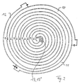
- the microreactor according to Figure 2 has two feeds 10 and 11 and one Exhaust 12 on that in the central area 13 ' Reaction area 13 are arranged and connected to this. It is also conceivable three or more feeds and two or more, if necessary to provide reaction areas arranged one behind the other.
- Such microreactors shown in FIGS. 1a, 1b and 2 can be made from spiral-shaped plate-shaped elements that are built on the end faces are closed, and connections for the inlet and the Have laxation. It is also conceivable that the walls of the inlet and the Discharge and a base plate in one piece from a substrate, for example by microstructuring a polymer and subsequent galvanic impression or by stamping an aluminum plate, manufacture.
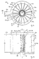
- a microreactor 20 is shown schematically, the one cylindrical central region 30 surrounding, in sectors 31a, b divided and circular in cross-section space 29a.
- Alternating sectors 31a, b here each seventeen, serve as feed 22 or as discharge 23.
- the sectors 31a serving as feed 22 are over the central area 30, which is formed by a free space, with the as Exhaust 23 serving sectors 31b connected.
- the annular space 29a has a variety of sectors, providing good heat exchange between the countercurrent product and feed streams, the radial flow to or from the central region 30.
- the annular space 29a is from an outer annular space 29b, which as Feed distributor 27a is used. For this, this is arranged with a side Main feed 27 b and via slots 29 c with the feed 22 serving sectors 31a.
- the flow directions of the educt and Product flows are indicated as arrows.
- a catalytically active material to provide the central area 30.
- a Heating or cooling device for example a heat exchanger, in the central Arrange area 30.
- FIG. 3b Figure 3a In the lateral cross section of the microreactor 20 shown in FIG. 3b Figure 3a is also the course of the educt and the product flows based on Arrows indicated.
- a reaction region 21 can be seen with one on the Carrier 26 applied catalytic material 25, which via the feed 22, the feed distributor 27a with the side main feed 27b and over the outlet 23 is connected to the main outlet 28.
- the Main outlets 28 are on both end faces of the microreactor 20 above and below both the central area 30, the divided into sectors annular space 29a and the outer annular Space 29b arranged and axially with the serving as a discharge 23 Sectors 31b connected.
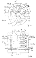
- FIG. 4a shows a microreactor 40 in cross section from above, which has five countercurrent reactor units 41 in the plane shown.
- each Microreactor unit 41 comprises one formed by an inner tube 44 Infeed 43, which in the plane shown is that of the outer tube 42 trained discharge 45 is surrounded and on the closed End of the outer tube 42 located reaction area 46 with this connected is.
- the individual countercurrent reactor units 41 are radial in this way arranged that the fluidically unconnected reaction areas 46 are adjacent in the central region 46 '. In this example it is Area 46 'between the countercurrent reactor units 41 empty, resulting in a Heat transfer to neighboring countercurrent reactor units mainly done by heat radiation. Due to the neighboring arrangement the reaction areas 46 is a heat transfer to the environment minimized.
- the countercurrent reactor units 41 each include an outer one Tube 42 and a coaxially arranged inner tube 44, both tubes have a round cross section.
- the outer tube 42 is at one end closed in a hemisphere.
- the inner tube 44 forms the feed 43, the is surrounded by the discharge 45.
- Die Counterflow reactor units 41 are annular in the interior of the trained discharge collector 49a radially in three planes around the cylindrical central region 46 'arranged.
- the laxative collector 49a connects the individual outlets 45 to the main outlets 49c two end faces of the cylindrical microreactor 40 are arranged.
- the as second outer annular space 47b formed feed manifolds 47 connects the main feeder 48 with the individual feeders 43
- Microreactor units 41 are radially around the central region 46 ' arranged that the reaction areas 46 are adjacent. Because of strong reduced heat radiation loss to the environment is both an effective one Concentration and homogenization of the heat of reaction in the central region 46 'of the microreactor 40 possible. Much of the im The heat of reaction contained in the product stream can be in the feed area 43 and the feed distributor 47 are released to the educt stream.
- the microreactor 40 can consist of three hollow cylinders lying coaxially one inside the other 80a, b, c, for example made of metal foil.
- the outer tubes 42 the countercurrent reactor units 41 represent protuberances of the innermost hollow cylinder 80a.
- the one with the central hollow cylinder 80b connected inner tubes 44 of the countercurrent reactor units are not available in contact with the outer tubes 42 surrounding them, so that bottom This freedom of movement does not affect large temperature differences Lead voltages of the hollow cylinder assembly 80a, b, c.
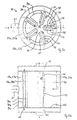
- the microreactor 50 shown schematically in FIGS. 5a, 5b and 5c has five countercurrent reactor units 51, which have a central region 60 ' surrounded such that the reaction areas 60 of the individual countercurrent reactor units 51 are adjacent to each other in the central area 60 '.
- Each countercurrent reactor unit 51 has a feed 56, which in the in Fig. 5a shown level is surrounded by the drain 58, the Connection area between the inlet and outlet of the reaction area 60 forms.
- the Eduktz led by the inlets 56 and the outlets 58.
- Product flows the course of which is indicated by arrows here, run radially to or from the reaction areas 60 located in the central area 60 ′.
- the countercurrent reactor units 51 are of a type as a discharge collector 59a serving circular space 59b surrounded by the Exhausts 58 is connected.
- the discharge collector 59a is in turn from a formed as a second outer annular space 57b Feed distributor 57a surrounded by a laterally on the microreactor 50th arranged main feed 61 the educt flow to the individual Feeders 56 distributed.
- Above and below the cylindrical Microreactor 50 is a main exhaust 62 that axially the products dissipates from the exhaust collector 59a.
- Each feed 56 of a countercurrent reactor unit 51 is divided by two Plate-shaped elements 54, 55 arranged at a distance from one another. These are surrounded by a U-shaped plate-shaped element 53 in such a way that in the two spaces between the elements 54 and 55 and the U-shaped element 53, a channel is formed, which is used as a drain 58 serves.
- the transition area between the feed 56 and the two Exhausts 58, particularly the area of the bend of the U-shaped Element 53, serves as reaction area 60.
- the U-shaped elements 53 of the five countercurrent reactor units 51 corresponding to a single one molded plate-shaped member are formed, the hollow cylinder 90a with U-shaped protuberances.
- Two each one wall one Feeder 56 forming plate-shaped elements 54 of two adjacent ones Counterflow reactor units 51 are made of a plate-shaped element educated. These plate-shaped elements also form the middle ones Hollow cylinder 90b wall between the as exhaust manifold 59a serving annular space 59b and the second outer circular space 57b that serves as a feed manifold 57a.
- the outer Hollow cylinder 90c forms the outer wall of the feed manifold 57a. How from 5c, the hollow cylinders 90a, b, c are with a base plate 63 connected to discharge the product streams from the discharge collector 59a has openings 64 in the main outlet 62. The is accordingly Connection through a cover plate, not shown here, to the one above arranged main drain 62 formed.
- This compact microreactor 50 consists of a few, easy to manufacture elements and is therefore as Inexpensive mass product in many areas, for example in the Fuel cell technology and / or automotive technology, can be used.
- the microreactors have an extremely compact design, in which the Reaction areas in at least one level of educt or product streams are surrounded. By countercurrent flow from the reaction areas emitted heat supplied this again, so that compared to known Microreactors can achieve significantly higher reaction temperatures can. So far, these microreactors have opened another one for Microreactors in particular in the spectrum in question chemical reactions at high temperatures.
Landscapes
- Chemical & Material Sciences (AREA)
- Organic Chemistry (AREA)
- Chemical Kinetics & Catalysis (AREA)
- Physical Or Chemical Processes And Apparatus (AREA)
Abstract
Description
- Fig. 1a
- einen Mikroreaktor mit spiralartiger Anordnung der Zu- und der Abführung im Querschnitt von oben,
- Fig. 1b
- den Mikroreaktor nach Fig. 1a im Querschnitt von der Seite,
- Fig. 2
- einen Mikroreaktor mit spiralartiger Anordnung zweier Zuführungen und einer Abführung im Querschnitt von oben,
- Fig. 3a
- einen Mikroreaktor mit einem in als Zu- bzw. Abführung dienende Sektoren aufgeteilten kreisringförmigen Raum im Querschnitt von oben,
- Fig. 3b
- den Mikroreaktor nach Fig. 3a im Querschnitt von der Seite,
- Fig. 4a
- einen Mikroreaktor mit radial angeordneten, als Gegenstromrohre ausgebildeten Gegenstrom-Reaktoreinheiten im Querschnitt von oben,
- Fig. 4b
- den Mikroreaktor nach Fig. 4a im Querschnitt von der Seite,
- Fig. 5a
- einen Mikroreaktor mit radial angeordneten, aus plattenförmigen Elementen gebildeten Gegenstrom-Reaktoreinheiten im Querschnitt von oben,
- Fig. 5b
- den Mikroreaktor nach Figur 5a im Querschnitt von der Seite,
- Fig. 5c
- den Mikroreaktor nach Fig. 5a und 5b in perspektivischer Darstellung, geschnitten von oben sowie teilweise von der Seite.
- 1
- Mikroreaktor
- 2
- Zuführung
- 3
- Abführung
- 4
- Reaktionsbereich
- 4'
- zentraler Bereich
- 5
- Katalysatormaterial
- 6
- Deckplatte
- 7
- Bodenplatte
- 10
- Zuführung
- 11
- Zuführung
- 12
- Abführung
- 13
- Reaktionsbereich
- 13'
- zentraler Bereich
- 20
- Mikroreaktor
- 21
- Reaktionsbereich
- 22
- Zuführung
- 23
- Abführung
- 24
- Wand
- 25
- Katalysatormaterial
- 26
- Katalysatorträger
- 27a
- Zuführungsverteiler
- 27b
- Hauptzuführung
- 28
- Hauptabführung
- 29a
- kreisringförmiger Raum
- 29b
- äußerer kreisringförmiger Raum
- 29c
- Schlitz
- 30
- zylindrischer zentraler Bereich
- 31a,b
- Sektor
- 40
- Mikroreaktor
- 41
- Gegenstrom-Reaktoreinheit
- 42
- äußeres Rohr
- 43
- Zuführung
- 44
- inneres Rohr
- 45
- Abführung
- 46
- Reaktionsbereich
- 46'
- zentraler Bereich
- 47a
- Zuführungsverteiler
- 47b
- zweiter äußerer kreisringförmiger Raum
- 48
- Hauptzuführung
- 49a
- Abführungssammler
- 49b
- äußerer kreisringtörmiger Raum
- 49c
- Hauptabführung
- 50
- Mikroreaktor
- 51
- Gegenstrom-Reaktoreinheit
- 53
- U-förmig gebogenes plattenförmiges Element
- 54
- plattenförmiges Element
- 55
- plattenförmiges Element
- 56
- Zuführung
- 57a
- Zuführungsverteiler
- 57b
- zweiter äußerer kreisringförmiger Raum
- 58
- Abführung
- 59a
- Abführungssammler
- 59b
- äußerer kreisringförmiger Raum
- 60
- Reaktionsbereich
- 60'
- zentraler Bereich
- 61
- Hauptzuführung
- 62
- Hauptabführung
- 63
- Bodenplatte
- 64
- Öffnung
- 80a,b,c
- Hohlzylinder
- 90a,b,c
- Hohlzylinder
Claims (19)
- Verfahren zur Durchführung chemischer Umsetzungen in einem Mikroreaktor, bei dem ein oder mehrere Eduktströme zu mindestens einem Reaktionsbereich geführt werden, und bei dem ein oder mehrere Produktströme vom Reaktionsbereich im Gegenstrom zu dem bzw. den Eduktströmen und in thermischem Kontakt mit diesem bzw. diesen geführt werden,
dadurch gekennzeichnet, daß
zur Minimierung thermischer Verluste aus dem Reaktionsbereich an die Umgebung der bzw. die Edukt- und Produktströme spiralartig oder radial in mindestens einer Ebene zu bzw. von dem in einem zentralen Bereich des Mikroreaktors angeordneten Reaktionsbereich geführt werden. - Verfahren nach Anspruch 1, dadurch gekennzeichnet, daß mehrere Edukt- und Produktströme jeweils in alternierenden Sektoren eines einen zylindrischen zentralen Bereich umgebenden, im Querschnitt kreisringförmigen Raumes radial zu bzw. von dem zentralen Bereich geführt werden, wobei der zentrale Bereich und/ oder Bereiche der Sektoren als Reaktionsbereich dient bzw. dienen.
- Verfahren nach Anspruch 1, dadurch gekennzeichnet, daß mehrere Edukt- und Produktströme radial zu bzw. von mehreren fluidisch voneinander getrennten und in einem zentralen Bereich des Mikroreaktors und benachbart zueinander liegenden Reaktionsbereichen geführt werden,
wobei jeweils mindestens ein Edukt- und Produktstrom in einer Gegenstrom-Reaktoreinheit geführt werden, die jeweils mindestens einen Reaktionsbereich aufweist. - Verfahren nach Anspruch 3, dadurch gekennzeichnet, daß um die Gegenstrom-Reaktoreinheiten ein Wärmetausch-Medium geleitet wird.
- Verfahren nach einem der Ansprüche 2 bis 4, dadurch gekennzeichnet, daß die Eduktströme und/ oder die Produktströme über einen äußeren kreisringförmigen Raum zu- bzw. abgeführt werden.
- Verfahren nach einem der Ansprüche 1 bis 5, dadurch gekennzeichnet, daß der bzw. die Edukt- und/ oder Produktströme in Kanälen mit einer Breite in mindestens einem Bereich von < 2 mm geführt werden.
- Mikroreaktor (1; 20; 40; 50) zur Durchführung chemischer Umsetzungen mit einer oder mehreren Zuführungen (2; 10, 11; 22; 43; 56) für Edukte und einer oder mehreren Abführungen (3; 12; 23; 45; 58) für Produkte sowie mindestens einem mit der bzw. den Zu- und Abführungen (2, 3; 10, 11, 12; 22, 23; 43, 45; 56, 58) verbundenen Reaktionsbereich (4; 13; 21; 46; 60), wobei die Abführungen im Gegenstrom zu der bzw. den Zuführungen und in thermischem Kontakt mit dieser bzw. diesen angeordnet sind,
dadurch gekennzeichnet, daß
zur Minimierung thermischer Verluste aus dem Reaktionsbereich (4; 13; 21; 46; 60) an die Umgebung die Zuführung (2) und Abführung (3; 12) bzw. die Zuführungen (10, 11; 22; 43; 56) und Abführungen (23; 45; 58) spiralartig oder radial in mindestens einer Ebene um den in einem zentralen Bereich (4'; 13'; 30; 46'; 60') des Mikroreaktors (1; 20; 40; 50) liegenden Reaktionsbereich (4; 13; 21; 46; 60) angeordnet sind. - Mikroreaktor (20) nach Anspruch 7, gekennzeichnet durch einen zylindrischen zentralen Bereich (30), einen diesen umgebenden, in Sektoren (31a,b) aufgeteilten und im Querschnitt kreisringförmigen Raum (29a),
wobei alternierende Sektoren (31a,b) des kreisringförmigen Raumes als Zu- bzw. Abführung (22, 23) dienen,
wobei die als Zuführung (22) dienenden Sektoren (31a) über den zentralen Bereich jeweils mit den als Abführung (23) dienenden Sektoren (31b) verbunden sind, und
wobei der zentrale Bereich (30) und/ oder Bereiche der Sektoren (31a,b) als Reaktionsbereich (21) dient bzw. dienen. - Mikroreaktor (40; 50) nach Anspruch 7, dadurch gekennzeichnet, daß mehrere Zu- und Abführungen (43, 45; 56, 58) radial in mindestens einer Ebene um mehrere fluidisch voneinander getrennte und in einem zentralen Bereich (46'; 60') des Mikroreaktors (40; 50) benachbart zueinander liegende Reaktionsbereiche (46; 60) angeordnet sind, wobei jeweils mindestens eine Zuführung (43; 56) und Abführung (45; 58) sowie mindestens ein Reaktionsbereich (46; 60) in einer Gegenstrom-Reaktoreinheit (41; 51) enthalten sind.
- Mikroreaktor (40) nach Anspruch 9, dadurch gekennzeichnet, daß die Gegenstrom-Reaktoreinheiten (41) jeweils ein Gegenstromrohr, umfassend ein äußeres an einem Ende verschlossenes Rohr (42) und ein koaxial zum äußeren Rohr beabstandetes inneres Rohr (44), aufweisen, wobei das innere Rohr (44) als Zu- oder Abführung (43) und der Bereich zwischen dem äußeren und dem inneren Rohr als Ab- bzw. Zuführung (45) dient, und wobei der Übergangsbereich zwischen der Zu- und der Abführung im Bereich des verschlossenen Endes des äußeren Rohrs als Reaktionsbereich (46) dient.
- Mikroreaktor nach Anspruch 9 oder 10, dadurch gekennzeichnet, daß die Gegenstrom-Reaktoreinheiten in zwei oder mehr Ebenen radial um einen zylindrischen zentralen Bereich angeordnet sind.
- Mikroreaktor nach Anspruch 9 oder 10, dadurch gekennzeichnet, daß die Gegenstrom-Reaktoreinheiten im Raum radial um einen zentralen kugeiförmigen Bereich angeordnet sind.
- Mikroreaktor (50) nach Anspruch 9, dadurch gekennzeichnet, daß die Gegenstrom-Reaktoreinheiten (51) jeweils zwei zueinander beabstandet angeordnete, einen als Zu- oder Abführung (56) dienenden Kanal bildende plattenförmige Elemente (54, 55) sowie ein die beiden plattenförmigen Elemente U-förmig umgebendes und mit diesen jeweils einen als Ab- bzw. Zuführung (58) dienenden Kanal bildendes plattenförmiges Element (53) aufweisen, wobei der Übergangsbereich zwischen der Zu- und der Abführung im Bereich der Biegung des U-förmigen Elementes als Reaktionsbereich (60) dient.
- Mikroreaktor nach einem der Ansprüche 9 bis 13, dadurch gekennzeichnet, daß der die Gegenstrom-Reaktoreinheiten aufweisende zentrale Bereich zum Durchleiten eines Wärmetausch-Mediums ausgebildet ist.
- Mikroreaktor (20; 40; 50) nach einem der Ansprüche 8 bis 14, dadurch gekennzeichnet, daß die Sektoren (31a,b) oder die Gegenstrom-Reaktoreinheiten (41; 51) von einem als Abführungssammter (49a, 59a) oder Zuführungsverteiler (27a) dienenden äußeren im Querschnitt kreisringförmigen Raum (29b; 49b; 59b) umgeben sind, der mit den Abführungen (45; 58) bzw. den Zuführungen (22) in radialer Richtung verbunden ist.
- Mikroreaktor (40; 50) nach Anspruch 15, dadurch gekennzeichnet, daß der äußere, als Abführungssammler (49a; 59a) oder Zuführungsverteiler dienende kreisringförmige Raum (49b; 59b) von einem zweiten äußeren, als Zuführungsverteiler (47a; 57a) bzw. Abführungssammler dienenden im Querschnitt kreisringförmigen Raum (47b; 57b) umgeben ist, der mit den Zuführungen (43; 56) bzw. den Abführungen in radialer Richtung verbunden ist.
- Mikroreaktor (20; 40; 50) nach Anspruch 8 bis 16, gekennzeichnet durch eine oberhalb oder/ und unterhalb des in Sektoren aufgeteilten kreisringförmigen Raumes (29a) oder/ und des ersten oder/ und zweiten äußeren kreisringförmigen Raumes (29b; 49b, 47b; 59b, 57b) angeordnete Hauptabführung (28; 49c; 62) oder Hauptzuführung, die hierzu mit den als Abführung (23) bzw. Zuführung dienenden Sektoren (31b) bzw. dem Abführungssammler (49a; 59a) bzw. dem Zuführungsverteiler in axialer Richtung verbunden ist.
- Mikroreaktor nach einem der Ansprüche 7 bis 17, dadurch gekennzeichnet, daß die Zu- und/ oder Abführungen als Kanäle in mindestens einem Bereich mit einer Breite von < 2 mm ausgebildet sind.
- Mikroreaktor nach einem der Ansprüche 7 bis 18, gekennzeichnet durch gegebenenfalls auf einen Träger aufgebrachtes katalytisch aktives Material im Reaktionsbereich.
Applications Claiming Priority (3)
| Application Number | Priority Date | Filing Date | Title |
|---|---|---|---|
| DE19809139 | 1998-03-04 | ||
| DE19809139 | 1998-03-04 | ||
| PCT/EP1999/001361 WO1999044736A1 (de) | 1998-03-04 | 1999-03-03 | Verfahren zur durchführung chemischer umsetzungen in einem mikroreaktor und solch ein mikroreaktor |
Publications (2)
| Publication Number | Publication Date |
|---|---|
| EP1060014A1 EP1060014A1 (de) | 2000-12-20 |
| EP1060014B1 true EP1060014B1 (de) | 2002-07-03 |
Family
ID=7859623
Family Applications (1)
| Application Number | Title | Priority Date | Filing Date |
|---|---|---|---|
| EP99911729A Expired - Lifetime EP1060014B1 (de) | 1998-03-04 | 1999-03-03 | Verfahren zur durchführung chemischer umsetzungen in einem mikroreaktor und solch ein mikroreaktor |
Country Status (3)
| Country | Link |
|---|---|
| EP (1) | EP1060014B1 (de) |
| DE (2) | DE19909180A1 (de) |
| WO (1) | WO1999044736A1 (de) |
Cited By (1)
| Publication number | Priority date | Publication date | Assignee | Title |
|---|---|---|---|---|
| US11684903B2 (en) | 2018-10-24 | 2023-06-27 | Daniel Shafer | Microscale chemical reactors |
Families Citing this family (14)
| Publication number | Priority date | Publication date | Assignee | Title |
|---|---|---|---|---|
| US6932951B1 (en) | 1999-10-29 | 2005-08-23 | Massachusetts Institute Of Technology | Microfabricated chemical reactor |
| JP4788018B2 (ja) * | 2000-06-08 | 2011-10-05 | トヨタ自動車株式会社 | 燃料電池用燃料補給システムおよび移動体 |
| MXPA03004998A (es) | 2000-12-05 | 2003-09-05 | Texaco Development Corp | Procesador de combustible compacto para producir gas rico en hidrogeno. |
| US6939632B2 (en) | 2001-08-06 | 2005-09-06 | Massachusetts Institute Of Technology | Thermally efficient micromachined device |
| DE10158856A1 (de) * | 2001-11-30 | 2003-06-12 | Volkswagen Ag | Verdampfer für Brennstoffzellenanwendungen |
| US8206666B2 (en) * | 2002-05-21 | 2012-06-26 | Battelle Memorial Institute | Reactors having varying cross-section, methods of making same, and methods of conducting reactions with varying local contact time |
| US7541007B2 (en) * | 2002-12-20 | 2009-06-02 | Lehigh University | Microreactor and method of use to produce hydrogen by methanol reforming |
| JP4432104B2 (ja) | 2003-05-30 | 2010-03-17 | 富士フイルム株式会社 | マイクロリアクター |
| JP2005077219A (ja) | 2003-08-29 | 2005-03-24 | Fuji Photo Film Co Ltd | マイクロデバイスの流体混合反応促進方法及びマイクロデバイス |
| GB0401045D0 (en) * | 2004-01-17 | 2004-02-18 | Univ Sheffield | Fluid-contactor |
| WO2005087360A1 (en) | 2004-03-09 | 2005-09-22 | Intelligent Energy, Inc. | Modular reformer with enhanced heat recuperation |
| US7795359B2 (en) | 2005-03-04 | 2010-09-14 | Novartis Ag | Continuous process for production of polymeric materials |
| US8721981B2 (en) * | 2009-11-30 | 2014-05-13 | General Electric Company | Spiral recuperative heat exchanging system |
| CN115532201A (zh) * | 2018-06-21 | 2022-12-30 | 巴泰勒纪念研究所 | 增强型微通道或中通道装置及其增材制造方法 |
Family Cites Families (3)
| Publication number | Priority date | Publication date | Assignee | Title |
|---|---|---|---|---|
| DE2016614A1 (en) * | 1970-04-08 | 1971-10-21 | Badische Anilin & Soda Fabrik AG, 6700 Ludwigshafen | Exothermic oxidation in catalytic reactor |
| EP0347579B1 (de) * | 1988-06-01 | 1994-03-30 | Daimler-Benz Aerospace Aktiengesellschaft | Vorrichtung mit Träger besonderer Struktur zur Aufnahme, Untersuchung und Behandlung von Proben |
| US5326537A (en) * | 1993-01-29 | 1994-07-05 | Cleary James M | Counterflow catalytic device |
-
1999
- 1999-03-03 DE DE19909180A patent/DE19909180A1/de not_active Ceased
- 1999-03-03 DE DE59901922T patent/DE59901922D1/de not_active Expired - Lifetime
- 1999-03-03 EP EP99911729A patent/EP1060014B1/de not_active Expired - Lifetime
- 1999-03-03 WO PCT/EP1999/001361 patent/WO1999044736A1/de not_active Ceased
Cited By (1)
| Publication number | Priority date | Publication date | Assignee | Title |
|---|---|---|---|---|
| US11684903B2 (en) | 2018-10-24 | 2023-06-27 | Daniel Shafer | Microscale chemical reactors |
Also Published As
| Publication number | Publication date |
|---|---|
| DE59901922D1 (de) | 2002-08-08 |
| DE19909180A1 (de) | 1999-09-09 |
| WO1999044736A1 (de) | 1999-09-10 |
| EP1060014A1 (de) | 2000-12-20 |
Similar Documents
| Publication | Publication Date | Title |
|---|---|---|
| EP0396650B2 (de) | Vorrichtung zur durchführung katalysierter reaktionen | |
| DE19909180A1 (de) | Verfahren zur Durchführung chemischer Umsetzungen in einem Mikroreaktor und solch ein Mikroreaktor | |
| DE69635629T3 (de) | Plattenarchitektur für chemischen Prozess auf Basis von Mikrokomponenten | |
| EP1613424B1 (de) | Mikroreaktor in plattenbauweise mit einem katalysator | |
| EP0885653B1 (de) | Kompakter Festbettreaktor für katalytische Reaktionen mit integriertem Wärmeaustausch | |
| EP3497058B1 (de) | Synthesevorrichtung und verfahren zur herstellung eines produkts | |
| EP1586370B1 (de) | Reaktoranordnung zur Durchführung katalytischer Gasphasenreaktionen | |
| EP0638140B1 (de) | Reaktor zur katalytischen behandlung gasförmiger fluide | |
| DE19947803A1 (de) | Reaktor mit Wärmeübertragerstruktur | |
| EP2349552A1 (de) | Modularer reaktor | |
| EP0687648A1 (de) | Zweistufige Methanol-Reformierung | |
| EP2101900A1 (de) | Reaktor zur durchführung einer kontinuierlichen oxidehydrierung sowie verfahren | |
| EP3802060B1 (de) | Reaktor zur durchführung einer chemischen gleichgewichtsreaktion | |
| EP0484534A1 (de) | Vorrichtung zur durchführung katalytischer wirbelbettverfahren | |
| WO2018029084A1 (de) | Plattenwärmetauscher, synthesevorrichtung und verfahren zur herstellung eines produkts | |
| EP1339485A2 (de) | Mikrostrukturreaktor und verfahren zur durchführung chemischer reaktionen | |
| EP4269345A1 (de) | Verfahren und reaktor zur katalytischen umsetzung eines einsatzstroms | |
| EP1703969B1 (de) | Verfahren und vorrichtung zum mischen wenigstens zweier fluide in einem mikromischreaktor | |
| DE102008025835A1 (de) | Verfahren zur Herstellung von Ethylenoxid | |
| DE102020124610A1 (de) | Mehrfachrohrreaktoren | |
| EP1180496A1 (de) | Vorrichtung zur Zuführung von Edukten zu parallelen Räumen | |
| DE102024138037B3 (de) | Mikrokanalreaktorsystem für katalysatorgestützte chemische Reaktionen | |
| DE10159824A1 (de) | Geordnete Packung für einen Reaktor | |
| LU103102B1 (de) | Konverter für die Ammoniaksynthese | |
| EP4698311A1 (de) | Konverter für die ammoniaksynthese |
Legal Events
| Date | Code | Title | Description |
|---|---|---|---|
| PUAI | Public reference made under article 153(3) epc to a published international application that has entered the european phase |
Free format text: ORIGINAL CODE: 0009012 |
|
| 17P | Request for examination filed |
Effective date: 20000819 |
|
| AK | Designated contracting states |
Kind code of ref document: A1 Designated state(s): CH DE FR GB LI NL |
|
| GRAG | Despatch of communication of intention to grant |
Free format text: ORIGINAL CODE: EPIDOS AGRA |
|
| 17Q | First examination report despatched |
Effective date: 20010717 |
|
| GRAG | Despatch of communication of intention to grant |
Free format text: ORIGINAL CODE: EPIDOS AGRA |
|
| GRAH | Despatch of communication of intention to grant a patent |
Free format text: ORIGINAL CODE: EPIDOS IGRA |
|
| GRAH | Despatch of communication of intention to grant a patent |
Free format text: ORIGINAL CODE: EPIDOS IGRA |
|
| GRAA | (expected) grant |
Free format text: ORIGINAL CODE: 0009210 |
|
| AK | Designated contracting states |
Kind code of ref document: B1 Designated state(s): CH DE FR GB LI NL |
|
| REG | Reference to a national code |
Ref country code: CH Ref legal event code: EP |
|
| REG | Reference to a national code |
Ref country code: CH Ref legal event code: NV Representative=s name: ISLER & PEDRAZZINI AG |
|
| REF | Corresponds to: |
Ref document number: 59901922 Country of ref document: DE Date of ref document: 20020808 |
|
| GBT | Gb: translation of ep patent filed (gb section 77(6)(a)/1977) |
Effective date: 20020819 |
|
| ET | Fr: translation filed | ||
| PGFP | Annual fee paid to national office [announced via postgrant information from national office to epo] |
Ref country code: CH Payment date: 20030218 Year of fee payment: 5 |
|
| PGFP | Annual fee paid to national office [announced via postgrant information from national office to epo] |
Ref country code: GB Payment date: 20030226 Year of fee payment: 5 |
|
| PGFP | Annual fee paid to national office [announced via postgrant information from national office to epo] |
Ref country code: NL Payment date: 20030228 Year of fee payment: 5 |
|
| PGFP | Annual fee paid to national office [announced via postgrant information from national office to epo] |
Ref country code: FR Payment date: 20030314 Year of fee payment: 5 |
|
| PLBE | No opposition filed within time limit |
Free format text: ORIGINAL CODE: 0009261 |
|
| STAA | Information on the status of an ep patent application or granted ep patent |
Free format text: STATUS: NO OPPOSITION FILED WITHIN TIME LIMIT |
|
| 26N | No opposition filed |
Effective date: 20030404 |
|
| PG25 | Lapsed in a contracting state [announced via postgrant information from national office to epo] |
Ref country code: GB Free format text: LAPSE BECAUSE OF NON-PAYMENT OF DUE FEES Effective date: 20040303 |
|
| PG25 | Lapsed in a contracting state [announced via postgrant information from national office to epo] |
Ref country code: LI Free format text: LAPSE BECAUSE OF NON-PAYMENT OF DUE FEES Effective date: 20040331 Ref country code: CH Free format text: LAPSE BECAUSE OF NON-PAYMENT OF DUE FEES Effective date: 20040331 |
|
| PG25 | Lapsed in a contracting state [announced via postgrant information from national office to epo] |
Ref country code: NL Free format text: LAPSE BECAUSE OF NON-PAYMENT OF DUE FEES Effective date: 20041001 |
|
| GBPC | Gb: european patent ceased through non-payment of renewal fee | ||
| REG | Reference to a national code |
Ref country code: CH Ref legal event code: PL |
|
| PG25 | Lapsed in a contracting state [announced via postgrant information from national office to epo] |
Ref country code: FR Free format text: LAPSE BECAUSE OF NON-PAYMENT OF DUE FEES Effective date: 20041130 |
|
| NLV4 | Nl: lapsed or anulled due to non-payment of the annual fee |
Effective date: 20041001 |
|
| REG | Reference to a national code |
Ref country code: FR Ref legal event code: ST |
|
| PGFP | Annual fee paid to national office [announced via postgrant information from national office to epo] |
Ref country code: DE Payment date: 20150324 Year of fee payment: 17 |
|
| REG | Reference to a national code |
Ref country code: DE Ref legal event code: R119 Ref document number: 59901922 Country of ref document: DE |
|
| PG25 | Lapsed in a contracting state [announced via postgrant information from national office to epo] |
Ref country code: DE Free format text: LAPSE BECAUSE OF NON-PAYMENT OF DUE FEES Effective date: 20161001 |