BACKGROUND OF THE INVENTION
The present invention relates to a color proof forming
method and a color proof forming apparatus, and specifically
to a method for forming the color poof by exposing the silver
halide color light-sensitive material by a plurality of light
sources having different wavelengths according to the dot
image data processed by an RIP (Raster Image Processor), and
to the color proof forming apparatus.
There is a case where, when a color printed matter is
formed, the color correction is carried out on the stage of
the document film, and a correction print (color proof) is
formed by using the each color separation dot document film
which is color-separated to a Y (yellow) image, M (magenta)
image, C (cyan) image, and BK (black) image, and before an
actual print film is formed, it is checked whether a layout
of the document film is correct, the color is correct,
characters are correct, and the like, and the finish of the
printed matter is confirmed before the printing.
Recently, the forming of the color proof is conducted
by the DDCP (Direct Digital Color Proof) method. As one
method of the DDCP, according to the dot image data of each
color separation dot document, a method by which a light spot
composed of the combination of a plurality of light rays with
different wavelengths, for example, such as R, G and B, is
exposed on the silver halide light-sensitive material, and
each dot of Y, M, C and K is colored, is used.
However, recently, by the spread of DTP (Desk Top
Publishing), or the like, an operation in which an image
inputted by a scanner is image-edited and paginated by the
software of a computer, comes into common use, and the
edition by the full digital system also comes into common
use.
In such the process, for the purpose of more
efficiency, an image setter output to directly output the
page-edited image data onto the film, a CTP (Computer to
Plate) output to directly conduct the image recording on the
print film, and further, or a CTC (Computer to Cylinder) to
directly image-record onto the print film wound around a
cylinder of the printing machine, is conducted.
In this case, there is a problem that the uselessness
of the film or the print film is generated, or the
superfluous operations increase, when a film output or print
film output is conducted once only for the correction
confirmation, and the print correction, or the correction by
the other correction material is conducted.
Accordingly, specifically, in the process in which such
the fully digitized image formation and the edition are
conducted by the computer, a system by which the color image
output is directly conducted, which is called the DDCP
(Direct Digital Color Proof) or the DCP (Digital Color
Proof), is required.
This DDCP forms a color proof to reproduce the output
object shown by the digital image processed by the computer,
and confirms its pattern, image tone, and the sentence and
characters, before recording onto the print making film from
the digital image data processed by the computer by the image
setter, or the like, or conducting the final printing
operation for directly forming the print film by the CTP, or
directly recording the image onto the print film wound around
the cylinder of the printing machine by the CTC.
Further, in a process of proofreading in such the
printing process, the proof is mainly formed and used for the
following three purposes: (1) a proof for confirming a miss
of the inside of the operation site, (2) a proof to be
submitted to an ordering person, or a designer for confirming
the finish, and (3) a print sample to be submitted to the
chief of the printing machine as the sample of the final
printed matter.
In this case, in the above-mentioned proof (1) and a
part of the proof (2), there is a case that, for the needs of
the reduction of the time limit of the delivery, and the cost
reduction, the proofreading material by which the dot image
can not be reproduced, that is, the proofreading by a
sublimation transfer system, is conducted, or a case that the
output matter such as the inkjet, or electrophotography is
mainly used as the proof for the page-effect confirmation,
however, for the confirmation of the reproducibility of a
highlight portion or the confirmation of fine details, or the
confirmation of the unsuitable interference fringes of the
dot image, called moire, at the time of printing, the actual
situation is that a proof by which the printing dot is
faithfully reproduced, is strongly required.
For such the needs, recently, a DDCP in which, by using
a high power heat mode laser, the image exposure is conducted
on the sublimation transfer recording material or the heat
sensitive recording material, and these are transferred onto
the printing paper, begins to spread, however, in these
systems, the cost of the laser head is high, the cost of the
machine is high, and further, as the material, because a lot
of color image forming sheets are used, the cost is high, and
further, the process from the image exposure to transferring,
is necessary for the number of colors, and a long period of
time is required, which is a problem, and there is a problem
that application for all businesses, and formation of many
duplications as in the conventional printing proofreading,
are difficult in the cost and the time.
Accordingly, as an apparatus to form such a color
proof, an image recording apparatus, which has a drum
provided with a plurality of holes penetrating from the outer
peripheral surface to the inside, and a rotation driving
mechanism to rotate the drum, and which exposes corresponding
to the digital image signal, and records the dot image while
rotating the drum by the rotation driving mechanism, under
the condition that the light-sensitive material is being held
on the drum, is proposed.
Incidentally, recently, the DTP advances, and the image
pattern can be freely superimposed by the image process
software by the personal computer. Accordingly, although the
user is not conscious, a black image in which a black image
is superimposed with other color images, also increases.
In this case, on the display of the personal computer,
the entire region in which the black image is superimposed
with other color images, looks black. Accordingly, the user
is not conscious of the situation that other color images,
which are actually unnecessary, are superimposed on the black
image.
Further, also in the DDCP, because an image in which
the black image and other color images are superimposed with
each other, is expressed by the black color, and entire the
superimposed region looks black, the situation that the black
image and the other color images are superimposed with each
other, is not perceived.
However, when the printing is actually conducted,
because an appearance is different in a portion of only the
black image, and a portion in which the black image and the
other color images are superimposed with each other
(hereinafter, in this specification, called a "black overlap
print"), it is perceived at first that the unnecessary other
color images are overlapped with the black image. That is,
the miss in the image processing stage is perceived at first
at the time of the printing, and a large uselessness is
generated in the operation time or the each kind of material.
SUMMARY OF THE INVENTION
The present invention is attained to solve the above
problems, and an object of the present invention is to
realize a color proof forming method to form a color proof by
which a portion of only the black image can be discriminated
from a portion of the black overlap print, and a color proof
forming apparatus.
Structures (1) to (5) to attain the above object are as
follows.
BRIEF DESCRIPTION OF THE DRAWINGS
Fig. 1 is a view showing an example of an LUT in an
apparatus of an example of an embodiment of the present
invention.
Fig. 2 is a perspective view of an appearance of the
apparatus of an example of the embodiment of the present
invention.
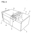
Fig. 3 is a perspective view of an appearance of the
apparatus of an example of the embodiment of the present
invention.
Fig. 4 is a typical view showing the internal structure
of the apparatus of an example of the embodiment of the
present invention.
Fig. 5 is a typical view showing a portion of the
internal structure of the apparatus of an example of the
embodiment of the present invention.
Fig. 6 is a typical view showing a portion of the
internal structure of the apparatus of an example of the
embodiment of the present invention.
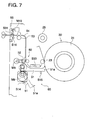
Fig. 7 is a typical view showing a portion of the
internal structure of the apparatus of an example of the
embodiment of the present invention.
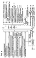
Fig. 8 is a block diagram showing the electric
structure of the apparatus of an example of the embodiment of
the present invention.
Fig. 9 is a characteristic view showing an example of
the relationship between an exposure amount and the density
of the light-sensitive material in the apparatus of an
example of the embodiment of the present invention.
Fig. 10 is a view showing an example of the LUT in the
conventional apparatus.
Fig. 11 is an illustration showing another example of
the LUT of the embodiment of the present invention.
Fig. 12 is a characteristic view showing an example of
the relationship between the exposure amount and the density
of the light-sensitive material in the apparatus of an
example of the embodiment of the present invention.
Fig. 13 is a flow chart showing an operation of the
apparatus of an example of the embodiment of the present
invention.
Fig. 14 is a flow chart showing an operation of the
apparatus of an example of the embodiment of the present
invention.
Fig. 15 is a flow chart showing an operation of the
apparatus of an example of the embodiment of the present
invention.
Fig. 16 is a flow chart showing an operation of the
apparatus of an example of the embodiment of the present
invention.
Fig. 17 is a flow chart showing an operation of the
apparatus of an example of the embodiment of the present
invention.
Fig. 18 is a flow chart showing an operation of the
apparatus of an example of the embodiment of the present
invention.
DETAILED DESCRIPTION OF THE PREFERRED EMBODIMENT
Referring to the drawings, an embodiment of the present
invention will be described below. Incidentally, the present
invention is not limited to the embodiment, which will be
described below. Further, there is a description in which
the meaning of terms are described, however, this is the
description which describes the meaning of terms strictly in
the embodiment, and the meaning of terms of the present
invention is not limited to this description.
(Structure)
Initially, the overall structure of an image recording
apparatus to which the embodiment of the present invention is
applied, will be described.
The image recording apparatus of the present embodiment
is an apparatus to obtain a color proof for obtaining a proof
to previously confirm the finish of the printed matter from a
digital image signal. Specifically, this is an apparatus by
which, when the color printed matter is formed, before the
printed film is formed from the digital image signal, a color
proof to simulate an image obtained by printing by using the
printed film which is formed from the digital image signal,
is formed from the digital image signal, and the existence of
an error, such as, for example, whether there is an error of
a layout, color, characters, etc., in the image shown by the
digital image signal, is checked, and in order to previously
confirm the finish of the printed matter, the color proof is
formed.
Further, in the image recording apparatus of the
present embodiment, as the light-sensitive material, a roll
shaped silver halide color photographic light-sensitive
material is set, and in the exposure section, after it is cut
into the sheet-like material, it is exposed corresponding to
the digital image signal, and then, it is development-processed
in a development processing section, and the color
proof is formed.
In Fig. 2 to Fig. 4, the color proof forming apparatus
is shown. Fig. 2 is a perspective view of the color proof
forming apparatus, Fig. 3 is a perspective view of the color
proof forming apparatus in the condition in which a feed
cover is opened, and Fig. 4 is a typical view of the internal
structure of the color proof forming apparatus.
In an apparatus main body 2 of the color proof forming
apparatus 1, an exposure unit 3 and a development processing
unit 4 are provided. In the exposure unit 3, an upper
surface panel 5, and a front surface panel 6 are provided so
that these can be opened and closed, and the maintenance
operation can be conducted from the upper surface and front
surface side. On the upper portion of the exposure unit 3, a
sheet loading section 7 is located on the development section
side, and an operation section 8 is located on the front
surface side of the apparatus main body 2 on the front side
of the sheet loading section 7. In the sheet loading section
7, a feed cover 9 is provided so that it can be opened and
closed, and a cartridge 10 in which the light-sensitive
material (hereinafter, called paper or light-sensitive
material) is accommodated, can be set by the feed cover 9. A
liquid crystal panel 11 and a touch panel 12 are provided in
the operation section 8.
An upper surface panel 13 and a replenishment panel 14
are provided to the development processing unit 4 so that
these panels can be opened and closed, and the maintenance
operation is carried out from the upper surface side, and the
replenishment of a processing solution is carried out from
the front surface side. A sheet delivery section 15 is
provided on the side portion of the development processing
unit 4, and the processed light-sensitive material is
delivered to the sheet delivery section 15.
Fig. 4 is a view showing a schematic structure of the
color proof forming apparatus. In the exposure unit 3, a
sheet feed section 20, a primary scanning section 30, a sub-scanning
section 40, a sheet delivery section 50, and an
accumulator section 60 are provided. In the sheet feed
section 20, feed rollers 21a, 21b, a cutter 22, and a drum
feed roller 23 are provided. The light-sensitive material is
pulled from the cartridge 10 by the feed rollers 21a and 21b,
cut into a predetermined length by the cutter 22, and fed to
the primary scanning section 30 through the drum feed roller
23.
A drum 31 is rotatably provided in the primary scanning
section 30, and the light-sensitive material is attracted to
the outer surface of the drum 31, and integrally rotated. An
optical unit 32 is arranged opposite to the drum 31, and the
optical unit 32 can move in parallel with the drum axis by
the sub-scanning section 40. The optical unit 32 receives
the digital image signal and exposes the light-sensitive
material attracted onto drum 31 by an LED light emitting
beam, and writes the image onto the light-sensitive material.
The sheet delivery section 50 is provided with a
separation guide 51, and the light-sensitive material onto
which writing is completed, is separated from the drum 31 by
the separation guide 51 and sent to the development
processing unit 4. At this time, when the conveyance speed
of the development processing unit 4 is slower than the sheet
delivery speed of the exposure unit 3, the light-sensitive
material is sent to the accumulator section 60 while the
sheet delivery speed is high, and the light-sensitive
material is accumulated so that it hangs down on the
accumulator section 60, and is in timed relationship with the
conveyance timing of the development processing unit 4, so
that the processing capacity of the exposure unit 3 is not
lowered.
The development processing unit 4 is provided with the
second exposure section 41 (hereinafter, an example of the
reversal exposure direct positive light-sensitive material
will be described), the development section 42, fixing
section 43, stabilization section 44, and drying section 45.
A portion of the light-sensitive material which is not
exposed by the exposure unit 3 forms a false-image by the
second exposure section 41, and the light-sensitive material
which is second-exposed, is conveyed to the development
section 42, fixing section 43 and stabilization section 44,
and development processed, and the processed light-sensitive
material is dried by the drying section 45, and sent to the
sheet delivery section 15.
Next, the structure of each section of the color proof
forming apparatus will be detailed by using Fig. 5 to Fig. 7.
Fig. 5 is a side view showing a paper loading section and a
paper feed section, Fig. 6 is a plan view showing the primary
scanning section and the sub-scanning section, and Fig. 7 is
a side view showing a sheet delivery section and an
accumulator section.
The paper loading section 7 is provided with the feed
cover 9 on the upper surface panel 5 so that it can be opened
and closed, and under the condition that the feed cover 9 is
opened, a cartridge 10 is set to a loading port 70. Under
the condition that the cartridge 10 is set, the feed cover 9
is closed, and the feed cover 9 is locked by a lock mechanism
71. The lock mechanism 71 is operated by a cover lock motor
M1. The feed cover 9 is provided with a cartridge presence
sensor S1, and a closing cover sensor S2 and a cover lock
detecting sensor S3 are provided in the loading port 70. The
cartridge 10 is set at the position of the feed rollers 21a
and 21b of the feed section 20 under the condition that a
leading edge portion of the light-sensitive material is
pulled out by a predetermined length.
A paper end sensor S4 is provided in the feed section
20 between the feed rollers 21a, 21b and the cartridge 10,
and the trailing edge of the light-sensitive material pulled
from the cartridge 10 is detected by the paper end sensor S4.
A position of one feed roller 21a is fixed, and the other
feed roller 21b can be moved by a roller movement mechanism
24, and the feed roller 21b is moved to a stand-by position
for preventing the paper wrinkle from being generated due to
the pressure-contact of the roller, except for the time
period during the paper conveyance operation. The roller
movement mechanism 24 is operated by a feed roller pressure
release motor M2.
During the conveyance of the light-sensitive material,
the feed roller 21b is moved to the conveyance position, and
the light-sensitive material is pressure-contacted between
the feed rollers 21a and 21b which are opposite to each
other. The position of the feed roller 21b is detected by a
feed roller pressure-contact position detecting sensor S5 and
a feed roller release position detecting sensor S6. The feed
roller 21a is operated by the feed motor M3.
The cutter 22 is operated by a cutter motor M20. An
encoder roller 25 and a guide 26 are provided between the
cutter 22 and a drum feed roller 23. The encoder roller 25
sends the light-sensitive material by the rotation, and
detects the feed amount of the light-sensitive material.
The drum feed roller 23 can be moved to the contact
pressure position and the release position by the roller
movement mechanism 27. This drum feed roller 23 is driven by
the drum feed motor M4. The position of the drum feed roller
23 is detected by the drum feed roller pressure position
detecting sensor S7 and the drum feed roller release position
detecting sensor S8, which are not shown in the drawing. The
roller movement mechanism 27 is operated by the drum feed
roller pressure release motor M5.
Shaft portions 31a and 31b of both ends of the drum 31
of the primary scanning section 30 are pivotally supported
rotatably by support bases 34a and 34b through bearings 33a
and 33b. A drive pulley 35a is provided on one shaft portion
31a of the drum 31, and the drive pulley 35a is connected to
an output pulley 35b of a drum rotation motor M6 with a belt
36, and the drum 31 is rotated by the drive of the drum
rotation motor M6. Further, on one shaft portion 31a of the
drum 31, a rotary encoder 37 is provided, and the rotary
encoder 37 outputs a rotation pulse, and is used for the
pixel clock control which is in timed relationship with the
drum rotation.
The other shaft portion 31b of the drum 31 is connected
to a suction blower P1. The drum 31 is formed of a hollow
body, and suction holes 31c are formed on the drum surface,
and the inside of the drum 31 is pressure-reduced by the
drive of the suction blower P1 and the light-sensitive
material is attracted onto the surface of the drum 31.
A red LED unit 320, green LED unit 321, and blue LED
unit 322 are arranged in the optical unit 32. The light beam
from the red LED unit 320 and green LED unit 321 exposes
through mirrors 325 and 326, further, the light beam from the
blue LED unit 322 exposes through a mirror 327, an image onto
the light-sensitive material P on the drum 31 from a
condenser lens 331. An exposure shutter 332 opens and closes
the optical path at the time of the exposure start/end by
being opened and closed by an exposure solenoid 333.
The optical unit 32 is fixed to a movement belt 340,
and is provided so that it can be moved in parallel with the
drum axis by being guided by a pair of guide rails 341 and
342. The movement belt 340 is wound around a pair of
pulleys 343 and 344, and one pulley 344 is connected to an
output shaft 345 of a sub-scanning motor M7, and the optical
unit 32 is moved in parallel with the drum axis by the drive
of the sub-scanning motor M7.
In the drum axis direction of the optical unit 32, a
sub-scanning reference position detecting sensor S11, a sub-scanning
writing position detecting sensor S12, and a sub-scanning
over run position detecting sensor S13 are arranged.
The optical unit 32 is stopped by the sub-scanning reference
position detection of the sub-scanning reference position
detecting sensor S11, and the sub-scanning is started from
this sub-scanning reference position, and the sub-scanning is
stopped by the movement amount corresponding to the image
size, and the optical unit 32 is moved to the sub-scanning
reference position and returned.
In the sheet delivery section 50, conveyance rollers
52, 53, a conveyance guide 54, a separation guide 51 and an
exit shutter 55 are arranged. The conveyance rollers 52 and
53 are driven being interlocked with each other by a
conveyance motor M8. The separation guide 51 is moved upward
and downward by a separation guide up-down motor M9, and at
the upper position, a claw portion 51a of the separation
guide 51 separates the light-sensitive material of the drum,
and at the lower position, the light-sensitive material is
accumulated. The open and close of the separation guide 51
are detected by a separation guide opening sensor S14, and a
separation guide closing sensor S15. A separation jam
detecting sensor S30 is provided on the sheet delivery path
of the light-sensitive material.
The exit shutter 55 is opened and closed by an exit
shutter motor M10. The open and close of the exit shutter 55
is detected by an exit shutter open detecting sensor S16.
The exit shutter 55 determines the delivery timing of the
light-sensitive material, and opens the exit shutter 55 at
the predetermined timing, and sends the light-sensitive
material to the development processing unit 4. Further, an
exit sensor S31 to detect that the light-sensitive material
is sent to the development processing unit 4, is provided.
The accumulator section 60 is arranged at the lower
position of the sheet delivery section 50, and when the
separation guide 51 is moved downward, the light-sensitive
material hangs down in the accumulator section 60. According
to this, when the light-sensitive material is accumulated at
the high speed (to the development conveyance speed), the
light-sensitive material can be sent to the development
processing unit 4 without being damaged.
In Fig. 8, the electrical structure of the present
apparatus will be shown as a block diagram. As shown in this
Fig. 8, the control section 100 has a CPU 101, RAM 102, and
ROM 103, and is connected to each sensor and a group of
actuators through I/ O ports 104 and 105, and controls the
group of actuators according to the information from each
sensor.
As sensors, the cartridge presence sensor S1, closing
cover sensor S2, cover lock detecting sensor S3, paper end
sensor S4, feed roller pressure position detecting sensor S5,
feed roller release position detecting sensor S6, drum feed
roller pressure position detecting sensor S7, drum feed
roller release position detecting sensor S8, paper leading
edge reference position sensor S9, paper feeding amount
detecting sensor S10, rotary encoder 37, sub-scanning
reference position detecting sensor S11, sub-scanning writing
position detecting sensor S12, sub-scanning over-run position
detecting sensor S13, separation guide opening sensor S14,
separation guide closing sensor S15, exit shutter opening
detecting sensor S16, and separation jam detecting sensor S30
are connected. Further, the exit sensor S31 which is not
shown in this drawing, is also connected.
As the group of actuators, a cover lock motor M1, feed
roller pressure releasing motor M2, feed motor M3, cutter
motor M20, drum feed motor M4, drum feed roller pressure
release motor M5, drum rotation motor M6, sub-scanning motor
M7, exposure shutter solenoid 333, conveyance motor M8,
separation guide up-down motor M9, and exit shutter motor M10
are connected, and respectively driven through drivers D1,
D2, D3, D11, D5, D4, D6, D7, D333, D8, D9, and D10.
Further, in the operation section 8, a liquid crystal
panel 11 is controlled by a driver D20, and displays the
operation condition of the color proof forming apparatus.
Further, a command by the operation from a touch panel 12 is
sent to the CPU 101 as the digital information by an A/D
converter 120.
From an RIP 200 connected to the outside, the digital
image information is sent to a data buffer 204 through an
image data I/F section 201. On the one hand, the digital
image information is made to be in timed relationship with an
output signal from a PLL 202 according to the light-sensitive
material feeding information from the rotary encoder 37, and
is given to drivers D320, D321, and D322, from the data
buffer 205 through a LUT (Look Up Table) 205 and D/A
converter sections 206 - 208 by a dot clock of a dot clock
generation section 203, and by these drivers D320, D321 and
D322, the red LED unit 320, green LED unit 321, and blue LED
unit 322 are respectively driven.
Herein, the dot image data of each color (Y, M, C, BK)
formed by the RIP 200 is transferred to the image data I/F
section 201, and data-converted from the RIP format to the
exposure format, and accumulated in the data buffer 204.
After the image data for one sheet is accumulated in the data
buffer 204, the all colors are simultaneously exposed.
In this case, the Y, M, C, BK print data of the printed
matter, which is corresponding to the LED light emission
minimum driven dot (pixel) at the time of exposure, is given
as 16 combinations as shown in Fig. 1, and as shown in Fig.
1, it is converted into combinations of the LED light
emission intensity of R, G, B specified by the LUT 205, and
the exposure is conducted in a pixel unit in which the lED
light emission of 3 wavelengths are overlapped.
Herein, the LUT 205 is characterized in that it forms
the exposure data different in the image data in which the
black color and other colors are overlapped with each other,
and in the image data of only the black color. That is, in
the present embodiment, the exposure data different in the
image data in which the black color and other colors are
overlapped with each other, and in the image data of only the
black color, is formed and the exposure is conducted, and the
light-sensitive material is exposed in the different
conditions. According to this, a color proof by which a
portion of only the black color, and a portion of the black
overlap print can be discriminated, can be formed.
Fig. 1 shows the content of the table of the printing
data and the light emission intensity of the LED unit when
the direct positive light-sensitive material is used.
Incidentally, the relationship between the light emission
amount of the LED unit and the density of the light-sensitive
material obtained by the exposure, is defined as shown in
Fig. 9.
Incidentally, the LUT 205 stores the data regulating
the correspondence with the reference colors of the print,
that is, Y (yellow), M (magenta), C (cyan), B(blue), G
(green), R (red), BK (black), GY (gray), and W (white), and
the intensity of the component of the light of the light
source by which these reference colors are exposed onto the
light-sensitive material, that is, R (red), G (green), B
(blue).
Herein, conventionally, the drive of the LED unit is
according to a digital modulation of only ON and OFF, and the
LED light emission intensity is either one of 0 % (the LED
unit does not emit the light), or 100 % (the LED unit emits
the light at an optimum light emission amount to the light-sensitive
material)(refer to Fig. 10). However, in that
case, the kind of the Y, M, C, BK coloring density of the
light-sensitive material is fixed, and a portion of only the
black and a portion of the black overlap print are exposed so
that all of these portions becomes black (BK) (Fig. 10 (1)).
In contrast to that, in the present embodiment, not
only 0 % and 100 % of the light emission amount in Fig. 9,
but also 5 % and 10 % are used. When BK is reproduced, each
LED unit respectively emits the light by 5 %, and the density
of D5 which is slightly thinner than the conventional Dmax,
is obtained for each color. Further, for other colors which
are overlapped with the BK, 5 % light emission, not the
conventional 0 %, is conducted so that the weight becomes
clear (Fig. 1 (1)). Incidentally, in this case, when all of
Y, M, and C are overlapped with the BK, the light emission
amount is made to 0 %, and the maximum density is obtained.
Further, at the same time as the density is lowered as
described above, the reproduction of the color not including
the BK, is conducted so that each LED unit respectively emits
the light by 10 %, which is not the conventional 0 % for
each color, and the density of D10 which is slightly thinner
then conventional Dmax, is obtained for each color (Fig. 1
(2)).
When the exposure data is formed from the image data by
using the above-described LUT 205, for the image data in
which the BK is overlapped with other colors (Y, M, C, R, G,
B, GY), the higher density black color than in the case of
the image data of only the BK, can be generated on the color
light-sensitive material. Further, it can also be
discriminated with which color the BK is overlapped.
Fig. 11 shows the table content of the print data and
the light emission intensity of the LED unit, when the
negative light-sensitive material is used. Incidentally, the
relationship between the light emission amount of the LED
unit and the density of the light-sensitive material obtained
by the exposure, is defined as shown in Fig. 12.
Also in the case of this negative light-sensitive
material, conventionally, the drive of the LED unit is
according to the digital modulation of only ON and OFF, and
the LED light emission intensity is either one of 0 % (the
LED unit does not emit the light), or 100 % (the LED unit
emits the light at an optimum light emission amount to the
light-sensitive material). The kind of the Y, M, C, BK
coloring density of the light-sensitive material is fixed,
and a portion of only the black image and a portion of the
black overlap print are exposed so that all of these portions
becomes black image (BK).
In contrast to that, in the present embodiment, not
only 0 % and 100 % of the light emission amount in Fig. 12,
but also 90 % and 95 % are used. When BK is reproduced, each
LED unit respectively emits the light by 95 %, and the
density of D95 which is slightly lighter than the
conventional Dmax, is obtained for each color. Further, for
other colors which are overlapped with the BK, 100 % light
emission is conducted so that the weight becomes clear (Fig.
11 (1)). Incidentally, in this case, when all of Y, M, and C
are overlapped with the BK, the light emission amount is made
to 100 % for each color, and the maximum density is obtained.
Further, at the same time as the density is lowered as
described above, the reproduction of the color which does not
include the BK, is conducted so that each LED unit
respectively emits the light by 90 %, which is not the
conventional 100 % for each color, and the density of D90
which is slightly lighter than conventional Dmax, is obtained
for each color (Fig. 11 (2)).
When the exposure data is formed from the image data by
using the above-described LUT 205, for the image data in
which the BK color is overlapped with other colors (Y, M, C,
R, G, B, GY), the higher density black color than in the case
of the image data of only the BK color, can be generated on
the color light-sensitive material. Further, it can also be
discriminated with which color the BK color is overlapped.
Incidentally, in the above description, when the light
emission intensity is controlled to 5 %, 10 %, 90 %, 95 %,
except for 0 % and 100 %, the exposure is conducted so that
the weight of other colors to the BK color can be known,
however, the numeric values to regulate the light emission
intensity are not limited to the values shown here. Further,
corresponding to the color of the ink, the values of 0 %, 5
%, 10 %, 90 %, 95 %, 100 %, may be changed for each color, or
for each case.
Further, the density of the portion in which the BK
color is overlapped with other colors, is set to be more
increased than the density of the portion of only the BK
color, however, this may be reversely set.
Incidentally, in the case where the positive light-sensitive
material using the panchromatic emulsion is used,
when the BK color is overlapped with other colors, by setting
the light emission amount which is conventionally 0 %, to 5
%, the photosensitive layer of the panchromatic emulsion does
not react, but the photosensitive light of the color
corresponding to the exposure reacts to it, and the density
is lowered. According also to this, the weight of the BK
color and other colors can be distinctly shown.
Further, in the above embodiment, the apparatus in
which the image recording is conducted by the dot image data,
is described as an example, however, the present invention
can be applied to an image recording apparatus in which the
exposure is conducted by the light source corresponding to a
plurality of colors, without being limited to the dot image
data.
(Operation)
Herein, operations of an image recording apparatus to
which the embodiment of the present invention is applied,
will be described.
Referring to Fig. 13 to Fig. 18, operations of the
color proof forming apparatus will be described below. Fig.
13 is a main flow chart of the operations of the color proof
forming apparatus, Fig. 14 and Fig. 15 are flow charts of the
sheet feed processing of the color proof forming apparatus,
Fig. 16 is a flow chart of the print processing of the color
proof forming apparatus, Fig. 17 is a flow chart of the sheet
delivery processing of the color proof forming apparatus, and
Fig. 18 is a flow chart of the delivery processing of the
color proof forming apparatus.
Initially, a main operation of the color proof forming
apparatus will be described. In a main flow chart of the
operation of the color proof forming apparatus in Fig. 13,
when the main switch is turned ON in step a1, the initial
setting of the apparatus is conducted in step b1, further,
the initial setting of each mechanism portion is conducted in
step c1, and when an error occurs herein, the function stops.
When the initial setting is completed, an idling
operation is conducted, and a remote processing can be
conducted (step d1). The condition setting can be conducted
by the operation of the menu key of the touch panel 12 of the
operation section 8 during this idling operation (step e1),
and when this condition setting is conducted, the local
processing can be conducted. When the condition setting is
not conducted by the operation of the menu key of the touch
panel 12, the remote processing by which the output image
from the RIP is received and the print of the received image
data is conducted, is carried out.
Further, when the light-sensitive material becomes
insufficient and replenishment is conducted during the idling
operation, the sheet feed cover 9 is opened, the cartridge 10
is set, the sheet feed cover 9 is closed, and the sheet feed
processing to cut a fogged portion of the leading edge of the
light-sensitive material is conducted, and the operation
returns to the idling operation (step f1), however, when an
error occurs in the sheet feed processing to cut the fogged
portion of the leading edge of the light-sensitive material,
the function is stopped.
The writing operation consists of the sheet feeding
(step g1), printing (step h1), and sheet delivery (step i1),
and when this writing processing is completed, the next
light-sensitive material can be fed (step j1).
Next, the sheet feed processing of the color proof
forming apparatus will be described. In the flow chart of
the sheet feed processing of the color proof forming
apparatus in Fig. 14, the judgment of the existence of the
cartridge 10 is conducted in step a2, and when the cartridge
10 does not exist, the error processing is conducted (step
b2).
When the cartridge 10 exists, the trailing edge of the
light-sensitive material is detected according to the
detection signal from the paper end sensor S4 (step c2), and
when the trailing edge of the light-sensitive material is
detected, the error processing is conducted (step b2).
When the trailing edge of the light-sensitive material
is not detected, the sheet feed cover 9 is locked (step d2),
the feed roller 21b is brought into pressure-contact (step
e2), and further, the drum feed roller 27 is brought into
pressure-contact (step f2). Then, the excitation of the drum
rotation motor M6 is turned OFF, and the drum 31 is made to
be rotatable (step g2), the feed motor M3 is rotated, and the
light-sensitive material is fed by the feed rollers 21a and
21b (step h2).
The leading edge portion of the light-sensitive
material is detected by the paper leading edge reference
position sensor S9 (step i2), and when the leading edge is
detected, the measurement of the length of the light-sensitive
material is started by the rotation of the encoder
roller 25 using the detection as the reference (step j2), and
the light-sensitive material is fed, and the length of light-sensitive
material is counted from the feed amount of the
light-sensitive material, and when it becomes a predetermined
length (step k2), the feed motor M3 is turned OFF (step 12),
and the waiting for stabilization for a predetermined period
of time is conducted (step m2), and the pressure-contact of
the feed roller 21b is released (step m2), and the light-sensitive
material is made so that it can be conveyed, by the
rotation of the drum feed roller 23 and the drum 31.
In the flow chart of the sheet feed processing of the
color proof forming apparatus in Fig. 15, the paper suction
blower P1 is turned ON in step a3, and its stabilization is
waited (step b3), and after the stabilization, the drum feed
motor M4 is turned ON (step c3). Thereby, the paper is wound
around the drum 31 while being sucked to it.
The paper length measurement is started in step d3, and
after a predetermined length is pulled out (step e3), the
drum feed motor M4 is turned OFF in step f3. The feed roller
21b is brought into pressure-contact in step g3, and the
paper cut is conducted in step h3, the drum teed motor M4 is
turned ON in step i3, and the pressure-contact of the feed
rollers 21a and 21b is released in step j3.
After the waiting of the completion of the paper
winding around the drum in step k3, the drum feed motor M4 is
turned OFF in step 13, and the pressure-contact of the drum
feed an delivery roller 23 is released in step m3.
In the flow chart of the print processing of the color
proof forming apparatus in Fig. 16, the drum rotation motor
M6 is turned ON in step a4, and the stabilization of the
rotation of the drum 31 is waited (step b4), the sub-scanning
motor M7 is turned ON (step c4), the exposure shutter 332 is
turned ON (step d4), and the optical unit 32 is moved in the
direction of the drum axis and sub-scanning is conducted, and
the sub-scanning writing position is detected in step e4,
and the image data is outputted (step f4).
At this time, the red LED unit 320, green LED unit 321,
and blue LED unit 322 respectively emit the light according
to the LUT data of the set channel, and expose the image
having the color corresponding to the color of the ink at the
time of the print and/or the color of the print sheet.
Incidentally, in this case, for the image data in which
the BK color and other colors (Y, M, C, R, G, B, GY) are
overlapped with each other, the exposure data is made so that
the higher density or lower density black color than in the
case of the image data of only the BK color is generated on
the color light-sensitive material.
When the writing of the image data is completed in step
g4, the drum rotation motor M6 is turned OFF (step h4), the
sub-scanning motor M7 is turned OFF (step i4), and optical
unit 32 is moved to the home position (step j4).
Then, the drum feed roller 23 is brought into pressure-contact
with the drum 31 in step k4, the excitation of the
drum rotation motor M6 is turned OFF (step 14), and the drum
31 is moved to the home position by the rotation of the drum
feed roller 23 (step m4).
In the flow chart of the sheet delivery processing of
the color proof forming apparatus in Fig. 17, the separation
guide 51 is closed and set to the separation position in step
a5, and the exit shutter 55 to the development processing
unit 4 is opened (step b5), and it is brought into pressure-contact
with the drum feed roller 23 (step c5).
The drum feed motor M4 is turned ON in step d5 and the
drum feed roller 23 is rotated, and the conveyance motor M8
is turned ON, and the light-sensitive material is conveyed at
high speed and fed (step e5). By the separation jam
detecting sensor S30, it is judged whether the separation jam
of the light-sensitive material is caused or not (step f5),
and when no separation jam is caused, the drive of the
suction blower P1 is stopped and the suction of the light-sensitive
material is released (step g5).
In step h5, the delivery of the light-sensitive
material is detected by the exit sensor S31, and the
conveyance motor M8 is switched to the low speed and matched
with the processing in the development processing unit 4
(step i5). Then, the drum 31 is rotated by one rotation
(step j5), and the separation guide 51 is opened (step k5).
The drum feed motor M4 is turned OFF in step 15, and
the excitation of the drum rotation motor M6 is conducted so
that the drum 31 is not freely rotated (step m5), and the
pressure-contact of the drum feed roller 23 is released, and
the sheet delivery processing is completed (step n5).
In the flow chart of the sheet delivery processing of
the color proof forming apparatus in Fig. 18, the delivery of
the light-sensitive material is detected by the exit sensor
S31 in step a6, and when the trailing edge of the light-sensitive
material is detected, the completion of the
delivery of the light-sensitive material is waited for a
predetermined period of time (step b6), and the conveyance
motor M8 is turned OFF (step c6), and the exit shutter 55 to
the development processing unit 4 is closed (step d6), and
the lock of the feed cover 9 is released, and the delivery
processing of the light-sensitive material is completed (step
e6).
An example in which the LED units are used as the R
light source, G light source, and B light source, is
described above, however, each R, G, B light source is not
limited to that, but all of the R, G, B light sources may be
structured by using the LDs (laser diode), and further, it is
of course that each of R, G, B light sources may be
structured by using the AOM and LD.
As detailed above, when the exposure data which is
different in the image data in which the black color and
other colors are overlapped with each other, and in the image
data of only the black color, is made, and the exposure is
conducted, and the color light-sensitive material is exposed
in the different conditions, the color proof by which a
portion of only the black color can be discriminated from a
portion of the black overlap print, can be formed.
As described above, the performance and the reliability
as the DDCP are increased, and the check of the black overlap
print can be conducted in the stage before printing.