EP1059571A2 - Coupling member, process cartridge and image forming apparatus - Google Patents
Coupling member, process cartridge and image forming apparatus Download PDFInfo
- Publication number
- EP1059571A2 EP1059571A2 EP00304813A EP00304813A EP1059571A2 EP 1059571 A2 EP1059571 A2 EP 1059571A2 EP 00304813 A EP00304813 A EP 00304813A EP 00304813 A EP00304813 A EP 00304813A EP 1059571 A2 EP1059571 A2 EP 1059571A2
- Authority
- EP
- European Patent Office
- Prior art keywords
- coupling member
- main assembly
- drive transmission
- driving force
- driving
- Prior art date
- Legal status (The legal status is an assumption and is not a legal conclusion. Google has not performed a legal analysis and makes no representation as to the accuracy of the status listed.)
- Granted
Links
Images





Classifications
-
- G—PHYSICS
- G03—PHOTOGRAPHY; CINEMATOGRAPHY; ANALOGOUS TECHNIQUES USING WAVES OTHER THAN OPTICAL WAVES; ELECTROGRAPHY; HOLOGRAPHY
- G03G—ELECTROGRAPHY; ELECTROPHOTOGRAPHY; MAGNETOGRAPHY
- G03G21/00—Arrangements not provided for by groups G03G13/00 - G03G19/00, e.g. cleaning, elimination of residual charge
- G03G21/16—Mechanical means for facilitating the maintenance of the apparatus, e.g. modular arrangements
- G03G21/18—Mechanical means for facilitating the maintenance of the apparatus, e.g. modular arrangements using a processing cartridge, whereby the process cartridge comprises at least two image processing means in a single unit
- G03G21/1839—Means for handling the process cartridge in the apparatus body
- G03G21/1857—Means for handling the process cartridge in the apparatus body for transmitting mechanical drive power to the process cartridge, drive mechanisms, gears, couplings, braking mechanisms
- G03G21/186—Axial couplings
-
- G—PHYSICS
- G03—PHOTOGRAPHY; CINEMATOGRAPHY; ANALOGOUS TECHNIQUES USING WAVES OTHER THAN OPTICAL WAVES; ELECTROGRAPHY; HOLOGRAPHY
- G03G—ELECTROGRAPHY; ELECTROPHOTOGRAPHY; MAGNETOGRAPHY
- G03G15/00—Apparatus for electrographic processes using a charge pattern
-
- G—PHYSICS
- G03—PHOTOGRAPHY; CINEMATOGRAPHY; ANALOGOUS TECHNIQUES USING WAVES OTHER THAN OPTICAL WAVES; ELECTROGRAPHY; HOLOGRAPHY
- G03G—ELECTROGRAPHY; ELECTROPHOTOGRAPHY; MAGNETOGRAPHY
- G03G15/00—Apparatus for electrographic processes using a charge pattern
- G03G15/06—Apparatus for electrographic processes using a charge pattern for developing
- G03G15/08—Apparatus for electrographic processes using a charge pattern for developing using a solid developer, e.g. powder developer
- G03G15/0822—Arrangements for preparing, mixing, supplying or dispensing developer
- G03G15/0877—Arrangements for metering and dispensing developer from a developer cartridge into the development unit
- G03G15/0881—Sealing of developer cartridges
- G03G15/0882—Sealing of developer cartridges by a peelable sealing film
-
- G—PHYSICS
- G03—PHOTOGRAPHY; CINEMATOGRAPHY; ANALOGOUS TECHNIQUES USING WAVES OTHER THAN OPTICAL WAVES; ELECTROGRAPHY; HOLOGRAPHY
- G03G—ELECTROGRAPHY; ELECTROPHOTOGRAPHY; MAGNETOGRAPHY
- G03G21/00—Arrangements not provided for by groups G03G13/00 - G03G19/00, e.g. cleaning, elimination of residual charge
- G03G21/16—Mechanical means for facilitating the maintenance of the apparatus, e.g. modular arrangements
- G03G21/18—Mechanical means for facilitating the maintenance of the apparatus, e.g. modular arrangements using a processing cartridge, whereby the process cartridge comprises at least two image processing means in a single unit
- G03G21/1839—Means for handling the process cartridge in the apparatus body
- G03G21/1857—Means for handling the process cartridge in the apparatus body for transmitting mechanical drive power to the process cartridge, drive mechanisms, gears, couplings, braking mechanisms
- G03G21/1864—Means for handling the process cartridge in the apparatus body for transmitting mechanical drive power to the process cartridge, drive mechanisms, gears, couplings, braking mechanisms associated with a positioning function
-
- G—PHYSICS
- G03—PHOTOGRAPHY; CINEMATOGRAPHY; ANALOGOUS TECHNIQUES USING WAVES OTHER THAN OPTICAL WAVES; ELECTROGRAPHY; HOLOGRAPHY
- G03G—ELECTROGRAPHY; ELECTROPHOTOGRAPHY; MAGNETOGRAPHY
- G03G2215/00—Apparatus for electrophotographic processes
- G03G2215/08—Details of powder developing device not concerning the development directly
- G03G2215/0875—Arrangements for shipping or transporting of the developing device to or from the user
- G03G2215/0877—Sealing of the developing device opening, facing the image-carrying member
- G03G2215/088—Peelable sealing film
-
- G—PHYSICS
- G03—PHOTOGRAPHY; CINEMATOGRAPHY; ANALOGOUS TECHNIQUES USING WAVES OTHER THAN OPTICAL WAVES; ELECTROGRAPHY; HOLOGRAPHY
- G03G—ELECTROGRAPHY; ELECTROPHOTOGRAPHY; MAGNETOGRAPHY
- G03G2221/00—Processes not provided for by group G03G2215/00, e.g. cleaning or residual charge elimination
- G03G2221/16—Mechanical means for facilitating the maintenance of the apparatus, e.g. modular arrangements and complete machine concepts
- G03G2221/18—Cartridge systems
- G03G2221/183—Process cartridge
Definitions
- the present invention relates to a coupling member and a process cartridge, which are usable for an image forming apparatus. It also relates to an image forming apparatus.
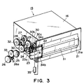
- a motor gear 26a integral with the output shaft of the motor 26, rotates.
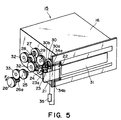
- the first coupling 43 in the image forming apparatus main assembly moves in the direction of an arrow mark D while rotating in the direction of an arrow mark C, without coupling with the first driving force transmission coupling 44, with which one of the longitudinal ends of the photosensitive drum 11 in the process cartridge 15 is provided. Therefore, the photosensitive drum 11 does not rotate in the direction reverse to the normal direction.
Landscapes
- Physics & Mathematics (AREA)
- General Physics & Mathematics (AREA)
- Engineering & Computer Science (AREA)
- Computer Vision & Pattern Recognition (AREA)
- Electrophotography Configuration And Component (AREA)
- Dry Development In Electrophotography (AREA)
Abstract
Description
Claims (31)
- A rotatable coupling member for transmitting driving forces to first driving means for driving a seal member for sealing an opening for discharging a developer from a developer accommodating container for accommodating the developer to unseal the opening and to second driving means for driving a stirring member for stirring the developer in the developer accommodating container,
wherein said drive transmission coupling member receives the driving force from a main assembly coupling member provided in a main assembly of an image forming apparatus to rotate in a first rotational direction to unseal the opening and to rotate in a second rotational direction which is opposite from the first rotational direction to drive said second driving means, said drive transmission coupling member comprising:a first portion for substantially aligning a rotational center of said drive transmission coupling member with a rotational center of the main assembly coupling member when said drive transmission coupling member rotates in the first rotational direction, anda second portion for permitting deviation between the rotational center of said drive transmission coupling member and the rotational center of the main assembly coupling member. - A drive transmission coupling member according to Claim 1, wherein a relative positional relation of the drive transmission coupling member relative to the main assembly coupling member is different between when it rotates in the first rotational direction and when it rotates in the second rotational direction.
- A drive transmission coupling member according to Claim 1, wherein said drive transmission coupling member is provided with a first driving force receiving portion for receiving the driving force from the main assembly coupling member and a second driving force receiving portion for receiving the driving force from the main assembly coupling member when it rotates in the second rotational direction.
- A drive transmission coupling member according to Claim 1, wherein a gap in a radial direction between said drive transmission coupling member and the main assembly coupling member is larger when it rotates in the second rotational direction than when it rotates in the first rotational direction.
- A drive transmission coupling member according to Claim 1, wherein said first portion is engaged with the main assembly coupling member.
- A drive transmission coupling member according to Claim 5, wherein the first portion includes a substantially semicircular portion.
- A drive transmission coupling member according to Claim 5, wherein said first portion includes a substantially triangular portion.
- A process cartridge detachably mountable to a main assembly of an image forming apparatus, comprising:an image bearing member;a developing device for developing an electrostatic image formed on a image bearing member with a developer, said developing device including a developer accommodating container, provided with an opening for discharging the developer, for discharging the developer, a seal member for sealing the opening, a stirring member for stirring the developer in the developer accommodating container, a first driving means for removing the seal member and a second driving means for driving the stirring member;a rotatable first drive transmission coupling member for receiving a driving force from a first main assembly coupling member provided in the main assembly of the apparatus to transmit the driving force to said image bearing member;a rotatable second drive transmission coupling member for receiving a driving force from a second main assembly coupling member provided in the main assembly of the apparatus to transmit the driving forces to said first and second driving means;
wherein one said second drive transmission coupling member transmits the driving force to said first driving means to unseal the opening, a rotational center of said second drive transmission coupling member and a rotational center of said second main assembly coupling member are substantially aligned, and the drive transmission between the first drive transmission coupling member and the first main assembly coupling member is disabled, and after the opening is unsealed, said second drive transmission coupling member transmits the driving force to said second driving means, and the rotational center of the second drive transmission coupling member and the rotational center of the second main assembly coupling member are permitted to deviate, and said first drive transmission coupling member receives driving force from said first main assembly coupling member. - A process cartridge according to Claim 8, wherein said second drive transmission coupling member transmit the driving force to said first driving means by rotating in a first rotational direction and transmits the driving force to said second driving means by rotating in a second rotational direction which is opposite from the first rotational direction, wherein said second drive transmission coupling member comprises a first portion for substantially aligning a rotational center of said second drive transmission coupling member with a rotational center of the second main assembly coupling member when it rotates in the first rotational direction and a second portion for permitting deviation between the rotational center of said second drive transmission coupling member and the rotational center of the second main assembly coupling member.
- A process cartridge according to Claim 9, wherein a relative positional relation of the second drive transmission coupling member relative to the second main assembly coupling member is different between when it rotates in the first rotational direction and when it rotates in the second rotational direction.
- A process cartridge according to Claim 9, wherein said second drive transmission coupling member is provided with a first driving force receiving portion for receiving the driving force from the second main assembly coupling member and a second driving force receiving portion for receiving the driving force from the second main assembly coupling member when it rotates in the second rotational direction.
- A process cartridge according to Claim 9, wherein a gap in a radial direction between said second drive transmission coupling member and the second main assembly coupling member is larger when it rotates in the second rotational direction when it rotates in the first rotational direction.
- A process cartridge according to Claim 9, wherein said first portion is engaged with the main assembly coupling member.
- A process cartridge according to Claim 13, wherein the first portion includes a substantially semicircular portion.
- A process cartridge according to Claim 13, wherein wherein said first portion includes a substantially triangular portion.
- An image forming apparatus to which a process cartridge is detachably mountable, said apparatus comprising:a process cartridge mounting member for mounting said process cartridge, which includes:an image bearing member;a developing device for developing an electrostatic image formed on a image bearing member with a developer, said developing device including a developer accommodating container, provided with an opening for discharging the developer, for discharging the developer, a seal member for sealing the opening, a stirring member for stirring the developer in the developer accommodating container, a first driving means for removing the seal member and a second driving means for driving the stirring member;a rotatable first drive transmission coupling member for receiving a driving force from a first main assembly coupling member provided in the main assembly of the apparatus to transmit the driving force to said image bearing member;a rotatable second drive transmission coupling member for receiving a driving force from a second main assembly coupling member provided in the main assembly of the apparatus to transmit the driving forces to said first and second driving means;said apparatus further comprising:a first main assembly coupling member for supplying a driving force to said first drive transmission coupling member;a second main assembly coupling member for supplying a driving force to said second drive transmission coupling member;
wherein one said second drive transmission coupling member transmits the driving force to said first driving means to unseal the opening, a rotational center of said second drive transmission coupling member and a rotational center of said second main assembly coupling member are substantially aligned, and the drive transmission between the first drive transmission coupling member and the first main assembly coupling member is disabled, and after the opening is unsealed, said second drive transmission coupling member transmits the driving force to said second driving means, and the rotational center of the second drive transmission coupling member and the rotational center of the second main assembly coupling member are permitted to deviate, and said first drive transmission coupling member receives driving force from said first main assembly coupling member. - An apparatus according to Claim 16, wherein said second drive transmission coupling member transmit the driving force to said first driving means by rotating in a first rotational direction and transmits the driving force to said second driving means by rotating in a second rotational direction which is opposite from the first rotational direction, wherein said second drive transmission coupling member comprises a first portion for substantially aligning a rotational center of said second drive transmission coupling member with a rotational center of the second main assembly coupling member when it rotates in the first rotational direction and a second portion for permitting deviation between the rotational center of said second drive transmission coupling member and the rotational center of the second main assembly coupling member.
- An apparatus according to Claim 17, wherein a relative positional relation of the second drive transmission coupling member relative to the second main assembly coupling member is different between when it rotates in the first rotational direction and when it rotates in the second rotational direction.
- An apparatus according to Claim 17, wherein said second drive transmission coupling member is provided with a first driving force receiving portion for receiving the driving force from the second main assembly coupling member and a second driving force receiving portion for receiving the driving force from the second main assembly coupling member when it rotates in the second rotational direction.
- An apparatus according to Claim 17, wherein a gap in a radial direction between said second drive transmission coupling member and the second main assembly coupling member is larger when it rotates in the second rotational direction when it rotates in the first rotational direction.
- An apparatus according to Claim 17, wherein said first portion is engaged with the main assembly coupling member.
- An apparatus according to Claim 21, wherein the first portion includes a substantially semicircular portion.
- An apparatus according to Claim 21, wherein said first portion includes a substantially triangular portion.
- A drive transmission coupling comprising:a male coupling member having first and second oppositely-facing radially-extending surfaces;a female coupling member having first and second oppositely-facing radially-extending surfaces;the respective first radially-extending surfaces of the male and female coupling members being cooperable when the male and female coupling members are in a first relative angular relationship for transmitting drive torque in a first rotary direction;the respective second radially-extending surfaces of the male and female coupling members being cooperable when the male and female coupling members in a second relative angular relationship for transmitting drive torque in a second rotary direction; and
wherein engagement means are operative between the first and second coupling members to prevent relative movement of the male and female coupling members in a radial direction when the first and second coupling members are in the said second relative angular relationship. - A drive coupling according to claim 24, wherein the male and female coupling members each have a pair of first radially-extending surfaces and a pair of second radially-extending surfaces.
- A drive coupling according to claim 24 or claim 25, wherein the engagement means comprises a circumferentially-extending projection and a cooperating recess formed on the respective second radially-extending surfaces of the male and female coupling members.
- A drive coupling according to claim 24 or claim 25, wherein the engagement means comprises cooperating respective external and internal circumferentially-extending surfaces of the male and female coupling members situated adjacent the radially outer ends of the respective second radially-extending surfaces.
- A male coupling member for a drive coupling according to any of claims 24 to 27.
- A female coupling member for a drive coupling according to any of claims 24 to 27.
- A process cartridge detachably mountable to a main assembly of an image forming apparatus and including a drive coupling member according to claim 28 or claim 29 for receiving a driving torque from said main assembly.
- A process cartridge detachably mountable to a main assembly of an image forming apparatus and including:a toner accommodating container having an opening for discharging the toner and a seal member for sealing the opening;a stirring member for stirring the toner in the toner accommodating container;a first drive coupling member for receiving a rotary drive in first and second driving directions from a cooperating second drive coupling member of said main assembly;first transmission means for transmitting driving force in a first rotary driving direction from the drive coupling member to a first driving means for removing the seal member from the opening;second transmission means for transmitting driving force in a second rotary driving direction from the drive coupling member to a second driving means for driving the stirring member; and
wherein the first drive coupling member includes engagement means cooperable with engagement means of the second drive coupling member to maintain the first and second drive coupling members in a coaxial relation when transmitting driving force in the first rotary driving direction.32. An electrophotographic image forming apparatus for detachably receiving a process cartridge according to claim 30 or claim 31, and including a drive coupling member for a drive coupling according to any of claims 24 to 27.
Applications Claiming Priority (2)
| Application Number | Priority Date | Filing Date | Title |
|---|---|---|---|
| JP16047299A JP3943761B2 (en) | 1999-06-08 | 1999-06-08 | Process cartridge and electrophotographic image forming apparatus |
| JP16047299 | 1999-06-08 |
Publications (3)
| Publication Number | Publication Date |
|---|---|
| EP1059571A2 true EP1059571A2 (en) | 2000-12-13 |
| EP1059571A3 EP1059571A3 (en) | 2002-01-16 |
| EP1059571B1 EP1059571B1 (en) | 2005-06-01 |
Family
ID=15715703
Family Applications (1)
| Application Number | Title | Priority Date | Filing Date |
|---|---|---|---|
| EP00304813A Expired - Lifetime EP1059571B1 (en) | 1999-06-08 | 2000-06-07 | Coupling member, process cartridge and image forming apparatus |
Country Status (6)
| Country | Link |
|---|---|
| US (1) | US6301457B1 (en) |
| EP (1) | EP1059571B1 (en) |
| JP (1) | JP3943761B2 (en) |
| KR (1) | KR100368094B1 (en) |
| CN (1) | CN1139012C (en) |
| DE (1) | DE60020452T2 (en) |
Cited By (4)
| Publication number | Priority date | Publication date | Assignee | Title |
|---|---|---|---|---|
| EP1253485A2 (en) | 2001-04-27 | 2002-10-30 | Canon Kabushiki Kaisha | Process cartridge, electrophotographic image forming apparatus and fixing method of electrical contact part |
| EP1168100A3 (en) * | 2000-06-26 | 2009-02-04 | Canon Kabushiki Kaisha | Toner seal member, development cartridge, process cartridge and electrophotographic image forming apparatus |
| EP2202588A1 (en) * | 2008-12-23 | 2010-06-30 | Sagem Communications Sas | Printing unit |
| EP2711782A3 (en) * | 2012-09-25 | 2017-03-15 | Kyocera Document Solutions Inc. | Image forming apparatus, toner case and drive transmission mechanism |
Families Citing this family (34)
| Publication number | Priority date | Publication date | Assignee | Title |
|---|---|---|---|---|
| JP3442047B2 (en) * | 2000-11-17 | 2003-09-02 | キヤノン株式会社 | Process cartridge and electrophotographic image forming apparatus |
| JP2002214896A (en) | 2001-01-19 | 2002-07-31 | Canon Inc | Developer container, process cartridge, and electrophotographic image forming apparatus |
| JP3564080B2 (en) | 2001-04-27 | 2004-09-08 | キヤノン株式会社 | Process cartridge remanufacturing method |
| JP3542569B2 (en) | 2001-04-27 | 2004-07-14 | キヤノン株式会社 | Process cartridge remanufacturing method |
| JP2003255806A (en) * | 2002-02-28 | 2003-09-10 | Canon Inc | Process cartridge, developing device and image forming device |
| JP3677506B2 (en) * | 2002-08-07 | 2005-08-03 | 株式会社リコー | Belt drive control method and apparatus, belt apparatus, image forming apparatus, process cartridge, program, and recording medium |
| JP3919779B2 (en) | 2003-08-29 | 2007-05-30 | キヤノン株式会社 | Electrophotographic image forming apparatus |
| JP3997213B2 (en) * | 2004-03-31 | 2007-10-24 | キヤノン株式会社 | Electrophotographic image forming apparatus |
| JP3984978B2 (en) * | 2004-07-06 | 2007-10-03 | キヤノン株式会社 | Process cartridge and electrophotographic image forming apparatus |
| US20060008289A1 (en) * | 2004-07-06 | 2006-01-12 | Canon Kabushiki Kaisha | Electrophotographic image forming apparatus and process cartridge |
| JP3970279B2 (en) * | 2004-07-30 | 2007-09-05 | キヤノン株式会社 | Process cartridge and electrophotographic image forming apparatus |
| JP4695913B2 (en) * | 2005-04-12 | 2011-06-08 | キヤノン株式会社 | Electrophotographic image forming apparatus |
| KR100729618B1 (en) | 2005-10-04 | 2007-06-19 | 삼성전자주식회사 | Drive device, process cartridge and image forming device having same |
| JP4946157B2 (en) * | 2006-05-02 | 2012-06-06 | 富士ゼロックス株式会社 | Image forming unit |
| JP4364214B2 (en) * | 2006-05-13 | 2009-11-11 | 村田機械株式会社 | Drive transmission mechanism and image forming apparatus using the same |
| JP4464435B2 (en) | 2006-12-11 | 2010-05-19 | キヤノン株式会社 | Process cartridge and electrophotographic image forming apparatus |
| JP4665927B2 (en) * | 2007-03-27 | 2011-04-06 | ブラザー工業株式会社 | Cartridge and image forming apparatus |
| KR100781364B1 (en) * | 2007-05-02 | 2007-11-30 | 삼성전자주식회사 | Drive device, process cartridge and image forming device having same |
| JP5219626B2 (en) * | 2008-05-27 | 2013-06-26 | キヤノン株式会社 | Process cartridge and image forming apparatus |
| JP4869289B2 (en) * | 2008-05-27 | 2012-02-08 | キヤノン株式会社 | Process cartridge and electrophotographic image forming apparatus |
| JP5344538B2 (en) * | 2008-05-27 | 2013-11-20 | キヤノン株式会社 | Process cartridge assembling method, process cartridge disassembling method, process cartridge remanufacturing method, and process cartridge |
| JP5517732B2 (en) | 2010-05-11 | 2014-06-11 | キヤノン株式会社 | Process cartridge and image forming apparatus |
| JP5517989B2 (en) | 2010-05-14 | 2014-06-11 | キヤノン株式会社 | Process cartridge and image forming apparatus |
| JP5943685B2 (en) | 2012-04-13 | 2016-07-05 | キヤノン株式会社 | Developing unit, process cartridge, and electrophotographic image forming apparatus |
| JP6723694B2 (en) | 2015-07-01 | 2020-07-15 | キヤノン株式会社 | Image forming apparatus and cartridge |
| JP6665635B2 (en) * | 2016-03-31 | 2020-03-13 | ブラザー工業株式会社 | Developing cartridge |
| CN107305338B (en) * | 2016-04-19 | 2024-01-16 | 纳思达股份有限公司 | Process cartridge and process cartridge assembling method |
| EP3455678A1 (en) * | 2016-05-10 | 2019-03-20 | Clover Technologies Group, LLC | Remanufactured toner cartridge and test method therefor |
| BR112018074598B1 (en) * | 2016-06-14 | 2024-01-16 | Canon Kabushiki Kaisha | PROCESS CARTRIDGE AND ELECTROPHOTOGRAPHIC IMAGE FORMING APPARATUS |
| TWI638247B (en) * | 2017-08-15 | 2018-10-11 | 上福全球科技股份有限公司 | Toner cartridge |
| CN108957997B (en) * | 2018-07-27 | 2024-04-05 | 珠海天威飞马打印耗材有限公司 | Process cartridge |
| JP7047695B2 (en) | 2018-09-28 | 2022-04-05 | ブラザー工業株式会社 | Develop cartridge |
| JP7449215B2 (en) * | 2019-10-11 | 2024-03-13 | キヤノントッキ株式会社 | Alignment equipment, alignment method, film forming equipment and film forming method |
| KR20220033679A (en) | 2020-09-10 | 2022-03-17 | 휴렛-팩커드 디벨롭먼트 컴퍼니, 엘.피. | Connection structure for coupling with toner cartridge |
Family Cites Families (11)
| Publication number | Priority date | Publication date | Assignee | Title |
|---|---|---|---|---|
| GB768997A (en) * | 1953-07-09 | 1957-02-27 | Frank R Ford Ltd | Improvements relating to rotary motion transmission couplings for duplicating machines |
| JPS6449864U (en) * | 1987-09-17 | 1989-03-28 | ||
| JP2533350B2 (en) * | 1988-01-29 | 1996-09-11 | キヤノン株式会社 | Process cartridge and image forming apparatus |
| JPH096214A (en) * | 1995-06-19 | 1997-01-10 | Canon Inc | Process cartridge, supply cartridge and image forming apparatus |
| JP3507932B2 (en) * | 1995-09-26 | 2004-03-15 | 株式会社リコー | Toner container |
| JPH09114352A (en) * | 1995-10-16 | 1997-05-02 | Canon Inc | Process cartridge and image forming apparatus |
| JP3745049B2 (en) * | 1996-09-26 | 2006-02-15 | キヤノン株式会社 | Process cartridge and electrophotographic image forming apparatus |
| JPH10222041A (en) | 1996-12-03 | 1998-08-21 | Canon Inc | Process cartridge and electrophotographic image forming apparatus |
| JP3363727B2 (en) | 1996-12-12 | 2003-01-08 | キヤノン株式会社 | Process cartridge, electrophotographic image forming apparatus, process cartridge assembling method, and waste toner container assembling method |
| JPH11119535A (en) * | 1997-10-20 | 1999-04-30 | Fuji Xerox Co Ltd | Detachable developer storage case and developing device |
| JP3083091B2 (en) * | 1997-12-09 | 2000-09-04 | キヤノン株式会社 | Seal member for developer storage container, developer storage container, developing device, process cartridge, and image forming apparatus |
-
1999
- 1999-06-08 JP JP16047299A patent/JP3943761B2/en not_active Expired - Fee Related
-
2000
- 2000-06-06 US US09/587,912 patent/US6301457B1/en not_active Expired - Lifetime
- 2000-06-07 KR KR10-2000-0030943A patent/KR100368094B1/en not_active Expired - Fee Related
- 2000-06-07 EP EP00304813A patent/EP1059571B1/en not_active Expired - Lifetime
- 2000-06-07 DE DE60020452T patent/DE60020452T2/en not_active Expired - Lifetime
- 2000-06-08 CN CNB001181254A patent/CN1139012C/en not_active Expired - Fee Related
Cited By (6)
| Publication number | Priority date | Publication date | Assignee | Title |
|---|---|---|---|---|
| EP1168100A3 (en) * | 2000-06-26 | 2009-02-04 | Canon Kabushiki Kaisha | Toner seal member, development cartridge, process cartridge and electrophotographic image forming apparatus |
| EP1253485A2 (en) | 2001-04-27 | 2002-10-30 | Canon Kabushiki Kaisha | Process cartridge, electrophotographic image forming apparatus and fixing method of electrical contact part |
| EP1253485A3 (en) * | 2001-04-27 | 2007-05-30 | Canon Kabushiki Kaisha | Process cartridge, electrophotographic image forming apparatus and fixing method of electrical contact part |
| EP2388661A1 (en) * | 2001-04-27 | 2011-11-23 | Canon Kabushiki Kaisha | Process cartridg and fixing method of electrical contact part |
| EP2202588A1 (en) * | 2008-12-23 | 2010-06-30 | Sagem Communications Sas | Printing unit |
| EP2711782A3 (en) * | 2012-09-25 | 2017-03-15 | Kyocera Document Solutions Inc. | Image forming apparatus, toner case and drive transmission mechanism |
Also Published As
| Publication number | Publication date |
|---|---|
| KR100368094B1 (en) | 2003-01-15 |
| CN1276543A (en) | 2000-12-13 |
| EP1059571A3 (en) | 2002-01-16 |
| JP2000347487A (en) | 2000-12-15 |
| DE60020452T2 (en) | 2006-05-04 |
| EP1059571B1 (en) | 2005-06-01 |
| KR20010020956A (en) | 2001-03-15 |
| CN1139012C (en) | 2004-02-18 |
| US6301457B1 (en) | 2001-10-09 |
| JP3943761B2 (en) | 2007-07-11 |
| DE60020452D1 (en) | 2005-07-07 |
Similar Documents
| Publication | Publication Date | Title |
|---|---|---|
| EP1059571B1 (en) | Coupling member, process cartridge and image forming apparatus | |
| US9523942B2 (en) | Developer accommodating container, developing cartridge, process cartridge and image forming apparatus | |
| US9069289B2 (en) | Developer container, developing cartridge, process cartridge and image forming apparatus | |
| US9229371B2 (en) | Developer container, developing cartridge, process cartridge and image forming apparatus | |
| US9188906B2 (en) | Cartridge, developing cartridge, process cartridge and image forming apparatus | |
| JP3950568B2 (en) | Developer container, developing device, process cartridge, and image forming apparatus | |
| EP0871092B1 (en) | Toner frame, process cartridge and image forming apparatus | |
| US9291942B2 (en) | Developer accommodating unit, process cartridge and image forming apparatus | |
| US7231164B2 (en) | Developing unit, developing cartridge, and image forming apparatus | |
| US20070110478A1 (en) | Electrophotographic photosensitive drum, process cartridge, and electrophotographic image forming apparatus | |
| EP1107073B1 (en) | Image forming apparatus with controlled drive source for removal of a sealing member in a developing cartridge | |
| JPH10105026A (en) | Process cartridge and electrophotographic image forming apparatus | |
| JP3507372B2 (en) | Developing device, process cartridge, and electrophotographic image forming device | |
| KR100608058B1 (en) | Developer driving device and image forming device using the same | |
| JP3814524B2 (en) | Powder container, developing device including the same, and electrophotographic image forming apparatus | |
| JP4035552B2 (en) | Developer container, developing device, process cartridge, and image forming apparatus | |
| JP3984984B2 (en) | Developing device, process cartridge, and electrophotographic image forming apparatus | |
| JPH09288425A (en) | Toner seal automatic opening device, process cartridge, and electrophotographic image forming apparatus | |
| JP4677113B2 (en) | Electrophotographic image forming apparatus | |
| JP3450568B2 (en) | Automatic toner seal opening device, process cartridge, and electrophotographic image forming device | |
| JPH11258964A (en) | Electrophotographic image forming apparatus | |
| JP2001305839A (en) | Toner seal winding member, developer storage container, developing cartridge, process cartridge, electrophotographic image forming apparatus, and method of assembling toner seal member and toner seal winding member | |
| JP2021099407A (en) | Drive transmission structure, developer container, and image forming apparatus | |
| JP2002268347A (en) | Developing cartridge, process cartridge, and electrophotographic image forming apparatus | |
| JPH11249497A (en) | Process cartridge |
Legal Events
| Date | Code | Title | Description |
|---|---|---|---|
| PUAI | Public reference made under article 153(3) epc to a published international application that has entered the european phase |
Free format text: ORIGINAL CODE: 0009012 |
|
| AK | Designated contracting states |
Kind code of ref document: A2 Designated state(s): CH DE FR GB IT LI Kind code of ref document: A2 Designated state(s): AT BE CH CY DE DK ES FI FR GB GR IE IT LI LU MC NL PT SE |
|
| AX | Request for extension of the european patent |
Free format text: AL;LT;LV;MK;RO;SI |
|
| PUAL | Search report despatched |
Free format text: ORIGINAL CODE: 0009013 |
|
| AK | Designated contracting states |
Kind code of ref document: A3 Designated state(s): AT BE CH CY DE DK ES FI FR GB GR IE IT LI LU MC NL PT SE |
|
| AX | Request for extension of the european patent |
Free format text: AL;LT;LV;MK;RO;SI |
|
| 17P | Request for examination filed |
Effective date: 20020628 |
|
| AKX | Designation fees paid |
Free format text: CH DE FR GB IT LI |
|
| 17Q | First examination report despatched |
Effective date: 20040407 |
|
| GRAP | Despatch of communication of intention to grant a patent |
Free format text: ORIGINAL CODE: EPIDOSNIGR1 |
|
| RIC1 | Information provided on ipc code assigned before grant |
Ipc: 7G 03G 15/08 A Ipc: 7F 16D 3/00 B |
|
| RIN1 | Information on inventor provided before grant (corrected) |
Inventor name: ASANO, NAOKI Inventor name: CHADANI, KAZUO |
|
| GRAS | Grant fee paid |
Free format text: ORIGINAL CODE: EPIDOSNIGR3 |
|
| GRAA | (expected) grant |
Free format text: ORIGINAL CODE: 0009210 |
|
| AK | Designated contracting states |
Kind code of ref document: B1 Designated state(s): CH DE FR GB IT LI |
|
| PG25 | Lapsed in a contracting state [announced via postgrant information from national office to epo] |
Ref country code: IT Free format text: LAPSE BECAUSE OF FAILURE TO SUBMIT A TRANSLATION OF THE DESCRIPTION OR TO PAY THE FEE WITHIN THE PRESCRIBED TIME-LIMIT;WARNING: LAPSES OF ITALIAN PATENTS WITH EFFECTIVE DATE BEFORE 2007 MAY HAVE OCCURRED AT ANY TIME BEFORE 2007. THE CORRECT EFFECTIVE DATE MAY BE DIFFERENT FROM THE ONE RECORDED. Effective date: 20050601 Ref country code: LI Free format text: LAPSE BECAUSE OF FAILURE TO SUBMIT A TRANSLATION OF THE DESCRIPTION OR TO PAY THE FEE WITHIN THE PRESCRIBED TIME-LIMIT Effective date: 20050601 Ref country code: CH Free format text: LAPSE BECAUSE OF FAILURE TO SUBMIT A TRANSLATION OF THE DESCRIPTION OR TO PAY THE FEE WITHIN THE PRESCRIBED TIME-LIMIT Effective date: 20050601 |
|
| REG | Reference to a national code |
Ref country code: GB Ref legal event code: FG4D |
|
| REG | Reference to a national code |
Ref country code: CH Ref legal event code: EP |
|
| REG | Reference to a national code |
Ref country code: IE Ref legal event code: FG4D |
|
| REF | Corresponds to: |
Ref document number: 60020452 Country of ref document: DE Date of ref document: 20050707 Kind code of ref document: P |
|
| REG | Reference to a national code |
Ref country code: CH Ref legal event code: PL |
|
| ET | Fr: translation filed | ||
| PLBE | No opposition filed within time limit |
Free format text: ORIGINAL CODE: 0009261 |
|
| STAA | Information on the status of an ep patent application or granted ep patent |
Free format text: STATUS: NO OPPOSITION FILED WITHIN TIME LIMIT |
|
| 26N | No opposition filed |
Effective date: 20060302 |
|
| PGFP | Annual fee paid to national office [announced via postgrant information from national office to epo] |
Ref country code: FR Payment date: 20130718 Year of fee payment: 14 |
|
| REG | Reference to a national code |
Ref country code: FR Ref legal event code: ST Effective date: 20150227 |
|
| PG25 | Lapsed in a contracting state [announced via postgrant information from national office to epo] |
Ref country code: FR Free format text: LAPSE BECAUSE OF NON-PAYMENT OF DUE FEES Effective date: 20140630 |
|
| PGFP | Annual fee paid to national office [announced via postgrant information from national office to epo] |
Ref country code: GB Payment date: 20150626 Year of fee payment: 16 Ref country code: DE Payment date: 20150630 Year of fee payment: 16 |
|
| REG | Reference to a national code |
Ref country code: DE Ref legal event code: R119 Ref document number: 60020452 Country of ref document: DE |
|
| GBPC | Gb: european patent ceased through non-payment of renewal fee |
Effective date: 20160607 |
|
| PG25 | Lapsed in a contracting state [announced via postgrant information from national office to epo] |
Ref country code: DE Free format text: LAPSE BECAUSE OF NON-PAYMENT OF DUE FEES Effective date: 20170103 |
|
| PG25 | Lapsed in a contracting state [announced via postgrant information from national office to epo] |
Ref country code: GB Free format text: LAPSE BECAUSE OF NON-PAYMENT OF DUE FEES Effective date: 20160607 |