CN1139012C - Connector, processing box and imaging apparatus - Google Patents
Connector, processing box and imaging apparatus Download PDFInfo
- Publication number
- CN1139012C CN1139012C CNB001181254A CN00118125A CN1139012C CN 1139012 C CN1139012 C CN 1139012C CN B001181254 A CNB001181254 A CN B001181254A CN 00118125 A CN00118125 A CN 00118125A CN 1139012 C CN1139012 C CN 1139012C
- Authority
- CN
- China
- Prior art keywords
- connector
- drive transmitting
- master component
- driving force
- drive
- Prior art date
- Legal status (The legal status is an assumption and is not a legal conclusion. Google has not performed a legal analysis and makes no representation as to the accuracy of the status listed.)
- Expired - Fee Related
Links
Images


Classifications
-
- G—PHYSICS
- G03—PHOTOGRAPHY; CINEMATOGRAPHY; ANALOGOUS TECHNIQUES USING WAVES OTHER THAN OPTICAL WAVES; ELECTROGRAPHY; HOLOGRAPHY
- G03G—ELECTROGRAPHY; ELECTROPHOTOGRAPHY; MAGNETOGRAPHY
- G03G21/00—Arrangements not provided for by groups G03G13/00 - G03G19/00, e.g. cleaning, elimination of residual charge
- G03G21/16—Mechanical means for facilitating the maintenance of the apparatus, e.g. modular arrangements
- G03G21/18—Mechanical means for facilitating the maintenance of the apparatus, e.g. modular arrangements using a processing cartridge, whereby the process cartridge comprises at least two image processing means in a single unit
- G03G21/1839—Means for handling the process cartridge in the apparatus body
- G03G21/1857—Means for handling the process cartridge in the apparatus body for transmitting mechanical drive power to the process cartridge, drive mechanisms, gears, couplings, braking mechanisms
- G03G21/186—Axial couplings
-
- G—PHYSICS
- G03—PHOTOGRAPHY; CINEMATOGRAPHY; ANALOGOUS TECHNIQUES USING WAVES OTHER THAN OPTICAL WAVES; ELECTROGRAPHY; HOLOGRAPHY
- G03G—ELECTROGRAPHY; ELECTROPHOTOGRAPHY; MAGNETOGRAPHY
- G03G15/00—Apparatus for electrographic processes using a charge pattern
-
- G—PHYSICS
- G03—PHOTOGRAPHY; CINEMATOGRAPHY; ANALOGOUS TECHNIQUES USING WAVES OTHER THAN OPTICAL WAVES; ELECTROGRAPHY; HOLOGRAPHY
- G03G—ELECTROGRAPHY; ELECTROPHOTOGRAPHY; MAGNETOGRAPHY
- G03G15/00—Apparatus for electrographic processes using a charge pattern
- G03G15/06—Apparatus for electrographic processes using a charge pattern for developing
- G03G15/08—Apparatus for electrographic processes using a charge pattern for developing using a solid developer, e.g. powder developer
- G03G15/0822—Arrangements for preparing, mixing, supplying or dispensing developer
- G03G15/0877—Arrangements for metering and dispensing developer from a developer cartridge into the development unit
- G03G15/0881—Sealing of developer cartridges
- G03G15/0882—Sealing of developer cartridges by a peelable sealing film
-
- G—PHYSICS
- G03—PHOTOGRAPHY; CINEMATOGRAPHY; ANALOGOUS TECHNIQUES USING WAVES OTHER THAN OPTICAL WAVES; ELECTROGRAPHY; HOLOGRAPHY
- G03G—ELECTROGRAPHY; ELECTROPHOTOGRAPHY; MAGNETOGRAPHY
- G03G21/00—Arrangements not provided for by groups G03G13/00 - G03G19/00, e.g. cleaning, elimination of residual charge
- G03G21/16—Mechanical means for facilitating the maintenance of the apparatus, e.g. modular arrangements
- G03G21/18—Mechanical means for facilitating the maintenance of the apparatus, e.g. modular arrangements using a processing cartridge, whereby the process cartridge comprises at least two image processing means in a single unit
- G03G21/1839—Means for handling the process cartridge in the apparatus body
- G03G21/1857—Means for handling the process cartridge in the apparatus body for transmitting mechanical drive power to the process cartridge, drive mechanisms, gears, couplings, braking mechanisms
- G03G21/1864—Means for handling the process cartridge in the apparatus body for transmitting mechanical drive power to the process cartridge, drive mechanisms, gears, couplings, braking mechanisms associated with a positioning function
-
- G—PHYSICS
- G03—PHOTOGRAPHY; CINEMATOGRAPHY; ANALOGOUS TECHNIQUES USING WAVES OTHER THAN OPTICAL WAVES; ELECTROGRAPHY; HOLOGRAPHY
- G03G—ELECTROGRAPHY; ELECTROPHOTOGRAPHY; MAGNETOGRAPHY
- G03G2215/00—Apparatus for electrophotographic processes
- G03G2215/08—Details of powder developing device not concerning the development directly
- G03G2215/0875—Arrangements for shipping or transporting of the developing device to or from the user
- G03G2215/0877—Sealing of the developing device opening, facing the image-carrying member
- G03G2215/088—Peelable sealing film
-
- G—PHYSICS
- G03—PHOTOGRAPHY; CINEMATOGRAPHY; ANALOGOUS TECHNIQUES USING WAVES OTHER THAN OPTICAL WAVES; ELECTROGRAPHY; HOLOGRAPHY
- G03G—ELECTROGRAPHY; ELECTROPHOTOGRAPHY; MAGNETOGRAPHY
- G03G2221/00—Processes not provided for by group G03G2215/00, e.g. cleaning or residual charge elimination
- G03G2221/16—Mechanical means for facilitating the maintenance of the apparatus, e.g. modular arrangements and complete machine concepts
- G03G2221/18—Cartridge systems
- G03G2221/183—Process cartridge
Landscapes
- Physics & Mathematics (AREA)
- General Physics & Mathematics (AREA)
- Engineering & Computer Science (AREA)
- Computer Vision & Pattern Recognition (AREA)
- Electrophotography Configuration And Component (AREA)
- Dry Development In Electrophotography (AREA)
Abstract
A rotatable coupling member for transmitting driving forces to first driving means and to second driving means, wherein the drive transmission coupling member receives the driving force from a main assembly coupling member provided in a main assembly of an image, the drive transmission coupling member including a first portion for substantially aligning a rotational center of the drive transmission coupling member with a rotational center of the main assembly coupling member when the drive transmission coupling member rotates in the first rotational direction, and a second portion for permitting deviation between the rotational center of the drive transmission coupling member and the rotational center of the main assembly coupling member.
Description
Technical field
The present invention relates to can be used for a kind of connector and a kind of handle box of image device.It also relates to a kind of image device.
Background technology
In this instructions, term " image device " is meant a kind of a kind of given image formation method that is used on recording medium, uses, and electrofax image formation method preferably forms the equipment of image.As a kind of like this example of image device, electrophotographic copier, electrophotographic printer (laser beam printer, LED printer etc.), facsimile equipment, word processor etc. are arranged.
Term " handle box " is meant the box in the master component that removably can be installed in image device, and at least one of charging device of integral arrangement, a developing apparatus and a scavenge unit wherein; And image bearing member.
Routinely, adopt the image device of electrofax imaging procedures also to adopt a process cartridge system, resemble an electrophotography photosensitiving piece of part and to act on one or more treating apparatus on the electrophotography photosensitiving piece as carrying in view of the above, integrated one-tenth removably is installed in the box in the master component of image device.Also according to this process cartridge system, image device can be safeguarded separately by the user, and do not rely on the attendant, significantly improves operating efficiency.Therefore, process cartridge system extensively is used in the image device field.
Comprise one or more treating apparatus such as above-mentioned handle box a kind of.One of these treating apparatus are developing apparatuss, and this developing apparatus integral body comprises a developer storing container (toner container) and a developing apparatus that is used for supporting a development part of wherein storing toner.Till handle box was come into operation for the first time, the passage between toner container and developing apparatus kept sealing by a seal (toner sealing).When handle box is come into operation for the first time, tear the sealing part.
As everyone knows, some handle boxes or electrophotographic image-forming (hereinafter for " image device ") are equipped with a driving force transfer device that is used for receiving from the master component of image device driving force, tear it with automatic winding seal.
The seal of conventional image device twines driving force transfer device, handle box or toner container so to be built, thereby when the winding of seal finished, it must stop transmission of drive force, and perhaps it is closed.Therefore, equipment master component, handle box or toner container must be equipped with a driving force transfer device that is exclusively used in the winding of seal.And, in multiple image device master component, drive a toner sealing simultaneously and twine unit and a toner agitating unit.
A kind of like this layout makes the drive unit complexity of equipment master component side.And agitating unit and toner sealing drive the increase that causes power consumption when twining the unit.
Summary of the invention
The present invention is one of result who further develops of above-mentioned routine techniques.
As a kind of means that address the above problem, can imagine: the driving force transmitting portions is divided into two parts, that is, one is used for that driving force is delivered to part on photosensitive drums and the toner stirring parts and one and is used for driving force is delivered to the part that seal twines the unit; With begin to drive photosensitive drums and toner stirring parts after twining the unit finish driving the toner sealing.Except that the problems referred to above, conventional structure is subjected to the evil of another problem.In other words, when seal began to twine, handle box was also located reliably with respect to the equipment master component, and therefore, when the seal winding was torn, the handle box driving force of origin selfimaging equipment master component sometimes caused vibration.
Because handle box vibration, so in cartridge side, through the bulging connector of the drive force electronic photographic sensitive of its origin selfimaging equipment master component, can not aim at the connector of image device master component side, make the connector of box side be difficult to be inserted in the connector of master component side.
Fundamental purpose of the present invention is, provide a kind of driving force to transmit connector, a kind of handle box, reach a kind of image device, connector is delivered to a drive unit to driving force so that when tearing seal when driving force is transmitted for this, makes that might be fixed on the position that driving force transmits between the connector of connector and master component side approx concerns.
Another object of the present invention is to provide a kind of driving force to transmit connector, a kind of handle box, reaches a kind of image device, when this is delivered to a stirring parts to driving force when driving force transmission connector, make that might in fact shake the fixing in the past position between the connector of driving force transmission connector and master component side concerns.
Another object of the present invention is to provide: a kind of connector, be used for driving one and when tearing seal, can not cause the handle box vibration and tear and allow the connector of image device master component side to be easy to and the drive unit that carries the connector engagement that resembles part after finishing at seal, and drive unit that is used for stirring parts of driving; A kind of handle box comprises a kind of like this connector; And a kind of image device, wherein a kind of like this handle box is dismountable installable.
According to first aspect present invention, provide a kind of pivotable drive to transmit connector, be used for driving force is delivered to: first drive unit, be used to drive a seal that is used for sealing an opening opening this opening, this opening is used for developer is discharged from being used for the developer-accommodating vessel of receiving photographic developer; With second drive unit, be used for driving a stirring parts, so that the developer in the stirring developer-accommodating vessel, the master component connector of wherein said drive transmitting connector from be provided at the image device master component receives driving force, to drive described first drive unit and open on first rotation direction of opening and rotate at one, and one and first direction of rotation, to rotate on second rotation direction that drives described second drive unit, described drive transmitting connector comprises: a first, when described drive transmitting connector receives from the driving force of master component connector when rotating on first rotation direction, be used for basically the center of rotation of described drive transmitting connector being aimed at the center of rotation of master component connector, and second portion, when described drive transmitting connector receives from the driving force of master component connector when rotating, be used for allowing departing between the center of rotation of the center of rotation of described drive transmitting connector and master component connector on second rotation direction.
According to second aspect present invention, the handle box on a kind of master component that removably is installed to an image device is provided, comprising: one carries and resembles part; A developing apparatus, being used for developing by means of developer is formed on the electrostatic image that resembled on the part in described year, and described developing apparatus comprises that a developer-accommodating vessel that an opening that is used for discharging developer is housed, seal that is used for sealing this opening, one are used for stirring the stirring parts of the developer in the developer-accommodating vessel, first drive unit and second drive unit that is used for driving stirring parts that is used for removing seal; Rotatable first a drive transmitting connector, the first master component connector that is used for from the master component that is provided at image device receives driving force, resembles part in described year so that driving force is delivered to; Rotatable second a drive transmitting connector, the second master component connector that is used for from the master component that is provided at image device receives driving force, driving force is delivered to described first and second drive units; Wherein work as the described second drive transmitting connector driving force is delivered to described first drive unit, when opening opening, the center of rotation substantial registration of the center of rotation of the described second drive transmitting connector and the described second master component connector, and forbid the drive transmitting between the first drive transmitting connector and the first master component connector, and after opening opening, the described second drive transmitting connector is delivered to described second drive unit to driving force, and allow the center of rotation of the second drive transmitting connector and the center of rotation of the second master component connector to depart from, and the described first drive transmitting connector receive driving force from the described first master component connector.
According to third aspect present invention, provide a kind of handle box removably to be installed to image device on it, described image device comprises: a handle box fabricated section, be used for installing described handle box, this handle box comprises: one carries and resembles part; A developing apparatus, being used for developing by means of developer is formed on the electrostatic image that resembled on the part in described year, and described developing apparatus comprises that a developer-accommodating vessel that an opening that is used for discharging developer is housed, seal that is used for sealing this opening, one are used for stirring the stirring parts of the developer in the developer-accommodating vessel, first drive unit and second drive unit that is used for driving stirring parts that is used for removing seal; Rotatable first a drive transmitting connector, the first master component connector that is used for from be provided at the image device master component receives driving force, resembles part in described year so that driving force is delivered to; Rotatable second a drive transmitting connector, the second master component connector that is used for from be provided at equipment imaging master component receives driving force, driving force is delivered to described first and second drive units; Described image device further comprises: the described first master component connector is used for driving force is supplied to the described first drive transmitting connector; The described second master component connector is used for driving force is supplied to the described second drive transmitting connector; Wherein, when the described second drive transmitting connector is delivered to described first drive unit to driving force, when opening opening, the center of rotation substantial registration of the center of rotation of the described second drive transmitting connector and the described second master component connector, and forbid the drive transmitting between the first drive transmitting connector and the first master component connector, and after opening opening, the described second drive transmitting connector is delivered to described second drive unit to driving force, and allow the center of rotation of the second drive transmitting connector and the center of rotation of the second master component connector to depart from, and the described first drive transmitting connector receive driving force from the described first master component connector.
Description of drawings
Connection with figures is considered the following description of most preferred embodiment of the present invention, these and other purposes of the present invention, feature, and advantage will become clearer.
Fig. 1 is that the essential part of the handle box in the most preferred embodiment of the present invention is perpendicular to the box schematic sectional view at plane place longitudinally.
Fig. 2 is that the essential part of the image device in most preferred embodiment of the present invention is perpendicular to the handle box schematic sectional view at plane place longitudinally.
Fig. 3 is the schematic sectional view of toner storage container that is in the handle box of brand-new state in the present invention's first most preferred embodiment.
Fig. 4 is the schematic sectional view of the toner storage container of the handle box in the first embodiment of the invention, has got around the toner sealing from this handle box.
Fig. 5 is the schematic sectional view of the toner storage container of the handle box among first embodiment, and wherein the toner stirring parts has begun to rotate.
Fig. 6 is the schematic isometric of the handle box among first embodiment, is twining the toner sealing this moment.
Fig. 7 is the schematic isometric of the handle box among first embodiment, and this moment, photosensitive drums and stirring parts were rotated.
Fig. 8 is first connection of the handle box among first embodiment and first schematic isometric that connects of image device master component.
Fig. 9 be among first embodiment handle box second connect and the image device master component second connect be combined in cut-open view perpendicular to the place, plane of two connector axis, two connectors were torn on the direction of toner sealing and were rotated this moment.
Figure 10 be among first embodiment handle box second connect and the image device master component second connect be combined in cut-open view perpendicular to the place, plane of two connector axis, this moment, two connectors just rotated on the direction of stirring parts.
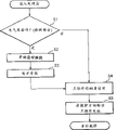
Figure 11 is the process flow diagram that is used for first embodiment.
Figure 12 is the mnemocircuit figure that is used for first embodiment.
Figure 13 be among second embodiment handle box second connect and the image device master component second connect be combined in cut-open view perpendicular to the place, plane of two connector axis, two connectors were torn on the direction of toner sealing and were rotated this moment.
Figure 14 be among second embodiment handle box second connect and the image device master component second connect be combined in cut-open view perpendicular to the place, plane of two connector axis, this moment, two connectors just rotated on the direction of stirring parts.
Figure 15 be among the 3rd embodiment handle box second connect and the image device master component second connect be combined in cut-open view perpendicular to the place, plane of two connector axis, two connectors were torn on the direction of toner sealing and were rotated this moment.
Figure 16 be among the 3rd embodiment handle box second connect and the image device master component second connect be combined in cut-open view perpendicular to the place, plane of two connector axis, this moment, two connectors just rotated on the direction of stirring parts.
Embodiment
(embodiment 1)
Hereinafter, with reference to Fig. 1 and 2 most preferred embodiment of the present invention will be described.
(description of handle box and image device master component)
Fig. 1 shows according to the essential part of handle box of the present invention perpendicular to the box xsect at place, plane longitudinally.Fig. 2 shows according to the essential part of image device of the present invention perpendicular to the handle box xsect at place, plane longitudinally.This handle box is equipped with one and carries and to resemble part and one or more acting on carried the treating apparatus that resembles on the part.With regard to treating apparatus, for example, there are the charging device that carries the peripheral surface that resembles part of being used for charging, one to be used for toner image is formed on and carry the developing apparatus that resembles on the part, and scavenge unit that is used for removing the toner on the peripheral surface that remains in image device.Handle box is equipped with an electrophotography photosensitiving piece as carrying at least one treating apparatus that resembles in part and the treating apparatus listed above.
With reference to Fig. 1, under the situation of handle box 15 in this embodiment, charging roller 12 as charging device, constitute a developer roll 18 and a development blade of developing apparatus, a toner storage frame 16 of wherein storing as the developer storing container of the toner of developer, one is used for the stirring parts 20 of the toner in the agitation of toner storage frame 16 as tumbler, removing blade 14 as scavenge unit, and electronic photographic sensitive drum 11 of arranging pretreating device along its peripheral surface, integrated being arranged in the housing is to form the handle box 15 in the master component that removably can be installed in image device.
This handle box 15 is installed among the image device C that shows among Fig. 2, the imaging that is used for carrying out as follows.At first, the carton 6 of a piece of paper S from be installed in image device C bottom by means of a pick-up roller 4, a pair of transfer roller 7, and register roller 5, is sent to the image conversion position adjacent with the peripheral surface of photosensitive drums 11.Simultaneously, photosensitive drums 11 after by charging roller 12 charging, by exposure equipment 8 selectivity to light exposure by means of the picture information modulation.As a result, form electrostatic latent image.Transmit the exposure of synchronously carrying out by exposure equipment 8 with paper by register roller 5.After electrostatic latent image formed, the toner that is transported to the developing apparatus frame 17 from toner storage frame 16 was coated on the peripheral surface of developer roll 18 with thin layer by development blade 19.Along with applying the development bias voltage to developer roll 18, toner forms the toner image on the photosensitive drums 11 according to supplying to photosensitive drums 11 with the corresponding pattern of electrostatic latent image pattern from developer roll 18.This toner image is transferred on the paper S that is carrying by applying bias voltage (voltage) in transfer position to transfer roll 9.After this, paper S is transported to a fixation facility 10, wherein the toner image photographic fixing to paper S, and then, paper S is discharged to a transport portion 2 that is arranged in place, image device top by a pair of distributing roller 1.
(rack construction of handle box)
With reference to Fig. 1, above-mentioned handle box 15 comprises toner storage frame 16, developing apparatus frame 17, reaches scavenge unit frame 13, and these are by a pair of side cover 36 clampings, as shown in Figure 6.Toner storage frame 16 comprises toner stirring parts 20, and its toner transport openings 31 is by means of 21 sealings of a toner seal.Developing apparatus frame 17 supports developer roll 18 and development blade 19.Scavenge unit frame 13 supports removes blade 14, and also supports developing apparatus frame 17 rotatably.Side cover 36 is covered with toner storage frame 16, developing apparatus frame 17, reaches the whole longitudinal end of scavenge unit frame 13.
(toner sealing tear the description that drives with stirring parts)
Fig. 3 to 5 describes according to toner storage frame of the present invention, and Fig. 6 and 7 describes the gear train in handle box and the image device master component.With reference to Fig. 3, under the situation of brand-new handle box, be used for the opening 31 usefulness toner seals 21 that toner supply is stored frame 16 to the toner in the developing apparatus frame 17 are covered, toner seal 21 welds or is bonded on the toner storage frame 16 in the mode that covers opening 31.An end 21a of toner seal 21 strides across opening 31 and stretches back a little outwards surmounting a line place replication of weld seam, and is fixed on the circular shaft by the toner storage frame 16 rotatable wraps that support.The width of the replication part of toner seal 21 is narrower than the width of the part of welding or being bonded to the toner seal 21 on the toner storage frame 16 in the mode that covers opening 31.
Whether toner seal 21 is equipped with a current-carrying part 22, and current-carrying part 22 strides across the non-conductive polyethylene terephthalate of toner seal 21 and partly settles, expose fully to detect opening 31; Current-carrying part 22 is settled according to the downstream that the direction of tearing toner seal 21 strides across toner seal 21.In this embodiment, current-carrying part 22 is that a slice is bonded to the aluminium foil on the toner seal, according to the downstream that direction strides across toner seal 21 of tearing of toner seal 21.Stride across this current-carrying part 22, apply voltage from the test section of image device master component.More particularly, handle box 15 provides a packaged sheet metal that pair of contact 34a and 34b are arranged, and voltage is applied on the current-carrying part 22 through this sheet metal.
When being installed to the handle box 15 of brand-new state in the image device master component, test section 35 and current-carrying part 22 are electrically connected through contact 34a and 34b.Thereby, till toner seal 21 almost completely twines, allow electric current, and detect by the test section 35 of image device master component by current-carrying part 22 conduction.When this electric current of this current-carrying part is flowed through in detection, a motor 26 that provides as the drive force source of image device master component side, beginning is rotated on by arrow mark A indicated direction.
With reference to Fig. 6, the image device master component is equipped with motor 26, idle pulley 42, one first unitor 43, idle pulley 33, and one second unitor 25.
With reference to Fig. 3 and 6, when motor 26 rotates on the direction of arrow mark A, become a whole motor gear 26a with the output shaft of motor 26 and rotate.When receiving from motor gear 26a during through rotating force that idle pulley 42 transmits, first unitor 43 in the image device master component moves on the direction of arrow mark D, on the direction of arrow mark C, rotate simultaneously, do not connect and do not transmit unitor 44, one of longitudinal end of the photosensitive drums 11 in the handle box 15 is provided whereby with first driving force.Therefore, photosensitive drums 11 can not rotated on the direction opposite with normal direction.The second driving force transmission in handle box 15 connects gear 24 and receives driving force by second unitor, 25 engagements with image device master component side, and driving force is delivered to second unitor 25 from the motor 26 of image device master component through idle pulley 33.The second driving force transmission connects gear 24 driving force is delivered to a wobble gear 29, offers handle box 15 by means of wobble gear 29, and shows in Fig. 3, and Fig. 3 represents that having removed side cover from it stores frame 16 to 36 toner.When to these wobble gear 29 transmission of drive force, wobble gear 29 moves to idle pulley 30, and is engaged with, and thus driving force is delivered on it.As a result, rotate, cause that toner seal 21 twines on the direction of arrow mark B with the gear 23a of the wrap 23 of idle pulley 30 engagement.At this some place, wobble gear 29 does not mesh with swing idle pulley 27; A gap is arranged between two wobble gears.
Wobble gear 29 is supported in such a way rotationally by the end that does not show swing arm that axially is connected on the toner storage frame 16, thereby the center of wobble gear 29 is on a line perpendicular to the line of centres of swinging idle pulley 27 and idle pulley 30.The axis of swing of swing arm connects gear 24 with the second driving force transmission rotation axis overlaps.When inoperation, wobble gear by means of the use of a pair of spring part that in the opposite direction spurs swing arm, remains on not the place with swing idle pulley 27 and idle pulley 30 any engagement by the pulling swing arm.Wobble gear 29 and gear parts 24g engagement (Fig. 9 and 10) in other words, connect the peripheral part engagement of gear 24 with second.In other words, the inside part of second unitor 24 constitutes actual coupling part, and second peripheral part that connects gear 24 constitutes gear parts 24a.
Thereby, when second connects gear 24 in clockwise direction rotation as shown in Figure 3, wobble gear 29 and meshes with the idle pulley 30 of driving winding gear 23a because the tooth load between the second gear parts 24a that connects gear 24 and wobble gear 29 is rotated around connects gear 24 identical axles with second.When the second connection gear 24 stopped, wobble gear 29 was withdrawn from idle pulley 30 by above-mentioned elastic component; The engagement of disengagement between wobble gear 29 and idle pulley 30.
With reference to Fig. 5, connect gear 24 when counter-clockwise direction (direction of arrow mark I) is rotated when second, wobble gear 29 since the tooth load between the second gear parts 24a that connects gear 24 and wobble gear 29 around connecting the identical axle rotation of gear 24 with second, and be meshed with the swing idle pulley 27 that is used for driving force is delivered to stirring gear 32.
Idle pulley 27 and 28, and stir gear 32 separately and be pivotally connected on one of the sidewall of developing apparatus frame 17.Stirring gear 32 is connected on the toner stirring parts 20.
Above and do not mean that, change the wherein device of the direction of wobble gear 29 rotations, be limited to said apparatus according to wherein connecting the direction that gear 24 rotates.
Idle pulley 30 is supported rotationally by the toner storage frame 16 of handle box 15.Idle pulley 30 is that an integral body comprises a wobble gear 29 and its engagement or becomes the compound gear of the spiral gear 30b that whole spiral gear 23a is meshed from the spur gear 30a of its disengagement and one and wrap 23.
With reference to Fig. 4, when toner seal 21 when the direction of arrow mark B is twined, after exposing opening 31 fully, cut off current-carrying part 22.Therefore, being electrically connected between contact 34a and 34b loses.With reference to Fig. 5, this dissengaged positions when current-carrying part, promptly, wherein lost the state that is electrically connected between contact 34a and the 34b, when detecting by the test section 35 of image device master component, the CPU of image device master component (Figure 12) control motor-driven part, thus supply with motor 26 backward rotation of the power that is used for driving wrap 23 to second unitor 25 of master component side.Secondly, with reference to Fig. 7, when motor 26 backward rotation, promptly when the direction of arrow flag F is rotated, first unitor 34 of image device master component side moves on the direction of arrow mark H, keep simultaneously meshing and on the direction of arrow mark G, rotating with idle pulley 42, transmit unitor 44 couplings with first driving force that one of the longitudinal end of photosensitive drums 11 in the handle box 15 provides, and when the maintenance and first driving force are transmitted unitor 44 couplings, rotate, driving force is delivered to photosensitive drums 11.
Refer again to Fig. 5, second driving force in handle box 15 is transmitted also backward rotation of unitor 24.The result, wobble gear 29 becomes and its disengagement away from idle pulley 30 motions, and meshes with swing idle pulley 27, cause that swing idle pulley 27 rotates, swing idle pulley 27 is delivered to driving force the stirring gear 32 that is used for rotating stirring parts 20 in the storage of toner shown in Fig. 1 frame 16 through idle pulley 28 again.
(description of driving force transmission method and connector)
Here, with reference to Fig. 8 and 10, will the configuration of unitor be described.
With reference to Fig. 8, first driving force transmission unitor 44 is equipped with and is approximately triangular prism, more particularly, rotates around it a boss 44a of the triangular prism form of reversing on its rotation direction.First unitor 43 on the master component side be equipped be approximately rotate around it the triangular prism form reversed of axle and the pit of boss 44a engagement wherein.By means of this layout, transmit unitor 44 when first driving force and be assembled in first unitor 43 of master component side, and when rotating thus, the edge of boss 44a and the inside of pit 43a surperficial one to ground, a while with contact in the same manner.Therefore, the axis of two unitors is aligned with each other, simultaneously transmission of drive force.
Because the coupling part of the unitor 43 of the coupling part of first unitor 44 and master component side constitutes with boss and the pit that reverses the triangular prism form respectively, thus first unitor 44 its with coupling part 43 engagements after rotation in its axial generation thrust.More particularly, with reference to Fig. 6, when first unitor 43 of master component side when the direction of arrow mark C is rotated, it moves on the direction of arrow mark D.With reference to Fig. 7, after the engagement of first unitor 43 of master component side at itself and first unitor 44 when the direction of arrow mark G is rotated, it because its twisted shapes by on the direction of arrow mark H, moving by 44 pullings of first unitor.
As being shown by above description, when rotating on the direction of first unitor in arrow C of master component side, it can not keep and 44 engagements of first unitor, and therefore, two unitors can be relative to each other with any ad hoc fashion location.On the other hand, when first unitor 43 of master component side when the direction of arrow G is rotated, it and 44 engagements of first unitor increase nargin gradually, the appropriate location of setting up simultaneously with respect to first unitor 44 concerns.
Secondly, with reference to Fig. 9 and 10, at second unitor 25 of image device master component side the boss of flat cylindrical form is housed, and the part adjacent with two parallel edges of every pair of plane surface of this boss constitutes a pair of contact portion 25a and 25b.Contact portion 25a on one of plane surface and 25b are being symmetrical for those axis about second unitor 25 on other plane surfaces aspect position and the size.On the other hand, the second connection gear 24 in handle box 15 provides a cylinder pit 24d, and the wall of cylinder pit 24d provides a right relatively right angle rib.The surface of every the rib that is perpendicular to one another constitutes flat contact part 24a and 24b.
With reference to Fig. 9, in the pit 24d of second unitor 25 in the second connection gear 24 of master component side, when the direction of the arrow mark E that tears the toner sealing is rotated, the contact portion 24a of the diagonal rib of the second connection gear 24 and the contact portion 25a of unitor 25 contact with each other, thus transmission of drive force.
Also with reference to Fig. 9, in order to reduce to connect between the respective curved surface of projection of second unitor 25 of the surface of pit 24d of gear 24 and master component side second, the gap 40 that radially forms in two unitors 24 and 25, in the pit 24d of second unitor 25 in the second connection gear 24 of master component side, direction at the arrow mark E that tears the toner sealing is rotated, and when the contact portion 24a of the diagonal rib of the second connection gear 24 and the contact portion 25a of unitor 25 contact with each other, toward each other vis-a-vis in the axis of unitor 24, and one to a two parts 24e facing to the pit 24d surface of the relative curved surface of the projection of second unitor 25, after the contact between the corresponding contact part of unitor 24 and 25, on diameter, become big, make these surperficial 24e in fact be parallel to respective surfaces 24b.
In xsect, the relative sweep 25d (surface) of second unitor 25 of master component side be included in an arc in the circle to forming one, center of this circle overlaps with the rotation axis of second unitor 25 of master component side.And two actual plane surface 24e of the pit 24d of second unitor 24 equidistantly leave the rotation axis of second unitor 24.
In this embodiment, make between second unitor 25 of the second connection gear 24 and master component side, be about 0.5mm in the gap radially of two unitors.Secondly, with reference to Figure 10, when the driving that is used for tearing toner seal 21 finishes,, cause that the second contact portion 24b that connects gear 24 contacts with the contact portion 25b of second unitor of master component side in second unitor 25 of master component side direction backward rotation at arrow mark I.As a result, drive second and connect gear 24, and driving force is delivered to toner stirring parts 20.And, dispose two unitors 25 and 24 like this, thereby connect gear 24 during the driving of second unitor 25 by equipment master component side on the arrow mark I direction second, at its rotation axis between two unitors a gap 41 arranged radially.In this embodiment, this gap is about 2mm.
By means of providing of above structural arrangement, when tearing toner seal 21, in fact second unitor 25 and second of stablizing the master component side in mode aligned with each other connects the position of the rotation axis of gear 24, and does not drive photosensitive drums 11 rotationally.During time period after tearing toner seal 21, promptly, during imaging, provide the rotation axis of first unitor 43 of the rotation axis of first unitor 44 of photosensitive drums 11 and master component side to become main rotation axis by means of it, and therefore, even when being used for the rotation axis that driving force is delivered to second unitor 25 of the rotation axis of second unitor 24 of stirring parts 20 and master component side departed from each other, these two shaft alignements can not occur yet.Thereby, driving force be delivered to be used for driving stirring parts 20 second unitor on, and do not disturb the rotation axis of first unitor 43 of master component side and the rotation shaft alignement of first unitor 44.In other words, allow the rotation axis misalignment each other of the rotation axis and first unitor 43 of second unitor 44.
Aforesaid operations can be summarized as the process flow diagram form that provides among Figure 11.Figure 12 represents the schematic drawing of the circuit of control operation.
When being installed in the image device, confirm whether to allow the electric current current-carrying part of flowing through to the handle box of this embodiment at step S1.When detecting electric current and flow, the S2 that takes steps wherein begins the winding of toner seal 21.Secondly,, continue tearing of toner seal 21 at step S3, and the final current-carrying part 22 that cuts off.At step S4, detect the cut-out of current-carrying part 22, and therefore, determine to have finished tearing of toner seal 21.Secondly, at step S5, motor 26 backward rotation in the image device master component are to begin to rotate toner stirring parts 20.
(embodiment 2)
With reference to Figure 13 and 14, this embodiment is being different from first embodiment aspect the surface in contact configuration of second unitor of the second connection gear and master component side.In other respects, this embodiment is identical with first embodiment.Thereby, below in this embodiment surface in contact is only described.
The projection of flat cylindrical form is housed at second unitor 25 of image device master component side.This projection is equipped with a pair of rib 25c, and it is semicircle that the xsect of rib 25c is approximately, and toward each other in the rotation axis symmetry of second unitor 25 of master component side.On the other hand, second unitor 24 of handle box 15 is equipped with a cylinder pit 24d, and the cylindrical wall of cylinder pit 24d is equipped with a pair of rib relative, approximate right angle, and these ribs are symmetrical with respect to second rotation axis that connects gear 24.These ribs are equipped with contact portion 24a and 24b.The contact portion 24a of contact portion 24a of one of rib and 24b and another root and 24b are symmetrical with respect to the rotation axis of the second unitor 24f.Two contact portion 24a are equipped with xsect and are approximately semicircular pit.
With reference to Figure 13, when second unitor 25 on the direction of arrow mark E, promptly on the direction of tearing the toner sealing, during rotation, rib 25c, be the contact portion that xsect is approximately semicircular unitor 25, in the pit 24f of the diagonal rib that the second connection gear 24 is provided by means of it, mesh, and transmission of drive force.
When rib 25c is engaged among the pit 24f, the contact portion 25a to the second of second unitor 25 of master component side connects among the contact portion 24a of gear 24, remains on wherein, is in contact with it, and rotating force or driving force is delivered to second from second unitor 25 of master component side connects gear 24.Here should be noted that to replace contact portion 24a and 25a are contacted with each other, can be placed to the surface of every root 25c with the surface of respective dimple 24f and contact.
With reference to Figure 14, finish when being used for tearing the driving of toner seal 21, second unitor 25 backward rotation on the direction of arrow mark I of master component side causes that the second contact portion 24b that connects gear 24 contacts with the contact portion 25b of second unitor 25 of master component side.As a result, drive second and connect gear 24, driving force is delivered to stirring parts 20.
(embodiment 3)
With reference to Figure 15 and 16, the second second connection gear that connects gear and master component side is different from second embodiment's among this embodiment that will describe below aspect configuration.In other respects, this embodiment is identical with second embodiment aspect configuration.More particularly, semicircle although the xsect of the coupling part among second embodiment is approximately, the approximate triangle that becomes of the xsect of the coupling part in the 3rd embodiment.
The projection of flat cylindrical form is housed at second unitor 25 of image device master component side.This projection is equipped with a pair of xsect and is approximately leg-of-mutton rib 25c.Second unitor 24 in the handle box 15 is equipped with a cylinder pit 24d, and the cylindrical wall of cylinder pit 24d is equipped with a pair of xsect and is approximately leg-of-mutton rib, and the surface of every root is as contact portion 24a and 24b.
With reference to Figure 15, when second unitor 25 of master component side on the direction of arrow mark E, promptly on the direction of tearing toner seal 21, during rotation, the rib 25c of second unitor 25 of master component side is engaged to second and connects among the pit 24f of gear 24 transmission of drive force.
When rib 25c is engaged among the pit 24f, the contact portion 25a to the second of second unitor 25 of master component side connects among the contact portion 24a of gear 24, remains on wherein, is in contact with it, and rotating force or driving force is delivered to second from second unitor 25 of master component side connects gear 24.Here should be noted that to replace contact portion 24a and 25a are contacted with each other, can be placed to the surface of every root 25c with the surface of respective dimple 24f and contact.
With reference to Figure 16, finish when being used for tearing the driving of toner seal 21, second unitor 25 backward rotation on the direction of arrow mark I of master component side causes that the second contact portion 24b that connects gear 24 contacts with the contact portion 25b of second unitor 25 of master component side.As a result, drive second and connect gear 24, driving force is delivered to stirring parts 20.
As consider as described in first to the 3rd embodiment, according to the present invention, when tearing seal, transmit unitor, concern in fact fixing with position between second unitor of master component side in second driving force, and in fact be maintained fixed, prevent the handle box vibration.And, during this tearing of toner seal, be used for driving force is delivered to and carry first unitor that first driving force resemble on the part transmits unitor and master component side and do not mesh each other, and therefore, can not take place to carry and resemble part in backward rotation.In other words, during this time period, handle box is positioned at a position that is different from the position that is used for imaging.
And when driving force was delivered to stirring parts, first unitor that first driving force is transmitted unitor and master component side was engaged with each other, and fixing with position relation relative to each other.Therefore, prevent the handle box vibration.Also during this time period, handle box is placed on the position that is used for imaging.And, when transmit in first driving force unitor, with first unitor of master component side between position relation when from the non-engagement state to the engagement, changing, second driving force transmit unitor rotation axis, and the rotation axis of second unitor of master component side between the certain side-play amount of permission.Therefore, transmitting unitor in first driving force, concerning that with position between first unitor of master component side the change from the non-engagement state to the engagement is stably.
Although with reference to structrual description disclosed herein the present invention, the details that the invention is not restricted to state, and the application plans to cover these improvement or variation is in the intention of the improvement of following claims and scope.
Claims (23)
1. a pivotable drive is transmitted connector (24), be used for driving force is delivered to: first drive unit (30,23), be used to drive a seal (21) that is used for sealing an opening (31) opening this opening (31), this opening (31) is used for developer is discharged from being used for the developer-accommodating vessel (16) of receiving photographic developer; With second drive unit (27,28,32), be used for driving a stirring parts (20), so that stir the developer in the developer-accommodating vessel (16),
The master component connector (25) of wherein said drive transmitting connector (24) from be provided at the image device master component receives driving force, to drive described first drive unit (30 at one, 23) and open on first rotation direction of opening (31) and rotate, and one with first direction of rotation, to drive described second drive unit (27,28,32) rotate on second rotation direction, described drive transmitting connector (24) comprising:
(the 24e of first, 24f), when described drive transmitting connector (24) receives from the driving force of master component connector (25) when rotating on first rotation direction, be used for basically the center of rotation of described drive transmitting connector (24) being aimed at the center of rotation of master component connector (25), and
A second portion (24d), when described drive transmitting connector (24) receives from the driving force of master component connector (25) when rotating, be used for allowing departing between the center of rotation of the center of rotation of described drive transmitting connector (24) and master component connector (25) on second rotation direction.
2. drive transmitting connector according to claim 1 (24), wherein drive transmitting connector (24) is with respect to the relative position relation of master component connector (25), when described drive transmitting connector (24) rotates on first rotation direction with when described drive transmitting connector (24) rotates on second rotation direction between be different.
3. drive transmitting connector according to claim 1 (24), wherein said drive transmitting connector (24) provide one and are used for when drive transmitting connector (24) rotates receiving the first driving force receiving unit (24a) of driving force and one from master component connector (25) are used for when second rotation direction is rotated from the second driving force receiving unit (24b) of master component connector (25) reception driving force when drive transmitting connector (24) on first rotation direction.
4. drive transmitting connector according to claim 1 (24), the radial play (40 between described drive transmitting connector (24) and master component connector (25) wherein, 41), when described drive transmitting connector (24) when second rotation direction is rotated than big when described driving connector (24) rotates on first rotation direction.
5. drive transmitting connector according to claim 1 (24), (24e is 24f) with master component connector (25) engagement in wherein said first.
6. drive transmitting connector according to claim 5 (24), wherein first (24e 24f) comprises that is essentially a semicircular part.
7. drive transmitting connector according to claim 5 (24), (24e 24f) comprises that is essentially a leg-of-mutton part in wherein said first.
8. the handle box (15) on the master component that removably is installed to an image device comprising:
Resembled part (11) in one year;
A developing apparatus, be used for developing and be formed on the electrostatic image that resembled on the part (11) in described year by means of developer, described developing apparatus comprises that one is equipped with the developer-accommodating vessel (16) of an opening (31) that is used for discharging developer, the seal (21) that is used for sealing this opening (31), a stirring parts (20) that is used for stirring the developer in the developer-accommodating vessel (16), first drive unit (30 that is used for removing seal (21), 23) and second drive unit (27 that is used for driving stirring parts (20), 28,32);
Rotatable first a drive transmitting connector (44), the first master component connector (43) that is used for from the master component that is provided at image device receives driving force, resembles part (11) in described year so that driving force is delivered to;
Rotatable second a drive transmitting connector (24), the second master component connector (25) that is used for from the master component that is provided at image device receives driving force, driving force is delivered to described first and second drive units;
Wherein work as the described second drive transmitting connector (24) driving force is delivered to described first drive unit (30,23), when opening opening (31), the center of rotation substantial registration of the center of rotation of the described second drive transmitting connector (24) and the described second master component connector (25), and forbid the drive transmitting between the first drive transmitting connector (44) and the first master component connector (43), and opening opening (31) afterwards, the described second drive transmitting connector (43) is delivered to described second drive unit (27 to driving force, 28,32), and allow the center of rotation of the second drive transmitting connector (24) and the center of rotation of the second master component connector (25) to depart from, and the described first drive transmitting connector (44) receive driving force from the described first master component connector (43).
9. handle box according to claim 8 (15), the wherein said second drive transmitting connector (24) is delivered to described first drive unit (30 by the turning handle driving force in first rotation direction, 23), and by being delivered to described second drive unit (27 in turning handle driving force with second rotation direction of first direction of rotation, 28,32), the wherein said second drive transmitting connector (24) comprise a first that when first rotation direction is rotated, is used for basically the center of rotation of the described second drive transmitting connector (24) being aimed at the center of rotation of the second master component connector (25) when the second drive transmitting connector (24) (24e, 24f), and one be used for allowing the second portion that departs from (24d) between the center of rotation of the center of rotation of the described second drive transmitting connector (24) and the second master component connector (25) when the described second drive transmitting connector (24) when second rotation direction is rotated.
10. handle box according to claim 9 (15), wherein the second drive transmitting connector (24) is with respect to the relative position relation of the second master component connector (25), when the described second drive transmitting connector (24) rotates on first rotation direction with when the described second drive transmitting connector (24) rotates on second rotation direction between be different.
11. handle box according to claim 9 (15), the wherein said second drive transmitting connector (24) provide one and are used for when second rotation direction is rotated from the second driving force receiving unit (24b) of the second master component connector (25) reception driving force when the described second drive transmitting connector (24) when the described second drive transmitting connector (24) is used for receiving the first driving force receiving unit (24a) of driving force and one from the second master component connector (25) when first rotation direction is rotated.
12. handle box according to claim 9 (15), the radial play (40 between the described second drive transmitting connector (24) and the second master component connector (25) wherein, 41), when the described second drive transmitting connector (24) when second rotation direction is rotated than big when the described second drive transmitting connector (24) rotates on first rotation direction.
13. handle box according to claim 9, (24e is 24f) with the engagement of the second master component connector (25) in wherein said first.
14. handle box according to claim 13 (15), wherein first (24e 24f) comprises that is essentially a semicircular part.
15. handle box according to claim 13 (15), (24e 24f) comprises that is essentially a leg-of-mutton part in wherein said first.
16. a handle box (15) removably is installed to the image device on it, described image device comprises:
A handle box fabricated section is used for installing described handle box (15), and this handle box comprises:
Resembled part (11) in one year;
A developing apparatus, be used for developing and be formed on the electrostatic image that resembled on the part (11) in described year by means of developer, described developing apparatus comprises that one is equipped with the developer-accommodating vessel (16) of an opening (31) that is used for discharging developer, the seal (21) that is used for sealing this opening (31), a stirring parts (20) that is used for stirring the developer in the developer-accommodating vessel (16), first drive unit (30 that is used for removing seal (21), 23) and second drive unit (27 that is used for driving stirring parts (20), 28,32);
Rotatable first a drive transmitting connector (44), the first master component connector (43) that is used for from be provided at the image device master component receives driving force, resembles part (11) in described year so that driving force is delivered to;
Rotatable second a drive transmitting connector (24), the second master component connector (25) that is used for from be provided at the image device master component receives driving force, driving force is delivered to described first and second drive units;
Described image device further comprises:
The described first master component connector (43) is used for driving force is supplied to the described first drive transmitting connector (44);
The described second master component connector (25) is used for driving force is supplied to the described second drive transmitting connector (24);
Wherein, when the described second drive transmitting connector (24) is delivered to described first drive unit (30 to driving force, 23), when opening opening (31), the center of rotation substantial registration of the center of rotation of the described second drive transmitting connector (24) and the described second master component connector (25), and forbid the drive transmitting between the first drive transmitting connector (44) and the first master component connector (43), and opening opening (31) afterwards, the described second drive transmitting connector (24) is delivered to described second drive unit (27 to driving force, 28,32), and allow the center of rotation of the second drive transmitting connector (24) and the center of rotation of the second master component connector (25) to depart from, and the described first drive transmitting connector (44) receive driving force from the described first master component connector (43).
17. equipment according to claim 16, the wherein said second drive transmitting connector (24) is delivered to described first drive unit (30 by the turning handle driving force in first rotation direction, 23), and by being delivered to described second drive unit (27 in turning handle driving force with second rotation direction of first direction of rotation, 28,32), the wherein said second drive transmitting connector (24) comprise a first that when first rotation direction is rotated, is used for basically the center of rotation of the described second drive transmitting connector (24) being aimed at the center of rotation of the second master component connector (25) when the described second drive transmitting connector (24) (24e, 24f), and one be used for allowing the second portion that departs from (24d) between the center of rotation of the center of rotation of the described second drive transmitting connector (24) and the second master component connector (25) when the described second drive transmitting connector (24) when second rotation direction is rotated.
18. equipment according to claim 17, wherein the second drive transmitting connector (24) is with respect to the relative position relation of the second master component connector (25), when the described second drive transmitting connector (24) rotates on first rotation direction with when the described second drive transmitting connector (24) rotates on second rotation direction between be different.
19. equipment according to claim 17, the wherein said second drive transmitting connector (24) provide one and are used for when second rotation direction is rotated from the second driving force receiving unit (24b) of the second master component connector (25) reception driving force when the described second drive transmitting connector (24) when the described second drive transmitting connector (24) is used for receiving the first driving force receiving unit (24a) of driving force and one from the second master component connector (25) when first rotation direction is rotated.
20. equipment according to claim 17, the radial play (40 between the described second drive transmitting connector (24) and the second master component connector (25) wherein, 41), when the described second drive transmitting connector (24) when second rotation direction is rotated than big when the described second drive transmitting connector (24) rotates on first rotation direction.
21. equipment according to claim 17, (24e is 24f) with the engagement of the second master component connector (25) in wherein said first.
22. equipment according to claim 21, wherein first (24e 24f) comprises that is essentially a semicircular part.
23. equipment according to claim 21, (24e 24f) comprises that is essentially a leg-of-mutton part in wherein said first.
Applications Claiming Priority (2)
| Application Number | Priority Date | Filing Date | Title |
|---|---|---|---|
| JP160472/1999 | 1999-06-08 | ||
| JP16047299A JP3943761B2 (en) | 1999-06-08 | 1999-06-08 | Process cartridge and electrophotographic image forming apparatus |
Publications (2)
| Publication Number | Publication Date |
|---|---|
| CN1276543A CN1276543A (en) | 2000-12-13 |
| CN1139012C true CN1139012C (en) | 2004-02-18 |
Family
ID=15715703
Family Applications (1)
| Application Number | Title | Priority Date | Filing Date |
|---|---|---|---|
| CNB001181254A Expired - Fee Related CN1139012C (en) | 1999-06-08 | 2000-06-08 | Connector, processing box and imaging apparatus |
Country Status (6)
| Country | Link |
|---|---|
| US (1) | US6301457B1 (en) |
| EP (1) | EP1059571B1 (en) |
| JP (1) | JP3943761B2 (en) |
| KR (1) | KR100368094B1 (en) |
| CN (1) | CN1139012C (en) |
| DE (1) | DE60020452T2 (en) |
Cited By (1)
| Publication number | Priority date | Publication date | Assignee | Title |
|---|---|---|---|---|
| CN101533248B (en) * | 2004-03-31 | 2012-04-04 | 佳能株式会社 | Image forming apparatus |
Families Citing this family (36)
| Publication number | Priority date | Publication date | Assignee | Title |
|---|---|---|---|---|
| JP2002006609A (en) * | 2000-06-26 | 2002-01-11 | Canon Inc | Toner sealing member, developing cartridge, process cartridge and electrophotographic image forming device |
| JP3442047B2 (en) * | 2000-11-17 | 2003-09-02 | キヤノン株式会社 | Process cartridge and electrophotographic image forming apparatus |
| JP2002214896A (en) | 2001-01-19 | 2002-07-31 | Canon Inc | Developer container, process cartridge and electrophotographic image forming apparatus |
| JP3542569B2 (en) | 2001-04-27 | 2004-07-14 | キヤノン株式会社 | Process cartridge remanufacturing method |
| JP3840063B2 (en) * | 2001-04-27 | 2006-11-01 | キヤノン株式会社 | Process cartridge |
| JP3564080B2 (en) | 2001-04-27 | 2004-09-08 | キヤノン株式会社 | Process cartridge remanufacturing method |
| JP2003255806A (en) * | 2002-02-28 | 2003-09-10 | Canon Inc | Process cartridge, developing device, and image forming apparatus |
| JP3677506B2 (en) * | 2002-08-07 | 2005-08-03 | 株式会社リコー | Belt drive control method and apparatus, belt apparatus, image forming apparatus, process cartridge, program, and recording medium |
| JP3919779B2 (en) * | 2003-08-29 | 2007-05-30 | キヤノン株式会社 | Electrophotographic image forming apparatus |
| US20060008289A1 (en) * | 2004-07-06 | 2006-01-12 | Canon Kabushiki Kaisha | Electrophotographic image forming apparatus and process cartridge |
| JP3984978B2 (en) * | 2004-07-06 | 2007-10-03 | キヤノン株式会社 | Process cartridge and electrophotographic image forming apparatus |
| JP3970279B2 (en) * | 2004-07-30 | 2007-09-05 | キヤノン株式会社 | Process cartridge and electrophotographic image forming apparatus |
| JP4695913B2 (en) * | 2005-04-12 | 2011-06-08 | キヤノン株式会社 | Electrophotographic image forming apparatus |
| KR100729618B1 (en) | 2005-10-04 | 2007-06-19 | 삼성전자주식회사 | Driving apparatus, process cartridge and image forming device having the same |
| JP4946157B2 (en) * | 2006-05-02 | 2012-06-06 | 富士ゼロックス株式会社 | Image forming unit |
| JP4364214B2 (en) * | 2006-05-13 | 2009-11-11 | 村田機械株式会社 | Drive transmission mechanism and image forming apparatus using the same |
| JP4464435B2 (en) | 2006-12-11 | 2010-05-19 | キヤノン株式会社 | Process cartridge and electrophotographic image forming apparatus |
| JP4665927B2 (en) * | 2007-03-27 | 2011-04-06 | ブラザー工業株式会社 | Cartridge and image forming apparatus |
| KR100781364B1 (en) * | 2007-05-02 | 2007-11-30 | 삼성전자주식회사 | driving apparatus, process cartridge and image forming device having the same |
| JP5219626B2 (en) * | 2008-05-27 | 2013-06-26 | キヤノン株式会社 | Process cartridge and image forming apparatus |
| JP5344538B2 (en) * | 2008-05-27 | 2013-11-20 | キヤノン株式会社 | Process cartridge assembling method, process cartridge disassembling method, process cartridge remanufacturing method, and process cartridge |
| JP4869289B2 (en) * | 2008-05-27 | 2012-02-08 | キヤノン株式会社 | Process cartridge and electrophotographic image forming apparatus |
| ES2362693T3 (en) * | 2008-12-23 | 2011-07-11 | Sagemcom Documents Sas | PRINT UNIT. |
| JP5517732B2 (en) | 2010-05-11 | 2014-06-11 | キヤノン株式会社 | Process cartridge and image forming apparatus |
| JP5517989B2 (en) | 2010-05-14 | 2014-06-11 | キヤノン株式会社 | Process cartridge and image forming apparatus |
| JP5943685B2 (en) | 2012-04-13 | 2016-07-05 | キヤノン株式会社 | Developing unit, process cartridge, and electrophotographic image forming apparatus |
| JP5764106B2 (en) * | 2012-09-25 | 2015-08-12 | 京セラドキュメントソリューションズ株式会社 | Image forming apparatus |
| JP6723694B2 (en) | 2015-07-01 | 2020-07-15 | キヤノン株式会社 | Image forming apparatus and cartridge |
| JP6665635B2 (en) * | 2016-03-31 | 2020-03-13 | ブラザー工業株式会社 | Developing cartridge |
| CN107305338B (en) * | 2016-04-19 | 2024-01-16 | 纳思达股份有限公司 | Process cartridge and process cartridge assembling method |
| EP3455678A1 (en) * | 2016-05-10 | 2019-03-20 | Clover Technologies Group, LLC | Remanufactured toner cartridge and test method therefor |
| EP3929664B1 (en) * | 2016-06-14 | 2023-06-28 | Canon Kabushiki Kaisha | Process cartridge and electrophotographic image forming apparatus |
| TWI638247B (en) * | 2017-08-15 | 2018-10-11 | 上福全球科技股份有限公司 | Toner cartridge |
| CN108957997B (en) * | 2018-07-27 | 2024-04-05 | 珠海天威飞马打印耗材有限公司 | Process cartridge |
| JP7047695B2 (en) | 2018-09-28 | 2022-04-05 | ブラザー工業株式会社 | Develop cartridge |
| KR20220033679A (en) * | 2020-09-10 | 2022-03-17 | 휴렛-팩커드 디벨롭먼트 컴퍼니, 엘.피. | Connection structure for coupling with toner cartridge |
Family Cites Families (11)
| Publication number | Priority date | Publication date | Assignee | Title |
|---|---|---|---|---|
| GB768997A (en) * | 1953-07-09 | 1957-02-27 | Frank R Ford Ltd | Improvements relating to rotary motion transmission couplings for duplicating machines |
| JPS6449864U (en) * | 1987-09-17 | 1989-03-28 | ||
| JP2533350B2 (en) * | 1988-01-29 | 1996-09-11 | キヤノン株式会社 | Process cartridge and image forming apparatus |
| JPH096214A (en) * | 1995-06-19 | 1997-01-10 | Canon Inc | Process cartridge, supply cartridge, and image forming device |
| JP3507932B2 (en) * | 1995-09-26 | 2004-03-15 | 株式会社リコー | Toner container |
| JPH09114352A (en) * | 1995-10-16 | 1997-05-02 | Canon Inc | Process cartridge and image forming device |
| JP3745049B2 (en) * | 1996-09-26 | 2006-02-15 | キヤノン株式会社 | Process cartridge and electrophotographic image forming apparatus |
| JPH10222041A (en) | 1996-12-03 | 1998-08-21 | Canon Inc | Process cartridge and electrophotographic image forming device |
| JP3363727B2 (en) | 1996-12-12 | 2003-01-08 | キヤノン株式会社 | Process cartridge, electrophotographic image forming apparatus, process cartridge assembling method, and waste toner container assembling method |
| JPH11119535A (en) * | 1997-10-20 | 1999-04-30 | Fuji Xerox Co Ltd | Detachable developer storage case and developing device |
| JP3083091B2 (en) * | 1997-12-09 | 2000-09-04 | キヤノン株式会社 | Seal member for developer storage container, developer storage container, developing device, process cartridge, and image forming apparatus |
-
1999
- 1999-06-08 JP JP16047299A patent/JP3943761B2/en not_active Expired - Fee Related
-
2000
- 2000-06-06 US US09/587,912 patent/US6301457B1/en not_active Expired - Lifetime
- 2000-06-07 DE DE60020452T patent/DE60020452T2/en not_active Expired - Lifetime
- 2000-06-07 KR KR10-2000-0030943A patent/KR100368094B1/en not_active IP Right Cessation
- 2000-06-07 EP EP00304813A patent/EP1059571B1/en not_active Expired - Lifetime
- 2000-06-08 CN CNB001181254A patent/CN1139012C/en not_active Expired - Fee Related
Cited By (1)
| Publication number | Priority date | Publication date | Assignee | Title |
|---|---|---|---|---|
| CN101533248B (en) * | 2004-03-31 | 2012-04-04 | 佳能株式会社 | Image forming apparatus |
Also Published As
| Publication number | Publication date |
|---|---|
| EP1059571A2 (en) | 2000-12-13 |
| DE60020452T2 (en) | 2006-05-04 |
| KR100368094B1 (en) | 2003-01-15 |
| JP3943761B2 (en) | 2007-07-11 |
| EP1059571A3 (en) | 2002-01-16 |
| KR20010020956A (en) | 2001-03-15 |
| US6301457B1 (en) | 2001-10-09 |
| DE60020452D1 (en) | 2005-07-07 |
| CN1276543A (en) | 2000-12-13 |
| JP2000347487A (en) | 2000-12-15 |
| EP1059571B1 (en) | 2005-06-01 |
Similar Documents
| Publication | Publication Date | Title |
|---|---|---|
| CN1139012C (en) | Connector, processing box and imaging apparatus | |
| CN1278196C (en) | Processing cartridge and imaging device for electric photograph | |
| JP4125007B2 (en) | Process cartridge and electrophotographic image forming apparatus | |
| CN1103461C (en) | Process cartridge, process cartridge assembly method, and image forming apparatus | |
| CN1258865A (en) | Processing box and electric photographic imaging apparatus | |
| CN1215176A (en) | End cap, processing box and its assembling method | |
| JPH11109742A (en) | Process cartridge and electrophotographic image forming device | |
| CN1713084A (en) | Image forming apparatus | |
| JP2009175309A (en) | Developer container, developing device, and image forming apparatus | |
| CN1188258A (en) | Process cartridge and electrophotographic image forming apparatus | |
| CN1926477A (en) | Developer supply container and image forming apparatus | |
| JPH10105026A (en) | Process cartridge and electrophotographic image forming device | |
| JP6932955B2 (en) | Powder storage container, process cartridge, and image forming device | |
| JP7013907B2 (en) | Powder storage container, process cartridge, image forming device, and mechanical device | |
| CN1991619A (en) | Apparatus for spacing out rollers and image forming device having the same | |
| US10606188B2 (en) | Powder container, process cartridge, and image forming apparatus | |
| CN101063865A (en) | Image forming apparatus having mechanism for reducing pressing force between image bearing member and transferring member | |
| JPH10171331A (en) | Process cartridge and electrophotographic image forming device | |
| KR100608058B1 (en) | Developer driving device and image-forming apparatus using the same | |
| CN1841232A (en) | Toner container and full color image forming device | |
| JP4841367B2 (en) | Powder recovery apparatus, process cartridge, and image forming apparatus | |
| CN101063858A (en) | Toner cartridge | |
| JP6310374B2 (en) | Image forming unit, developer container, and image forming apparatus | |
| JP2004233492A (en) | Image forming apparatus | |
| JP3016877B2 (en) | Developing device for electrophotographic equipment |
Legal Events
| Date | Code | Title | Description |
|---|---|---|---|
| C10 | Entry into substantive examination | ||
| SE01 | Entry into force of request for substantive examination | ||
| C06 | Publication | ||
| PB01 | Publication | ||
| C14 | Grant of patent or utility model | ||
| GR01 | Patent grant | ||
| CF01 | Termination of patent right due to non-payment of annual fee |
Granted publication date: 20040218 Termination date: 20160608 |
|
| CF01 | Termination of patent right due to non-payment of annual fee |