Field of the invention
-
This invention relates to the transfer of coating
films, and more particularly to improvements in manually
operated transfer tools for applying correction films,
adhesive films, decorative coating films and the like,
wherein the film is supplied on a tape base material and
transferred from the tape base material onto a sheet or
other coating-receiving surface.
Background of the Invention
-
In a typical film transfer tool, a tape consisting of
a tape base material and a transferrable film is provided
on a rotatable core as a tape supply reel within a casing.
The base material of the tape (also sometimes referred to
as a "backing") extends around a laterally extending, tape-pressing
edge of a transfer head and thence to a take-up
reel also located within the casing. In operation of
the device, the tape is unwound from the supply reel and
wound onto the take-up reel as the tape-pressing edge is
drawn across a coating-receiving surface. The film is
separated from the tape base material at the location of
the tape-pressing edge, and transferred onto the
coating-receiving surface as a result of pressure applied
by the tape-pressing edge. The transfer head is pivoted to
the casing so that the tape pressing edge is maintained in
parallel relationship to the surface to which the film is
to be transferred, even though the casing may be tilted.
-
The pivoting action of the transfer head has an
important advantage in that it produces more uniform
application of the film to the receiving surface even when
the casing is tilted. However, the pivoting action of the
transfer head, also has a disadvantage. If the casing is
tilted about the pivot axis of the transfer head, the
length of tape extending from the supply reel to the tape
pressing edge, and the length of tape base extending from
tape pressing edge to the take-up reel can twist.
Excessive twisting of the tape or tape base can result in
disengagement of the tape from the tape pressing edge, and
can even result in breakage of the tape. Twisting of the
tape can also impair the uniformity of the film applied to
the coating-receiving surface.
Summary of the Invention
-
An important object of the invention, therefore, is to
provide a coating film transfer tool which exhibits the
advantages of the conventional tools having a pivoted
transfer head, but which eliminates the problems of
disengagement and breakage associated with the pivoted
transfer head.
-
The coating film transfer tool in accordance with the
invention comprises a tape supply reel in the form of a
core on which is wound a transfer tape comprising a tape
base material with a transferrable coating film on one side
of the base material, a transfer head having a pressing
transfer part for transferring the coating film onto a
film-receiving surface, and a take-up reel comprising a
core onto which the tape base material is wound after
transfer. The improvement resides in the fact that the
supply reel and take-up reel are disposed rotatably in a
tape cassette to which the transfer head is fixed, a casing
is included to receive the tape cassette, the casing has
two bearing members disposed on a common axis, the tape
cassette has a transfer shaft and a support shaft also
disposed on the common axis, and the transfer shaft and the
support shaft are supported rotatably in the respective
bearing members.
-
According to the invention, the tape cassette itself,
which has within it the tape supply and take-up reels, the
transfer tape, and the transfer head, are all integrally
rotatable relative to the casing. Consequently, in the
operation of the device, the transfer tape is not twisted,
and disengagement of the tape from the transfer head, and
tape breakage due to twisting, are avoided. Moreover, the
avoidance of twisting of the tape ensures smooth and
uniform application of the transferrable film to the
coating-receiving surface.
-
In a preferred embodiment of the coating film transfer
tool according the invention, the pressing transfer part is
displaced from the common axis, so that the pressing
transfer part can be positioned between the common axis and
the receiving surface. The displacement of the pressing
transfer part from the axis of rotation of the tape
cassette improves the visibility of the location of the tip
of the tape transfer head and of the uncoated surface
immediately ahead of the tip. Moreover, in the preferred
embodiment, each of the bearing members preferably
comprises projections which extend toward the common axis,
the projections of each bearing member being in point
contact with the shaft supported therein.
-
Other objects, details and advantages of the invention
will be apparent from the following detailed description
when read in conjunction with the drawings.
Brief Description of the Drawings
-
- FIG. 1A is a longitudinal cross-sectional view of a
casing of a coating film transfer tool in accordance with a
first embodiment of the invention;
- FIG. 1B is a longitudinal cross-sectional view of a
tape cassette to be received in the casing of FIG. 1A;
- FIG. 2A is a lateral cross-sectional view of the
casing, taken on plane 2A-2A in FIG. 1A;
- FIG. 2B is a cross-sectional view of the tape cassette
taken on surface 2B-2B of FIG. 1B, with the tape omitted;
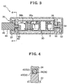
- FIG. 3 is a lateral cross-sectional view of a coating
film transfer tool in accordance with the first embodiment,
in which the tape cassette is shown accommodated within the
casing;
- FIG. 4 is a fragmentary cross-sectional view taken on
plane 4-4 of FIG. 3, showing the transfer shaft of the
cassette supported by a bearing in the casing;
- FIG. 5 is a dismantled perspective view of the coating
film transfer tool of the first embodiment:
- FIG. 6 is a perspective view showing the tape cassette
of the first embodiment;
- FIG. 7A is a longitudinal cross-sectional view of a
casing of a coating film transfer tool in accordance with a
second embodiment of the invention;
- FIG. 7B a lateral cross-sectional view of the casing
of FIG. 7A, taken on plane B-B in FIG. 7A;
- FIG. 8 is a lateral cross-sectional view of a coating
film transfer tool in accordance with the second
embodiment, in which the tape cassette is shown
accommodated within the casing;
- FIG. 9 is a cross-sectional view taken on plane 9-9 of
FIG. 8, showing the transfer shaft of the cassette
supported by a bearing in the casing;
- FIG. 10A is a perspective view of the casing of a
coating film transfer tool in accordance with a third
embodiment of the invention;
- FIG. 10B is a perspective view of a tape cassette to
be received in the casing of FIG. 10A;
- FIG. 11A is a perspective view of an assembled coating
film transfer tool in accordance with the third embodiment;
- FIG. 11B is a cross-sectional view illustrating the
manner in which the transfer shaft of the tape cassette of
FIG. 10B fits into a transfer shaft bearing of FIG. 10A;
- FIG. 12 is a perspective view showing the coating film
transfer tool of the third embodiment in use; and
- FIG. 13 is a longitudinal cross-sectional view of a
conventional coating film transfer tool.
-
Detailed Description
-
The common features of the invention and the prior
art, and the significance of the differences between the
invention and the prior art, can be better appreciated by a
more detailed examination of the prior art. Therefore,
referring first to FIG. 13, a typical conventional coating
film transfer tool 100 comprises a transfer head 106
disposed on a pivot shaft 104 which is rotatably supported
in a casing 102 so that the transfer head can rotate, at
least to a limited degree, relative to the casing. A
pressing transfer part 108, which has a laterally tip
portion, is formed on the transfer head, and protrudes a
short distance beyond the end of the of the transfer head
106.
-
Two tape cores 110a and 110b are provided within
casing 102. Core 110a is a tape supply core carrying a
supply of tape T, which consists of a tape base coated with
a coating film. Core 110b is a take-up core for reeling
the tape base after the coating has been transferred from
the tape base to a coating-receiving surface 112.
-
The transfer tape, which is unwound from the tape
supply core 110a, passes over part 108 with its coated side
facing outward. Before the tape reaches the opposite, or
"return," side of the transfer part 108, the coating is
separated from the tape base and transferred onto the
receiving surface 112 as a result of pressure applied by
the transfer part 108 as part 108 is pressed against and
moved over the receiving surface. Only the tape base
material is reeled around core 110b, the coating having
been removed from the base material at the location of the
transfer part 108.
-
When the coating film transfer tool 100 is used, the
casing 102 is gripped by hand and the pressing transfer
part 108 is drawn in the direction indicated by arrow 114
over the region of surface 112 to which the film is to be
applied. The supply core 110a is rotated in the unwinding
direction by the tangential force exerted on it by tape T
as the transfer part is drawn across surface 112. The
take-up core 110b is rotated in the winding direction as
core 110a rotates in the unwinding direction, by virtue of
mechanical connection, e.g. a driving band, (not shown)
connected between cores 110a and 110b.
-
Because the transfer head 106 is pivoted, pressure
applied to the casing 102 as the device is drawn across
surface 112, maintains the laterally extending tip portion
of transfer part 108 in parallel relationship to surface
112. Consequently, the transfer part applies a uniform
pressure to the tape with the objective of achieving smooth
and complete application of the film to surface 112. Thus,
the pivoting action of the transfer head has an important
advantage in that it produces smoother and more uniform
application of the film to the surface even when the casing
is tilted. However, as pointed out previously, the
pivoting action of the transfer head, also has a
disadvantage because, if the casing 102 is tilted about the
axis of pivot shaft 104, the lengths of tape extending from
tape supply core 110a to transfer part 108 and from
transfer part 108 to take-up core 110b can twist.
Excessive twisting of the tape can cause the tape to
disengage from the pressing transfer part 108, and can even
result in breakage of the tape. Furthermore, twisting of
the tape can result in non-uniform application of the film
to a coating-receiving surface.
-
Referring now to FIG. 1A, the casing 20 of the first
embodiment of the invention comprises a main body 22.
Parts of bearings 26 and 28 are formed on a wall of the
casing respectively adjacent opposite ends of the casing.
A cover 24, as shown in FIGs. 2A and 5, fits onto the main
body 22. The cover has complementary bearing parts which,
in cooperation with the bearing parts in the main body,
form the complete bearings 26 and 28. The bearings are
provided for the purpose of supporting shafts on the tape
cassette which will be housed in the casing.
-
As shown in FIGs. 1B, 2B and 6, the tape cassette 30
comprises a box-shaped main body 32 (FIG. 2B) and a cover
34 (FIGs. 2B and 6). A tape supply core 36a and a take-up
core 36b are rotatably mounted on spindles in the main body
32. The cores are preferably connected to each other for
cooperative rotation by an rubber band 38 in the form of a
loop, although alternatively they can be made mutually
rotatable by gearing.
-
A transfer shaft 40 is fixed within the main body 32
of the cassette. The transfer shaft includes a cylinder-shaped
part 42 within the cassette and a transfer head 44
protruding outwardly from the main body 32 of the cassette.
As will be apparent from FIGs. 1B and 2B, the cylinder-shaped
part 42 of the transfer shaft is located within the
loop of tape extending from the supply reel, and around the
transfer head, to the take-up reel. Apertures are provided
in the walls of the cassette to allow clearance for the
supports of bearing 26 in which the cylinder-shaped part 42
of the transfer shaft is supported rotatably.
-
A pressing transfer part 46, having laterally
extending edge at its tip, is provided on the transfer head
44. A pair of tape guides G (FIGs. 1B and 6) are formed
opposite to each other on the transfer head.
-
The cylindrical part 42 of the transfer shaft 40 is
supported by bearing 26 in casing 20, as illustrated in
FIGs. 3 and 4. The transfer head 44 and the pressing
transfer part 46 of the tape cassette protrude outwardly
from and end portion of the casing, as shown in FIGs. 3 and
5.
-
Further, as illustrated in FIG. 1B, a support shaft 50
protrudes from the end of the cassette opposite to the end
at which the transfer head is located. The support shaft
50 has a cylinder-shaped support shaft 52, which is
engageable in bearing 28 in the main body 22 of the casing,
as shown in FIG. 3. The support shaft 50 has a key-shaped
projection 54 formed at its end. The projection 54, in
cooperation with parts of the bearing 26 limits the
rotation of the cassette within the casing, and also keeps
the support shaft 50 from disengaging from the bearing 28.
-
In the tape cassette 30, a transfer tape T, which
comprises a tape base material and a coating film on the
tape base material, is provided as a coil on core 36a, with
the coating film on the outward face of the base material.
As shown in FIG. 1B, the base material of the tape T passes
over the pressing transfer part 46 at the tip of the
transfer head 44, with its coated side facing outward. At
the location of the pressing transfer part 46, the coating
film is separated from the base as the transfer part is
pressed against and drawn over a surface. The film is
transferred to the surface while the base continues toward,
and is wound onto, the take-up core 36b.
-
As shown in FIG. 1B, the shafts 40 and 50 are aligned
with each other on a common axis SA. The width of the
transfer head 44 is greater than the diameters of shafts 40
and 50. The pressing edge of the transfer part 46 is
offset from axis SA by a distance A (FIG. 1B) in the
direction toward the coating-receiving surface. Therefore
an axis SB extending along the bottom of the transfer part
46 is parallel to, but spaced by a distance A from, the
common axis SA of shafts 40 and 50. The transfer pressing
part and the cassette, therefore, take the form of a crank
with axes SA and SB separated from each other by a distance
A. The distance A can be made relatively large, with the
result that the distance between the casing and the
coating-receiving surface is increased for greater
visibility of the position of the tip of the transfer head
and of the adjacent area of the surface about to be coated.
The fact that the transfer head rotates with the cassette
simplifies the achievement of a relatively large offset for
greater visibility, and also avoids the excessive twisting
that would result from an attempt to achieve improved
visibility by a relatively large offset in a conventional
film transfer tool.
-
Typical dimensions of the coating film transfer tool
are shown in FIGs. 1B, 2B and 8.
-
The coating transfer tool in accordance with the
invention is used in the same way as a conventional
transfer tool. In use, if the casing 20 is rotated
relative to the coating-receiving surface about axis SA,
the pressing transfer part 46, which is rotatable relative
to the casing, can remain in parallel relationship to the
coating-receiving surface. However, unlike the
conventional coating transfer tool of FIG. 13, the transfer
tool of the invention allows the tape cassette to rotate
with the transfer head so that the tape cassette and the
transfer head both rotate together relative to the casing.
Consequently, the tape T will not run aslant and is not
likely to become twisted or break, as is the case with
conventional film transfer tools. The provision of a
cassette rotatable on bearings in a casing not only
prevents twisting of the tape, but also simplifies the
offsetting of the transfer head from its rotation axis for
improved visibility of the location of the tip and the
adjacent coating-receiving surface.
-
In the use of the tool, when the transfer tape is used
up, i.e. when all of the available film has been
transferred, the entire cassette, including the exhausted
tape base can be discarded and replaced as a unit with a
fresh cassette supplied already charged with a new tape.
-
Referring now to FIGs. 7A, 7B, 8 and 9, in the
transfer tool 12 in accordance with the second embodiment
of the invention, a casing 200 receives a tape cassette 30,
which is essentially the same as the tape cassette 30 of
the first embodiment, and is used in the same way.
-
The casing, as shown in FIGs. 7A and 7B, comprises a
main body 22 and a lid 24, as in the first embodiment. Its
bearings 260 and 280 are constituted by cooperating
elements formed on the main body and lid. The second
embodiment differs from the first embodiment in that its
bearings 260 and 280 are formed with projections 262 and
282 respectively, which have convex, curved cross-sections.
-
As shown in FIG. 8, the tape cassette 30 is received
in the casing 200, with its transfer shaft and its support
shaft rotatably supported by the convex bearing surfaces
262 and 282 respectively. As seen in the cross-sectional
view of FIG. 9, the cylindrical parts 42 and 52 of the
transfer shaft and support shaft of the cassette are
supported in bearings formed by cooperating parts of the
casing.
-
In the first embodiment, as shown in FIG. 4, the
cylindrical parts 42 and 52 of shafts 40 and 50 are in
linear contact with the bearing members 26 and 28
respectively. That is, the contact at the bearing surface
takes place essentially along four lines extending parallel
to the axes of the cylindrical parts. In contrast, the
cylindrical parts of the shafts in the second embodiment
are in point contact with the bearing members. That is,
contact takes place essentially at four points (in reality,
very small areas of contact). As a result, the friction
between the shafts and the bearing surfaces is reduced, and
the tape cassette can be rotated in the casing more
smoothly, and with less applied force.
-
The cross-sectional shape of the projections of the
bearing members need not be curved to achieve the effect of
point contact between the bearings and the shafts. For
example, projections having triangular cross-sections can
be used with the same effect. The projections can also be
of various other shapes, such as spherical, triangularly
pyramidal, conical, or in the form of truncated cones.
-
As in the case of the first embodiment, since the tape
cassette 30 is rotated integrally with the transfer tape T
relative to the casing 200, the transfer tape T is not
twisted at all when its film is transferred to the
coating-receiving surface.
-
The structures of the above-described coating film
transfer tools can be further simplified. For example,
FIGs. 10A and 10B, show a coating film transfer tool in
accordance with a third embodiment of the invention, in
which the casing 204 has a U-shaped cross-section and the
tape cassette 304 comprises a plate-shaped main body 320,
on which a tape supply core 36a and a take-up core 36b are
mounted rotatably. The transfer shaft 40 and support shaft
50 are provided on the plate-shaped, main body 320, and
aligned with each other along a common axis which extends
longitudinally through the plate itself. Hooks 266, formed
on the bearing members 264, hold the shafts to the bearing
members and thereby hold the tape cassette in the U-shaped
casing, as shown in FIG. 11B. The cassette can be inserted
into the casing by exerting a lateral force to engage the
shafts in the bearings, taking advantage of elastic
deformation of the hook elements of the bearings.
Moreover, the exhausted cassette can be removed from the
casing by exerting a lateral force in the opposite
direction to disengage the shafts from the bearings.
-
In FIG. 12, which shows the coating film transfer tool
of the third embodiment in use, it is seen that the plate-shaped
body 320 of the tape cassette also functions as a
closure for the casing. As plate 320 is exposed, the tool
should be gripped in such a way as not to hinder the
rotation of plate. Plate 320 and its transfer head can
rotate together about the common axis of shafts 40 and 50
because the common axis of shafts 40 and 50 extends
longitudinally through the plate itself. Consequently the
plate can rotate about the axis of shafts 40 and 50 without
translating upward or downward in the U-shaped casing 204.
-
In the third embodiment, as in the case of the first
and second embodiments, since the tape cassette 304 is
rotated integrally with the transfer tape, the tape is not
twisted in the process transferring a coating film to a
receiving surface, and consequently twisting, breakage of
the tape and other failures are avoided, and the film
coating is applied more smoothly and more effectively.
-
The third embodiment is simpler than the first and
second embodiments, and has fewer parts. Consequently, its
cost of production can be less than the cost of production
of the first two embodiments. Moreover, as the casing of
the third embodiment is not provided with its own lid, the
tape cassette can be removed and replaced more easily.
-
Various modifications can be made to the device
described. For example, a cassette such as the one shown
in FIG. 2B can be installed in a casing having snap-in
bearings of the kind shown in FIG. 11B. Other
modifications may be made to the apparatus and method
described above without departing from the scope of the
invention as defined in the following claims.