EP1059118A2 - Precious metal catalyst supported on a silicate; its use for selective oxidation of carbon monoxide and for hydrogen refining - Google Patents

Precious metal catalyst supported on a silicate; its use for selective oxidation of carbon monoxide and for hydrogen refining Download PDF

Info

Publication number
EP1059118A2
EP1059118A2 EP00111827A EP00111827A EP1059118A2 EP 1059118 A2 EP1059118 A2 EP 1059118A2 EP 00111827 A EP00111827 A EP 00111827A EP 00111827 A EP00111827 A EP 00111827A EP 1059118 A2 EP1059118 A2 EP 1059118A2
Authority
EP
European Patent Office
Prior art keywords
catalyst
carrier
group
gaseous mixture
denotes
Prior art date
Legal status (The legal status is an assumption and is not a legal conclusion. Google has not performed a legal analysis and makes no representation as to the accuracy of the status listed.)
Withdrawn
Application number
EP00111827A
Other languages
German (de)
French (fr)
Other versions
EP1059118A3 (en
Inventor
Shigeru Mitsubishi Heavy Ind. LTD. Nojima
Toshinobu Mitsubishi Heavy Ind. Ltd. Yasutake
Current Assignee (The listed assignees may be inaccurate. Google has not performed a legal analysis and makes no representation or warranty as to the accuracy of the list.)
Mitsubishi Heavy Industries Ltd
Original Assignee
Mitsubishi Heavy Industries Ltd
Priority date (The priority date is an assumption and is not a legal conclusion. Google has not performed a legal analysis and makes no representation as to the accuracy of the date listed.)
Filing date
Publication date
Application filed by Mitsubishi Heavy Industries Ltd filed Critical Mitsubishi Heavy Industries Ltd
Publication of EP1059118A2 publication Critical patent/EP1059118A2/en
Publication of EP1059118A3 publication Critical patent/EP1059118A3/en
Withdrawn legal-status Critical Current

Links

Images

Classifications

    • CCHEMISTRY; METALLURGY
    • C01INORGANIC CHEMISTRY
    • C01BNON-METALLIC ELEMENTS; COMPOUNDS THEREOF; METALLOIDS OR COMPOUNDS THEREOF NOT COVERED BY SUBCLASS C01C
    • C01B3/00Hydrogen; Gaseous mixtures containing hydrogen; Separation of hydrogen from mixtures containing it; Purification of hydrogen; Reversible storage of hydrogen
    • C01B3/50Separation of hydrogen or hydrogen-containing gases from gaseous mixtures, e.g. purification
    • C01B3/56Separation of hydrogen or hydrogen-containing gases from gaseous mixtures, e.g. purification by contacting with solids; Regeneration of used solids
    • C01B3/58Separation of hydrogen or hydrogen-containing gases from gaseous mixtures, e.g. purification by contacting with solids; Regeneration of used solids including a catalytic reaction
    • C01B3/583Separation of hydrogen or hydrogen-containing gases from gaseous mixtures, e.g. purification by contacting with solids; Regeneration of used solids including a catalytic reaction the reaction being the selective oxidation of carbon monoxide
    • BPERFORMING OPERATIONS; TRANSPORTING
    • B01PHYSICAL OR CHEMICAL PROCESSES OR APPARATUS IN GENERAL
    • B01JCHEMICAL OR PHYSICAL PROCESSES, e.g. CATALYSIS OR COLLOID CHEMISTRY; THEIR RELEVANT APPARATUS
    • B01J29/00Catalysts comprising molecular sieves
    • B01J29/04Catalysts comprising molecular sieves having base-exchange properties, e.g. crystalline zeolites
    • BPERFORMING OPERATIONS; TRANSPORTING
    • B01PHYSICAL OR CHEMICAL PROCESSES OR APPARATUS IN GENERAL
    • B01JCHEMICAL OR PHYSICAL PROCESSES, e.g. CATALYSIS OR COLLOID CHEMISTRY; THEIR RELEVANT APPARATUS
    • B01J29/00Catalysts comprising molecular sieves
    • B01J29/04Catalysts comprising molecular sieves having base-exchange properties, e.g. crystalline zeolites
    • B01J29/06Crystalline aluminosilicate zeolites; Isomorphous compounds thereof
    • B01J29/064Crystalline aluminosilicate zeolites; Isomorphous compounds thereof containing iron group metals, noble metals or copper
    • B01J29/068Noble metals
    • CCHEMISTRY; METALLURGY
    • C01INORGANIC CHEMISTRY
    • C01BNON-METALLIC ELEMENTS; COMPOUNDS THEREOF; METALLOIDS OR COMPOUNDS THEREOF NOT COVERED BY SUBCLASS C01C
    • C01B3/00Hydrogen; Gaseous mixtures containing hydrogen; Separation of hydrogen from mixtures containing it; Purification of hydrogen; Reversible storage of hydrogen
    • C01B3/50Separation of hydrogen or hydrogen-containing gases from gaseous mixtures, e.g. purification
    • C01B3/56Separation of hydrogen or hydrogen-containing gases from gaseous mixtures, e.g. purification by contacting with solids; Regeneration of used solids
    • C01B3/58Separation of hydrogen or hydrogen-containing gases from gaseous mixtures, e.g. purification by contacting with solids; Regeneration of used solids including a catalytic reaction
    • BPERFORMING OPERATIONS; TRANSPORTING
    • B01PHYSICAL OR CHEMICAL PROCESSES OR APPARATUS IN GENERAL
    • B01JCHEMICAL OR PHYSICAL PROCESSES, e.g. CATALYSIS OR COLLOID CHEMISTRY; THEIR RELEVANT APPARATUS
    • B01J29/00Catalysts comprising molecular sieves
    • B01J29/03Catalysts comprising molecular sieves not having base-exchange properties
    • B01J29/035Microporous crystalline materials not having base exchange properties, such as silica polymorphs, e.g. silicalites
    • BPERFORMING OPERATIONS; TRANSPORTING
    • B01PHYSICAL OR CHEMICAL PROCESSES OR APPARATUS IN GENERAL
    • B01JCHEMICAL OR PHYSICAL PROCESSES, e.g. CATALYSIS OR COLLOID CHEMISTRY; THEIR RELEVANT APPARATUS
    • B01J29/00Catalysts comprising molecular sieves
    • B01J29/04Catalysts comprising molecular sieves having base-exchange properties, e.g. crystalline zeolites
    • B01J29/046Chromiasilicates; Aluminochromosilicates
    • BPERFORMING OPERATIONS; TRANSPORTING
    • B01PHYSICAL OR CHEMICAL PROCESSES OR APPARATUS IN GENERAL
    • B01JCHEMICAL OR PHYSICAL PROCESSES, e.g. CATALYSIS OR COLLOID CHEMISTRY; THEIR RELEVANT APPARATUS
    • B01J29/00Catalysts comprising molecular sieves
    • B01J29/87Gallosilicates; Aluminogallosilicates; Galloborosilicates
    • BPERFORMING OPERATIONS; TRANSPORTING
    • B01PHYSICAL OR CHEMICAL PROCESSES OR APPARATUS IN GENERAL
    • B01JCHEMICAL OR PHYSICAL PROCESSES, e.g. CATALYSIS OR COLLOID CHEMISTRY; THEIR RELEVANT APPARATUS
    • B01J29/00Catalysts comprising molecular sieves
    • B01J29/88Ferrosilicates; Ferroaluminosilicates
    • BPERFORMING OPERATIONS; TRANSPORTING
    • B01PHYSICAL OR CHEMICAL PROCESSES OR APPARATUS IN GENERAL
    • B01JCHEMICAL OR PHYSICAL PROCESSES, e.g. CATALYSIS OR COLLOID CHEMISTRY; THEIR RELEVANT APPARATUS
    • B01J29/00Catalysts comprising molecular sieves
    • B01J29/89Silicates, aluminosilicates or borosilicates of titanium, zirconium or hafnium
    • CCHEMISTRY; METALLURGY
    • C01INORGANIC CHEMISTRY
    • C01BNON-METALLIC ELEMENTS; COMPOUNDS THEREOF; METALLOIDS OR COMPOUNDS THEREOF NOT COVERED BY SUBCLASS C01C
    • C01B2203/00Integrated processes for the production of hydrogen or synthesis gas
    • C01B2203/04Integrated processes for the production of hydrogen or synthesis gas containing a purification step for the hydrogen or the synthesis gas
    • C01B2203/0435Catalytic purification
    • CCHEMISTRY; METALLURGY
    • C01INORGANIC CHEMISTRY
    • C01BNON-METALLIC ELEMENTS; COMPOUNDS THEREOF; METALLOIDS OR COMPOUNDS THEREOF NOT COVERED BY SUBCLASS C01C
    • C01B2203/00Integrated processes for the production of hydrogen or synthesis gas
    • C01B2203/04Integrated processes for the production of hydrogen or synthesis gas containing a purification step for the hydrogen or the synthesis gas
    • C01B2203/0435Catalytic purification
    • C01B2203/044Selective oxidation of carbon monoxide
    • CCHEMISTRY; METALLURGY
    • C01INORGANIC CHEMISTRY
    • C01BNON-METALLIC ELEMENTS; COMPOUNDS THEREOF; METALLOIDS OR COMPOUNDS THEREOF NOT COVERED BY SUBCLASS C01C
    • C01B2203/00Integrated processes for the production of hydrogen or synthesis gas
    • C01B2203/04Integrated processes for the production of hydrogen or synthesis gas containing a purification step for the hydrogen or the synthesis gas
    • C01B2203/0465Composition of the impurity
    • CCHEMISTRY; METALLURGY
    • C01INORGANIC CHEMISTRY
    • C01BNON-METALLIC ELEMENTS; COMPOUNDS THEREOF; METALLOIDS OR COMPOUNDS THEREOF NOT COVERED BY SUBCLASS C01C
    • C01B2203/00Integrated processes for the production of hydrogen or synthesis gas
    • C01B2203/04Integrated processes for the production of hydrogen or synthesis gas containing a purification step for the hydrogen or the synthesis gas
    • C01B2203/0465Composition of the impurity
    • C01B2203/047Composition of the impurity the impurity being carbon monoxide
    • CCHEMISTRY; METALLURGY
    • C01INORGANIC CHEMISTRY
    • C01BNON-METALLIC ELEMENTS; COMPOUNDS THEREOF; METALLOIDS OR COMPOUNDS THEREOF NOT COVERED BY SUBCLASS C01C
    • C01B2203/00Integrated processes for the production of hydrogen or synthesis gas
    • C01B2203/04Integrated processes for the production of hydrogen or synthesis gas containing a purification step for the hydrogen or the synthesis gas
    • C01B2203/0465Composition of the impurity
    • C01B2203/048Composition of the impurity the impurity being an organic compound

Definitions

  • the present invention relates to a catalyst for selective oxidation of carbon monoxide, a selective removing method of carbon monoxide, a hydrogen refining catalyst for selectively oxidizing CO and CH 3 OH of a gaseous mixture containing H 2 , CH 3 OH, CO and O 2 and a hydrogen refining method for removing CO and CH 3 OH from a gaseous mixture containing H 2 , CH 3 OH and CO.
  • a polymer electrolyte fuel cell permits suppressing generation of a pollutant causing an air pollution, is high in its heat efficiency and, thus, is expected to be used widely as a low temperature operation type fuel cell in a motor car power source, a dispersed power source or the like.
  • a platinum catalyst is used mainly in the electrode of the polymer electrolyte fuel cell. Since the platinum catalyst tends to be poisoned by carbon monoxide (CO), it is necessary remove CO from the fuel gas as much as possible.
  • the fuel gas is manufactured by, for example, reforming the fuel such as methanol by means of steam reforming reaction or a partial oxidation reaction so as to produce a hydrogen gas. Then, CO formed as a by-product in the hydrogen manufacturing reaction is removed by a CO shift reaction of CO + H 2 O ⁇ CO 2 + H 2 .
  • the removal of CO by the CO shift reaction is limited under the restriction in terms of the chemical equilibrium.
  • the resultant gaseous composition contains about 40 to 60% of H 2 , about 10% of CO 2 , about 20% of H 2 O, and about 0.5% of CO.
  • Japanese Patent Disclosure (Kokai) No. 6-296870 discloses a catalyst for cleaning the waste gas. It is taught that the catalyst consists of at least one metal selected from the platinum group elements, which is supported on a crystalline silicate having an X-ray diffraction pattern shown in Table A given in this prior art and represented in terms of the molar ratio of the oxide in a dehydrated state by a chemical formula (1 ⁇ 0.8)R 2 O ⁇ [aM 2 O 3 ⁇ bM'O ⁇ cAl 2 O 3 ] ⁇ ySiO 2 , where R denotes an alkali metal ion and/or hydrogen ion, M denotes an ion of at least one element selected from the group consisting of VIII group elements, rare earth elements, Ti, V, Cr, Nb, Sb and Ga, M' denotes an ion of alkaline earth metals of Mg, Ca, Sr, Ba, 0 ⁇ a, 0 ⁇ b ⁇
  • Reaction (1) given above represents activation of HC
  • reaction (2) represents combustion of HC
  • reaction (3) represents a denitrification
  • reaction (4) represents combustion of CO.
  • An object of the present invention is to provide a catalyst for selectively oxidizing carbon monoxide, the catalyst being capable of selectively oxidizing CO contained in a gaseous mixture containing H 2 , CO and an oxidizing agent of O 2 .
  • Another object is to provide a selective carbon monoxide removing method that permits selectively removing CO from a gaseous mixture containing H 2 and CO.
  • Another object is to provide a hydrogen refining catalyst capable of selectively oxidizing CO and CH 3 OH contained in a gaseous mixture containing H 2 , CO, CH 3 OH and an oxidizing agent of O 2 with a high selective oxidizing capability.
  • Still another object is to provide a hydrogen refining method capable of selectively oxidizing and removing CO and CH 3 OH contained in a gaseous mixture containing H 2 , CO and CH 3 OH with a high removal rate.
  • a selective carbon monoxide oxidizing catalyst capable of selectively oxidizing CO contained in a gaseous mixture containing H 2 , CO and an oxidizing agent of O 2 , comprising a carrier and an active metal consisting of at least one kind of metal selected from the group consisting of Pt, Pd, Ru, Rh and Ir and supported on the carrier, the carrier being a crystalline silicate having the highest to the fifth highest peaks in the powder X-ray diffraction using CuK ⁇ ray in the lattice spacing of 3.65 ⁇ 0.1 ⁇ , 3.75 ⁇ 0.1 ⁇ , 3.85 ⁇ 0.1 ⁇ , 10.0 ⁇ 0.3 ⁇ , and 11.2 ⁇ 0.3 ⁇ , and having the composition represented by formula (1) under a dehydrated state: (1 ⁇ 0.8)R 2 O ⁇ [aM 2 O 3 ⁇ bNO ⁇ cAl 2 O 3 ] ⁇ ySiO 2
  • a selective removing method of carbon monoxide comprising the step of bringing a gaseous mixture containing H 2 , CO and an oxidizing agent of O 2 into contact with a selective oxidizing catalyst of carbon monoxide for selectively oxidizing and removing CO from the gaseous mixture, the selective oxidizing catalyst of carbon monoxide comprising a carrier and an active metal consisting of at least one kind of metal selected from the group consisting of Pt, Pd, Ru, Rh and Ir and supported on the carrier, the carrier being a crystalline silicate having the highest to the fifth highest peaks in the powder X-ray diffraction using CuK ⁇ ray in the lattice spacing of 3.65 ⁇ 0.1 ⁇ , 3.75 ⁇ 0.1 ⁇ , 3.85 ⁇ 0.1 ⁇ , 10.0 ⁇ 0.3 ⁇ , and 11.2 ⁇ 0.3 ⁇ , and having the composition represented by formula (1) under a dehydrated state: (1 ⁇ 0.8)R 2 O ⁇ [aM 2 O 3 ⁇ bNO ⁇ cA
  • a selective removing method of carbon monoxide comprising the steps of:
  • a hydrogen refining catalyst for selectively oxidizing CO and CH 3 OH contained in a gaseous mixture containing H 2 , CO, CH 3 OH and an oxidizing agent of O 2 , the catalyst comprising a carrier and an active species supported on the carrier, the carrier being a crystalline silicate having the highest to the fifth highest peaks in the powder X-ray diffraction using CuK ⁇ ray in the lattice spacing of 3.65 ⁇ 0.1 ⁇ , 3.75 ⁇ 0.1 ⁇ , 3.85 ⁇ 0.1 ⁇ , 10.0 ⁇ 0.3 ⁇ , and 11.2 ⁇ 0.3 ⁇ , and having the composition represented by formula (1) under a dehydrated state: (1 ⁇ 0.8)R 2 O ⁇ [aM 2 O 3 ⁇ bNO ⁇ cAl 2 O 3 ] ⁇ ySiO 2
  • a hydrogen refining catalyst for selectively oxidizing CO and CH 3 OH contained in a gaseous mixture containing H 2 , CO, CH 3 OH and an oxidizing agent of O 2 , comprising a carrier consisting of a silicate and an active species consisting of Pd and supported on the carrier.
  • a hydrogen refining method comprising the step of bringing a gaseous mixture containing H 2 , CO, CH 3 OH and an oxidizing agent of O 2 into contact with a hydrogen refining catalyst so as to selectively oxidize and remove CO and CH 3 OH from the gaseous mixture, the hydrogen refining catalyst comprising a carrier and an active species supported on the carrier, the carrier being a crystalline silicate having the highest to the fifth highest peaks in the powder X-ray diffraction using CuK ⁇ ray in the lattice spacing of 3.65 ⁇ 0.1 ⁇ , 3.75 ⁇ 0.1 ⁇ , 3.85 ⁇ 0.1 ⁇ , 10.0 ⁇ 0.3 ⁇ , and 11.2 ⁇ 0.3 ⁇ , and having the composition represented by formula (1) under a dehydrated state: (1 ⁇ 0.8)R 2 O ⁇ [aM 2 O 3 ⁇ bNO ⁇ cAl 2 O 3 ] ⁇ ySiO 2
  • a hydrogen refining method comprising the steps of:
  • a hydrogen refining method comprising the step of bringing a gaseous mixture containing H 2 , CO, CH 3 OH and an oxidizing agent of O 2 into contact with a hydrogen refining catalyst so as to selectively oxidize CO and CH 3 OH, thus, remove CO and CH 3 OH from the gaseous mixture,
  • a hydrogen refining method comprising the steps of:
  • the selective carbon monoxide oxidizing catalyst of the present invention is capable of selectively oxidizing CO in a gaseous mixture containing H 2 , CO and an oxidizing agent of O 2 .
  • the catalyst comprises a carrier and an active metal consisting of at least one kind of metal selected from Pt, Pd, Ru, Rh and Ir and supported on said carrier, said carrier being a crystalline silicate having the highest to the fifth highest peaks in the powder X-ray diffraction using CuK ⁇ ray in the lattice spacing of 3.65 ⁇ 0.1 ⁇ , 3.75 ⁇ 0.1 ⁇ , 3.85 ⁇ 0.1 ⁇ , 10.0 ⁇ 0.3 ⁇ , and 11.2 ⁇ 0.3 ⁇ , and having the composition represented by formula (1) under a dehydrated state: (1 ⁇ 0.8)R 2 O ⁇ [aM 2 O 3 ⁇ bNO ⁇ cAl 2 O 3 ] ⁇ ySiO 2
  • the crystalline silicate fails to exhibit peaks at the five lattice spacing in the powder X-ray diffraction using a CuK ⁇ ray, or if the peaks, even if exhibited, fail to be any of the highest to the fifth highest peaks, it is impossible to selectively oxidize CO. It is desirable for the crystalline silicate to exhibit the highest to the fifth highest peaks in the powder X-ray diffraction using a CuK ⁇ ray at the five lattice spacing and to exhibit the sixth highest peak et seq. in the lattice spacing of 3.0 ⁇ 0.1 ⁇ , 3.3 ⁇ 0.1 ⁇ , 4.25 ⁇ 0.1 ⁇ , 5.6 ⁇ 0.2 ⁇ , 6.0 ⁇ 0.2 ⁇ , and 6.4 ⁇ 0.2 ⁇ .
  • the crystalline silicate it is more desirable for the crystalline silicate to exhibit the highest to the eleventh highest peaks in the powder X-ray diffraction using a CuK ⁇ ray at the eleven lattice spacing and exhibit the twelfth highest peak et seq. at the lattice spacing of 3.05 ⁇ 0.1 ⁇ , 4.6 ⁇ 0.1 ⁇ , 5.7 ⁇ 0.2 ⁇ , and 6.7 ⁇ 0.2 ⁇ .
  • the selective carbon monoxide oxidizing catalyst of the present invention can be used at 50°C to 250°C.
  • the selective carbon monoxide oxidizing catalyst of the present invention is prepared by dipping, for example, the crystalline silicate noted above in an aqueous solution of a salt of the active metal that is to be supported on the crystalline silicate carrier so as to permit at least one kind of the active metal selected from Pt, Pd, Ru, Rh and Ir to be supported on the crystalline silicate by an ion exchange method or an impregnation method.
  • the selective carbon monoxide oxidizing catalyst of the present invention can be used as it is in the form of a powder or can be held on a porous support.
  • the selective carbon monoxide oxidizing catalyst of the present invention is capable of selectively oxidizing CO contained in a gaseous mixture containing H 2 , CO and an oxidizing agent of O 2 .
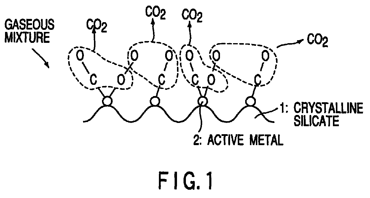
  • the mechanism of the selective carbon monoxide oxidation is considered to be as follows.
  • the particular crystalline silicate specified in the present invention is hydrophobic so as to be unlikely to be affected by water that is present together, has a strong charge density distribution, and has fine pores sized about 6 ⁇ and, thus, adapted for the CO adsorption.
  • the crystalline silicate specified in the present invention is capable of selectively adsorbing a polar substance of CO.
  • any of Pt, Pd, Ru, Rh and Ir supported on the crystalline silicate exhibits a high activity so as to adsorb O 2 contained in the gaseous mixture. As shown in FIG.
  • the method of the present invention is featured in that a gaseous mixture containing H 2 , CO and an oxidizing agent of O 2 is brought into contact with the selective carbon monoxide oxidizing catalyst so as to selectively oxidize CO and, thus, to remove CO from the gaseous mixture.
  • the method of the present invention covers the case where O 2 is added to a gaseous mixture containing H 2 and CO, followed by bringing the gaseous mixture containing the oxidizing agent of O 2 into contact with the selective carbon monoxide oxidizing catalyst.
  • An O 2 gas alone can be added as an oxidizing agent.
  • the air can be added as a gas containing an oxidizing agent.
  • the molar ratio of the oxygen (O 2 ) concentration to the carbon monoxide (CO) concentration (O 2 concentration/CO concentration) to fall within a range of between 0.5 and 5. If the molar ratio noted above is less than 0.5, it may be difficult to remove CO sufficiently from the gaseous mixture. On the other hand, if the molar ratio exceeds 5, the combustion reaction of CO proceeds rapidly. As a result, the catalyst temperature tends to be markedly increased by the combustion heat. In this case, the selectivity of the selective carbon monoxide oxidizing catalyst tends to be lowered. More preferably, the molar ratio of the oxygen concentration to the carbon monoxide concentration should fall within a range of between 0.5 and 3.
  • the carbon monoxide concentration in the gaseous mixture containing H 2 , O 2 and CO is not higher than 4%. If the carbon monoxide concentration exceeds 4%, the catalyst temperature tends to be markedly increased by the combustion heat generated by the combustion reaction of CO. In this case, the selectivity of the selective carbon monoxide oxidizing catalyst tends to be lowered.
  • the CO removing step can be performed by preparing a reactor loaded with a catalyst bed containing the selective carbon monoxide oxidizing catalyst, followed by circulating a gaseous mixture containing H 2 , CO and an oxidizing agent of O 2 through the reactor so as to selectively oxidize CO.
  • the inlet temperature of the catalyst bed It is desirable for the inlet temperature of the catalyst bed to fall within a range of between 50°C and 250°C. If the inlet temperature of the catalyst bed fails to fall within the range noted above, the selectivity of the selective carbon monoxide oxidizing catalyst is lowered, making it difficult to remove CO sufficiently. It is more desirable for the inlet temperature of the catalyst bed to fall within a range of between 60°C and 240°C.
  • the method of the present invention can be used for refining a hydrogen-based fuel gas used in, for example, a polymer electrolyte fuel cell.
  • a hydrogen gas is manufactured by applying a reforming reaction such as a steam reforming reaction or a partial oxidation reaction to methanol or hydrocarbons such as gasoline or methane.
  • a reforming reaction such as a steam reforming reaction or a partial oxidation reaction
  • CO formed by a side reaction is contained in the reformed gas.
  • Carbon monoxide contained in the reformed gas is removed in two stages. In the first stage, the CO concentration is lowered to a desired value by, for example, a CO shift reaction. Then, the residual CO is removed by the method of the present invention.
  • the air or an oxygen gas is supplied to the gaseous material having the CO concentration lowered to a desired level.
  • reaction (A) given below takes place preferentially, though side reactions (a) to (c) given below also take place, so as to obtain a fuel gas for a polymer electrolyte fuel cell containing hydrogen as a main component and having CO removed to a desired level, e.g., 50 ppm or less: 2CO + O 2 ⁇ 2CO 2 2H 2 + O 2 ⁇ 2H 2 O CO 2 + H 2 ⁇ CO + H 2 O CO + 3H 2 ⁇ CH 4 + H 2 O
  • the selective carbon monoxide oxidizing catalyst of the present invention can perform its function at 50 to 250°C and, thus, the refined gas can be used without heat exchange operation as a fuel gas for a polymer electrolyte fuel cell operating at about 80°C, making it possible to simplify the manufacture of the fuel gas for a polymer electrolyte fuel cell.
  • a hydrogen refining catalyst of the present invention will now be described.
  • the hydrogen refining catalyst of the present invention (hereinafter referred to as a "first hydrogen refining catalyst”), comprises a carrier and an active species supported on said carrier, said carrier being a crystalline silicate having the highest to the fifth highest peaks in the powder X-ray diffraction using CuK ⁇ ray in the lattice spacing of 3.65 ⁇ 0.1 ⁇ , 3.75 ⁇ 0.1 ⁇ , 3.85 ⁇ 0.1 ⁇ , 10.0 ⁇ 0.3 ⁇ , and 11.2 ⁇ 0.3 ⁇ , and having the composition represented by formula (1) given previously under a dehydrated state.
  • the catalyst is capable of selectively oxidizing CO and CH 3 OH contained in a gaseous mixture containing H 2 , CO, CH 3 OH and an oxidizing agent of O 2 .
  • the crystalline silicate fails to exhibit peaks at the five lattice spacing in the powder X-ray diffraction using a CuK ⁇ ray, or if the peaks, even if exhibited, fail to be any of the highest to the fifth highest peaks, it is impossible to selectively oxidize CO and CH 3 OH. It is desirable for the crystalline silicate to exhibit the highest to the fifth highest peaks in the powder X-ray diffraction using a CuK ⁇ ray at the five lattice spacing and to exhibit the sixth highest peak et seq. in the lattice spacing of 3.0 ⁇ 0.1 ⁇ , 3.3 ⁇ 0.1 ⁇ , 4.25 ⁇ 0.1 ⁇ , 5.6 ⁇ 0.2 ⁇ , 6.0 ⁇ 0.2 ⁇ , and 6.4 ⁇ 0.2 ⁇ .
  • the crystalline silicate it is more desirable for the crystalline silicate to exhibit the highest to the eleventh highest peaks in the powder X-ray diffraction using a CuK ⁇ ray at the eleven lattice spacing and exhibit the twelfth highest peak et seq. peaks at the lattice spacing of 3.05 ⁇ 0.1 ⁇ , 4.6 ⁇ 0.1 ⁇ , 5.7 ⁇ 0.2 ⁇ , and 6.7 ⁇ 0.2 ⁇ .
  • the active species supported on the carrier prefferably include at least one metal selected from Pt, Pd, Ru, Rh and Ir.
  • Pd is preferred as an active species because Pd permits improving the methanol oxidizing capability, compared with Pt used as an active species.
  • the hydrogen refining catalyst according to another embodiment of the present invention (hereinafter referred to as a "second hydrogen refining catalyst”) comprises a silicate used as a carrier and Pd used as an active species and supported on the carrier.
  • the second hydrogen refining catalyst of the present invention is capable of selectively oxidizing CO and CH 3 OH contained in a gaseous mixture containing H 2 , CO, CH 3 OH and an oxidizing agent of O 2 .
  • the silicate used as the carrier is a salt consisting of silicon dioxide (SiO 2 ) and a metal oxide, and includes, for example, Y-type zeolite, A-type zeolite, mordenite, and the crystalline silicate referred to previously. At least one kind of the silicate selected from among those exemplified above can be used as a carrier of the hydrogen refining catalyst.
  • the hydrogen refining method of the present invention is featured in that a gaseous mixture (or a raw material gas) containing H 2 , CO, CH 3 OH and O 2 is brought into contact with the first or second hydrogen refining catalyst so as to selectively oxidize CO and CH 3 OH and, thus, to remove CO and CH 3 OH from the gaseous mixture.
  • the oxygen gas (O 2 ) contained in the raw material gas is for oxidizing CO and CH 3 OH and, thus, need not be present in the raw material gas together with H 2 , CO and CH 3 OH from the first.
  • the method of the present invention covers the case where an oxidizing agent of O 2 is added to a raw material gas containing H 2 , CO and CH 3 OH, followed by bringing the resultant gaseous mixture into contact with the first or second hydrogen refining catalyst.
  • a oxygen gas alone can be used as the oxidizing agent.
  • the air can be added as a gas containing an oxidizing agent.
  • the molar amount of the O 2 gas contained in the raw material gas should desirably be 0.5 to 20 times as much as the total molar amount of CO and CH 3 OH. If the molar amount of the O 2 gas is less than 0.5 times as much as the total molar amount noted above, it is difficult to achieve a sufficiently high removal rate of CO and CH 3 OH. On the other hand, if the molar amount of the O 2 gas is larger than 20 times as much as the total amount noted above, the combustion reactions of CO and CH 3 OH take place rapidly. As a result, the catalyst temperature tends to be markedly elevated by the combustion heat. It follows that the carbon monoxide selectivity and the methanol selectivity of the catalyst tend to be lowered.
  • the molar amount of the O 2 gas contained in the raw material gas should more desirably be 1.5 to 3 times as much as the total molar amount of CO and CH 3 OH.
  • the CO concentration in the raw material gas is not higher than 4%. If the CO concentration exceeds 4%, the catalyst temperature tends to be markedly elevated by the combustion heat generated by the combustion reaction of CO. As a result, the carbon monoxide selectivity and the methanol selectivity of the catalyst tend to be lowered.
  • the CH 3 OH concentration in the raw material gas is not higher than 2%. If the CH 3 OH concentration exceeds 2%, the catalyst temperature tends to be markedly elevated by the combustion heat generated by the combustion reaction of CH 3 OH. As a result, the carbon monoxide selectivity and the methanol selectivity of the catalyst tend to be lowered.
  • the removing step of CO and CH 3 OH can be performed by preparing a reactor loaded with a catalyst bed containing the first or second hydrogen refining catalyst, followed by circulating a raw material gas containing H 2 , CO, CH 3 OH and an oxidizing agent of O 2 through the reactor so as to selectively oxidize CO and CH 3 OH.
  • the inlet temperature of the catalyst bed should desirably fall within a range of between 50°C and 250°C. If the inlet temperature of the catalyst bed fails to fall within the range noted above, the carbon monoxide selectivity and the methanol selectivity of the catalyst tend to be lowered, making it difficult to achieve a sufficiently high removal rate of CO and CH 3 OH. More preferably, the inlet temperature of the catalyst bed should desirably fall within a range of between 60°C and 240°C.
  • the first hydrogen refining catalyst of the present invention described above comprises a carrier and an active species supported on the carrier, the carrier being a crystalline silicate having the highest to the fifth highest peaks in the powder X-ray diffraction using CuK ⁇ ray in the lattice spacing of 3.65 ⁇ 0.1 ⁇ , 3.75 ⁇ 0.1 ⁇ , 3.85 ⁇ 0.1 ⁇ , 10.0 ⁇ 0.3 ⁇ , and 11.2 ⁇ 0.3 ⁇ , and having the composition represented by formula (1) given previously under a dehydrated state.
  • the crystalline silicate has a porous structure having pores sized about 6 ⁇ , which is adapted for adsorbing CO and CH 3 OH.
  • the crystalline silicate is capable of selectively adsorbing CO and CH 3 OH contained in the raw material gas containing H 2 , O 2 , CO and CH 3 OH. It follows that CO and CH 3 OH can be removed without decreasing the hydrogen amount.
  • CO and CH 3 OH are oxidized by the oxidizing reactions denoted by formulas (B) and (C) given below, respectively: CO + 1/2O 2 ⁇ CO 2 CH 3 OH + 1/2 2 ⁇ CO 2 + H 2 O
  • the first hydrogen refining catalyst of the present invention at least one metal selected from Pt, Pd, Ru, Rh and Ir is used as an active species.
  • the O 2 adsorbing capability of the active species is improved so as to further improve the carbon monoxide selectivity and the methanol selectivity of the catalyst.
  • the molar amount of the O 2 gas is set 0.5 to 20 times as much as the molar amount of the sum of CO and CH 3 OH. In this case, the amount of O 2 required for the oxidation is ensured. At the same time, it is possible to suppress the temperature elevation of the catalyst. It follows that it is possible to further improve the removal rate of CO and CH 3 OH.
  • the second hydrogen refining catalyst of the present invention comprises a carrier consisting of a silicate and an active species consisting of Pd and supported on the carrier. Since the second hydrogen refining catalyst exhibits a high methanol oxidizing activity, it is possible to allow the oxidizing agent of O 2 to selectively oxidize CO and CH 3 OH contained in the raw material gas containing H 2 , O 2 , CO and CH 3 OH.
  • At least one silicate selected from the group consisting of Y-type zeolite, A-type zeolite, mordenite and the crystalline silicate referred to previously is used as a carrier. Since the silicate used as the carrier has a porous structure having pores adapted for adsorbing CO and CH 3 OH, i.e., about 5 to 10 ⁇ , CO and CH 3 OH can be selectively adsorbed. As a result, the selective carbon monoxide oxidizing activity and the selective methanol oxidizing activity of the catalyst can be improved. It follows that the CO concentration and the CH 3 OH concentration can be further lowered so as to further increase the hydrogen purity of the refined gas.
  • the molar amount of the O 2 gas is set 0.5 to 20 times as much as the molar amount of the sum of CO and CH 3 OH. In this case, the amount of O 2 required for the oxidation is ensured. At the same time, it is possible to suppress the temperature elevation of the catalyst. It follows that it is possible to further improve the removal rate of CO and CH 3 OH.
  • the first and second hydrogen refining catalysts of the present invention can be used for refining a hydrogen-based raw material gas, which is a fuel gas of a polymer electrolyte fuel cell.
  • a fuel such as methanol is subjected to, for example, a steam reforming reaction (CH 3 OH + H 2 O ⁇ CO 2 + 3H 2 ) or a partial oxidation reaction so as to obtain a hydrogen gas.
  • methanol is used as the fuel
  • the reformed gas obtained contains a desired material of a hydrogen gas, a by-product of a carbon monoxide gas and the unreacted methanol.
  • methanol tends to be decomposed by the platinum catalyst contained in the electrode of the fuel cell so as to generate a poisoning material of carbon monoxide. It is possible to obtain a hydrogen-based gas having a high purity of hydrogen used as a fuel and low in concentrations of CO and CH 3 OH by adding an oxygen-containing gas to the reformed gas and by allowing CO and CH 3 OH contained in the reformed gas to be selectively oxidized in the presence of the hydrogen refining catalyst of the present invention.
  • Water-glass No. 1 (SiO 2 :30%) was dissolved in an amount of 5,616g in 5,429g of water to prepare solution A.
  • solution A dissolved in 4,175g of water were 718.9g of aluminum sulfate, 110g of ferric chloride, 47.2g of calcium acetate, 262g of sodium chloride, and 2,020g of a concentrated hydrochloric acid to prepare solution B.
  • solutions A and B were supplied at predetermined rates into a container to form precipitation, and the mixture was sufficiently stirred to obtain a slurry having a pH value of 8.
  • the slurry was charged in an amount of 20 liters (L) into an autoclave, followed by introducing 500g of tetrapropyl ammonium bromide into the autoclave to carry out a hydrothermal synthesis at 160°C for 72 hours. After the synthesis, the reaction mixture was washed with water and, then, dried, followed by sintering the mixture at 500°C for 3 hours so as to obtain crystalline silicate 1 having a composition shown in Table 1 under a dehydrated state.
  • the crystalline silicate 1 exhibited in the powder X-ray diffraction using a CuK ⁇ ray the highest to the fifth highest peaks at the lattice spacing of 3.65 ⁇ 0.1 ⁇ , 3.75 ⁇ 0.1 ⁇ , 3.85 ⁇ 0.1 ⁇ , 10.0 ⁇ 0.3 ⁇ , and 11.2 ⁇ 0.3 ⁇ , respectively, the sixth highest to the eleventh highest peaks at the lattice spacing of 3.0 ⁇ 0.1 ⁇ , 3.3 ⁇ 0.1 ⁇ , 4.25 ⁇ 0.1 ⁇ , 5.6 ⁇ 0.2 ⁇ , 6.0 ⁇ 0.2 ⁇ , and 6.4 ⁇ 0.2 ⁇ , and the twelfth highest to the fifteenth highest peaks at the lattice spacing of 3.05 ⁇ 0.1 ⁇ , 4.6 ⁇ 0.1 ⁇ , 5.7 ⁇ 0.2 ⁇ , and 6.7 ⁇ 0.2 ⁇ , respectively.
  • the crystalline silicate 1 was dipped in a 4N NH 4 Cl aqueous solution maintained at 40°C and the solution was kept stirred for 3 hours so as to carry out the NH 4 ion exchange. After the ion exchange, the crystalline silicate 1 was washed and, then, dried at 100°C for 24 hours, followed by sintering the crystalline silicate at 400°C for 3 hours so as to obtain the H-type crystalline silicate 1.
  • a carrier consisting of 100 parts of the H-type crystalline silicate 1 was impregnated with an aqueous solution of chloroplatinic acid (H 2 PtCl 6 ) to permit 1 part by weight of platinum to be supported by the crystalline silicate 1, followed by evaporating the solvent and subsequently performing calcination at 500°C for 5 hours so as to obtain a powdery catalyst.
  • chloroplatinic acid H 2 PtCl 6
  • a binder consisting of 3 parts of alumina sol (Al 2 O 3 :10%) and 55 parts of silica sol (SiO 2 : 20 parts) was added to the resultant powdery catalyst together with 200 parts of water, and the aqueous system was sufficiently stirred to prepare a slurry for wash coating. Then, a monolithic substrate made of cordierite ceramics and having 400 cell lattice meshes was dipped in the slurry. After the substrate was taken out of the slurry, the slurry attached to the substrate was blown off, followed by drying the substrate at 200°C. The coating amount was 150g per liter of the monolithic substrate, and the coated substrate constituted a honeycomb catalyst 1.
  • Crystalline silicates 2 to 12 having the compositions as shown in Table 1 under a dehydrated state were prepared as in preparation of honeycomb catalyst 1 described above, except that cobalt chloride, ruthenium chloride, rhodium chloride, lanthanum chloride, cerium chloride, titanium chloride, vanadium chloride, chromium chloride, antimony chloride, gallium chloride and niobium chloride were added in place of ferric chloride used in preparation of honeycomb catalyst 1 in a molar amount equal to Fe 2 O 3 in terms of oxides.
  • honeycomb catalysts were prepared from the crystalline silicates 2 to 12 as in preparation of honeycomb catalyst 1 described above.
  • Crystalline silicates 13 to 15 having the compositions as shown in Table 1 under a dehydrated state were prepared as in preparation of honeycomb catalyst 1 described above, except that magnesium acetate, strontium acetate and barium acetate were added in place of calcium acetate used in preparation of honeycomb catalyst 1 in a molar amount equal to CaO in terms of oxides.
  • honeycomb catalysts were prepared from the crystalline silicates 13 to 15 as in preparation of honeycomb catalyst 1 described above.
  • a carrier consisting of 100 parts of an H-type crystalline silicate 1 equal to that described previously in conjunction with honeycomb catalyst 1 described previously was impregnated with an aqueous solution of palladium chloride to permit 1 part by weight of Pd to be supported by the carrier, followed by evaporating the solution and drying the carrier impregnated with palladium and subsequently sintering the carrier at 500°C for 5 hours so as to obtain a powdery catalyst.
  • a honeycomb catalyst 16 was prepared from the powdery catalyst by the method equal to that described previously in conjunction with preparation of honeycomb catalyst 1.
  • a carrier consisting of 100 parts of an H-type crystalline silicate 1 equal to that described previously in conjunction with honeycomb catalyst 1 described previously was impregnated with an aqueous solution of rhodium chloride to permit 1 part by weight of Rh to be supported by the carrier, followed by evaporating the solution and drying the carrier impregnated with rhodium and subsequently sintering the carrier at 500°C for 5 hours so as to obtain powdery catalyst.
  • a honeycomb catalyst 17 was prepared from the powdery catalyst by the method equal to that described previously in conjunction with preparation of honeycomb catalyst 1.
  • a carrier consisting of 100 parts of an H-type crystalline silicate 1 equal to that described previously in conjunction with honeycomb catalyst 1 described previously was impregnated with an aqueous solution of ruthenium chloride to permit 1 part by weight of Ru to be supported by the carrier, followed by evaporating the solution and drying the carrier impregnated with ruthenium and subsequently sintering the carrier at 500°C for 5 hours so as to obtain powdery catalyst.
  • a honeycomb catalyst 18 was prepared from the powdery catalyst by the method equal to that described previously in conjunction with preparation of honeycomb catalyst 1.
  • a carrier consisting of 100 parts of an H-type crystalline silicate 1 equal to that described previously in conjunction with honeycomb catalyst 1 described previously was impregnated with an aqueous solution of iridium chloride to permit 1 part by weight of Ir to be supported by the carrier, followed by evaporating the solution and drying the carrier impregnated with iridium and subsequently sintering the carrier at 500°C for 5 hours so as to obtain powdery catalyst.
  • a honeycomb catalyst 19 was prepared from the powdery catalyst by the method equal to that described previously in conjunction with preparation of honeycomb catalyst 1.
  • a ⁇ -Al 2 O 3 powder having a specific surface area of 200 m 2 /g was impregnated with an aqueous solution of chloroplatinic acid (H 2 PtCl 6 ) to permit 1 part by weight of platinum to be supported by the alumina powder so as to obtain a powdery catalyst.
  • a honeycomb catalyst was prepared from the powdery catalyst by a method similar to the method described previously in conjunction with Example 1.
  • a ⁇ -Al 2 O 3 powder having a specific surface area of 200 m 2 /g was impregnated with an aqueous solution of palladium chloride to permit 1 part by weight of Pd to be supported by the alumina powder so as to obtain a powdery catalyst.
  • a honeycomb catalyst was prepared from the powdery catalyst by a method similar to the method described previously in conjunction with Example 1.
  • a ⁇ -Al 2 O 3 powder having a specific surface area of 200 m 2 /g was impregnated with an aqueous solution of rhodium chloride to permit 1 part by weight of Rh to be supported by the alumina powder so as to obtain a powdery catalyst.
  • a honeycomb catalyst was prepared from the powdery catalyst by a method similar to the method described previously in conjunction with Example 1.
  • a ⁇ -Al 2 O 3 powder having a specific surface area of 200 m 2 /g was impregnated with an aqueous solution of ruthenium chloride to permit 1 part by weight of Ru to be supported by the alumina powder so as to obtain a powdery catalyst.
  • a honeycomb catalyst was prepared from the powdery catalyst by a method similar to the method described previously in conjunction with Example 1.
  • a ⁇ -Al 2 O 3 powder having a specific surface area of 200 m 2 /g was impregnated with an aqueous solution of iridium chloride to permit 1 part by weight of Ir to be supported by the alumina powder so as to obtain a powdery catalyst.
  • a honeycomb catalyst was prepared from the powdery catalyst by a method similar to the method described previously in conjunction with Example 1.
  • a CO removal test was conducted by using the honeycomb catalysts prepared in Examples 1 to 19 and Comparative Examples 1 to 5 with respect to a gaseous mixture containing 0.3% of CO, 24% of CO 2 , 20% of H 2 O, 0.3% of O 2 and 55.4% of H 2 .
  • the honeycomb catalyst 3 was loaded in an amount of 15 cc in the tubular reactor 4, as shown in FIG. 2.
  • a sample gas 5 consisting of the gaseous mixture was introduced into the reactor 4 through the inlet port 7 on the left side of the catalyst bed consisting of the honeycomb catalyst 3. While passing through the catalyst bed, the sample gas was subjected to a carbon monoxide oxidizing reaction, with the result that a refined gas 6 was taken out through the outlet port on the right side of the catalyst bed.
  • the surface of the honeycomb catalyst 3 was coated with carbon monoxide selective oxidizing catalyst.
  • the inlet port 7 of the catalyst bed was the porous surface of the honeycomb catalyst 3.
  • GHSV gas hourly space velocity
  • the inlet temperature of the catalyst bed was changed for the CO removal test. Specifically, the CO removal test was conducted under the inlet temperature of the catalyst bed set at 50°C, 80°C, 110°C, 140°C, 170°C, 200°C or 250°C. Further, during the CO removal test, the CO concentration at the outlet port of the catalyst bed was continuously monitored by a CO meter of ND-IR type. The CO concentration was measured when the CO concentration was stabilized. Table 3 shows the CO concentration thus measured.
  • honeycomb catalysts of Examples 1 to 19 permit lowering the CO concentration at the outlet port of the catalyst bed, compared with the honeycomb catalysts of Comparative Examples 1 to 5.
  • Table 3 also shows that the honeycomb catalysts of Examples 1 to 19 permit lowering the CO concentration at the outlet port of the catalyst bed to 50 ppm or less, if the inlet temperature of the catalyst bed is set at suitable values.
  • honeycomb catalysts of Examples 1 to 19 are scarcely affected by the water concentration and excellent in durability.
  • test gases (i) to (iv) given below were prepared, and a CO removal test was conducted for each of these test gases.
  • honeycomb catalysts for Examples 1, 16, 17, 18 and 19 make it possible to lower the carbon monoxide concentration at the outlet port of the catalyst bed to 60 ppm or less if the molar ratio of the O 2 concentration to the CO concentration is set at 5 or less.
  • Example 1 Further, the effects given by the CO concentration was studied with respect to the honeycomb catalyst for Example 1. Specifically, five kinds of test gases (1) to (5) given below were prepared and a CO removal test was conducted for each of these test gases:
  • test gases (1) to (5) the molar ratio of the O 2 concentration to the CO concentration was set at 1.
  • Example 20 As apparent from Table 5, the honeycomb catalyst prepared in Example 1 made it possible to lower the carbon monoxide concentration at the inlet of the catalyst bed (carbon monoxide concentration of the test gas), which was set at 0.3 to 4.0%, to 30 ppm or lower at the outlet port of the catalyst bed.
  • Example 20 Carbon monoxide concentration of the test gas
  • Water-glass No. 1 (SiO 2 :30%) was dissolved in an amount of 5,616g in 5,429g of water to prepare solution A.
  • solution A dissolved in 4,175g of water were 718.9g of aluminum sulfate, 110g of ferric chloride, 47.2g of calcium acetate, 262g of sodium chloride, and 2,020g of a concentrated hydrochloric acid to prepare solution B.
  • solutions A and B were supplied at predetermined rates into a container to form precipitation, and the mixture was sufficiently stirred to obtain a slurry having a pH value of 8.
  • the slurry was charged in an amount of 20 liters (L) into an autoclave, followed by introducing 500g of tetrapropyl ammonium bromide into the autoclave to carry out a hydrothermal synthesis at 160°C for 72 hours. After the synthesis, the reaction mixture was washed with water and, then, dried, followed by sintering the mixture at 500°C for 3 hours so as to obtain crystalline silicate 1 having a composition shown in Table 6 under a dehydrated state.
  • the crystalline silicate 1 was dipped in a 4N NH 4 Cl aqueous solution maintained at 40°C and the solution was kept stirred for 3 hours so as to carry out the NH 4 ion exchange. After the ion exchange, the crystalline silicate 1 was washed and, then, dried at 100°C for 24 hours, followed by sintering the crystalline silicate at 400°C for 3 hours so as to obtain an H-type crystalline silicate 1.
  • a carrier consisting of 100 parts of the H-type crystalline silicate 1 was impregnated with an aqueous solution of chloroplatinic acid (H 2 PtCl 6 ) to permit 1 part by weight of platinum to be supported by the crystalline silicate 1, followed by evaporating the solvent and subsequently performing sintering at 500°C for 5 hours so as to obtain a powdery catalyst.
  • chloroplatinic acid H 2 PtCl 6
  • a binder consisting of 3 parts of alumina sol (Al 2 O 3 :10%) and 55 parts of silica sol (SiO 2 : 20 parts) was added to the resultant powdery catalyst together with 200 parts of water, and the aqueous system was sufficiently stirred to prepare a slurry for wash coating. Then, a monolithic substrate made of cordierite ceramics and having 400 cell lattice meshes was dipped in the slurry. After the substrate was taken out of the slurry, the slurry attached to the substrate was blown off, followed by drying the substrate at 200°C. The coating amount was 100g per liter of the monolithic substrate, and the coated substrate constituted a honeycomb catalyst of Example 20.
  • Crystalline silicates 2 to 12 having the compositions as shown in Table 6 under a dehydrated state were prepared as in preparation of honeycomb catalyst for Example 20, except that cobalt chloride, ruthenium chloride, rhodium chloride, lanthanum chloride, cerium chloride, titanium chloride, vanadium chloride, chromium chloride, antimony chloride, gallium chloride and niobium chloride were added in place of ferric chloride used in preparation of honeycomb catalyst for Example 20 in a molar amount equal to Fe 2 O 3 in terms of oxides.
  • honeycomb catalysts were prepared from the crystalline silicates 2 to 12 as in preparation of honeycomb catalyst for Example 20 described above.
  • Crystalline silicates 13 to 15 having the compositions as shown in Table 6 under a dehydrated state were prepared as in preparation of honeycomb catalyst for Example 20, except that magnesium acetate, strontium acetate and barium acetate were added in place of calcium acetate used in preparation of the honeycomb catalyst in Example 20 in a molar amount equal to CaO in terms of oxides.
  • honeycomb catalysts were prepared from the crystalline silicates 13 to 15 as in preparation of honeycomb catalyst for Example 20 described above.
  • a honeycomb catalyst was prepared as in Example 20, except that palladium chloride was used for the synthesis of the powdery catalyst in place of chloroplatinic acid used in Example 20.
  • a honeycomb catalyst was prepared as in Example 20, except that palladium chloride, rhodium chloride, ruthenium chloride or iridium chloride was used for the synthesis of the powdery catalyst in place of chloroplatinic acid used in Example 20.
  • a carrier consisting of 100 parts of an H-type Y-zeolite (molar ratio of SiO 2 to Al 2 O 3 being 5.2) was impregnated with an aqueous solution of palladium chloride to permit 1 part by weight of Pd to be supported by the carrier, followed by evaporating the solvent and drying the carrier impregnated with palladium and subsequently sintering the carrier at 500°C for 5 hours so as to obtain a powdery catalyst. Further, a honeycomb catalyst was prepared from the powdery catalyst as in Example 20.
  • a carrier consisting of 100 parts of a Ca-type A-zeolite (molar ratio of SiO 2 to Al 2 O 3 being 0.5) was impregnated with an aqueous solution of palladium chloride to permit 1 part by weight of Pd to be supported by the carrier, followed by evaporating the solvent and drying the carrier impregnated with palladium and subsequently sintering the carrier at 500°C for 5 hours so as to obtain a powdery catalyst. Further, a honeycomb catalyst was prepared from the powdery catalyst as in Example 20.
  • a carrier consisting of 100 parts of a H-type mordenite (molar ratio of SiO 2 to Al 2 O 3 being 10) was impregnated with an aqueous solution of palladium chloride to permit 1 part by weight of Pd to be supported by the carrier, followed by evaporating the solvent and drying the carrier impregnated with palladium and subsequently sintering the carrier at 500°C for 5 hours so as to obtain a powdery catalyst. Further, a honeycomb catalyst was prepared from the powdery catalyst as in Example 20.
  • An H-type anatase-type TiO 2 powder was impregnated with an aqueous solution of chloroplatinic acid (H 2 PtCl 6 ) to permit 1 part by weight of platinum to be supported by the TiO 2 powder, followed by evaporating the solvent and, then, sintering the Pt-impregnated TiO 2 powder at 500°C for 5 hours so as to obtain a powdery catalyst.
  • a honeycomb catalyst was prepared from the powdery catalyst as in Example 20.
  • An H-type anatase-type TiO 2 powder was impregnated with an aqueous solution of palladium chloride to permit 1 part by weight of Pd metal to be supported by the TiO 2 powder, followed by evaporating the solvent and, then, sintering the Pd-impregnated TiO 2 powder at 500°C for 5 hours so as to obtain a powdery catalyst.
  • a honeycomb catalyst was prepared from the powdery catalyst as in Example 20.
  • a ⁇ -Al 2 O 3 powder was impregnated with an aqueous solution of chloroplatinic acid (H 2 PtCl 6 ) to permit 1 part by weight of platinum to be supported by the ⁇ -Al 2 O 3 powder, followed by evaporating the solvent and, then, sintering the Pt-impregnated ⁇ -Al 2 O 3 powder at 500°C for 5 hours so as to obtain a powdery catalyst.
  • a honeycomb catalyst was prepared from the powdery catalyst as in Example 20.
  • a ⁇ -Al 2 O 3 powder was impregnated with an aqueous solution of palladium chloride to permit 1 part by weight of Pd to be supported by the ⁇ -alumina powder, followed by evaporating the solvent and, then, sintering the Pd-impregnated ⁇ -Al 2 O 3 powder at 500°C for 5 hours so as to obtain a powdery catalyst.
  • a honeycomb catalyst was prepared from the powdery catalyst as in Example 20. List of tested catalysts Example No.
  • a test for evaluating the selective combustion activities of carbon monoxide and methanol was conducted by loading the honeycomb catalyst prepared in each of Examples 20 to 42 and Comparative Examples 6 to 9 in a cylindrical reactor and by circulating a gaseous mixture containing carbon monoxide and methanol through the reactor.
  • Table 8 shows the results.
  • Table 7 shows the loading amount of the catalyst, the inlet temperature of the catalyst bed, GHSV, the composition of the gaseous mixture, and the circulating rate of the gaseous mixture.
  • the CO concentration of the treated gas at the outlet port of the reactor was continuously monitored by a CO meter of ND-IR type.
  • the methanol concentration of the treated gas at the outlet port of the reactor was measured by a gas chromatograph of an FID detection type.
  • Test conditions for evaluation of selective combustion activities of carbon monoxide and methanol (condition 1) Catalyst loading amount in reactor 30cc Inlet temperature of catalyst bed 70°C, 100°C or 150°C GHSV 15,000h -1 Composition of gaseous mixture CO 0.6%, methanol 0.5%, CO 2 24%, H 2 O 20%, O 2 0.6%, H 2 balance Molar amount of O 2 in gaseous mixture 1.5 mol (Total molar amount of CO and methanol is set at 1) Circulating rate of gaseous mixture 450 NL/h Test conditions for evaluation of selective combustion activities of carbon monoxide and methanol (condition 1) Outlet CO concentration and outlet methanol concentration at various inlet temperature of catalyst bed Examples 70°C 100°C 150°C CO concentration(ppm) methanol concentration(ppm) CO concentration(ppm) methanol concentration(ppm) CO concentration(ppm) methanol concentration(ppm) 20 38 55 7 16 13 18 21 25 43 7 14 15 19 22 33 50 6 11 12 15 23 19 56 6 11 12
  • the catalyst in each of Examples 20 to 39, in which a crystalline silicate having the composition denoted by formula (1) under a dehydrated state is used as the carrier, and the catalyst in each of Examples 40 to 42, in which Pd is supported on a silicate carrier, were capable of lowering the CO concentration in the gaseous mixture to 50 ppm or less and the CH 3 OH concentration to 100 ppm or less in the case where the inlet temperature of the catalyst bed was set at 70 to 150°C.
  • Another test for evaluating the selective combustion activities of carbon monoxide and methanol was conducted by loading the honeycomb catalyst prepared in each of Examples 20 to 42 and Comparative Examples 6 to 9 in a cylindrical reactor and by circulating a gaseous mixture containing carbon monoxide and methanol through the reactor.
  • Table 10 shows the results.
  • Table 9 shows the loading amount of the catalyst, the inlet temperature of the catalyst bed, GHSV, the composition of the gaseous mixture, and the circulating rate of the gaseous mixture.
  • the CO concentration of the treated gas at the outlet port of the reactor was continuously monitored by a CO meter of ND-IR type.
  • the methanol concentration of the treated gas at the outlet port of the reactor was measured by a gas chromatograph of an FID detection type.
  • Test conditions for evaluation of selective combustion activities of carbon monoxide and methanol (condition 2) Catalyst loading amount in reactor 30cc Inlet temperature of catalyst bed 70°C, 100°C or 150°C GHSV 10,000h -1 Composition of gaseous mixture CO 1%, methanol 1%, CO 2 24%, H 2 O 20%, O 2 0.6%, H 2 balance Molar amount of O 2 in gaseous mixture 1.5 mol (Total molar amount of CO and methanol is set at 1) Circulating rate of gaseous mixture 300 NL/h Test conditions for evaluation of selective combustion activities of carbon monoxide and methanol (condition 2) Outlet Co concentration and outlet methanol concentration at various inlet temperature of catalyst bed 50°C 100°C 150°C Examples Co concentration(ppm) methanol concentration(ppm) CO concentration(ppm) methanol concentration(ppm) CO concentration(ppm) methanol concentration(ppm) 20 50 63 18 34 44 55 21 44 54 16 25 41 46 22 39 48 14 21 36 39 23 39 48 14 20 35 38
  • the catalyst in each of Examples 20 to 39 in which a crystalline silicate having the composition denoted by formula (1) under a dehydrated state was used as the carrier, and the catalyst in each of Examples 40 to 42, in which Pd was supported on a silicate carrier, were capable of more lowering the CO concentration and the CH 3 OH concentration in the gaseous mixture than the catalyst in each of Comparative Examples 6 to 9 in the case where the inlet temperature of the catalyst bed was set at 70 to 150°C.
  • the catalyst was of honeycomb structure.
  • the type of the catalyst is not particularly limited in the present invention.
  • the catalyst may be of tablet type or of Raschig ring type.
  • the present invention provides a selective carbon monoxide oxidizing catalyst capable of selectively oxidizing CO of a gaseous mixture containing H 2 , CO and an oxidizing agent of O 2 and a method of selectively removing carbon monoxide capable of selectively removing CO from a gaseous mixture containing H 2 , CO and an oxidizing agent of O 2 .
  • the present invention also provides a hydrogen refining catalyst capable of selectively oxidizing CO and CH 3 OH of a gaseous mixture containing H 2 , CO, CH 3 OH and an oxidizing agent of O 2 and exhibiting an improved selective oxidizing capability and a method of selectively oxidizing and removing CO and CH 3 OH from a gaseous mixture containing H 2 , CO, CH 3 OH and an oxidizing agent of O 2 and exhibiting an improved removal rate.

Landscapes

  • Chemical & Material Sciences (AREA)
  • Organic Chemistry (AREA)
  • Chemical Kinetics & Catalysis (AREA)
  • Engineering & Computer Science (AREA)
  • Combustion & Propulsion (AREA)
  • Inorganic Chemistry (AREA)
  • Crystallography & Structural Chemistry (AREA)
  • Materials Engineering (AREA)
  • Catalysts (AREA)
  • Hydrogen, Water And Hydrids (AREA)
  • Fuel Cell (AREA)

Abstract

Disclosed is a selective carbon monoxide oxidizing catalyst capable of selectively oxidizing CO contained in a gaseous mixture containing H2, CO and an oxidizing agent of O2, comprising a carrier and an active metal (2) consisting of at least one kind of metal selected from the group consisting of Pt, Pd, Ru, Rh and Ir and supported on the carrier, the carrier being a crystalline silicate (1) having the highest to the fifth highest peaks in the powder X-ray diffraction using CuKα ray in the lattice spacing of 3.65±0.1Å, 3.75±0.1Å, 3.85±0.1Å 10.0±0.3Å, and 11.2±0.3Å, and having the composition represented by formula (1) under a dehydrated state: (1±0.8)R2O · [aM2O3 · bNO · cAl2O3] · ySiO2
  • where R denotes at least one element selected from the group consisting of an alkali metal and H, M denotes at least one element selected from the group consisting of VIII group elements, rare earth elements, Ti, V, Cr, Nb, Sb and Ga, N denotes at least one element selected from the group consisting of Mg, Ca, Sr, and Ba, and the molar ratios a, b, c and y are: 0 ≦ a, 0 ≦ b ≦ 20, a+c=1, and 11 ≦ y ≦ 3000.
  • Figure 00000001

    Description

    The present invention relates to a catalyst for selective oxidation of carbon monoxide, a selective removing method of carbon monoxide, a hydrogen refining catalyst for selectively oxidizing CO and CH3OH of a gaseous mixture containing H2, CH3OH, CO and O2 and a hydrogen refining method for removing CO and CH3OH from a gaseous mixture containing H2, CH3OH and CO.
    A polymer electrolyte fuel cell permits suppressing generation of a pollutant causing an air pollution, is high in its heat efficiency and, thus, is expected to be used widely as a low temperature operation type fuel cell in a motor car power source, a dispersed power source or the like. A platinum catalyst is used mainly in the electrode of the polymer electrolyte fuel cell. Since the platinum catalyst tends to be poisoned by carbon monoxide (CO), it is necessary remove CO from the fuel gas as much as possible. The fuel gas is manufactured by, for example, reforming the fuel such as methanol by means of steam reforming reaction or a partial oxidation reaction so as to produce a hydrogen gas. Then, CO formed as a by-product in the hydrogen manufacturing reaction is removed by a CO shift reaction of CO + H2O → CO2 + H2.
    The removal of CO by the CO shift reaction is limited under the restriction in terms of the chemical equilibrium. For example, where a hydrogen gas is manufactured from methanol, followed by applying the CO shift reaction to the hydrogen-containing reaction mixture, the resultant gaseous composition contains about 40 to 60% of H2, about 10% of CO2, about 20% of H2O, and about 0.5% of CO. It should be noted that, in order to prevent the polymer electrolyte fuel cell from being poisoned by CO, it is necessary to lower the CO concentration to 100 ppm or lower. Such being the situation, it is necessary to take measures for further lowering the CO concentration in combination with the CO shift reaction.
    As a measure for removing CO contained in the hydrogen-based raw material gas, studied is a method in which an oxidizing agent of O2 is added to the raw material gas and is brought into contact with the raw material gas so as to selectively oxidize CO contained in the raw material gas.
    In the conventional catalyst, however, almost all the oxygen gas added to the raw material gas reacts with hydrogen, which is the main constituent of the raw material gas, so as to preferentially burn the hydrogen. As a result, CO is left unremoved from the raw material gas.
    On the other hand, Japanese Patent Disclosure (Kokai) No. 6-296870 as claimed discloses a catalyst for cleaning the waste gas. It is taught that the catalyst consists of at least one metal selected from the platinum group elements, which is supported on a crystalline silicate having an X-ray diffraction pattern shown in Table A given in this prior art and represented in terms of the molar ratio of the oxide in a dehydrated state by a chemical formula (1±0.8)R2O · [aM2O3 · bM'O · cAl2O3] · ySiO2, where R denotes an alkali metal ion and/or hydrogen ion, M denotes an ion of at least one element selected from the group consisting of VIII group elements, rare earth elements, Ti, V, Cr, Nb, Sb and Ga, M' denotes an ion of alkaline earth metals of Mg, Ca, Sr, Ba, 0 < a, 0 ≦ b < 20, a+c=1, and 11 < y < 3000.
    This prior art also teaches in columns [0008] to [0009] that the particular waste gas cleaning catalyst permits cleaning the waste gas containing NOx, CO and HC in accordance with reaction formulas (1) to (4) given below: C3H6 + 3/2O2 → 3CH2O CH2O + O2 → CO2 + H2O CH2O + 2NO → N2 + CO2 + H2O CO + 1/2O2 → CO2
    Reaction (1) given above represents activation of HC, reaction (2) represents combustion of HC, reaction (3) represents a denitrification, and reaction (4) represents combustion of CO.
    An object of the present invention is to provide a catalyst for selectively oxidizing carbon monoxide, the catalyst being capable of selectively oxidizing CO contained in a gaseous mixture containing H2, CO and an oxidizing agent of O2.
    Another object is to provide a selective carbon monoxide removing method that permits selectively removing CO from a gaseous mixture containing H2 and CO.
    Another object is to provide a hydrogen refining catalyst capable of selectively oxidizing CO and CH3OH contained in a gaseous mixture containing H2, CO, CH3OH and an oxidizing agent of O2 with a high selective oxidizing capability.
    Still another object is to provide a hydrogen refining method capable of selectively oxidizing and removing CO and CH3OH contained in a gaseous mixture containing H2, CO and CH3OH with a high removal rate.
    According to a first aspect of the present invention, there is provided a selective carbon monoxide oxidizing catalyst capable of selectively oxidizing CO contained in a gaseous mixture containing H2, CO and an oxidizing agent of O2, comprising a carrier and an active metal consisting of at least one kind of metal selected from the group consisting of Pt, Pd, Ru, Rh and Ir and supported on the carrier, the carrier being a crystalline silicate having the highest to the fifth highest peaks in the powder X-ray diffraction using CuKα ray in the lattice spacing of 3.65±0.1Å, 3.75±0.1Å, 3.85±0.1Å, 10.0±0.3Å, and 11.2±0.3Å, and having the composition represented by formula (1) under a dehydrated state: (1±0.8)R2O · [aM2O3 · bNO · cAl2O3] · ySiO2
  • where R denotes at least one element selected from the group consisting of an alkali metal and H, M denotes at least one element selected from the group consisting of VIII group elements, rare earth elements, Ti, V, Cr, Nb, Sb and Ga, N denotes at least one element selected from the group consisting of Mg, Ca, Sr, and Ba, and the molar ratios a, b, c and y are: 0 ≦ a, 0 ≦ b ≦ 20, a+c=1, and 11 ≦ y ≦ 3000.
  • According to a second aspect of the present invention, there is provided a selective removing method of carbon monoxide, comprising the step of bringing a gaseous mixture containing H2, CO and an oxidizing agent of O2 into contact with a selective oxidizing catalyst of carbon monoxide for selectively oxidizing and removing CO from the gaseous mixture, the selective oxidizing catalyst of carbon monoxide comprising a carrier and an active metal consisting of at least one kind of metal selected from the group consisting of Pt, Pd, Ru, Rh and Ir and supported on the carrier, the carrier being a crystalline silicate having the highest to the fifth highest peaks in the powder X-ray diffraction using CuKα ray in the lattice spacing of 3.65±0.1Å, 3.75±0.1Å, 3.85±0.1Å, 10.0±0.3Å, and 11.2±0.3Å, and having the composition represented by formula (1) under a dehydrated state: (1±0.8)R2O · [aM2O3 · bNO · cAl2O3] · ySiO2
  • where R denotes at least one element selected from the group consisting of an alkali metal and H, M denotes at least one element selected from the group consisting of VIII group elements, rare earth elements, Ti, V, Cr, Nb, Sb and Ga, N denotes at least one element selected from the group consisting of Mg, Ca, Sr, and Ba, and the molar ratios a, b, c and y are: 0 ≦ a, 0 ≦ b ≦ 20, a+c=1, and 11 ≦ y ≦ 3000.
  • According to a third aspect of the present invention, there is provided a selective removing method of carbon monoxide, comprising the steps of:
  • preparing a reactor loaded with a catalyst bed housing a selective carbon monoxide oxidizing catalyst; and
  • passing a gaseous mixture containing H2, CO and an oxidizing agent of O2 through the reactor so as to selectively oxidize CO and, thus, remove CO from the
  •    gaseous mixture, wherein:
  • the inlet temperature of the catalyst bed is set at 50 to 250°C; and
  • the selective carbon monoxide oxidizing catalyst comprises a carrier and an active metal consisting of at least one kind of metal selected from the group consisting of Pt, Pd, Ru, Rh and Ir and supported on the carrier, the carrier being a crystalline silicate having the highest to the fifth highest peaks in the powder X-ray diffraction using CuKα ray in the lattice spacing of 3.65±0.1Å, 3.75±0.1Å, 3.85±0.1Å, 10.0±0.3Å, and 11.2±0.3Å, and having the composition represented by formula (1) under a dehydrated state: (1±0.8)R2O · [aM2O3 · bNO · cAl2O3] · ySiO2
  • where R denotes at least one element selected from the group consisting of an alkali metal and H, M denotes at least one element selected from the group consisting of VIII group elements, rare earth elements, Ti, V, Cr, Nb, Sb and Ga, N denotes at least one element selected from the group consisting of Mg, Ca, Sr, and Ba, and the molar ratios a, b, c and y are: 0 ≦ a, 0 ≦ b ≦ 20, a+c=1, and 11 ≦ y ≦ 3000.
  • According to a fourth aspect of the present invention, there is provided a hydrogen refining catalyst for selectively oxidizing CO and CH3OH contained in a gaseous mixture containing H2, CO, CH3OH and an oxidizing agent of O2, the catalyst comprising a carrier and an active species supported on the carrier, the carrier being a crystalline silicate having the highest to the fifth highest peaks in the powder X-ray diffraction using CuKα ray in the lattice spacing of 3.65±0.1Å, 3.75±0.1Å, 3.85±0.1Å, 10.0±0.3Å, and 11.2±0.3Å, and having the composition represented by formula (1) under a dehydrated state: (1±0.8)R2O · [aM2O3 · bNO · cAl2O3] · ySiO2
  • where R denotes at least one element selected from the group consisting of an alkali metal and H, M denotes at least one element selected from the group consisting of VIII group elements, rare earth elements, Ti, V, Cr, Nb, Sb and Ga, N denotes at least one element selected from the group consisting of Mg, Ca, Sr, and Ba, and the molar ratios a, b, c and y are: 0 ≦ a, 0 ≦ b ≦ 20, a+c=1, and 11 ≦ y ≦ 3000.
  • According to a fifth aspect of the present invention, there is provided a hydrogen refining catalyst for selectively oxidizing CO and CH3OH contained in a gaseous mixture containing H2, CO, CH3OH and an oxidizing agent of O2, comprising a carrier consisting of a silicate and an active species consisting of Pd and supported on the carrier.
    According to a sixth aspect of the present invention, there is provided a hydrogen refining method, comprising the step of bringing a gaseous mixture containing H2, CO, CH3OH and an oxidizing agent of O2 into contact with a hydrogen refining catalyst so as to selectively oxidize and remove CO and CH3OH from the gaseous mixture, the hydrogen refining catalyst comprising a carrier and an active species supported on the carrier, the carrier being a crystalline silicate having the highest to the fifth highest peaks in the powder X-ray diffraction using CuKα ray in the lattice spacing of 3.65±0.1Å, 3.75±0.1Å, 3.85±0.1Å, 10.0±0.3Å, and 11.2±0.3Å, and having the composition represented by formula (1) under a dehydrated state: (1±0.8)R2O · [aM2O3 · bNO · cAl2O3] · ySiO2
  • where R denotes at least one element selected from the group consisting of an alkali metal and H, M denotes at least one element selected from the group consisting of VIII group elements, rare earth elements, Ti, V, Cr, Nb, Sb and Ga, N denotes at least one element selected from the group consisting of Mg, Ca, Sr, and Ba, and the molar ratios a, b, c and y are: 0 ≦ a, 0 ≦ b ≦ 20, a+c=1, and 11 ≦ y ≦ 3000.
  • According to a seventh aspect of the present invention, there is provided a hydrogen refining method, comprising the steps of:
  • preparing a reactor loaded with a catalyst bed housing a hydrogen refining catalyst; and
  • passing a gaseous mixture containing H2, CO, CH3OH and an oxidizing agent of O2 through the reactor so as to selectively oxidize CO and CH3OH, thus, remove CO and CH3OH from the gaseous mixture,
    wherein:
  • the inlet temperature of the catalyst bed is set at 50 to 250°C; and
  • the hydrogen refining catalyst comprises a carrier and an active species supported on the carrier, the carrier being a crystalline silicate having the highest to the fifth highest peaks in the powder X-ray diffraction using CuKα ray in the lattice spacing of 3.65±0.1Å, 3.75±0.1Å, 3.85±0.1Å, 10.0±0.3Å, and 11.2±0.3Å, and having the composition represented by formula (1) under a dehydrated state: (1±0.8)R2O · [aM2O3 · bNO · cAl2O3] · ySiO2
  • where R denotes at least one element selected from the group consisting of an alkali metal and H, M denotes at least one element selected from the group consisting of VIII group elements, rare earth elements, Ti, V, Cr, Nb, Sb and Ga, N denotes at least one element selected from the group consisting of Mg, Ca, Sr, and Ba, and the molar ratios a, b, c and y are: 0 ≦ a, 0 ≦ b ≦ 20, a+c=1, and 11 ≦ y ≦ 3000.
  • According to an eighth aspect of the present invention, there is provided a hydrogen refining method, comprising the step of bringing a gaseous mixture containing H2, CO, CH3OH and an oxidizing agent of O2 into contact with a hydrogen refining catalyst so as to selectively oxidize CO and CH3OH, thus, remove CO and CH3OH from the gaseous mixture,
  • wherein the hydrogen refining catalyst comprises a carrier consisting of a silicate and an active species consisting of Pd and supported on the carrier.
  • Further, according to a ninth aspect of the present invention, there is provided a hydrogen refining method, comprising the steps of:
  • preparing a reactor loaded with a catalyst bed housing a hydrogen refining catalyst; and
  • passing a gaseous mixture containing H2, CO, CH3OH and an oxidizing agent of O2 through the reactor so as to selectively oxidize CO and CH3OH, thus, remove CO and CH3OH from the gaseous mixture,
    wherein
  • the inlet temperature of the catalyst bed is set at 50 to 250°C; and
  • the hydrogen refining catalyst comprises a carrier consisting of a silicate and an active species consisting of Pd and supported on the carrier.
  • This summary of the invention does not necessarily describe all necessary features so that the invention may also be a sub-combination of these described features.
    The invention can be more fully understood from the following detailed description when taken in conjunction with the accompanying drawings, in which:
  • FIG. 1 shows a reaction model of a carbon monoxide oxidizing reaction performed in the presence of the carbon monoxide selective oxidizing catalyst of the present invention; and
  • FIG. 2 is a side view showing a reactor used in Example 1 of the present invention.
  • A selective carbon monoxide oxidizing catalyst of the present invention will now be described.
    The selective carbon monoxide oxidizing catalyst of the present invention is capable of selectively oxidizing CO in a gaseous mixture containing H2, CO and an oxidizing agent of O2. The catalyst comprises a carrier and an active metal consisting of at least one kind of metal selected from Pt, Pd, Ru, Rh and Ir and supported on said carrier, said carrier being a crystalline silicate having the highest to the fifth highest peaks in the powder X-ray diffraction using CuKα ray in the lattice spacing of 3.65±0.1Å, 3.75±0.1Å, 3.85±0.1Å, 10.0±0.3Å, and 11.2±0.3Å, and having the composition represented by formula (1) under a dehydrated state: (1±0.8)R2O · [aM2O3 · bNO · cAl2O3] · ySiO2
  • where R denotes at least one element selected from the group consisting of an alkali metal and H, M denotes at least one element selected from the group consisting of VIII group elements, rare earth elements, Ti, V, Cr, Nb, Sb and Ga, N denotes at least one element selected from the group consisting of Mg, Ca, Sr, and Ba, and the molar ratios a, b, c and y are: 0 ≦ a, 0 ≦ b ≦ 20, a+c=1, and 11 ≦ y ≦ 3000.
  • If the crystalline silicate fails to exhibit peaks at the five lattice spacing in the powder X-ray diffraction using a CuKα ray, or if the peaks, even if exhibited, fail to be any of the highest to the fifth highest peaks, it is impossible to selectively oxidize CO. It is desirable for the crystalline silicate to exhibit the highest to the fifth highest peaks in the powder X-ray diffraction using a CuKα ray at the five lattice spacing and to exhibit the sixth highest peak et seq. in the lattice spacing of 3.0±0.1Å, 3.3±0.1Å, 4.25±0.1Å, 5.6±0.2Å, 6.0±0.2Å, and 6.4±0.2Å. It is more desirable for the crystalline silicate to exhibit the highest to the eleventh highest peaks in the powder X-ray diffraction using a CuKα ray at the eleven lattice spacing and exhibit the twelfth highest peak et seq. at the lattice spacing of 3.05±0.1Å, 4.6±0.1Å, 5.7±0.2Å, and 6.7±0.2Å.
    The selective carbon monoxide oxidizing catalyst of the present invention can be used at 50°C to 250°C.
    The selective carbon monoxide oxidizing catalyst of the present invention is prepared by dipping, for example, the crystalline silicate noted above in an aqueous solution of a salt of the active metal that is to be supported on the crystalline silicate carrier so as to permit at least one kind of the active metal selected from Pt, Pd, Ru, Rh and Ir to be supported on the crystalline silicate by an ion exchange method or an impregnation method.
    The selective carbon monoxide oxidizing catalyst of the present invention can be used as it is in the form of a powder or can be held on a porous support.
    The selective carbon monoxide oxidizing catalyst of the present invention is capable of selectively oxidizing CO contained in a gaseous mixture containing H2, CO and an oxidizing agent of O2. The mechanism of the selective carbon monoxide oxidation is considered to be as follows.
    Specifically, the particular crystalline silicate specified in the present invention is hydrophobic so as to be unlikely to be affected by water that is present together, has a strong charge density distribution, and has fine pores sized about 6Å and, thus, adapted for the CO adsorption. As a result, the crystalline silicate specified in the present invention is capable of selectively adsorbing a polar substance of CO. It should also be noted that any of Pt, Pd, Ru, Rh and Ir supported on the crystalline silicate exhibits a high activity so as to adsorb O2 contained in the gaseous mixture. As shown in FIG. 1, carbon monoxide CO adsorbed on, for example, the active metal 2 supported by the crystalline silicate carrier 1 is oxidized by O2 adsorbed on the active metal 2 as denoted by reaction formula (A) given below so as to be released from the oxidizing catalyst as CO2. On the other hand, H2 in the gaseous mixture is not adsorbed on the crystalline silicate carrier 1 so as to pass through the catalyst bed. It follows that CO of the gaseous mixture containing H2, O2 and CO is selectively oxidized, thereby selectively removing CO from the gaseous mixture containing H2, O2 and CO: 2CO + O2 → 2CO2
    The selective carbon monoxide removing method of the present invention will now be described.
    The method of the present invention is featured in that a gaseous mixture containing H2, CO and an oxidizing agent of O2 is brought into contact with the selective carbon monoxide oxidizing catalyst so as to selectively oxidize CO and, thus, to remove CO from the gaseous mixture.
    Since the oxygen gas O2 is for oxidizing CO, O2 need not be present together with H2 and CO from the first. The method of the present invention covers the case where O2 is added to a gaseous mixture containing H2 and CO, followed by bringing the gaseous mixture containing the oxidizing agent of O2 into contact with the selective carbon monoxide oxidizing catalyst. An O2 gas alone can be added as an oxidizing agent. Alternatively, the air can be added as a gas containing an oxidizing agent.
    In the gaseous mixture containing H2, CO and O2, it is desirable for the molar ratio of the oxygen (O2) concentration to the carbon monoxide (CO) concentration (O2 concentration/CO concentration) to fall within a range of between 0.5 and 5. If the molar ratio noted above is less than 0.5, it may be difficult to remove CO sufficiently from the gaseous mixture. On the other hand, if the molar ratio exceeds 5, the combustion reaction of CO proceeds rapidly. As a result, the catalyst temperature tends to be markedly increased by the combustion heat. In this case, the selectivity of the selective carbon monoxide oxidizing catalyst tends to be lowered. More preferably, the molar ratio of the oxygen concentration to the carbon monoxide concentration should fall within a range of between 0.5 and 3.
    It is desirable for the carbon monoxide concentration in the gaseous mixture containing H2, O2 and CO to be not higher than 4%. If the carbon monoxide concentration exceeds 4%, the catalyst temperature tends to be markedly increased by the combustion heat generated by the combustion reaction of CO. In this case, the selectivity of the selective carbon monoxide oxidizing catalyst tends to be lowered.
    The CO removing step can be performed by preparing a reactor loaded with a catalyst bed containing the selective carbon monoxide oxidizing catalyst, followed by circulating a gaseous mixture containing H2, CO and an oxidizing agent of O2 through the reactor so as to selectively oxidize CO.
    It is desirable for the inlet temperature of the catalyst bed to fall within a range of between 50°C and 250°C. If the inlet temperature of the catalyst bed fails to fall within the range noted above, the selectivity of the selective carbon monoxide oxidizing catalyst is lowered, making it difficult to remove CO sufficiently. It is more desirable for the inlet temperature of the catalyst bed to fall within a range of between 60°C and 240°C.
    The method of the present invention can be used for refining a hydrogen-based fuel gas used in, for example, a polymer electrolyte fuel cell.
    To be more specific, in order to obtain the fuel gas, a hydrogen gas is manufactured by applying a reforming reaction such as a steam reforming reaction or a partial oxidation reaction to methanol or hydrocarbons such as gasoline or methane. It should be noted that CO formed by a side reaction is contained in the reformed gas. Carbon monoxide contained in the reformed gas is removed in two stages. In the first stage, the CO concentration is lowered to a desired value by, for example, a CO shift reaction. Then, the residual CO is removed by the method of the present invention. To be more specific, the air or an oxygen gas is supplied to the gaseous material having the CO concentration lowered to a desired level. Also, the resultant gaseous mixture is introduced into the selective carbon monoxide oxidizing catalyst of the present invention. As a result, reaction (A) given below takes place preferentially, though side reactions (a) to (c) given below also take place, so as to obtain a fuel gas for a polymer electrolyte fuel cell containing hydrogen as a main component and having CO removed to a desired level, e.g., 50 ppm or less: 2CO + O2 → 2CO2 2H2 + O2 → 2H2O CO2 + H2 → CO + H2O CO + 3H2 → CH4 + H2O
    As described previously, the selective carbon monoxide oxidizing catalyst of the present invention can perform its function at 50 to 250°C and, thus, the refined gas can be used without heat exchange operation as a fuel gas for a polymer electrolyte fuel cell operating at about 80°C, making it possible to simplify the manufacture of the fuel gas for a polymer electrolyte fuel cell.
    A hydrogen refining catalyst of the present invention will now be described.
    The hydrogen refining catalyst of the present invention (hereinafter referred to as a "first hydrogen refining catalyst"), comprises a carrier and an active species supported on said carrier, said carrier being a crystalline silicate having the highest to the fifth highest peaks in the powder X-ray diffraction using CuKα ray in the lattice spacing of 3.65±0.1Å, 3.75±0.1Å, 3.85±0.1Å, 10.0±0.3Å, and 11.2±0.3Å, and having the composition represented by formula (1) given previously under a dehydrated state. The catalyst is capable of selectively oxidizing CO and CH3OH contained in a gaseous mixture containing H2, CO, CH3OH and an oxidizing agent of O2.
    If the crystalline silicate fails to exhibit peaks at the five lattice spacing in the powder X-ray diffraction using a CuKα ray, or if the peaks, even if exhibited, fail to be any of the highest to the fifth highest peaks, it is impossible to selectively oxidize CO and CH3OH. It is desirable for the crystalline silicate to exhibit the highest to the fifth highest peaks in the powder X-ray diffraction using a CuKα ray at the five lattice spacing and to exhibit the sixth highest peak et seq. in the lattice spacing of 3.0±0.1Å, 3.3±0.1Å, 4.25±0.1Å, 5.6±0.2Å, 6.0±0.2Å, and 6.4±0.2Å. It is more desirable for the crystalline silicate to exhibit the highest to the eleventh highest peaks in the powder X-ray diffraction using a CuKα ray at the eleven lattice spacing and exhibit the twelfth highest peak et seq. peaks at the lattice spacing of 3.05±0.1Å, 4.6±0.1Å, 5.7±0.2Å, and 6.7±0.2Å.
    It is desirable for the active species supported on the carrier to include at least one metal selected from Pt, Pd, Ru, Rh and Ir. Particularly, Pd is preferred as an active species because Pd permits improving the methanol oxidizing capability, compared with Pt used as an active species.
    The hydrogen refining catalyst according to another embodiment of the present invention (hereinafter referred to as a "second hydrogen refining catalyst") comprises a silicate used as a carrier and Pd used as an active species and supported on the carrier. The second hydrogen refining catalyst of the present invention is capable of selectively oxidizing CO and CH3OH contained in a gaseous mixture containing H2, CO, CH3OH and an oxidizing agent of O2.
    The silicate used as the carrier is a salt consisting of silicon dioxide (SiO2) and a metal oxide, and includes, for example, Y-type zeolite, A-type zeolite, mordenite, and the crystalline silicate referred to previously. At least one kind of the silicate selected from among those exemplified above can be used as a carrier of the hydrogen refining catalyst.
    The hydrogen refining method of the present invention is featured in that a gaseous mixture (or a raw material gas) containing H2, CO, CH3OH and O2 is brought into contact with the first or second hydrogen refining catalyst so as to selectively oxidize CO and CH3OH and, thus, to remove CO and CH3OH from the gaseous mixture.
    The oxygen gas (O2) contained in the raw material gas is for oxidizing CO and CH3OH and, thus, need not be present in the raw material gas together with H2, CO and CH3OH from the first. The method of the present invention covers the case where an oxidizing agent of O2 is added to a raw material gas containing H2, CO and CH3OH, followed by bringing the resultant gaseous mixture into contact with the first or second hydrogen refining catalyst. A oxygen gas alone can be used as the oxidizing agent. Alternatively, the air can be added as a gas containing an oxidizing agent.
    The molar amount of the O2 gas contained in the raw material gas should desirably be 0.5 to 20 times as much as the total molar amount of CO and CH3OH. If the molar amount of the O2 gas is less than 0.5 times as much as the total molar amount noted above, it is difficult to achieve a sufficiently high removal rate of CO and CH3OH. On the other hand, if the molar amount of the O2 gas is larger than 20 times as much as the total amount noted above, the combustion reactions of CO and CH3OH take place rapidly. As a result, the catalyst temperature tends to be markedly elevated by the combustion heat. It follows that the carbon monoxide selectivity and the methanol selectivity of the catalyst tend to be lowered. The molar amount of the O2 gas contained in the raw material gas should more desirably be 1.5 to 3 times as much as the total molar amount of CO and CH3OH.
    It is desirable for the CO concentration in the raw material gas to be not higher than 4%. If the CO concentration exceeds 4%, the catalyst temperature tends to be markedly elevated by the combustion heat generated by the combustion reaction of CO. As a result, the carbon monoxide selectivity and the methanol selectivity of the catalyst tend to be lowered.
    It is desirable for the CH3OH concentration in the raw material gas to be not higher than 2%. If the CH3OH concentration exceeds 2%, the catalyst temperature tends to be markedly elevated by the combustion heat generated by the combustion reaction of CH3OH. As a result, the carbon monoxide selectivity and the methanol selectivity of the catalyst tend to be lowered.
    The removing step of CO and CH3OH can be performed by preparing a reactor loaded with a catalyst bed containing the first or second hydrogen refining catalyst, followed by circulating a raw material gas containing H2, CO, CH3OH and an oxidizing agent of O2 through the reactor so as to selectively oxidize CO and CH3OH.
    The inlet temperature of the catalyst bed should desirably fall within a range of between 50°C and 250°C. If the inlet temperature of the catalyst bed fails to fall within the range noted above, the carbon monoxide selectivity and the methanol selectivity of the catalyst tend to be lowered, making it difficult to achieve a sufficiently high removal rate of CO and CH3OH. More preferably, the inlet temperature of the catalyst bed should desirably fall within a range of between 60°C and 240°C.
    The first hydrogen refining catalyst of the present invention described above comprises a carrier and an active species supported on the carrier, the carrier being a crystalline silicate having the highest to the fifth highest peaks in the powder X-ray diffraction using CuKα ray in the lattice spacing of 3.65±0.1Å, 3.75±0.1Å, 3.85±0.1Å, 10.0±0.3Å, and 11.2±0.3Å, and having the composition represented by formula (1) given previously under a dehydrated state. The crystalline silicate has a porous structure having pores sized about 6Å, which is adapted for adsorbing CO and CH3OH. Therefore, the crystalline silicate is capable of selectively adsorbing CO and CH3OH contained in the raw material gas containing H2, O2, CO and CH3OH. It follows that CO and CH3OH can be removed without decreasing the hydrogen amount. Incidentally, CO and CH3OH are oxidized by the oxidizing reactions denoted by formulas (B) and (C) given below, respectively: CO + 1/2O2 → CO2 CH3OH + 1/22 → CO2 + H2O
    In the first hydrogen refining catalyst of the present invention, at least one metal selected from Pt, Pd, Ru, Rh and Ir is used as an active species. In this case, the O2 adsorbing capability of the active species is improved so as to further improve the carbon monoxide selectivity and the methanol selectivity of the catalyst.
    In the raw material gas which contains H2, O2, CO and CH3OH, the molar amount of the O2 gas is set 0.5 to 20 times as much as the molar amount of the sum of CO and CH3OH. In this case, the amount of O2 required for the oxidation is ensured. At the same time, it is possible to suppress the temperature elevation of the catalyst. It follows that it is possible to further improve the removal rate of CO and CH3OH.
    The second hydrogen refining catalyst of the present invention comprises a carrier consisting of a silicate and an active species consisting of Pd and supported on the carrier. Since the second hydrogen refining catalyst exhibits a high methanol oxidizing activity, it is possible to allow the oxidizing agent of O2 to selectively oxidize CO and CH3OH contained in the raw material gas containing H2, O2, CO and CH3OH.
    In the second hydrogen refining catalyst of the present invention, at least one silicate selected from the group consisting of Y-type zeolite, A-type zeolite, mordenite and the crystalline silicate referred to previously is used as a carrier. Since the silicate used as the carrier has a porous structure having pores adapted for adsorbing CO and CH3OH, i.e., about 5 to 10Å, CO and CH3OH can be selectively adsorbed. As a result, the selective carbon monoxide oxidizing activity and the selective methanol oxidizing activity of the catalyst can be improved. It follows that the CO concentration and the CH3OH concentration can be further lowered so as to further increase the hydrogen purity of the refined gas.
    In the raw material gas which contains H2, O2, CO and CH3OH, the molar amount of the O2 gas is set 0.5 to 20 times as much as the molar amount of the sum of CO and CH3OH. In this case, the amount of O2 required for the oxidation is ensured. At the same time, it is possible to suppress the temperature elevation of the catalyst. It follows that it is possible to further improve the removal rate of CO and CH3OH.
    The first and second hydrogen refining catalysts of the present invention can be used for refining a hydrogen-based raw material gas, which is a fuel gas of a polymer electrolyte fuel cell. In order to obtain the hydrogen-based gas, a fuel such as methanol is subjected to, for example, a steam reforming reaction (CH3OH + H2O → CO2 + 3H2) or a partial oxidation reaction so as to obtain a hydrogen gas. If methanol is used as the fuel, the reformed gas obtained contains a desired material of a hydrogen gas, a by-product of a carbon monoxide gas and the unreacted methanol. It should be noted that methanol tends to be decomposed by the platinum catalyst contained in the electrode of the fuel cell so as to generate a poisoning material of carbon monoxide. It is possible to obtain a hydrogen-based gas having a high purity of hydrogen used as a fuel and low in concentrations of CO and CH3OH by adding an oxygen-containing gas to the reformed gas and by allowing CO and CH3OH contained in the reformed gas to be selectively oxidized in the presence of the hydrogen refining catalyst of the present invention.
    Examples:
    The present invention will now be described more in detail with reference to Examples of the present invention.
    Example 1:
    Water-glass No. 1 (SiO2:30%) was dissolved in an amount of 5,616g in 5,429g of water to prepare solution A. On the other hand, dissolved in 4,175g of water were 718.9g of aluminum sulfate, 110g of ferric chloride, 47.2g of calcium acetate, 262g of sodium chloride, and 2,020g of a concentrated hydrochloric acid to prepare solution B. These solutions A and B were supplied at predetermined rates into a container to form precipitation, and the mixture was sufficiently stirred to obtain a slurry having a pH value of 8. The slurry was charged in an amount of 20 liters (L) into an autoclave, followed by introducing 500g of tetrapropyl ammonium bromide into the autoclave to carry out a hydrothermal synthesis at 160°C for 72 hours. After the synthesis, the reaction mixture was washed with water and, then, dried, followed by sintering the mixture at 500°C for 3 hours so as to obtain crystalline silicate 1 having a composition shown in Table 1 under a dehydrated state.
    A powder X-ray diffraction measurement using CuKα ray was applied to the resultant crystalline silicate 1 to obtain lattice spacing (d value) and relative intensities of the highest peak to the 15th highest peak, which are shown in Table 2.
    As apparent from Table 2, the crystalline silicate 1 exhibited in the powder X-ray diffraction using a CuKα ray the highest to the fifth highest peaks at the lattice spacing of 3.65±0.1Å, 3.75±0.1Å, 3.85±0.1Å, 10.0±0.3Å, and 11.2±0.3Å, respectively, the sixth highest to the eleventh highest peaks at the lattice spacing of 3.0±0.1Å, 3.3±0.1Å, 4.25±0.1Å, 5.6±0.2Å, 6.0±0.2Å, and 6.4±0.2Å, and the twelfth highest to the fifteenth highest peaks at the lattice spacing of 3.05±0.1Å, 4.6±0.1Å, 5.7±0.2Å, and 6.7±0.2Å, respectively.
    The crystalline silicate 1 was dipped in a 4N NH4Cl aqueous solution maintained at 40°C and the solution was kept stirred for 3 hours so as to carry out the NH4 ion exchange. After the ion exchange, the crystalline silicate 1 was washed and, then, dried at 100°C for 24 hours, followed by sintering the crystalline silicate at 400°C for 3 hours so as to obtain the H-type crystalline silicate 1.
    Then, a carrier consisting of 100 parts of the H-type crystalline silicate 1 was impregnated with an aqueous solution of chloroplatinic acid (H2PtCl6) to permit 1 part by weight of platinum to be supported by the crystalline silicate 1, followed by evaporating the solvent and subsequently performing calcination at 500°C for 5 hours so as to obtain a powdery catalyst.
    A binder consisting of 3 parts of alumina sol (Al2O3:10%) and 55 parts of silica sol (SiO2: 20 parts) was added to the resultant powdery catalyst together with 200 parts of water, and the aqueous system was sufficiently stirred to prepare a slurry for wash coating. Then, a monolithic substrate made of cordierite ceramics and having 400 cell lattice meshes was dipped in the slurry. After the substrate was taken out of the slurry, the slurry attached to the substrate was blown off, followed by drying the substrate at 200°C. The coating amount was 150g per liter of the monolithic substrate, and the coated substrate constituted a honeycomb catalyst 1.
    Examples 2 to 12:
    Crystalline silicates 2 to 12 having the compositions as shown in Table 1 under a dehydrated state were prepared as in preparation of honeycomb catalyst 1 described above, except that cobalt chloride, ruthenium chloride, rhodium chloride, lanthanum chloride, cerium chloride, titanium chloride, vanadium chloride, chromium chloride, antimony chloride, gallium chloride and niobium chloride were added in place of ferric chloride used in preparation of honeycomb catalyst 1 in a molar amount equal to Fe2O3 in terms of oxides.
    A powder X-ray diffraction measurement using a CuKα ray was applied to each of these crystalline silicates 2 to 12, finding that the lattice spacing and the relative intensities of the highest to the fifteenth highest peaks were as shown in Table 2.
    Then, honeycomb catalysts were prepared from the crystalline silicates 2 to 12 as in preparation of honeycomb catalyst 1 described above.
    Examples 13 to 15:
    Crystalline silicates 13 to 15 having the compositions as shown in Table 1 under a dehydrated state were prepared as in preparation of honeycomb catalyst 1 described above, except that magnesium acetate, strontium acetate and barium acetate were added in place of calcium acetate used in preparation of honeycomb catalyst 1 in a molar amount equal to CaO in terms of oxides.
    A powder X-ray diffraction measurement using a CuKα ray was applied to each of these crystalline silicates 13 to 15, finding that the lattice spacing and the relative intensities of the highest to the fifteenth highest peaks were as shown in Table 2.
    Then, honeycomb catalysts were prepared from the crystalline silicates 13 to 15 as in preparation of honeycomb catalyst 1 described above.
    Example 16:
    A carrier consisting of 100 parts of an H-type crystalline silicate 1 equal to that described previously in conjunction with honeycomb catalyst 1 described previously was impregnated with an aqueous solution of palladium chloride to permit 1 part by weight of Pd to be supported by the carrier, followed by evaporating the solution and drying the carrier impregnated with palladium and subsequently sintering the carrier at 500°C for 5 hours so as to obtain a powdery catalyst. Further, a honeycomb catalyst 16 was prepared from the powdery catalyst by the method equal to that described previously in conjunction with preparation of honeycomb catalyst 1.
    Example 17:
    A carrier consisting of 100 parts of an H-type crystalline silicate 1 equal to that described previously in conjunction with honeycomb catalyst 1 described previously was impregnated with an aqueous solution of rhodium chloride to permit 1 part by weight of Rh to be supported by the carrier, followed by evaporating the solution and drying the carrier impregnated with rhodium and subsequently sintering the carrier at 500°C for 5 hours so as to obtain powdery catalyst. Further, a honeycomb catalyst 17 was prepared from the powdery catalyst by the method equal to that described previously in conjunction with preparation of honeycomb catalyst 1.
    Example 18:
    A carrier consisting of 100 parts of an H-type crystalline silicate 1 equal to that described previously in conjunction with honeycomb catalyst 1 described previously was impregnated with an aqueous solution of ruthenium chloride to permit 1 part by weight of Ru to be supported by the carrier, followed by evaporating the solution and drying the carrier impregnated with ruthenium and subsequently sintering the carrier at 500°C for 5 hours so as to obtain powdery catalyst. Further, a honeycomb catalyst 18 was prepared from the powdery catalyst by the method equal to that described previously in conjunction with preparation of honeycomb catalyst 1.
    Example 19:
    A carrier consisting of 100 parts of an H-type crystalline silicate 1 equal to that described previously in conjunction with honeycomb catalyst 1 described previously was impregnated with an aqueous solution of iridium chloride to permit 1 part by weight of Ir to be supported by the carrier, followed by evaporating the solution and drying the carrier impregnated with iridium and subsequently sintering the carrier at 500°C for 5 hours so as to obtain powdery catalyst. Further, a honeycomb catalyst 19 was prepared from the powdery catalyst by the method equal to that described previously in conjunction with preparation of honeycomb catalyst 1.
    Comparative Example 1:
    A γ-Al2O3 powder having a specific surface area of 200 m2/g was impregnated with an aqueous solution of chloroplatinic acid (H2PtCl6) to permit 1 part by weight of platinum to be supported by the alumina powder so as to obtain a powdery catalyst. A honeycomb catalyst was prepared from the powdery catalyst by a method similar to the method described previously in conjunction with Example 1.
    Comparative Example 2:
    A γ-Al2O3 powder having a specific surface area of 200 m2/g was impregnated with an aqueous solution of palladium chloride to permit 1 part by weight of Pd to be supported by the alumina powder so as to obtain a powdery catalyst. A honeycomb catalyst was prepared from the powdery catalyst by a method similar to the method described previously in conjunction with Example 1.
    Comparative Example 3:
    A γ-Al2O3 powder having a specific surface area of 200 m2/g was impregnated with an aqueous solution of rhodium chloride to permit 1 part by weight of Rh to be supported by the alumina powder so as to obtain a powdery catalyst. A honeycomb catalyst was prepared from the powdery catalyst by a method similar to the method described previously in conjunction with Example 1.
    Comparative Example 4:
    A γ-Al2O3 powder having a specific surface area of 200 m2/g was impregnated with an aqueous solution of ruthenium chloride to permit 1 part by weight of Ru to be supported by the alumina powder so as to obtain a powdery catalyst. A honeycomb catalyst was prepared from the powdery catalyst by a method similar to the method described previously in conjunction with Example 1.
    Comparative Example 5:
    A γ-Al2O3 powder having a specific surface area of 200 m2/g was impregnated with an aqueous solution of iridium chloride to permit 1 part by weight of Ir to be supported by the alumina powder so as to obtain a powdery catalyst. A honeycomb catalyst was prepared from the powdery catalyst by a method similar to the method described previously in conjunction with Example 1.
    Active metal Number of H-type crystalline silicate Composition in dehydrated state of crystalline silicate or composition of carrier
    Example 1 Pt 1 0.5Na2O·0.5H2O[0.2Fe2O3·0.8Al2O3·0.2CaO]25SiO2
    Example 2 Pt 2 0.5Na2O·0.5H2O[0.2Co2O3·0.8Al2O3·0.2CaO]25SiO2
    Example 3 Pt 3 0.5Na2O·0.5H2O[0.2Ru2O3·0.8Al2O3·0.2CaO]25SiO2
    Example 4 Pt 4 0.5Na2O·0.5H2O[0.2Rh2O3·0.8Al2O3·0.2CaO]25SiO2
    Example 5 Pt 5 0.5Na2O·0.5H2O[0.2La2O3·0.8Al2O3·0.2CaO]25SiO2
    Example 6 Pt 6 0.5Na2O·0.5H2O[0.2Ce2O3·0.8Al2O3·0.2CaO]25SiO2
    Example 7 Pt 7 0.5Na2O·0.5H2O[0.2Ti2O3·0.8Al2O3·0.2CaO]25SiO2
    Example 8 Pt 8 0.5Na2O·0.5H2O[0.2V2O3·0.8Al2O3·0.2CaO]25SiO2
    Example 9 Pt 9 0.5Na2O·0.5H2O[0.2Cr2O3·0.8Al2O3·0.2CaO]25SiO2
    Example 10 Pt 10 0.5Na2O·0.5H2O[0.2Sb2O3·0.8Al2O3·0.2CaO]25SiO2
    Example 11 Pt 11 0.5Na2O·0.5H2O[0.2Ga2O3·0.8Al2O3·0.2CaO]25SiO2
    Example 12 Pt 12 0.5Na2O·0.5H2O[0.2Nb2O3·0.8Al2O3·0.2CaO]25SiO2
    Example 13 Pt 13 0.5Na2O·0.5H2O[0.2Fe2O3·0.8Al2O3·0.2MgO]25SiO2
    Example 14 Pt 14 0.5Na2O·0.5H2O[0.2Fe2O3·0.8Al2O3·0.2SrO]25SiO2
    Example 15 Pt 15 0.5Na2O·0.5H2O[0.2Fe2O3·0.8Al2O3·0.2BaO]25SiO2
    Example 16 Pd 1 0.5Na2O·0.5H2O[0.2Fe2O3·0.8Al2O3·0.2CaO]25SiO2
    Example 17 Rh 1 0.5Na2O·0.5H2O[0.2Fe2O3·0.8Al2O3·0.2CaO]25SiO2
    Example 18 Ru 1 0.5Na2O·0.5H2O[0.2Fe2O3·0.8Al2O3·0.2CaO]25SiO2
    Example 19 Ir 1 0.5Na2O·0.5H2O[0.2Fe2O3·0.8Al2O3·0.2CaO]25SiO2
    Comparative Example 1 Pt - Al2O3
    Comparative Example 2 Pd - Al2O3
    Comparative Example 3 Rh - Al2O3
    Comparative Example 4 Ru - Al2O3
    Comparative Example 5 Ir - Al2O3
    Lattice spacing (d value) Relative intensity
    11.2±0.3
    10.0±0.3
    6.7±0.2
    6.4±0.2
    6.0±0.2
    5.7±0.2
    5.6±0.2
    4.6±0.1
    4.25±0.1
    3.85±0.1
    3.75±0.1
    3.65±0.1
    3.3±0.1
    3.05±0.1
    3.0±0.1
    A CO removal test was conducted by using the honeycomb catalysts prepared in Examples 1 to 19 and Comparative Examples 1 to 5 with respect to a gaseous mixture containing 0.3% of CO, 24% of CO2, 20% of H2O, 0.3% of O2 and 55.4% of H2.
    To be more specific, the honeycomb catalyst 3 was loaded in an amount of 15 cc in the tubular reactor 4, as shown in FIG. 2. A sample gas 5 consisting of the gaseous mixture was introduced into the reactor 4 through the inlet port 7 on the left side of the catalyst bed consisting of the honeycomb catalyst 3. While passing through the catalyst bed, the sample gas was subjected to a carbon monoxide oxidizing reaction, with the result that a refined gas 6 was taken out through the outlet port on the right side of the catalyst bed. The surface of the honeycomb catalyst 3 was coated with carbon monoxide selective oxidizing catalyst. The inlet port 7 of the catalyst bed was the porous surface of the honeycomb catalyst 3. GHSV (gas hourly space velocity) was set at 10,000h-1 (gas amount of 150 NL/h). The inlet temperature of the catalyst bed was changed for the CO removal test. Specifically, the CO removal test was conducted under the inlet temperature of the catalyst bed set at 50°C, 80°C, 110°C, 140°C, 170°C, 200°C or 250°C. Further, during the CO removal test, the CO concentration at the outlet port of the catalyst bed was continuously monitored by a CO meter of ND-IR type. The CO concentration was measured when the CO concentration was stabilized. Table 3 shows the CO concentration thus measured.
    Active metal Co concentration at outlet port of catalyst bed at various inlet temperature of catalyst bed (ppm)
    50°C 80°C 110°C 140°C 170°C 200°C 250°C
    Example 1 Pt 28 15 8 17 70 300 1500
    Example 2 Pt 26 13 7 15 65 290 1400
    Example 3 Pt 23 11 6 13 49 270 1320
    Example 4 Pt 20 10 6 12 35 290 1200
    Example 5 Pt 23 11 9 16 34 350 1100
    Example 6 Pt 21 10 7 15 47 290 1400
    Example 7 Pt 22 11 8 14 45 300 1500
    Example 8 Pt 23 10 6 13 39 290 1700
    Example 9 Pt 21 10 7 14 45 300 1800
    Example 10 Pt 20 9 6 14 29 280 1700
    Example 11 Pt 19 12 8 15 36 280 1700
    Example 12 Pt 22 14 7 14 43 280 1600
    Example 13 Pt 21 15 8 15 42 290 1600
    Example 14 Pt 23 16 7 14 42 280 1600
    Example 15 Pt 22 14 7 13 38 250 1500
    Example 16 Pd 45 26 15 20 39 300 2000
    Example 17 Rh 100 45 19 15 15 190 700
    Example 18 Ru 120 29 20 10 6 14 66
    Example 19 Ir 60 30 12 10 18 80 290
    Comparative Example 1 Pt 1200 1600 1700 1800 1900 2500 2900
    Comparative Example 2 Pd 1500 1400 1000 1300 1600 2200 2800
    Comparative Example 3 Rh 2300 2000 1900 1600 1500 2000 2500
    Comparative Example 4 Ru 2400 2300 1800 1600 1400 2000 2300
    Comparative Example 5 Ir 2200 2100 2000 2000 2200 2300 2400
    As apparent from Table 3, the honeycomb catalysts of Examples 1 to 19 permit lowering the CO concentration at the outlet port of the catalyst bed, compared with the honeycomb catalysts of Comparative Examples 1 to 5. Table 3 also shows that the honeycomb catalysts of Examples 1 to 19 permit lowering the CO concentration at the outlet port of the catalyst bed to 50 ppm or less, if the inlet temperature of the catalyst bed is set at suitable values.
    It has also been confirmed that the honeycomb catalysts of Examples 1 to 19 are scarcely affected by the water concentration and excellent in durability.
    The effects given by the concentration of the oxygen gas added was studied with respect to the honeycomb catalysts for Examples 1, 16, 17, 18 and 19. Specifically, four kinds of test gases (i) to (iv) given below were prepared, and a CO removal test was conducted for each of these test gases.
  • (i) Test gas containing 0.3% of CO, 24% of CO2, 20% of H2O, 0.15% of O2, and 55.55% of H2 (molar ratio of O2 concentration to CO concentration: 0.5);
  • (ii) Test gas containing 0.3% of CO, 24% of CO2, 20% of H2O, 0.3% of O2, and 55.4% of H2 (molar ratio of O2 concentration to CO concentration: 1.0);
  • (iii) Test gas containing 0.3% of CO, 24% of CO2, 20% of H2O, 0.5% of O2, and 55.2% of H2 (molar ratio of O2 concentration to CO concentration: 1.7);
  • (iv) Test gas containing 0.3% of CO, 24% of CO2, 20% of H2O, 1.0% of O2, and 54.7% of H2 (molar ratio of O2 concentration to CO concentration: 3.3);
  • During the CO removal test, the catalyst loading amount in the reactor and GHSV (gas hourly space velocity) were set equal to those in the test described previously. Also, the inlet temperatures of the catalyst beds, which were found satisfactory in the test described previously, were employed in this test. Table 4 shows the results of the test.
    CO concentration at outlet port of catalyst bed at various molar ratio (O2/CO)
    Example Active metal Inlet temperature of catalyst bed O2/CO 0.5 O2/CO 1.0 O2/CO 1.7 O2/CO 3.3
    1 Pt 110°C 15 8 16 29
    16 Pd 110°C 38 15 30 60
    17 Rh 140°C 41 13 28 50
    18 Ru 170°C 22 6 14 60
    19 Ir 140°C 23 10 30 50
    As apparent from Table 4, the honeycomb catalysts for Examples 1, 16, 17, 18 and 19 make it possible to lower the carbon monoxide concentration at the outlet port of the catalyst bed to 60 ppm or less if the molar ratio of the O2 concentration to the CO concentration is set at 5 or less.
    Further, the effects given by the CO concentration was studied with respect to the honeycomb catalyst for Example 1. Specifically, five kinds of test gases (1) to (5) given below were prepared and a CO removal test was conducted for each of these test gases:
  • (1) Test gas containing 0.3% of CO, 24% of CO2, 20% of H2O, 0.3% of O2, and 55.4% of H2;
  • (2) Test gas containing 0.6% of CO, 24% of CO2, 20% of H2O, 0.6% of O2, and 54.8% of H2;
  • (3) Test gas containing 1.0% of CO, 24% of CO2, 20% of H2O, 1.0% of O2, and 54% of H2;
  • (4) Test gas containing 2.0% of CO, 24% of CO2, 20% of H2O, 2.0% of O2, and 52% of H2;
  • (5) Test gas containing 4.0% of CO, 24% of CO2, 20% of H2O, 4.0% of O2, and 48% of H2.
  • In each of test gases (1) to (5), the molar ratio of the O2 concentration to the CO concentration was set at 1.
    During the CO removal test, the catalyst loading amount in the reactor and GHSV (gas hourly space velocity) were set as in the test described previously. Also, the inlet temperature of the catalyst bed was set at 110°C or 140°C. Table 5 shows the results.
    Co concentration (ppm) at outlet port of catalyst bed
    Inlet CO concentration of the catalyst bed 0.3% Inlet CO concentration of the catalyst bed 0.6% Inlet CO concentration of the catalyst bed 1.0% Inlet CO concentration of the catalyst bed 2.0% Inlet CO concentration of the catalyst bed 4.0%
    Inlet temperature of the catalyst bed 110°C 8 ppm 8 ppm 11 ppm 13 ppm 15 ppm
    Inlet temperature of the catalyst bed 140°C 17 ppm 19 ppm 21 ppm 23 ppm 24 ppm
    As apparent from Table 5, the honeycomb catalyst prepared in Example 1 made it possible to lower the carbon monoxide concentration at the inlet of the catalyst bed (carbon monoxide concentration of the test gas), which was set at 0.3 to 4.0%, to 30 ppm or lower at the outlet port of the catalyst bed. Example 20:
    Water-glass No. 1 (SiO2:30%) was dissolved in an amount of 5,616g in 5,429g of water to prepare solution A. On the other hand, dissolved in 4,175g of water were 718.9g of aluminum sulfate, 110g of ferric chloride, 47.2g of calcium acetate, 262g of sodium chloride, and 2,020g of a concentrated hydrochloric acid to prepare solution B. These solutions A and B were supplied at predetermined rates into a container to form precipitation, and the mixture was sufficiently stirred to obtain a slurry having a pH value of 8. The slurry was charged in an amount of 20 liters (L) into an autoclave, followed by introducing 500g of tetrapropyl ammonium bromide into the autoclave to carry out a hydrothermal synthesis at 160°C for 72 hours. After the synthesis, the reaction mixture was washed with water and, then, dried, followed by sintering the mixture at 500°C for 3 hours so as to obtain crystalline silicate 1 having a composition shown in Table 6 under a dehydrated state.
    A powder X-ray diffraction measurement using CuKα ray was applied to the resultant crystalline silicate 1 to obtain lattice spacing (d value) and relative intensities of the highest peak to the 15th highest peak, which are shown in Table 2 referred to previously.
    The crystalline silicate 1 was dipped in a 4N NH4Cl aqueous solution maintained at 40°C and the solution was kept stirred for 3 hours so as to carry out the NH4 ion exchange. After the ion exchange, the crystalline silicate 1 was washed and, then, dried at 100°C for 24 hours, followed by sintering the crystalline silicate at 400°C for 3 hours so as to obtain an H-type crystalline silicate 1.
    Then, a carrier consisting of 100 parts of the H-type crystalline silicate 1 was impregnated with an aqueous solution of chloroplatinic acid (H2PtCl6) to permit 1 part by weight of platinum to be supported by the crystalline silicate 1, followed by evaporating the solvent and subsequently performing sintering at 500°C for 5 hours so as to obtain a powdery catalyst.
    A binder consisting of 3 parts of alumina sol (Al2O3:10%) and 55 parts of silica sol (SiO2: 20 parts) was added to the resultant powdery catalyst together with 200 parts of water, and the aqueous system was sufficiently stirred to prepare a slurry for wash coating. Then, a monolithic substrate made of cordierite ceramics and having 400 cell lattice meshes was dipped in the slurry. After the substrate was taken out of the slurry, the slurry attached to the substrate was blown off, followed by drying the substrate at 200°C. The coating amount was 100g per liter of the monolithic substrate, and the coated substrate constituted a honeycomb catalyst of Example 20.
    Examples 21 to 31:
    Crystalline silicates 2 to 12 having the compositions as shown in Table 6 under a dehydrated state were prepared as in preparation of honeycomb catalyst for Example 20, except that cobalt chloride, ruthenium chloride, rhodium chloride, lanthanum chloride, cerium chloride, titanium chloride, vanadium chloride, chromium chloride, antimony chloride, gallium chloride and niobium chloride were added in place of ferric chloride used in preparation of honeycomb catalyst for Example 20 in a molar amount equal to Fe2O3 in terms of oxides.
    A powder X-ray diffraction measurement using a CuKα ray was applied to each of these crystalline silicates 2 to 12, finding that the lattice spacing and the relative intensities of the highest to the fifteenth highest peaks were as shown in Table 2 referred to previously. Then, honeycomb catalysts were prepared from the crystalline silicates 2 to 12 as in preparation of honeycomb catalyst for Example 20 described above.
    Examples 32 to 34:
    Crystalline silicates 13 to 15 having the compositions as shown in Table 6 under a dehydrated state were prepared as in preparation of honeycomb catalyst for Example 20, except that magnesium acetate, strontium acetate and barium acetate were added in place of calcium acetate used in preparation of the honeycomb catalyst in Example 20 in a molar amount equal to CaO in terms of oxides.
    A powder X-ray diffraction measurement using a CuKα ray was applied to each of these crystalline silicates 13 to 15, finding that the lattice spacing and the relative intensities of the highest to the fifteenth highest peaks were as shown in Table 2 referred to previously. Then, honeycomb catalysts were prepared from the crystalline silicates 13 to 15 as in preparation of honeycomb catalyst for Example 20 described above.
    Example 35:
    A honeycomb catalyst was prepared as in Example 20, except that palladium chloride was used for the synthesis of the powdery catalyst in place of chloroplatinic acid used in Example 20.
    Examples 36 to 39:
    A honeycomb catalyst was prepared as in Example 20, except that palladium chloride, rhodium chloride, ruthenium chloride or iridium chloride was used for the synthesis of the powdery catalyst in place of chloroplatinic acid used in Example 20.
    Example 40:
    A carrier consisting of 100 parts of an H-type Y-zeolite (molar ratio of SiO2 to Al2O3 being 5.2) was impregnated with an aqueous solution of palladium chloride to permit 1 part by weight of Pd to be supported by the carrier, followed by evaporating the solvent and drying the carrier impregnated with palladium and subsequently sintering the carrier at 500°C for 5 hours so as to obtain a powdery catalyst. Further, a honeycomb catalyst was prepared from the powdery catalyst as in Example 20.
    Example 41:
    A carrier consisting of 100 parts of a Ca-type A-zeolite (molar ratio of SiO2 to Al2O3 being 0.5) was impregnated with an aqueous solution of palladium chloride to permit 1 part by weight of Pd to be supported by the carrier, followed by evaporating the solvent and drying the carrier impregnated with palladium and subsequently sintering the carrier at 500°C for 5 hours so as to obtain a powdery catalyst. Further, a honeycomb catalyst was prepared from the powdery catalyst as in Example 20.
    Example 42:
    A carrier consisting of 100 parts of a H-type mordenite (molar ratio of SiO2 to Al2O3 being 10) was impregnated with an aqueous solution of palladium chloride to permit 1 part by weight of Pd to be supported by the carrier, followed by evaporating the solvent and drying the carrier impregnated with palladium and subsequently sintering the carrier at 500°C for 5 hours so as to obtain a powdery catalyst. Further, a honeycomb catalyst was prepared from the powdery catalyst as in Example 20.
    Comparative Example 6:
    An H-type anatase-type TiO2 powder was impregnated with an aqueous solution of chloroplatinic acid (H2PtCl6) to permit 1 part by weight of platinum to be supported by the TiO2 powder, followed by evaporating the solvent and, then, sintering the Pt-impregnated TiO2 powder at 500°C for 5 hours so as to obtain a powdery catalyst. A honeycomb catalyst was prepared from the powdery catalyst as in Example 20.
    Comparative Example 7:
    An H-type anatase-type TiO2 powder was impregnated with an aqueous solution of palladium chloride to permit 1 part by weight of Pd metal to be supported by the TiO2 powder, followed by evaporating the solvent and, then, sintering the Pd-impregnated TiO2 powder at 500°C for 5 hours so as to obtain a powdery catalyst. A honeycomb catalyst was prepared from the powdery catalyst as in Example 20.
    Comparative Example 8:
    A γ-Al2O3 powder was impregnated with an aqueous solution of chloroplatinic acid (H2PtCl6) to permit 1 part by weight of platinum to be supported by the γ-Al2O3 powder, followed by evaporating the solvent and, then, sintering the Pt-impregnated γ-Al2O3 powder at 500°C for 5 hours so as to obtain a powdery catalyst. A honeycomb catalyst was prepared from the powdery catalyst as in Example 20.
    Comparative Example 9:
    A γ-Al2O3 powder was impregnated with an aqueous solution of palladium chloride to permit 1 part by weight of Pd to be supported by the γ-alumina powder, followed by evaporating the solvent and, then, sintering the Pd-impregnated γ-Al2O3 powder at 500°C for 5 hours so as to obtain a powdery catalyst. A honeycomb catalyst was prepared from the powdery catalyst as in Example 20.
    List of tested catalysts
    Example No. Active metal Number of H- Composition of crystalline silicate under type crystalline dehydrated state and other carriers used silicate
    20 Pt 1 0.5Na2O·0.5H2O[0.2Fe2O3·0.8Al2O3·0.2CaO]25SiO2
    21 Pt 2 0.5Na2O·0.5H2O[0.2Co2O3·0.8Al2O3·0.2CaO]25SiO2
    22 Pt 3 0.5Na2O·0.5H2O[0.2Ru2O3·0.8Al2O3·0.2CaO]25SiO2
    23 Pt 4 0.5Na2O·0.5H2O[0.2Rh2O3·0.8Al2O3·0.2CaO]25SiO2
    24 Pt 5 0.5Na2O·0.5H2O[0.2La2O3·0.8Al2O3·0.2CaO]25SiO2
    25 Pt 6 0.5Na2O·0.5H2O[0.2Ce2O3·0.8Al2O3·0.2CaO]25SiO2
    26 Pt 7 0.5Na2O·0.5H2O[0.2Ti2O3·0.8Al2O3·0.2CaO]25SiO2
    27 Pt 8 0.5Na2O·0.5H2O[0.2V2O3·0.8Al2O3·0.2CaO]25SiO2
    28 Pt 9 0.5Na2O·0.5H2O[0.2Cr2O3·0.8Al2O3·0.2CaO]25SiO2
    29 Pt 10 0.5Na2O·0.5H2O[0.2Sb2O3·0.8Al2O3·0.2CaO]25SiO2
    30 Pt 11 0.5Na2O·0.5H2O[0.2Ga2O3·0.8Al2O3·0.2CaO]25SiO2
    31 Pt 12 0.5Na2O·0.5H2O[0.2Nb2O3·0.8Al2O3·0.2CaO]25SiO2
    32 Pt 13 0.5Na2O·0.5H2O[0.2Fe2O3·0.8Al2O3·0.2MgO]25SiO2
    33 Pt 14 0.5Na2O·0.5H2O[0.2Fe2O3·0.8Al2O3·0.2SrO]25SiO2
    34 Pt 15 0.5Na2O·0.05H2O[0.2Fe2O3·0.8Al2O3·0.2BaO]25SiO2
    35 Pd 1 0.5Na2O·0.5H2O[0.2Fe2O3·0.8Al2O3·0.2CaO]25SiO2
    36 Pd 1 0.5Na2O·0.5H2O[0.2Fe2O3·0.8Al2O3·0.2CaO]25SiO2
    37 Rh 1 0.5Na2O·0.5H2O[0.2Fe2O3·0.8Al2O3·0.2CaO]25SiO2
    38 Ru 1 0.5Na2O·0.5H2O[0.2Fe2O3·0.8Al2O3·0.2CaO]25SiO2
    39 Ir 1 0.5Na2O·0.5H2O[0.2Fe2O3·0.8Al2O3·0.2CaO]25SiO2
    40 Pd 16 Y-type zeolite (SiO2/Al2O3 molar ratio being 5.2)
    41 Pd 18 A-type zeolite (SiO2/Al2O3 molar ratio being 0.5)
    42 Pd 17 Mordenite (SiO2/Al2O3 molar ratio being 10)
    Comparative Example 6 Pt 20 Anatase-type TiO2
    Comparative Example 7 Pd 20 Anatase-type TiO2
    Comparative Example 8 Pt 19 γ-Al2O3
    Comparative Example 9 Pd 19 γ-Al2O3
    A test for evaluating the selective combustion activities of carbon monoxide and methanol was conducted by loading the honeycomb catalyst prepared in each of Examples 20 to 42 and Comparative Examples 6 to 9 in a cylindrical reactor and by circulating a gaseous mixture containing carbon monoxide and methanol through the reactor. Table 8 shows the results. On the other hand, Table 7 shows the loading amount of the catalyst, the inlet temperature of the catalyst bed, GHSV, the composition of the gaseous mixture, and the circulating rate of the gaseous mixture. The CO concentration of the treated gas at the outlet port of the reactor was continuously monitored by a CO meter of ND-IR type. Also, the methanol concentration of the treated gas at the outlet port of the reactor was measured by a gas chromatograph of an FID detection type.
    Test conditions for evaluation of selective combustion activities of carbon monoxide and methanol (condition 1)
    Catalyst loading amount in reactor 30cc
    Inlet temperature of catalyst bed 70°C, 100°C or 150°C
    GHSV 15,000h-1
    Composition of gaseous mixture CO 0.6%, methanol 0.5%, CO2 24%, H2O 20%, O2 0.6%, H2 balance
    Molar amount of O2 in gaseous mixture 1.5 mol (Total molar amount of CO and methanol is set at 1)
    Circulating rate of gaseous mixture 450 NL/h
    Test conditions for evaluation of selective combustion activities of carbon monoxide and methanol (condition 1)
    Outlet CO concentration and outlet methanol concentration at various inlet temperature of catalyst bed
    Examples 70°C 100°C 150°C
    CO concentration(ppm) methanol concentration(ppm) CO concentration(ppm) methanol concentration(ppm) CO concentration(ppm) methanol concentration(ppm)
    20 38 55 7 16 13 18
    21 25 43 7 14 15 19
    22 33 50 6 11 12 15
    23 19 56 6 11 12 14
    24 23 48 9 13 15 21
    25 22 46 7 16 13 18
    26 35 61 9 22 11 25
    27 23 39 9 18 13 22
    28 21 35 10 17 14 27
    29 18 36 10 19 17 26
    30 29 41 11 25 18 29
    31 25 40 10 23 17 31
    32 31 43 9 16 15 24
    33 28 38 12 22 21 30
    34 29 39 13 21 23 29
    35 35 52 14 27 26 35
    36 38 56 19 31 25 34
    37 30 63 13 17 22 31
    38 36 66 11 32 26 38
    39 29 49 9 19 21 27
    40 42 70 18 33 29 48
    41 40 85 13 40 30 52
    42 45 90 16 56 35 78
    Comparative Example 6 110 660 95 325 125 420
    Comparative Example 7 145 700 108 390 152 490
    Comparative Example 8 190 810 136 460 181 515
    Comparative Example 9 540 1260 365 610 630 750
    As apparent from Table 8, the catalyst in each of Examples 20 to 39, in which a crystalline silicate having the composition denoted by formula (1) under a dehydrated state is used as the carrier, and the catalyst in each of Examples 40 to 42, in which Pd is supported on a silicate carrier, were capable of lowering the CO concentration in the gaseous mixture to 50 ppm or less and the CH3OH concentration to 100 ppm or less in the case where the inlet temperature of the catalyst bed was set at 70 to 150°C.
    On the other hand, in the case of using the catalysts prepared in Comparative Examples 6 to 9, in which an anatase-type TiO2 or γ-Al2O3 was used as a carrier, the CO concentration and the CH3OH concentration at the outlet port of the reactor were found to be higher than those in the case of using the catalysts prepared in Examples 20 to 42.
    Another test for evaluating the selective combustion activities of carbon monoxide and methanol was conducted by loading the honeycomb catalyst prepared in each of Examples 20 to 42 and Comparative Examples 6 to 9 in a cylindrical reactor and by circulating a gaseous mixture containing carbon monoxide and methanol through the reactor. Table 10 shows the results. On the other hand, Table 9 shows the loading amount of the catalyst, the inlet temperature of the catalyst bed, GHSV, the composition of the gaseous mixture, and the circulating rate of the gaseous mixture. The CO concentration of the treated gas at the outlet port of the reactor was continuously monitored by a CO meter of ND-IR type. Also, the methanol concentration of the treated gas at the outlet port of the reactor was measured by a gas chromatograph of an FID detection type.
    Test conditions for evaluation of selective combustion activities of carbon monoxide and methanol (condition 2)
    Catalyst loading amount in reactor 30cc
    Inlet temperature of catalyst bed 70°C, 100°C or 150°C
    GHSV 10,000h-1
    Composition of gaseous mixture CO 1%, methanol 1%, CO2 24%, H2O 20%, O2 0.6%, H2 balance
    Molar amount of O2 in gaseous mixture 1.5 mol (Total molar amount of CO and methanol is set at 1)
    Circulating rate of gaseous mixture 300 NL/h
    Test conditions for evaluation of selective combustion activities of carbon monoxide and methanol (condition 2)
    Outlet Co concentration and outlet methanol concentration at various inlet temperature of catalyst bed
    50°C 100°C 150°C
    Examples Co concentration(ppm) methanol concentration(ppm) CO concentration(ppm) methanol concentration(ppm) CO concentration(ppm) methanol concentration(ppm)
    20 50 63 18 34 44 55
    21 44 54 16 25 41 46
    22 39 48 14 21 36 39
    23 39 48 14 20 35 38
    24 45 58 20 29 43 44
    25 52 61 26 32 47 46
    26 41 59 23 30 55 45
    27 43 55 25 28 41 39
    28 47 57 22 28 40 37
    29 40 49 21 24 40 35
    30 38 44 13 21 35 36
    31 39 48 14 23 37 39
    32 50 65 26 32 41 58
    33 48 58 23 31 34 49
    34 39 46 17 27 33 41
    35 41 48 18 26 30 43
    36 47 53 21 30 41 50
    37 42 50 15 25 31 43
    38 50 60 28 35 40 53
    39 50 68 33 38 45 60
    40 96 99 41 55 88 71
    41 88 98 35 44 69 60
    42 78 81 41 50 68 77
    Comparative Example 6 185 405 150 310 180 360
    Comparative Example 7 200 240 180 220 250 260
    Comparative Example 8 330 450 270 350 360 400
    Comparative Example 9 690 790 520 690 600 750
    As apparent from Table 10, the catalyst in each of Examples 20 to 39, in which a crystalline silicate having the composition denoted by formula (1) under a dehydrated state was used as the carrier, and the catalyst in each of Examples 40 to 42, in which Pd was supported on a silicate carrier, were capable of more lowering the CO concentration and the CH3OH concentration in the gaseous mixture than the catalyst in each of Comparative Examples 6 to 9 in the case where the inlet temperature of the catalyst bed was set at 70 to 150°C.
    In the Examples described above, the catalyst was of honeycomb structure. However, the type of the catalyst is not particularly limited in the present invention. For example, the catalyst may be of tablet type or of Raschig ring type.
    As described above in detail, the present invention provides a selective carbon monoxide oxidizing catalyst capable of selectively oxidizing CO of a gaseous mixture containing H2, CO and an oxidizing agent of O2 and a method of selectively removing carbon monoxide capable of selectively removing CO from a gaseous mixture containing H2, CO and an oxidizing agent of O2.
    The present invention also provides a hydrogen refining catalyst capable of selectively oxidizing CO and CH3OH of a gaseous mixture containing H2, CO, CH3OH and an oxidizing agent of O2 and exhibiting an improved selective oxidizing capability and a method of selectively oxidizing and removing CO and CH3OH from a gaseous mixture containing H2, CO, CH3OH and an oxidizing agent of O2 and exhibiting an improved removal rate.

    Claims (20)

    1. A selective carbon monoxide oxidizing catalyst capable of selectively oxidizing CO contained in a gaseous mixture containing H2, CO and an oxidizing agent of O2, comprising a carrier and an active metal (2) consisting of at least one kind of metal selected from the group consisting of Pt, Pd, Ru, Rh and Ir and supported on said carrier, said carrier being a crystalline silicate (1) having the highest to the fifth highest peaks in the powder X-ray diffraction using CuKα ray in the lattice spacing of 3.65±0.1Å, 3.75±0.1Å, 3.85±0.1Å, 10.0±0.3Å, and 11.2±0.3Å, and said crystalline silicate (1) having the composition represented by formula (1) under a dehydrated state: (1±0.8)R2O · [aM2O3 · bNO · cAl2O3] · ySiO2
      where R denotes at least one element selected from the group consisting of an alkali metal and H, M denotes at least one element selected from the group consisting of VIII group elements, rare earth elements, Ti, V, Cr, Nb, Sb and Ga, N denotes at least one element selected from the group consisting of Mg, Ca, Sr, and Ba, and the molar ratios a, b, c and y are: 0 ≦ a, 0 ≦ b ≦ 20, a+c=1, and 11 ≦ y ≦ 3000.
    2. The selective carbon monoxide oxidizing catalyst according to claim 1, characterized in that said crystalline silicate (1) exhibits the highest to the eleventh highest peaks in the powder X-ray diffraction using CuKα ray in the lattice spacing of 3.0±0.1Å, 3.3±0.1Å, 3.65±0.1Å, 3.75±0.1Å, and 3.85±0.1Å, 4.25±0.1Å, 5.6±0.2Å, 6.0±0.2Å, 6.4±0.2Å, 10.0±0.3Å,and 11.2±0.3Å, respectively.
    3. A selective removing method of carbon monoxide, comprising the step of bringing a gaseous mixture containing H2, CO and an oxidizing agent of O2 into contact with a selective oxidizing catalyst of carbon monoxide for selectively oxidizing and removing CO from said gaseous mixture, said selective oxidizing catalyst of carbon monoxide comprising a carrier and an active metal (2) consisting of at least one kind of metal selected from the group consisting of Pt, Pd, Ru, Rh and Ir and supported on said carrier, said carrier being a crystalline silicate (1) having the highest to the fifth highest peaks in the powder X-ray diffraction using CuKα ray in the lattice spacing of 3.65±0.1Å, 3.75±0.1Å, 3.85±0.1Å, 10.0±0.3Å, and 11.2±0.3Å, and said crystalline silicate (1) having the composition represented by formula (1) under a dehydrated state: (1±0.8)R2O · [aM2O3 · bNO · cAl2O3] · ySiO2
      where R denotes at least one element selected from the group consisting of an alkali metal and H, M denotes at least one element selected from the group consisting of VIII group elements, rare earth elements, Ti, V, Cr, Nb, Sb and Ga, N denotes at least one element selected from the group consisting of Mg, Ca, Sr, and Ba, and the molar ratios a, b, c and y are: 0 ≦ a, 0 ≦ b ≦ 20, a+c=1, and 11 ≦ y ≦ 3000.
    4. The selective removing method of carbon monoxide according to claim 3, characterized in that the molar ratio of the oxygen concentration to the carbon monoxide concentration (O2 concentration/carbon monoxide concentration) in said gaseous mixture falls within a range of between 0.5 and 5.
    5. The selective removing method of carbon monoxide according to claim 3, characterized in that the carbon monoxide concentration in said gaseous mixture is not higher than 4%.
    6. A selective removing method of carbon monoxide, comprising the steps of:
      preparing a reactor (4) loaded with a catalyst bed (3) housing a selective carbon monoxide oxidizing catalyst; and
      passing a gaseous mixture (5) containing H2, CO and an oxidizing agent of O2 through said reactor so as to selectively oxidize CO and, thus, remove CO from said gaseous mixture,
      wherein:
      the inlet temperature of said catalyst bed is set at 50 to 250°C; and
      said selective carbon monoxide oxidizing catalyst comprises a carrier and an active metal consisting of at least one kind of metal selected from the group consisting of Pt, Pd, Ru, Rh and Ir and supported on said carrier, said carrier being a crystalline silicate having the highest to the fifth highest peaks in the powder X-ray diffraction using CuKα ray in the lattice spacing of 3.65±0.1Å, 3.75±0.1Å, 3.85±0.1Å, 10.0±0.3Å, and 11.2±0.3Å, and said crystalline silicate having the composition represented by formula (1) under a dehydrated state: (1±0.8)R2O · [aM2O3 · bNO · cAl2O3] · ySiO2
      where R denotes at least one element selected from the group consisting of an alkali metal and H, M denotes at least one element selected from the group consisting of VIII group elements, rare earth elements, Ti, V, Cr, Nb, Sb and Ga, N denotes at least one element selected from the group consisting of Mg, Ca, Sr, and Ba, and the molar ratios a, b, c and y are: 0 ≦ a, 0 ≦ b ≦ 20, a+c=1, and 11 ≦ y ≦ 3000.
    7. A hydrogen refining catalyst for selectively oxidizing CO and CH3OH contained in a gaseous mixture containing H2, CO, CH3OH and an oxidizing agent of O2, said catalyst comprising a carrier and an active species supported on said carrier, said carrier being a crystalline silicate having the highest to the fifth highest peaks in the powder X-ray diffraction using CuKα ray in the lattice spacing of 3.65±0.1Å, 3.75±0.1Å, 3.85±0.1Å, 10.0±0.3Å, and 11.2±0.3Å, and said crystalline silicate having the composition represented by formula (1) under a dehydrated state: (1±0.8)R2O · [aM2O3 · bNO · cAl2O3] · ySiO2
      where R denotes at least one element selected from the group consisting of an alkali metal and H, M denotes at least one element selected from the group consisting of VIII group elements, rare earth elements, Ti, V, Cr, Nb, Sb and Ga, N denotes at least one element selected from the group consisting of Mg, Ca, Sr, and Ba, and the molar ratios a, b, c and y are: 0 ≦ a, 0 ≦ b ≦ 20, a+c=1, and 11 ≦ y ≦ 3000.
    8. The hydrogen refining catalyst according to claim 7, characterized in that said active species consists of at least one metal selected from the group consisting of Pt, Pd, Ru, Rh and Ir.
    9. A hydrogen refining catalyst for selectively oxidizing CO and CH3OH contained in a gaseous mixture containing H2, CO, CH3OH and an oxidizing agent of O2, comprising a carrier consisting of a silicate and an active species consisting of Pd and supported on said carrier.
    10. The hydrogen refining catalyst according to claim 9, characterized in that said carrier consists of at least one silicate selected from the group consisting of Y-type zeolite, A-type zeolite, mordenite and a crystalline silicate, said crystalline silicate having the highest to the fifth highest peaks in the powder X-ray diffraction using CuKα ray in the lattice spacing of 3.65±0.1Å, 3.75±0.1Å, 3.85±0.1Å, 10.0±0.3Å, and 11.2±0.3Å, and said crystalline silicate having the composition represented by formula (1) under a dehydrated state: (1±0.8)R2O · [aM2O3 · bNO · cAl2O3] · ySiO2
      where R denotes at least one element selected from the group consisting of an alkali metal and H, M denotes at least one element selected from the group consisting of VIII group elements, rare earth elements, Ti, V, Cr, Nb, Sb and Ga, N denotes at least one element selected from the group consisting of Mg, Ca, Sr, and Ba, and the molar ratios a, b, c and y are: 0 ≦ a, 0 ≦ b ≦ 20, a+c=1, and 11 ≦ y ≦ 3000.
    11. A hydrogen refining method, comprising the step of bringing a gaseous mixture containing H2, CO, CH3OH and an oxidizing agent of O2 into contact with a hydrogen refining catalyst so as to selectively oxidize and remove CO and CH3OH from said gaseous mixture, said hydrogen refining catalyst comprising a carrier and an active species supported on said carrier, said carrier being a crystalline silicate having the highest to the fifth highest peaks in the powder X-ray diffraction using CuKα ray in the lattice spacing of 3.65±0.1Å, 3.75±0.1Å 3.85±0.1Å, 10.0±0.3Å, and 11.2±0.3Å, and said crystalline silicate having the composition represented by formula (1) under a dehydrated state: (1±0.8)R2O · [aM2O3 · bNO · cAl2O3] · ySiO2
      where R denotes at least one element selected from the group consisting of an alkali metal and H, M denotes at least one element selected from the group consisting of VIII group elements, rare earth elements, Ti, V, Cr, Nb, Sb and Ga, N denotes at least one element selected from the group consisting of Mg, Ca, Sr, and Ba, and the molar ratios a, b, c and y are: 0 ≦ a, 0 ≦ b ≦ 20, a+c=1, and 11 ≦ y ≦ 3000.
    12. The hydrogen refining method according to claim 11, characterized in that the molar amount of O2 is 0.5 to 20 times as large as the total molar amount of CO and CH3OH.
    13. The hydrogen refining method according to claim 11, characterized in that the carbon monoxide concentration in said gaseous mixture is not higher than 4%.
    14. The hydrogen refining method according to claim 11, characterized in that the methanol concentration in said gaseous mixture is not higher than 2%.
    15. A hydrogen refining method, comprising the steps of:
      preparing a reactor loaded with a catalyst bed housing a hydrogen refining catalyst; and
      passing a gaseous mixture containing H2, CO, CH3OH and an oxidizing agent of O2 through said reactor so as to selectively oxidize CO and CH3OH, thus, remove CO and CH3OH from said gaseous mixture,
      wherein:
      the inlet temperature of said catalyst bed is set at 50 to 250°C; and
      said hydrogen refining catalyst comprises a carrier and an active species supported on said carrier, said carrier being a crystalline silicate having the highest to the fifth highest peaks in the powder X-ray diffraction using CuKα ray in the lattice spacing of 3.65±0.1Å, 3.75±0.1Å, 3.85±0.1Å, 10.0±0.3Å, and 11.2±0.3Å, and said crystalline silicate having the composition represented by formula (1) under a dehydrated state: (1±0.8)R2O · [aM2O3 · bNO · cAl2O3] · ySiO2
      where R denotes at least one element selected from the group consisting of an alkali metal and H, M denotes at least one element selected from the group consisting of VIII group elements, rare earth elements, Ti, V, Cr, Nb, Sb and Ga, N denotes at least one element selected from the group consisting of Mg, Ca, Sr, and Ba, and the molar ratios a, b, c and y are: 0 ≦ a, 0 ≦ b ≦ 20, a+c=1, and 11 ≦ y ≦ 3000.
    16. A hydrogen refining method, comprising the step of bringing a gaseous mixture containing H2, CO, CH3OH and an oxidizing agent of O2 into contact with a hydrogen refining catalyst so as to selectively oxidize CO and CH3OH, thus, remove CO and CH3OH from said gaseous mixture,
      wherein said hydrogen refining catalyst comprises a carrier consisting of a silicate and an active species consisting of Pd and supported on said carrier.
    17. The hydrogen refining method according to claim 16, characterized in that the molar amount of O2 is 0.5 to 20 times as large as the total molar amount of CO and CH3OH.
    18. The hydrogen refining method according to claim 16, characterized in that the carbon monoxide concentration in said gaseous mixture is not higher than 4%.
    19. The hydrogen refining method according to claim 16, characterized in that the methanol concentration in said gaseous mixture is not higher than 2%.
    20. A hydrogen refining method, comprising the steps of:
      preparing a reactor loaded with a catalyst bed housing a hydrogen refining catalyst; and
      passing a gaseous mixture containing H2, CO, CH3OH and an oxidizing agent of O2 through said reactor so as to selectively oxidize CO and CH3OH, thus, remove CO and CH3OH from said gaseous mixture,
      wherein
      the inlet temperature of said catalyst bed is set at 50 to 250°C; and
      said hydrogen refining catalyst comprises a carrier consisting of a silicate and an active species consisting of Pd and supported on said carrier.
    EP00111827A 1999-06-08 2000-06-07 Precious metal catalyst supported on a silicate; its use for selective oxidation of carbon monoxide and for hydrogen refining Withdrawn EP1059118A3 (en)

    Applications Claiming Priority (4)

    Application Number Priority Date Filing Date Title
    JP16061399 1999-06-08
    JP16061399 1999-06-08
    JP2000024199 2000-02-01
    JP2000024199A JP2001054734A (en) 1999-06-08 2000-02-01 Catalyst for selectively oxidizing carbon monoxide, selective removal of carbon monoxide and catalyst and method for purifying hydrogen

    Publications (2)

    Publication Number Publication Date
    EP1059118A2 true EP1059118A2 (en) 2000-12-13
    EP1059118A3 EP1059118A3 (en) 2002-06-26

    Family

    ID=26487063

    Family Applications (1)

    Application Number Title Priority Date Filing Date
    EP00111827A Withdrawn EP1059118A3 (en) 1999-06-08 2000-06-07 Precious metal catalyst supported on a silicate; its use for selective oxidation of carbon monoxide and for hydrogen refining

    Country Status (4)

    Country Link
    US (1) US6482378B1 (en)
    EP (1) EP1059118A3 (en)
    JP (1) JP2001054734A (en)
    CA (1) CA2310917C (en)

    Cited By (5)

    * Cited by examiner, † Cited by third party
    Publication number Priority date Publication date Assignee Title
    WO2002090248A1 (en) * 2001-05-07 2002-11-14 Matsushita Electric Industrial Co., Ltd. Hydrogen purification apparatus
    US7740827B2 (en) 2005-09-23 2010-06-22 Mecs, Inc. Ruthenium oxide catalysts for conversion of sulfur dioxide to sulfur trioxide
    GB2536997A (en) * 2015-02-05 2016-10-05 Johnson Matthey Plc Process
    CN108883398A (en) * 2016-04-13 2018-11-23 丰田自动车株式会社 Exhaust gas purification catalyst, exhaust gas purification method, and exhaust gas purification system
    CN110711465A (en) * 2018-07-11 2020-01-21 陕西捷强科贸有限公司 High-temperature denitration agent and method for denitration treatment of flue gas by using same

    Families Citing this family (3)

    * Cited by examiner, † Cited by third party
    Publication number Priority date Publication date Assignee Title
    US6746657B2 (en) * 2002-03-12 2004-06-08 Precision Combustion, Inc. Method for reduced methanation
    CN102476808B (en) * 2010-11-25 2013-09-04 中国石油化工股份有限公司 Modified titanium silicate molecular sieve material and preparation method thereof
    CA3092887C (en) * 2018-06-21 2023-08-01 Heraeus Deutschland GmbH & Co. KG Precious metal catalyst briquettes, process for the manufacture and for the incineration thereof

    Family Cites Families (5)

    * Cited by examiner, † Cited by third party
    Publication number Priority date Publication date Assignee Title
    JP3129373B2 (en) 1993-02-16 2001-01-29 三菱重工業株式会社 Exhaust gas purification catalyst
    EP0642827B1 (en) * 1993-02-16 1998-04-29 Mitsubishi Jukogyo Kabushiki Kaisha Exhaust gas cleaning catalyst
    DE19606286C1 (en) * 1996-02-21 1997-10-02 Daimler Benz Ag Use of platinum-zeolite catalyst for fuel cells in vehicles
    GB9609918D0 (en) 1996-05-11 1996-07-17 Johnson Matthey Plc Hydrogen purification
    US6162558A (en) * 1998-09-16 2000-12-19 General Motors Corporation Method and apparatus for selective removal of carbon monoxide

    Cited By (8)

    * Cited by examiner, † Cited by third party
    Publication number Priority date Publication date Assignee Title
    WO2002090248A1 (en) * 2001-05-07 2002-11-14 Matsushita Electric Industrial Co., Ltd. Hydrogen purification apparatus
    US7740827B2 (en) 2005-09-23 2010-06-22 Mecs, Inc. Ruthenium oxide catalysts for conversion of sulfur dioxide to sulfur trioxide
    GB2536997A (en) * 2015-02-05 2016-10-05 Johnson Matthey Plc Process
    GB2536997B (en) * 2015-02-05 2017-08-09 Johnson Matthey Plc Process
    US10435304B2 (en) 2015-02-05 2019-10-08 Johnson Matthey Public Limited Company Process for making ammonia
    CN108883398A (en) * 2016-04-13 2018-11-23 丰田自动车株式会社 Exhaust gas purification catalyst, exhaust gas purification method, and exhaust gas purification system
    CN108883398B (en) * 2016-04-13 2021-10-12 丰田自动车株式会社 Exhaust gas purification catalyst, exhaust gas purification method, and exhaust gas purification system
    CN110711465A (en) * 2018-07-11 2020-01-21 陕西捷强科贸有限公司 High-temperature denitration agent and method for denitration treatment of flue gas by using same

    Also Published As

    Publication number Publication date
    CA2310917C (en) 2004-03-30
    CA2310917A1 (en) 2000-12-08
    JP2001054734A (en) 2001-02-27
    EP1059118A3 (en) 2002-06-26
    US6482378B1 (en) 2002-11-19

    Similar Documents

    Publication Publication Date Title
    EP0764466B1 (en) Fuel cell device equipped with catalyst material for removing carbon monoxide
    US5622680A (en) Post-combustion catalysts
    EP1475148A1 (en) Exhaust gas purifying catalyst and exhaust gas purifying method
    US4206087A (en) Catalyst for reducing pollutants in waste gas streams and process for preparing the catalyst
    JP3715482B2 (en) Carbon monoxide selective oxidation catalyst in hydrogen-containing gas, carbon monoxide removal method using the catalyst, and solid polymer electrolyte fuel cell system
    US7824455B2 (en) High activity water gas shift catalysts based on platinum group metals and cerium-containing oxides
    US5972821A (en) Catalysts for cleaning exhaust gases
    GB2422615A (en) High activity water gas shift catalyst
    JPH08155303A (en) Exhaust gas purifying catalyst carrier, exhaust gas purifying catalyst, method for manufacturing exhaust gas purifying catalyst carrier, and exhaust gas purifying method
    EP1059118A2 (en) Precious metal catalyst supported on a silicate; its use for selective oxidation of carbon monoxide and for hydrogen refining
    JP2005021880A (en) Exhaust gas purification catalyst and exhaust gas purification catalyst system
    EP1059263B1 (en) Selective removing method of carbon monoxide
    US6528032B1 (en) Selective removing method of carbon monoxide
    JP5096712B2 (en) Carbon monoxide methanation method
    CA2466322A1 (en) Method for preparing catalyst for carbon monoxide shift reaction
    JP3796745B2 (en) CO selective oxidation catalyst in hydrogen gas, method for producing the same, and method for removing CO in hydrogen gas
    US20040156771A1 (en) Method of reducing carbon monoxide concentration
    JP2003071287A (en) Catalyst membrane, method for producing the same, and method for selectively removing carbon monoxide by using the same
    JP2001224965A (en) Carbon monoxide selective oxidation catalyst and selective removal method for carbon monoxide
    KR100460433B1 (en) Catalyst for Purifying Reformate Gas and Process for Selectively Removing Carbon Monoxide Contained in Hydrogen-enriched Reformate Gas Using the Same
    KR100505032B1 (en) Catalyst for selectively removing carbon monoxide contained in reformate gas and process for removing carbon monoxide using the same
    JP4120332B2 (en) Catalyst for selective oxidation of carbon monoxide and oxidation method
    JP2003047846A (en) Catalyst and method for reforming dimethyl ether
    JP3703001B2 (en) CO selective oxidation catalyst and method for reducing CO concentration in methanol reformed gas
    JP2003024783A (en) Hydrogen generation catalyst

    Legal Events

    Date Code Title Description
    PUAI Public reference made under article 153(3) epc to a published international application that has entered the european phase

    Free format text: ORIGINAL CODE: 0009012

    17P Request for examination filed

    Effective date: 20000607

    AK Designated contracting states

    Kind code of ref document: A2

    Designated state(s): AT BE CH CY DE DK ES FI FR GB GR IE IT LI LU MC NL PT SE

    AX Request for extension of the european patent

    Free format text: AL;LT;LV;MK;RO;SI

    PUAL Search report despatched

    Free format text: ORIGINAL CODE: 0009013

    AK Designated contracting states

    Kind code of ref document: A3

    Designated state(s): AT BE CH CY DE DK ES FI FR GB GR IE IT LI LU MC NL PT SE

    AX Request for extension of the european patent

    Free format text: AL;LT;LV;MK;RO;SI

    AKX Designation fees paid

    Designated state(s): DE FR GB IT

    17Q First examination report despatched

    Effective date: 20040212

    STAA Information on the status of an ep patent application or granted ep patent

    Free format text: STATUS: THE APPLICATION IS DEEMED TO BE WITHDRAWN

    18D Application deemed to be withdrawn

    Effective date: 20080101

    R18D Application deemed to be withdrawn (corrected)

    Effective date: 20080103