EP1058389A2 - R/D converter - Google Patents
R/D converter Download PDFInfo
- Publication number
- EP1058389A2 EP1058389A2 EP00100395A EP00100395A EP1058389A2 EP 1058389 A2 EP1058389 A2 EP 1058389A2 EP 00100395 A EP00100395 A EP 00100395A EP 00100395 A EP00100395 A EP 00100395A EP 1058389 A2 EP1058389 A2 EP 1058389A2
- Authority
- EP
- European Patent Office
- Prior art keywords
- resolver
- angle
- sine
- rotor shaft
- wave
- Prior art date
- Legal status (The legal status is an assumption and is not a legal conclusion. Google has not performed a legal analysis and makes no representation as to the accuracy of the status listed.)
- Ceased
Links
Images


Classifications
-
- H—ELECTRICITY
- H03—ELECTRONIC CIRCUITRY
- H03M—CODING; DECODING; CODE CONVERSION IN GENERAL
- H03M1/00—Analogue/digital conversion; Digital/analogue conversion
- H03M1/12—Analogue/digital converters
- H03M1/48—Servo-type converters
- H03M1/485—Servo-type converters for position encoding, e.g. using resolvers or synchros
Definitions
- the present invention relates to a converter for digitizing the output of a resolver (hereinafter referred to as R/D converter).
- a resolver is a kind of rotary transformer, and includes two stator windings and one rotor winding.
- the two stator windings are mechanically disposed at an angle of 90 degrees.
- the amplitude of a signal obtained by magnetic coupling to the stator windings becomes a function of relative position between the position of the rotor (shaft) and the stator.
- two kinds of output voltages S3 - S1, S4 - S2
- S3 - S1, S4 - S2 which are modulated by a sine (sine wave) and a cosine (cosine wave) of a shaft angle and are expressed by the following equations (1) and (2), are obtained.
- equation (5) indicates a signal of a resolver format
- the signal of the resolver format is based on a signal [output voltages (S3 - S1) and (S4 - S2)] obtained from the resolver output.
- ⁇ is an axial angle
- ⁇ is an angular velocity corresponding to a rotor excitation frequency (f)
- E 0 is an rotor excitation amplitude
- Fig. 5 is a functional block diagram of the AD2S90.
- ( ⁇ - ⁇ ) is an angular error
- a demodulator circuit 5 and an integrator 6 are connected to an output side of the error amplifier 4, and a voltage controlled oscillator (VCO) 7 is connected to the demodulator circuit 5 and the integrator 6. Then, the demodulator circuit 5, the integrator 6, and the VCO 7 form a close loop, which operates in such a manner that sin( ⁇ - ⁇ ) [see the equation (5)] is made zero. When this operation is realized, the word state ⁇ of the up and down counter 2 connected to the sine cosine multiplier 3 becomes equal to the resolver shaft angle ⁇ .
- the present invention has been made in view of the above circumstances, and an object of the invention is to provide an R/D converter which enables high speed response. Another object of the invention is to eliminate temperature drift compensation and to make an apparatus inexpensive.
- an R/D converter includes a gate array to which data obtained through AD conversion of sine-wave output and cosine-wave output of a resolver are inputted and has logical operation capability, and the gate array obtains a rotor shaft angle of the resolver by digital operation on the basis of the digital input data.
- the gate array inputs digital data for an excitation sine wave of the resolver to a DA converter, and the DA converter obtains the excitation sine wave of the resolver on the basis of the input data from the gate array.
- a sine-wave output signal and a cosine-wave output signal of the resolver are subjected to AD conversion, and the rotor shaft angle is calculated.
- a quadrant to be formed by dividing an angular space of the resolver into two equal parts is obtained, the rotor shaft angle of the resolver in the quadrant is obtained on the basis of polarities of the sine-wave output and the cosine-wave output of the resolver, and an initial angle of a rotor shaft angle for calculating VCO is set at the center of the divided quadrant.
- a sine value corresponding to a difference between the rotor shaft angle of the resolver and an angle corresponding to an address of a sine-wave table is calculated, and an angle of the VCO is increased or decreased on the basis of size relation between the rotor shaft angle of the resolver and the angle of the VCO.
- the quadrant is set such that a value in the angular space becomes large from the left to the right, and in the quadrant, if the rotor shaft angle of the resolver exists right as compared with the angle of the VCO, the angle of the VCO is made to increment.
- the quadrant is set such that a value in the angular space becomes large from the left to the right, and in the quadrant, if the rotor shaft angle of the resolver exists left as compared with the angle of the VCO, the angle of the VCO is made to decrement.
- an AD conversion value of the sine-wave output of the resolver and a sine value of the angle of the VCO are compared with each other, an address corresponding to an angle of the sine-wave table is increased or decreased by one bit according to the rotor shaft angle in the quadrant, and an angle corresponding to the address is made to approach the rotor shaft angle.
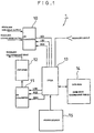
- an R/D converter 1 is substantially made up of an AD converter 10 to which sine-wave output and cosine-wave output of a resolver (not shown) are inputted, a DA converter 11 for outputting an excitation sine wave for the resolver, an amplifier 12 which is provided between the resolver and the DA converter 11 and amplifies an output signal from the DA converter 11, an FPGA 13 (Field Programmable Gate Array) which is provided between the AD converter 10 and the DA converter 11 and is an example of a gate array, and data ROM 14 connected to the FPGA 13 and storing sine-wave and cosine-wave tables for calculation of a rotor shaft angle.
- reference numeral 15 designates a power source connected to the FPGA 13 and supplying electric power to the R/D converter 1.
- the output (sine-wave output and cosine-wave output) of the resolver is inputted to the AD converter 10.
- the precision (resolution) of the AD converter 10 is provisionally made 16 bits.
- the FPGA 13 outputs input data (word clock LRC, bit clock BCK, serial data SDO) to the DA converter 11, and calculates the rotor shaft angle of the resolver on the basis of the output data of the AD converter 10 (AD conversion output of the sine-wave output and cosine-wave output).
- Fig. 2 shows operation timing of the AD converter 10.
- a fourth frequency of the word clock LRC becomes the sampling frequency.
- the AD conversion output SDI of the sine-wave output and cosine-wave output of the resolver in one period of the wordclock LRC is outputted in a serial format to a serial port of the FPGA 13, and serial data are taken in the serial port at the leading edge of the bit clock BCK.
- Fig. 3 shows timing when sine-wave data for excitation of the resolver are inputted to the DA converter 11.
- the sampling frequency is set 40 KHz, and the serial data SDO are inputted to the DA converter 11 so that a sine wave of 10KHz is obtained.
- the output of the DA converter 11 (sine wave for excitation of the resolver) is inputted to the amplifier 12 and is amplified so that a winding output voltage (sine-wave output and cosine-wave output) of the resolver comes to have a suitable value, and is supplied to the resolver as the sine wave for excitation.
- the sine-wave output and cosine-wave output of the resolver are taken in the FPGA 13.
- the AD converter 10 makes AD conversion of the sine-wave output and cosine-wave output of the resolver, and the AD conversion value is taken in the FPGA 13.
- sin ⁇ t of the equation (5) can be regarded as a constant, and the equation (5) becomes sin ( ⁇ - ⁇ ) .
- the sampling frequency set at 40 KHz becomes 10KHz.
- the sine-wave and cosine-wave table writes into the data ROM 14 values of 16 bits of sine and cosine to an angle [address of the data ROM 14 (address of the table)] obtained by dividing 360 ° angular space of the resolver into 4096 (12 bits) equal parts.
- the polarity of the AD conversion value of the sine-wave and cosine-wave output of the resolver is checked, so that the present position (present shaft angle) of the rotor of the resolver is judged.
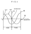
- the 360 ° angular space is divided into two parts, and the part of 0 - 180 ° is made PHASE 1, and the part of 180 - 360° is made PHASE 2. That is, as shown in Fig. 4, a quadrant 18 is set by a horizontal axis 16 along which an angle value becomes large from 0° to 360° toward the right from the left, and a vertical axis 17 (corresponding to an initial position of an address of a sine-wave table described later) indicating an angle value of 180 ° .
- the left (0 - 180 ° ) of the vertical axis 17 is made the PHASE 1
- the right (180 - 360 ° ) of the vertical axis 17 is made the PHASE 2.
- the angle ⁇ of the VCO is smaller than the rotor shaft angle ⁇ .
- the angle ⁇ of the VCO is larger than the rotor shaft angle ⁇ .
- the address of the VCO (sine-wave table) is made to increase or decrease (increment or decrement) by one LSB.
- the address of the VCO (sine-wave table) is made to increase or decrease as follows.
- the angle ⁇ of the VCO is equal to the rotor shaft angle ⁇ , so that the AD converter 10 outputs the address of the VCO (sine-wave table) to the serial port of the FPGA 13.
- the address of the VCO (sine-wave table) is made to increase or decrease as follows.
- the angle of the VCO is equal to the rotor shaft angle, so that the AD converter 10 outputs the address of the VCO (sine-wave table) to the serial port of the FPGA 13.
- the rotor shaft angle of the resolver is calculated by the gate array (FPGA 13) having logical operation capability.
- the gate array FPGA 13
- the rotor shaft angle calculation is performed by the gate array (FPGA 13) having logical operation capability.
- the tracking rate due to the PLL control is about 375 rps in the conventional tracking system R/D converter 1
- the tracking rate can be improved according to this embodiment, and for example, it can be made 610 rps.
- high speed response can be maintained.
- the AD converter 10 performs AD conversion of the sine-wave output and cosine-wave output of the resolver, so that the demodulator circuit 5 which has been required in the foregoing prior art becomes unnecessary.
- the response speed can be further improved by the omission of the operation of the demodulator circuit as compared with the prior art.
- the AD converter 10 When the sine wave for excitation of the resolver has the positive (or negative) maximum value, the AD converter 10 performs the AD conversion of the sine-wave output and cosine-wave output of the resolver, so that the sine wave for excitation can be regarded as a constant.
- the angle error can be made small.
- the FPGA 13 is provided between the AD converter 10 and the DA converter 11, makes calculation on the basis of digital values of the sine-wave output and cosine-wave output of the resolver inputted through the AD converter 10, and outputs an obtained digital value to the DA converter 11 and the like. Since the FPGA performs the digital operation of rotor shaft angle calculation, a compensation circuit of temperature drift which has been required in the prior art becomes unnecessary, and by this, the total structure becomes simple, and the cost can be made low. Besides, a comparatively inexpensive digital IC can be used for the FPGA 13, and by this, the cost of the whole apparatus can be further made low.
- the resolution of the rotor shaft angle is 12 bits, it is satisfactory if the precision of sin and cos values of the AD converter 10, and the sine-wave and cosine-wave table is 12 bits or more.
- the present invention has the following effects.
- the gate array calculates the rotor shaft angle of the resolver, and as compared with the prior art (resolver of the tracking system) for performing a kind of PLL control including the close loop made up of the demodulator circuit, the voltage controlled oscillator (VCO), and the like, it becomes possible to perform the rotor shaft angle calculation at higher speed, and the response speed can be improved by this.
- the prior art resolveer of the tracking system
- VCO voltage controlled oscillator
- the gate array obtains the rotor shaft angle by digital operation, so that a compensation circuit of temperature drift which has been required in the prior art becomes unnecessary, and by this, the total structure becomes simple, and the cost can be made low.
- a comparatively inexpensive digital IC can be used for the gate array, and by this, the cost of the whole apparatus can be further made low.
- such a structure can be made that at a specific phase time of the sine wave for excitation of the resolver, the sine-wave output signal and cosine-wave output signal of the resolver are subjected to AD conversion and are inputted to the gate array.
- the demodulator circuit which has been required in the prior art becomes unnecessary, and as compared with the prior art, the response speed can be further improved by the omission of the calculation of the demodulator circuit.
- the sine-wave output signal and cosine-wave output signal of the resolver are subjected to AD conversion, and the rotor shaft angle is calculated, so that the demodulator circuit which has been required in the prior art becomes unnecessary.
- the response speed can be further improved by the omission of the calculation of the demodulator circuit.
- the sine wave for excitation of the resolver has the positive (or negative) maximum value
- the sine-wave output and cosine-wave output of the resolver are subjected to AD conversion, and the sine wave for excitation can be regarded as a constant.
- the angle of the VCO is made to correspond to the rotor shaft angle and it becomes possible to recognize the size relation between both.
- the fifth aspect of the invention it becomes possible to increase or decrease the address of the VCO (sine-wave table) by each bit according to the size relation between the angle of the VCO and the angle of the rotor shaft, and by this, position setting (position judgement) with high precision can be made.
- the address value of the VCO (sine-wave table) is made to increment, so that the precision of position setting (position judgement) can be improved.
- the address value of the VCO (sine-wave table) is made to decrement, so that the precision of position setting (position judgement) can be improved.
- the AD conversion value of the sine-wave output of the resolver and the sine value of the angle of the VCO are compared with each other, the address of the VCO (sine-wave table) is increased or decreased by one bit according to a quadrant of the rotor shaft angle, and an angle corresponding to the address of the VCO (sine-wave table) is made to approach the value corresponding to the rotor shaft angle. Accordingly, the precision of position setting (position judgement) can be improved.
Landscapes
- Engineering & Computer Science (AREA)
- Theoretical Computer Science (AREA)
- Transmission And Conversion Of Sensor Element Output (AREA)
- Measurement Of Length, Angles, Or The Like Using Electric Or Magnetic Means (AREA)
Abstract
Description
Claims (8)
- An R/D converter, comprising:a gate array to which data obtained through AD conversion of sine-wave output and cosine-wave output of a resolver are inputted and has logical operation capability,
wherein the gate array obtains a rotor shaft angle of the resolver by digital operation on the basis of the digital input data. - An R/D converter according to claim 1, wherein the gate array inputs digital data for an excitation sine wave of resolver to a DA converter, and the DA converter obtains the excitation sine wave of the resolver on the basis of the input data from the gate array.
- An R/D converter according to claim 2, wherein at a specific phase time of the excitation sine wave of the resolver, a sine-wave output signal and a cosine-wave output signal of the resolver are subjected to AD conversion, and the rotor shaft angle is calculated.
- An R/D converter according to any one of claims 1 to 3, wherein a quadrant formed by dividing an angular space of the resolver into two equal parts is obtained, the rotor shaft angle of the resolver in the quadrant is obtained on the basis of polarities of the sine-wave output and the cosine-wave output of the resolver, and an initial angle of a rotor shaft angle for calculating VCO is set at a center of the divided quadrant.
- An R/D converter according to claim 4, wherein a sine value corresponding to a difference between the rotor shaft angle of the resolver and an angle corresponding to an address of a sine-wave table is calculated, and an angle of the VCO is increased or decreased on the basis of size relation between the rotor shaft angle of the resolver and the angle of the VCO.
- An R/D converter according to claim 5, wherein the quadrant is set such that a value in the angular space becomes large from the left to the right, and in the quadrant, if the rotor shaft angle of the resolver exists right as compared with the angle of the VCO, the angle of the VCO is made to increment.
- An R/D converter according to claim 5, wherein the quadrant is set such that a value in the angular space becomes large from the left to the right, and in the quadrant, if the rotor shaft angle of the resolver exists left as compared with the angle of the VCO, the angle of the VCO is made to decrement.
- An R/D converter according to any one of claims 5 to 7, wherein an AD conversion value of the sine-wave output of the resolver and a sine value of the angle of the VCO are compared with each other, an address corresponding to an angle of the sine-wave table is increased or decreased by one bit according to the rotor shaft angle in the quadrant, and an angle corresponding to the address is made to approach the rotor shaft angle.
Applications Claiming Priority (2)
| Application Number | Priority Date | Filing Date | Title |
|---|---|---|---|
| JP15098699 | 1999-05-31 | ||
| JP11150986A JP2000337924A (en) | 1999-05-31 | 1999-05-31 | R/d converter |
Publications (2)
| Publication Number | Publication Date |
|---|---|
| EP1058389A2 true EP1058389A2 (en) | 2000-12-06 |
| EP1058389A3 EP1058389A3 (en) | 2003-07-09 |
Family
ID=15508796
Family Applications (1)
| Application Number | Title | Priority Date | Filing Date |
|---|---|---|---|
| EP00100395A Ceased EP1058389A3 (en) | 1999-05-31 | 2000-01-08 | R/D converter |
Country Status (3)
| Country | Link |
|---|---|
| US (1) | US6320524B1 (en) |
| EP (1) | EP1058389A3 (en) |
| JP (1) | JP2000337924A (en) |
Cited By (3)
| Publication number | Priority date | Publication date | Assignee | Title |
|---|---|---|---|---|
| WO2006101687A3 (en) * | 2005-03-18 | 2007-10-18 | Honeywell Int Inc | Solid-state synchro/resolver converter |
| CN102435133A (en) * | 2011-09-02 | 2012-05-02 | 北京邮电大学 | Rotary transformer angle measurement system based on FPGA |
| CN108646617A (en) * | 2018-04-26 | 2018-10-12 | 浙江大学 | A kind of absolute encoder angle reading circuit and method based on FPGA |
Families Citing this family (8)
| Publication number | Priority date | Publication date | Assignee | Title |
|---|---|---|---|---|
| US7205916B1 (en) * | 2006-01-27 | 2007-04-17 | Alliant Techsystems Inc. | Digital method and apparatus for resolving shaft position |
| US7248994B1 (en) | 2006-01-27 | 2007-07-24 | Alliant Techsystems Inc. | Digital method and apparatus for sensing position with a linear variable differential transformer |
| DE102006022993A1 (en) * | 2006-05-17 | 2007-11-22 | Robert Bosch Gmbh | Method for providing a correlation |
| US7268710B1 (en) * | 2006-07-11 | 2007-09-11 | Hiwin Mikrosystems Corp. | Logic device for the transformation of the output of the RDC into series A-B pulses |
| CN102203545B (en) * | 2008-12-30 | 2014-12-03 | 配天(安徽)电子技术有限公司 | Hall resolver and Hall rotary encoder made of it |
| US9059732B2 (en) * | 2013-03-21 | 2015-06-16 | Hamilton Sundstrand Corporation | Resolver-to-digital converter |
| CN116232335A (en) * | 2022-12-09 | 2023-06-06 | 连云港杰瑞电子有限公司 | Shaft Angle-to-Digital Conversion Method of Single Chip Digital Type Ⅱ Tracking Loop |
| CN119602801B (en) * | 2024-11-15 | 2026-03-20 | 中国电子科技集团公司第四十三研究所 | A fixed-amplitude digital-to-axis-angle converter and its working method |
Family Cites Families (13)
| Publication number | Priority date | Publication date | Assignee | Title |
|---|---|---|---|---|
| US4021714A (en) * | 1975-01-08 | 1977-05-03 | Contraves-Goerz Corporation | Servo system employing a tracking digital angle encoder |
| US4486845A (en) * | 1982-07-23 | 1984-12-04 | The Singer Company | Resolver to incremental shaft encoder converter |
| US4933674A (en) * | 1984-06-11 | 1990-06-12 | Allen-Bradley Company, Inc. | Method and apparatus for correcting resolver errors |
| JPS62171229A (en) * | 1986-01-23 | 1987-07-28 | Mitsubishi Electric Corp | Digital operation type synchro/digital converter |
| US4857926A (en) * | 1987-08-25 | 1989-08-15 | Honeywell Inc. | Phase-responsive angular tracking device |
| US4989001A (en) * | 1989-04-20 | 1991-01-29 | Advanced Micro Controls, Inc. | Microcontroller based resolver-to-digital converter |
| JPH03261820A (en) * | 1990-03-12 | 1991-11-21 | Tamagawa Seiki Co Ltd | Digital R/D converter |
| US5455498A (en) * | 1990-05-09 | 1995-10-03 | Omron Corporation | Angle of rotation detector |
| JPH04183021A (en) * | 1990-11-16 | 1992-06-30 | Mitsubishi Electric Corp | Analog/digital converter |
| US5162798A (en) * | 1991-06-17 | 1992-11-10 | Pacific Scientific Company | Resolver to digital converter |
| US5646496A (en) * | 1994-11-08 | 1997-07-08 | Dana Corporation | Apparatus and method for generating digital position signals for a rotatable shaft |
| MY120887A (en) * | 1995-06-08 | 2005-12-30 | Sony Corp | Rotation position detecting device and motor device. |
| JPH1198876A (en) * | 1997-09-22 | 1999-04-09 | Hitachi Ltd | Position / speed detector |
-
1999
- 1999-05-31 JP JP11150986A patent/JP2000337924A/en active Pending
- 1999-12-23 US US09/471,390 patent/US6320524B1/en not_active Expired - Fee Related
-
2000
- 2000-01-08 EP EP00100395A patent/EP1058389A3/en not_active Ceased
Cited By (3)
| Publication number | Priority date | Publication date | Assignee | Title |
|---|---|---|---|---|
| WO2006101687A3 (en) * | 2005-03-18 | 2007-10-18 | Honeywell Int Inc | Solid-state synchro/resolver converter |
| CN102435133A (en) * | 2011-09-02 | 2012-05-02 | 北京邮电大学 | Rotary transformer angle measurement system based on FPGA |
| CN108646617A (en) * | 2018-04-26 | 2018-10-12 | 浙江大学 | A kind of absolute encoder angle reading circuit and method based on FPGA |
Also Published As
| Publication number | Publication date |
|---|---|
| JP2000337924A (en) | 2000-12-08 |
| EP1058389A3 (en) | 2003-07-09 |
| US6320524B1 (en) | 2001-11-20 |
Similar Documents
| Publication | Publication Date | Title |
|---|---|---|
| EP0704048B1 (en) | Dither signal remover for dithered ring laser gyro | |
| EP0772025B1 (en) | Device and method for phase detection, for use in a position detection system | |
| US7088025B2 (en) | Variable-reluctance resolver and rotational angle sensor using same | |
| US7015840B2 (en) | Resolver/digital converter | |
| EP0308656B1 (en) | Method and apparatus for generating a digital signal indicative on an angular displacement | |
| US4270077A (en) | Demodulatorless synchro position sensor apparatus utilizing square wave excitation | |
| US6320524B1 (en) | R/D converter | |
| CN105547335B (en) | A kind of signal processing system of magnetoresistance transformer | |
| EP2038615A2 (en) | Methods and apparatus for an analog rotational sensor | |
| EP1850137A2 (en) | Rotational position measuring device | |
| EP1058390B1 (en) | R/D converter | |
| JP4923730B2 (en) | Compensation method and angle detection apparatus using the same in resolver angle detection | |
| JPWO2020152762A1 (en) | A rotation angle detection device and an electric power steering device including the rotation angle detection device. | |
| JPH1137794A (en) | Direct resolver for digital converter | |
| CN205384031U (en) | Vernier resolver's peaking circuit | |
| US8924179B2 (en) | Assembly and method for determining an angular position | |
| Karabeyli et al. | Enhancing the accuracy for the open-loop resolver to digital converters | |
| CN118548923A (en) | Method and device for calculating differential phase shift of rotary transformer, circuit and electronic equipment | |
| CN205317219U (en) | Vernier resolver's signal processing device | |
| JPH0230726Y2 (en) | ||
| CN115667843A (en) | Compensation for temperature-dependent, quadrature-induced zero-rate offsets for MEMS gyroscopes | |
| JPS62144021A (en) | Resolver detection device | |
| JPH0342516A (en) | Resolver signal transmission equipment | |
| KR100189937B1 (en) | Apparatus and method for estimating rotation angle using sinusoidal signal | |
| JP2938472B2 (en) | Rotation angle detector |
Legal Events
| Date | Code | Title | Description |
|---|---|---|---|
| PUAI | Public reference made under article 153(3) epc to a published international application that has entered the european phase |
Free format text: ORIGINAL CODE: 0009012 |
|
| AK | Designated contracting states |
Kind code of ref document: A2 Designated state(s): AT BE CH CY DE DK ES FI FR GB GR IE IT LI LU MC NL PT SE |
|
| AX | Request for extension of the european patent |
Free format text: AL;LT;LV;MK;RO;SI |
|
| PUAL | Search report despatched |
Free format text: ORIGINAL CODE: 0009013 |
|
| AK | Designated contracting states |
Designated state(s): AT BE CH CY DE DK ES FI FR GB GR IE IT LI LU MC NL PT SE |
|
| AX | Request for extension of the european patent |
Extension state: AL LT LV MK RO SI |
|
| 17P | Request for examination filed |
Effective date: 20031227 |
|
| AKX | Designation fees paid |
Designated state(s): AT BE CH CY DE DK ES FI FR GB GR IE IT LI LU MC NL PT SE |
|
| 17Q | First examination report despatched |
Effective date: 20040226 |
|
| STAA | Information on the status of an ep patent application or granted ep patent |
Free format text: STATUS: THE APPLICATION HAS BEEN REFUSED |
|
| 18R | Application refused |
Effective date: 20050522 |