EP1058346A2 - Kabelzugentlastungshalter - Google Patents
Kabelzugentlastungshalter Download PDFInfo
- Publication number
- EP1058346A2 EP1058346A2 EP00112014A EP00112014A EP1058346A2 EP 1058346 A2 EP1058346 A2 EP 1058346A2 EP 00112014 A EP00112014 A EP 00112014A EP 00112014 A EP00112014 A EP 00112014A EP 1058346 A2 EP1058346 A2 EP 1058346A2
- Authority
- EP
- European Patent Office
- Prior art keywords
- section
- strain relief
- bracket
- cable
- wall
- Prior art date
- Legal status (The legal status is an assumption and is not a legal conclusion. Google has not performed a legal analysis and makes no representation as to the accuracy of the status listed.)
- Withdrawn
Links
Images

Classifications
-
- H—ELECTRICITY
- H01—ELECTRIC ELEMENTS
- H01R—ELECTRICALLY-CONDUCTIVE CONNECTIONS; STRUCTURAL ASSOCIATIONS OF A PLURALITY OF MUTUALLY-INSULATED ELECTRICAL CONNECTING ELEMENTS; COUPLING DEVICES; CURRENT COLLECTORS
- H01R9/00—Structural associations of a plurality of mutually-insulated electrical connecting elements, e.g. terminal strips or terminal blocks; Terminals or binding posts mounted upon a base or in a case; Bases therefor
- H01R9/22—Bases, e.g. strip, block, panel
- H01R9/24—Terminal blocks
- H01R9/2416—Means for guiding or retaining wires or cables connected to terminal blocks
-
- H—ELECTRICITY
- H02—GENERATION; CONVERSION OR DISTRIBUTION OF ELECTRIC POWER
- H02G—INSTALLATION OF ELECTRIC CABLES OR LINES, OR OF COMBINED OPTICAL AND ELECTRIC CABLES OR LINES
- H02G3/00—Installations of electric cables or lines or protective tubing therefor in or on buildings, equivalent structures or vehicles
- H02G3/26—Installations of cables, lines, or separate protective tubing therefor directly on or in walls, ceilings, or floors
-
- H—ELECTRICITY
- H01—ELECTRIC ELEMENTS
- H01R—ELECTRICALLY-CONDUCTIVE CONNECTIONS; STRUCTURAL ASSOCIATIONS OF A PLURALITY OF MUTUALLY-INSULATED ELECTRICAL CONNECTING ELEMENTS; COUPLING DEVICES; CURRENT COLLECTORS
- H01R13/00—Details of coupling devices of the kinds covered by groups H01R12/70 or H01R24/00 - H01R33/00
- H01R13/58—Means for relieving strain on wire connection, e.g. cord grip, for avoiding loosening of connections between wires and terminals within a coupling device terminating a cable
- H01R13/5804—Means for relieving strain on wire connection, e.g. cord grip, for avoiding loosening of connections between wires and terminals within a coupling device terminating a cable comprising a separate cable clamping part
- H01R13/5812—Means for relieving strain on wire connection, e.g. cord grip, for avoiding loosening of connections between wires and terminals within a coupling device terminating a cable comprising a separate cable clamping part the cable clamping being achieved by mounting the separate part on the housing of the coupling device
Definitions
- the invention relates generally to cable strain relief brackets. More particularly, the present invention relates to cable strain relief brackets for use with conventional and modular furniture walls.
- Cubicles may be arbitrarily set up and removed depending on the needs of the office.
- the modular furniture walls that comprise boundaries of the cubicle typically have port openings that allow for connection for items utilizing copper wire and/or optical fibers. These port openings receive cables that extend between the walls of the panels.
- a connector mounts over each port opening allowing for connection with the cables.
- optical fiber cable in offices further compounds the strain problem in conventional and modular furniture systems.
- the sensitivity of optical fibers to excessive bending parlays the importance of a strain relief device in environments that may subject the cables to increased stresses.
- Optical fiber cables are particularly sensitive to bending due to the possibility of micro-breaks or complete breaks in the fiber, thereby degrading or disrupting the signal. Cables must not violate a critical bending radius to prevent such damage to the fibers.
- the present invention introduces a new apparatus and method for installing a strain relief device in conventional and modular furniture walls.
- the strain relief apparatus of the present invention comprises a bracket adapted to fit inside conventional and modular furniture walls adjacent to the opening where the cable and cable connections are located.
- the bracket adheres to the inside of the furniture wall and clamps to the opening to prevent movement between the cables and furniture wall or a wall plate that houses connectors or jacks. Cables extending inside the furniture wall to the opening are secured to the strain relief bracket via tie or cable wraps.
- the strain relief bracket is elongated with a low profile to maintain minimum bend radius from the point of cable sheath retention to the point of termination. Round and U-shaped holes are equally spaced on the offset of the strain relief bracket for securing the tie wraps to the strain relief bracket.
- the strain relief bracket preferably has three sections.
- the first section nearest the opening has an end flange adapted to be attached to the edge of a wall opening.
- the flange of the bracket may then be crimped and secured to the edge by using pliers or other such tools that perform the same function.
- One side of the first section is securable to the inside of the furniture wall.
- the bracket may be attached by using double-sided tape, but may also include hook-and-loop such as VelcroTM, glue, or any other adhesion means readily apparent in the art, including as a nut-and-bolt connection.
- the adhesion of the device to the furniture wall increases the shear force required to break loose the assembly when the cables are pulled from any direction, thereby relieving the strain on the connectors at the end of the cables.
- the second or offset section of the strain relief bracket is preferably in a second plane relative to the first section and spaced away from the inside of the wall when the strain relief is attached to the wall.
- the first and second planes may or may not be parallel to one another.
- Round and U-shaped holes are spaced on the offset section for receiving the tie wraps, cable wraps, or other fasteners.
- the cables extend from an opening in the wall and transverse to the first section.
- the cables are secured by tie wraps or other fasteners to the holes, such that strain is directed away from the connectors and adapters.
- the second section of the bracket also secures the cables a constant distance from the port opening, thereby preventing bending of the cables at or near the connectors in the opening.
- the second section may also serve the function of separating groups of cables and preventing entanglement when the terminating ends of the cables are moved relative to the port opening.
- the third or transition section extends between the first and offset section at a slope away from the first section and inner wall of the furniture.
- This slope provides an area between the wall and the strain relief device for the tie wraps or other fasteners to be used without having to remove the device from the wall, once installed.
- the angle of the slope of the transition section is not critical to the function of the offset section.
- the slope of the transition section may be abrupt, such as 90°, causing the bracket to have more of a Z-shape, or the transition section may have a gradual slope, providing more of an S-shape.
- the function of the transition section will be served as long as the first section and offset section are maintained a constant distance from the cable connectors or adapters.
- a wall plate is removed from the furniture wall panel, or, if appropriate, a hole is made in the wall.
- the length of excess cable to reach from the tie wraps at the second (offset) section to a termination point at the connector or wall plate is determined.
- the end of the cable is then connectorized for connection with the connector plate.
- the cable is next secured to the offset section of the strain relief bracket by tie wraps or cable wraps. Double-sided tape or other such adhesion means as hook-and-loop or glue is applied to the inside of the strain relief bracket.
- the strain relief bracket is then hooked around the edge of the port opening and pressed against the inside of the furniture wall panel for securement thereto.
- the end of the first section of the strain relief bracket is then clamped around the edge of the port opening using pliers or other such clamping devices.
- the connectorized cable is connected to the connector plate and finally plugged into the wall.
- This invention although disclosed for conventional and modular furniture wall arrangements, may be used with other applications that have apertures for receiving cables from an external source and require strain relief for such cables and connectors.
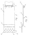
- Figure 1 is a cross-section of wall 1 , which may be either a conventional, stationary wall or a modular furniture wall, having two panels 2 (with a conventional wall, the panels would be gypsum board) spaced apart, allowing cables 3 to pass therebetween. Cables 3 may be either optical fibers, fiber optic cables, or copper cables.
- the wall 1 has an opening 7 on front side 5 to allow for access to cables 3 , etc. The opening 7 may already be in the wall and covered with a flat wall plate (not shown) or the opening 7 may have to be cut into one of the panels 2 . The ends of cables 3 need to then be able to connect with other cables or equipment at or near the opening 7 .
- This connection usually requires connectors 15 or a connector sleeve that is mounted in connector plate 11 , which usually covers opening 7 .
- Strain relief bracket 17 is attached to cables 3 at one end and to the wall 1 at its other end to prevent the cables 3 from pulling directly on the connector 15 or the connector plate 11 and causing stress or a bend in the cables 3 if a force is applied to the cables 3 .
- strain relief bracket 17 preferably has three sections: a first section 19 , a transitional section 21 , and an offset section 23 .
- First section 19 is preferably considerably longer than offset section 23 .
- the three sections may be of any length relative to one another, so long as there is sufficient distance between the ends to prevent the bend radius from being violated.
- First section 19 also has an end flange 25 adapted to be hooked around edge 27 of wall opening 7 .
- the end flange 25 may have a larger radius than that shown in the figures if the strain relief bracket 17 is to be used with a conventional wall. End flange 25 of strain relief bracket 17 may be crimped and secured to edge 27 of wall opening 7 by pliers or other such tools, not shown.
- End flange 25 is at an acute angle 26 relative to first section 19, as shown in Figure 3, but may be at any angle relative to the first section 19 as long as a constant distance is maintained from cables 3 to the connector 15 .
- First section 19 has adhesive side 29 for adherence to inside surface 31 of furniture wall 1.
- adhesive side 29 comprises double-sided tape 32 , or it may comprise a layer of glue or hook and loop material.
- the end flange 25 has width W that fits between the tabs 12 on the connector plate 11 , and shoulders 13 extend beyond the tabs 12 and the edges of the plate 11 . Such an arrangement prevents the strain relief bracket 17 and the end flange 25 from being pushed into the connector plate 11 and putting strain on the connector 15 or breaking the connection if the strain relief bracket 17 is dislodged from the wall toward the connector plate 11 .
- Offset section 23 of strain relief bracket 17 is spaced away from first section 19 in a second plane relative to first section 19 .
- Offset section 23 has holes 37 , which are spaced on offset section 23, to secure cables 3 to strain relief bracket 17.
- Offset section 23 also has spaced U-shaped openings 33 that are located at the terminal end 35 of offset section 23. The U-shaped openings 33 aid in securing the cables 3 to the strain relief bracket 17 once the bracket is installed within wall 1 . Once installed in the wall, access to the underside of the bracket 17 is limited, making it difficult, if not impossible, to route the tie wrap 39 back through another hole from the underside of the bracket 17 .
- a user can insert a tie wrap 39 through one of the holes 37, and route it around the end 35 to secure the cables 3 , eliminating the need to access the underside of the bracket 17 .
- the user need not try to get the tie wrap 39 back through one of the holes 37 , but route it through the U-shaped openings 33 .
- the configuration of the U-shaped openings prevent the tie wrap from moving along the end of the bracket 17 .
- Transition section 21 preferably extends between first section 19 and offset section 23 at an angle 22 (Figure 3) of approximately 150° away from first section 19 (and front side 5 of furniture wall 1 when attached). Transition section 21 preferably maintains first section 19 and offset section 23 in parallel planar relationship. However, first section 19 and offset section 23 need not be parallel, however, the angle of offset section 23 must be such that terminal end 35 does not become a sharp edge that can cause undesirable bending in the cables 3 at that end. While the pictured embodiment illustrates that the boundaries between each of the sections of strain relief bracket appear to define discreet sections, the boundaries could be more gradual. For example, the strain relief bracket 17 could appear more like the letter S than the letter Z, as illustrated.
- the wall plate is removed from front side 5 of wall 1 or a hole is cut in the wall 1 .
- Cables 3 are then fed inside the furniture wall 1 , if not already present.
- the flange 25 of the strain relief bracket 17 is then attached to the edge 27 of the wall opening 7 and the first section 19 of bracket 17 is adhered to the inside surface 31 of the wall 1 .
- Cables 3 are then secured to offset section 23 of strain relief bracket 17 by tie wraps 39.
- the cables 3 are then connectorized with connectors 15 for engagement with connector plate 11 .
- the connector plate 11 is then inserted into the opening 7 .
- the cables 3 in the wall 1 could first be secured to offset section 23 of strain relief bracket 17 by tie wraps 39.
- the cables 3 will be secured at point that allows for a length of cable that is slightly longer than the distance from where they are secured to the connector 15. This allows for some "play" in the cable to prevent imparting strain on the connectors.
- Bracket 17 is then hooked to edge 27 of wall opening 7 and adhered to inside surface 31 of wall 1 .
- the cables 3 are then connectorized.
- Connector 15 is secured in a sleeve in connector plate 11 (or the sleeve may be integral with the plate), which in turn snaps into wall opening 7 , thereby providing external access for connection with cable 3 .
- the bi-planar relationship of bracket 17 prevents bending of cables 3 extending from connector or adapter 15 and also protects connector 15 .
- Bracket 17 may have varying sizes of end flange 25 relative to body of bracket 17 .
- the size of the bracket 17 and end flange 25 will change depending on the application.
- An alternative embodiment of the present invention comprises a reduction in the overall width of strain relief bracket to a matching width of clamping flange of the connector plate 11 .
Landscapes
- Engineering & Computer Science (AREA)
- Architecture (AREA)
- Civil Engineering (AREA)
- Structural Engineering (AREA)
- Installation Of Indoor Wiring (AREA)
Applications Claiming Priority (2)
| Application Number | Priority Date | Filing Date | Title |
|---|---|---|---|
| US09/326,352 US6262373B1 (en) | 1999-06-04 | 1999-06-04 | Cable strain relief bracket |
| US326352 | 1999-06-04 |
Publications (2)
| Publication Number | Publication Date |
|---|---|
| EP1058346A2 true EP1058346A2 (de) | 2000-12-06 |
| EP1058346A3 EP1058346A3 (de) | 2001-07-04 |
Family
ID=23271849
Family Applications (1)
| Application Number | Title | Priority Date | Filing Date |
|---|---|---|---|
| EP00112014A Withdrawn EP1058346A3 (de) | 1999-06-04 | 2000-06-02 | Kabelzugentlastungshalter |
Country Status (2)
| Country | Link |
|---|---|
| US (1) | US6262373B1 (de) |
| EP (1) | EP1058346A3 (de) |
Families Citing this family (6)
| Publication number | Priority date | Publication date | Assignee | Title |
|---|---|---|---|---|
| FR2785340B1 (fr) * | 1998-11-03 | 2001-01-26 | Metal Deploye Sa | Dispositif de fixation d'un fil sur un element porteur muni d'au moins une ouverture et ensemble porteur pour chemin de cables comportant au moins un tel dispositif |
| DE20304498U1 (de) * | 2003-03-20 | 2004-07-29 | Arturo Salice S.P.A., Novedrate | Adapter für eine Bremsverzögerungsvorrichtung |
| US20090059552A1 (en) * | 2007-08-30 | 2009-03-05 | Wade Womack | Cable spool for use with glanded fiber trucks |
| US8839579B2 (en) * | 2009-04-25 | 2014-09-23 | Everett L. Lakoduk | Remodeling cable protecting plate |
| US8622481B2 (en) | 2011-01-25 | 2014-01-07 | Joy Mm Delaware, Inc. | Fiber optic cable protection in a mining system |
| US20140041898A1 (en) * | 2012-08-13 | 2014-02-13 | Ho Cheung | Article for securing and ordering cables leading away from a key switch |
Family Cites Families (8)
| Publication number | Priority date | Publication date | Assignee | Title |
|---|---|---|---|---|
| US2273487A (en) * | 1940-11-16 | 1942-02-17 | Horace W Heyman | Strain-relief means for electrical cords |
| US2466504A (en) * | 1947-04-05 | 1949-04-05 | Elwood D Stoyer | Holding device for electric cables |
| US3197615A (en) * | 1961-03-20 | 1965-07-27 | Wiegand Co Edwin L | Electric heating apparatus |
| US5821458A (en) * | 1997-03-25 | 1998-10-13 | Orcon Corporation | Substantially rigid strain relief bracket for electrical appliances |
| US5918837A (en) * | 1997-10-17 | 1999-07-06 | Alcatel Usa Sourcing, L.P. | Cable retainer bracket and method of installation |
| US6080010A (en) * | 1998-03-16 | 2000-06-27 | Lucent Technologies Inc. | Bracket design for a back to back individual strain relief of two modular connectors |
| US6073890A (en) * | 1998-03-19 | 2000-06-13 | Lucent Technologies Inc. | Strain relief mechanism and method |
| US6013875A (en) * | 1998-08-04 | 2000-01-11 | Fridenberg; Stephen J. | Transitional sleeving for coaxial cable |
-
1999
- 1999-06-04 US US09/326,352 patent/US6262373B1/en not_active Expired - Fee Related
-
2000
- 2000-06-02 EP EP00112014A patent/EP1058346A3/de not_active Withdrawn
Also Published As
| Publication number | Publication date |
|---|---|
| US6262373B1 (en) | 2001-07-17 |
| EP1058346A3 (de) | 2001-07-04 |
Similar Documents
| Publication | Publication Date | Title |
|---|---|---|
| US4976510A (en) | Communication outlet | |
| US6940017B2 (en) | Breakaway member | |
| US6170784B1 (en) | Cable management device | |
| EP0871909B1 (de) | Spleissgehäuse für ein faseroptisches kabel | |
| US7459633B2 (en) | Wire management system | |
| US20030222185A1 (en) | Apparatus and method for anchoring a cable | |
| CA2194928A1 (en) | Anchor for receiving cable bundling straps | |
| JP2002295421A (ja) | ワイヤ及びケーブルを整理するシステム | |
| WO1998041891A1 (en) | Fiber optic cable bend radius controller | |
| US6300567B1 (en) | Junction box for low voltage data, video or communications connections | |
| WO2002085039A3 (en) | Cable management bracket for a telecommunications rack | |
| AU2002242836B2 (en) | Cable termination device | |
| US7588216B1 (en) | Fiber optic cabling management using hook and loop fabric | |
| US6262373B1 (en) | Cable strain relief bracket | |
| AU2002242836A1 (en) | Cable termination device | |
| CN114868058B (zh) | 具有分支/适配器模块的终端系统组件 | |
| US20030087550A1 (en) | Simplified interconnect for center of wide body aircraft | |
| US5527990A (en) | Mounting apparatus for an electrical power distribution device | |
| US20060207793A1 (en) | Device plate for mounting a communications device to a raceway | |
| US20100316345A1 (en) | Fiber optic panel and method | |
| US20060169482A1 (en) | Adhesive backed mount strip | |
| HK1044992B (zh) | 一種彈性夾 | |
| JPS6313398A (ja) | ケ−ブル用クランプ装置 | |
| EP1680846B1 (de) | Widerhakenhalterung | |
| WO2013122904A1 (en) | Wall stud mounting bracket for securing and positioning flexible conduit and cable |
Legal Events
| Date | Code | Title | Description |
|---|---|---|---|
| PUAI | Public reference made under article 153(3) epc to a published international application that has entered the european phase |
Free format text: ORIGINAL CODE: 0009012 |
|
| AK | Designated contracting states |
Kind code of ref document: A2 Designated state(s): AT BE CH CY DE DK ES FI FR GB GR IE IT LI LU MC NL PT SE |
|
| AX | Request for extension of the european patent |
Free format text: AL;LT;LV;MK;RO;SI |
|
| RIN1 | Information on inventor provided before grant (corrected) |
Inventor name: HARVEY, JOHN DAVID Inventor name: BULLER, BILLY E., JR. Inventor name: DAGLEY, MARK R. |
|
| PUAL | Search report despatched |
Free format text: ORIGINAL CODE: 0009013 |
|
| AK | Designated contracting states |
Kind code of ref document: A3 Designated state(s): AT BE CH CY DE DK ES FI FR GB GR IE IT LI LU MC NL PT SE |
|
| AX | Request for extension of the european patent |
Free format text: AL;LT;LV;MK;RO;SI |
|
| RIC1 | Information provided on ipc code assigned before grant |
Free format text: 7H 02G 3/38 A, 7H 01R 9/24 B |
|
| AKX | Designation fees paid | ||
| REG | Reference to a national code |
Ref country code: DE Ref legal event code: 8566 |
|
| STAA | Information on the status of an ep patent application or granted ep patent |
Free format text: STATUS: THE APPLICATION IS DEEMED TO BE WITHDRAWN |
|
| 18D | Application deemed to be withdrawn |
Effective date: 20020105 |