EP1057739A2 - Behälterkappe mit das Abrutschen verhindernden Flansch - Google Patents
Behälterkappe mit das Abrutschen verhindernden Flansch Download PDFInfo
- Publication number
- EP1057739A2 EP1057739A2 EP00108531A EP00108531A EP1057739A2 EP 1057739 A2 EP1057739 A2 EP 1057739A2 EP 00108531 A EP00108531 A EP 00108531A EP 00108531 A EP00108531 A EP 00108531A EP 1057739 A2 EP1057739 A2 EP 1057739A2
- Authority
- EP
- European Patent Office
- Prior art keywords
- cap
- flange
- container
- side wall
- user
- Prior art date
- Legal status (The legal status is an assumption and is not a legal conclusion. Google has not performed a legal analysis and makes no representation as to the accuracy of the status listed.)
- Withdrawn
Links
Images

Classifications
-
- B—PERFORMING OPERATIONS; TRANSPORTING
- B65—CONVEYING; PACKING; STORING; HANDLING THIN OR FILAMENTARY MATERIAL
- B65D—CONTAINERS FOR STORAGE OR TRANSPORT OF ARTICLES OR MATERIALS, e.g. BAGS, BARRELS, BOTTLES, BOXES, CANS, CARTONS, CRATES, DRUMS, JARS, TANKS, HOPPERS, FORWARDING CONTAINERS; ACCESSORIES, CLOSURES, OR FITTINGS THEREFOR; PACKAGING ELEMENTS; PACKAGES
- B65D23/00—Details of bottles or jars not otherwise provided for
- B65D23/10—Handles
- B65D23/102—Gripping means formed in the walls, e.g. roughening, cavities, projections
-
- B—PERFORMING OPERATIONS; TRANSPORTING
- B05—SPRAYING OR ATOMISING IN GENERAL; APPLYING FLUENT MATERIALS TO SURFACES, IN GENERAL
- B05B—SPRAYING APPARATUS; ATOMISING APPARATUS; NOZZLES
- B05B11/00—Single-unit hand-held apparatus in which flow of contents is produced by the muscular force of the operator at the moment of use
- B05B11/01—Single-unit hand-held apparatus in which flow of contents is produced by the muscular force of the operator at the moment of use characterised by the means producing the flow
- B05B11/10—Pump arrangements for transferring the contents from the container to a pump chamber by a sucking effect and forcing the contents out through the dispensing nozzle
- B05B11/1042—Components or details
- B05B11/1052—Actuation means
-
- B—PERFORMING OPERATIONS; TRANSPORTING
- B65—CONVEYING; PACKING; STORING; HANDLING THIN OR FILAMENTARY MATERIAL
- B65D—CONTAINERS FOR STORAGE OR TRANSPORT OF ARTICLES OR MATERIALS, e.g. BAGS, BARRELS, BOTTLES, BOXES, CANS, CARTONS, CRATES, DRUMS, JARS, TANKS, HOPPERS, FORWARDING CONTAINERS; ACCESSORIES, CLOSURES, OR FITTINGS THEREFOR; PACKAGING ELEMENTS; PACKAGES
- B65D47/00—Closures with filling and discharging, or with discharging, devices
Definitions
- the present invention relates to the field of containers and more particularly, relates to a container cap.
- the type of spray used may generally be characterized as those formed by means of a pump arranged on the container closure and which is activated by pressure of the finger or thumb of the user or the so called spray can which generally utilizes a propellant gas.
- a propellant gas is in disfavor for many different reasons including environmental considerations.
- certain propellant gases have been shown to be carcinogenic while others, such as medicinal sprays, do not readily lend themselves to use of a propellant gas.
- the pump sprays have been known for a number of years and many different types are used in the art. Basically, they provide an atomization of the fluid and provide a superior product usage compared to the propellant gas sprays. However, such pumps are dependent upon the pressure delivered by the finger or thumb of the user. One problem which occurs with such pump sprays is the container may become contaminated on the exterior surface with the spray which can then cause slippage and accordingly, a lower pressure is applied on the pump and the atomization is therefore insufficient.
- a cap for use with a pump spray container, the cap comprising a body having an internal passageway to receive a spray mechanism, a side wall surrounding the passageway, a flange extending outwardly from an exterior surface of the side wall, the flange extending outwardly for a distance sufficient to act as an abutting member for a finger of a hand of a user.
- a method of positioning the index finger of a user on a spray container having a plunger comprising the step of supplying a container having a cap, the cap comprising a body including a side wall, a flange extending outwardly from an exterior surface of the side wall, the flange extending outwardly for a distance sufficient to act as an abutting member for a finger of a hand of a user and the flange being spaced from the plunger by a distance sufficient to correctly position the index finger.
- the cap of the present invention may be utilized with any suitable spray head.
- it may be utilized with propellant based spray heads as well as the pump action type of spray head although the maximum benefit will be gained from the pump action as the propellant based spray may not require the same force exerted on the head.
- the flange is formed as an integral part of the cap although it is within the scope of the invention to have a separate member secured thereto. Similarly, it is preferred that the flange form a portion of the cap member per se since this would normally provide the correct spacing for use of the spray head, a separate member connected to another portion of the cover/container could accomplish the same purpose of correctly positioning the fingers on the cover/container.
- the flange will extend outwardly a distance of between 5 mm and 20 mm and the flange will be spaced from the top of the plunger by a distance of between 2 cm and 6 cm.
- the cap may be formed of any suitable material and conventionally and preferably, it is formed of a molded plastics material and which cap would be screw threadably engageable with the mouth of the container.
- the flange incorporates means for preventing any drops or droplets from contacting the fingers of the user.
- the flange may include an upwardly extending lip or equivalent structure for the purposes of retaining any drops or droplets from the atomized spray from falling below the level of the flange.
- an absorbent material may be placed below the spray head and above the flange to absorb any liquid.
- Any suitable absorbent material may be utilized with a particularly preferred one being a foam type which has a capacity to absorb a substantial amount of liquid.
- the absorbent material may be adhesively adhered to the lip or outer wall of the cap or alternatively, it may be sized to resiliently fit in the desired position.
- FIG. 2 a pump spray container known in the prior art and which pump spray container is generally designated by reference numeral 10.
- Pump spray container 10 includes a generally cylindrical body portion 12 having a cap 14 mounted thereon.
- a plunger 16 passes through an aperture in cap 14 and in a known manner, the contents of the container are pressurized and discharged through a dispensing aperture 18 located in the upper portion of plunger 16.
- Plunger 16 includes a finger rest 20 as its upper surface. As aforementioned, this arrangement is known and conventional in the art.
- a user will use an index finger 22 shown in dotted lines with the thumb 24 being placed against the side of the container.
- pressure is exerted by middle finger 26 to hold the container in a fixed position while the index finger 22 operates the plunger 16.
- thumb 24 and middle finger 26 If the person's fingers are dry and they are able to exert sufficient pressure by means of thumb 24 and middle finger 26, the above system functions well. However, in the case of the elderly or when the container is slippery such as frequently occurs in hair salons and the like, thumb 24 and middle finger 26 tend to slip upwardly on the container and sufficient pressure can not be exerted by index finger 22 on plunger 16.
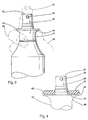
- Cap 34 of the present invention is placed on a container 30 substantially identical to container 10 shown in Figure 2.
- container 30 has a cylindrical body 32 while passing through cap 34 there is provided a plunger 36 having finger rest 37 thereon and a dispensing aperture 38.
- Cap 34 includes a generally annular side wall 40 while, at its upper end thereof, there is provided an outwardly extending flange generally designated by reference numeral 42.
- Flange 42 includes an annular flange side wall 44. Extending downwardly from annular flange side wall 44 is a bottom wall 46 which merges arcuately with side wall 40 of cap 34.
- a lip 48 Located at the upper peripheral edge of flange side wall 44 is a lip 48 which encloses a recess 50 formed in the top surface of flange 42. Mounted in recess 50 is an absorbent material such as foam 52. As may be seen , foam 52 will absorb any liquid which may drip from dispensing aperture 38 of plunger 36.
- a cover member 54 may be provided for protecting plunger 36 when not in use as is well known in the art.
- index finger 56 of the user is placed on finger rest 37 of plunger 36.
- Middle finger 60 will abut the underside of flange 42 while thumb 58 may likewise be placed in a position against the underside of flange 42.
- thumb 58 may likewise be placed in a position against the underside of flange 42.
- Flange 42 also serves to substantially prevent container 30 from becoming slippery due to moisture.
- absorbent foam 52 further aids in the above.
Landscapes
- Engineering & Computer Science (AREA)
- Mechanical Engineering (AREA)
- Containers And Packaging Bodies Having A Special Means To Remove Contents (AREA)
- Closures For Containers (AREA)
Applications Claiming Priority (2)
| Application Number | Priority Date | Filing Date | Title |
|---|---|---|---|
| US13101099P | 1999-04-26 | 1999-04-26 | |
| US131010P | 1999-04-26 |
Publications (2)
| Publication Number | Publication Date |
|---|---|
| EP1057739A2 true EP1057739A2 (de) | 2000-12-06 |
| EP1057739A3 EP1057739A3 (de) | 2001-04-04 |
Family
ID=22447465
Family Applications (1)
| Application Number | Title | Priority Date | Filing Date |
|---|---|---|---|
| EP00108531A Withdrawn EP1057739A3 (de) | 1999-04-26 | 2000-04-19 | Behälterkappe mit das Abrutschen verhindernden Flansch |
Country Status (2)
| Country | Link |
|---|---|
| EP (1) | EP1057739A3 (de) |
| CA (1) | CA2280311A1 (de) |
Cited By (3)
| Publication number | Priority date | Publication date | Assignee | Title |
|---|---|---|---|---|
| FR2814158A1 (fr) * | 2000-09-21 | 2002-03-22 | Rexam Sofab | Dispositif de prehension pour distributeur a poche souple |
| WO2005072880A1 (en) * | 2004-01-16 | 2005-08-11 | The Procter & Gamble Company | Easy operating pump or spray container |
| NL1026093C2 (nl) * | 2004-04-29 | 2005-11-01 | Airspray Nv | Afgifte-inrichting. |
Citations (2)
| Publication number | Priority date | Publication date | Assignee | Title |
|---|---|---|---|---|
| GB2232906A (en) * | 1989-06-05 | 1991-01-02 | Cheng Tsu Chen | Spraying apparatus |
| WO1998043882A1 (en) * | 1997-04-01 | 1998-10-08 | Classic Product Kft | Container provided with dispensing cap, preferably for drinks |
-
1999
- 1999-08-17 CA CA002280311A patent/CA2280311A1/en not_active Abandoned
-
2000
- 2000-04-19 EP EP00108531A patent/EP1057739A3/de not_active Withdrawn
Patent Citations (2)
| Publication number | Priority date | Publication date | Assignee | Title |
|---|---|---|---|---|
| GB2232906A (en) * | 1989-06-05 | 1991-01-02 | Cheng Tsu Chen | Spraying apparatus |
| WO1998043882A1 (en) * | 1997-04-01 | 1998-10-08 | Classic Product Kft | Container provided with dispensing cap, preferably for drinks |
Cited By (9)
| Publication number | Priority date | Publication date | Assignee | Title |
|---|---|---|---|---|
| FR2814158A1 (fr) * | 2000-09-21 | 2002-03-22 | Rexam Sofab | Dispositif de prehension pour distributeur a poche souple |
| WO2002024342A1 (fr) * | 2000-09-21 | 2002-03-28 | Rexam Dispensing Systems | Dispositif de prehension pour distributeur a poche souple |
| US6932247B2 (en) | 2000-09-21 | 2005-08-23 | Rexam Dispensing Systems | Gripping device for flexible bag dispenser |
| WO2005072880A1 (en) * | 2004-01-16 | 2005-08-11 | The Procter & Gamble Company | Easy operating pump or spray container |
| NL1026093C2 (nl) * | 2004-04-29 | 2005-11-01 | Airspray Nv | Afgifte-inrichting. |
| WO2005105320A1 (en) * | 2004-04-29 | 2005-11-10 | Airspray N.V. | Dispensing device |
| JP2007534482A (ja) * | 2004-04-29 | 2007-11-29 | エアースプレー・エヌ・ブイ | 吐出装置 |
| US8490833B2 (en) | 2004-04-29 | 2013-07-23 | Airspray N.V. | Dispensing device |
| EP2357041A3 (de) * | 2004-04-29 | 2017-10-04 | Airspray N.V. | Spender |
Also Published As
| Publication number | Publication date |
|---|---|
| EP1057739A3 (de) | 2001-04-04 |
| CA2280311A1 (en) | 2000-10-26 |
Similar Documents
| Publication | Publication Date | Title |
|---|---|---|
| EP1156981B1 (de) | Greifanordnung an sprühdose | |
| US4941600A (en) | Dispenser lock assembly for a pressurized container | |
| US20050189314A1 (en) | Attachable grip for bottles | |
| US20010054621A1 (en) | Container cap with anti-slip flange | |
| US20130341381A1 (en) | Clip handle for bag-in-box container | |
| WO1991019573A1 (en) | Nail fluid bottle cover | |
| JPH05270577A (ja) | 適量分与装置 | |
| US5441178A (en) | Overcap for pump style dispenser | |
| US20040227012A1 (en) | Fluid dispensing device | |
| EP0280551A2 (de) | Kombination eines Behälters mit einer Pompe | |
| US20070041774A1 (en) | Device for applying a substance disposed within a liquid container to an applicator | |
| US20120018453A1 (en) | Aerosol dispenser | |
| JP2004509028A (ja) | 柔軟なバック分配器のためのグリップ装置 | |
| EP1057739A2 (de) | Behälterkappe mit das Abrutschen verhindernden Flansch | |
| EP1023946A3 (de) | Flüssigkeits- Abgabevorrichtung mit einer leicht ausstellbaren Rastverbindung | |
| JP4059643B2 (ja) | 噴出容器 | |
| US3235132A (en) | Cap for an aerosol can | |
| US5941426A (en) | Liquid dispensing device | |
| US20050153259A1 (en) | Capped syringe tip for dispensing and applying liquid or viscous materials | |
| US20060151419A1 (en) | Bottle | |
| JP3406264B2 (ja) | ポンプと可撓性リザーバを備えた製品収容分配装置 | |
| JPS591541Y2 (ja) | 手動噴霧器と調髪具の組合せ | |
| EP1541244A1 (de) | Hubkolbenpumpen-ausgusseinheit | |
| WO2004022141A1 (en) | Nasal sprays | |
| CA2266926A1 (en) | Dispenser for liquid containers usable with one hand |
Legal Events
| Date | Code | Title | Description |
|---|---|---|---|
| PUAI | Public reference made under article 153(3) epc to a published international application that has entered the european phase |
Free format text: ORIGINAL CODE: 0009012 |
|
| AK | Designated contracting states |
Kind code of ref document: A2 Designated state(s): DE ES FR GB IT |
|
| AX | Request for extension of the european patent |
Free format text: AL;LT;LV;MK;RO;SI |
|
| PUAL | Search report despatched |
Free format text: ORIGINAL CODE: 0009013 |
|
| AK | Designated contracting states |
Kind code of ref document: A3 Designated state(s): AT BE CH CY DE DK ES FI FR GB GR IE IT LI LU MC NL PT SE |
|
| AX | Request for extension of the european patent |
Free format text: AL;LT;LV;MK;RO;SI |
|
| RIC1 | Information provided on ipc code assigned before grant |
Free format text: 7B 65D 83/16 A, 7B 65D 47/40 B, 7B 65D 23/06 B, 7B 65D 47/00 B |
|
| 17P | Request for examination filed |
Effective date: 20010906 |
|
| AKX | Designation fees paid |
Free format text: DE ES FR GB IT |
|
| STAA | Information on the status of an ep patent application or granted ep patent |
Free format text: STATUS: THE APPLICATION IS DEEMED TO BE WITHDRAWN |
|
| 18D | Application deemed to be withdrawn |
Effective date: 20031104 |