EP1057573A2 - A method of mending a friction stir joint - Google Patents
A method of mending a friction stir joint Download PDFInfo
- Publication number
- EP1057573A2 EP1057573A2 EP00304379A EP00304379A EP1057573A2 EP 1057573 A2 EP1057573 A2 EP 1057573A2 EP 00304379 A EP00304379 A EP 00304379A EP 00304379 A EP00304379 A EP 00304379A EP 1057573 A2 EP1057573 A2 EP 1057573A2
- Authority
- EP
- European Patent Office
- Prior art keywords
- mending
- joining
- friction stir
- bead
- members
- Prior art date
- Legal status (The legal status is an assumption and is not a legal conclusion. Google has not performed a legal analysis and makes no representation as to the accuracy of the status listed.)
- Withdrawn
Links
Images

Classifications
-
- B—PERFORMING OPERATIONS; TRANSPORTING
- B23—MACHINE TOOLS; METAL-WORKING NOT OTHERWISE PROVIDED FOR
- B23K—SOLDERING OR UNSOLDERING; WELDING; CLADDING OR PLATING BY SOLDERING OR WELDING; CUTTING BY APPLYING HEAT LOCALLY, e.g. FLAME CUTTING; WORKING BY LASER BEAM
- B23K20/00—Non-electric welding by applying impact or other pressure, with or without the application of heat, e.g. cladding or plating
- B23K20/12—Non-electric welding by applying impact or other pressure, with or without the application of heat, e.g. cladding or plating the heat being generated by friction; Friction welding
- B23K20/122—Non-electric welding by applying impact or other pressure, with or without the application of heat, e.g. cladding or plating the heat being generated by friction; Friction welding using a non-consumable tool, e.g. friction stir welding
- B23K20/1265—Non-butt welded joints, e.g. overlap-joints, T-joints or spot welds
-
- B—PERFORMING OPERATIONS; TRANSPORTING
- B23—MACHINE TOOLS; METAL-WORKING NOT OTHERWISE PROVIDED FOR
- B23K—SOLDERING OR UNSOLDERING; WELDING; CLADDING OR PLATING BY SOLDERING OR WELDING; CUTTING BY APPLYING HEAT LOCALLY, e.g. FLAME CUTTING; WORKING BY LASER BEAM
- B23K20/00—Non-electric welding by applying impact or other pressure, with or without the application of heat, e.g. cladding or plating
- B23K20/12—Non-electric welding by applying impact or other pressure, with or without the application of heat, e.g. cladding or plating the heat being generated by friction; Friction welding
- B23K20/122—Non-electric welding by applying impact or other pressure, with or without the application of heat, e.g. cladding or plating the heat being generated by friction; Friction welding using a non-consumable tool, e.g. friction stir welding
-
- B—PERFORMING OPERATIONS; TRANSPORTING
- B23—MACHINE TOOLS; METAL-WORKING NOT OTHERWISE PROVIDED FOR
- B23K—SOLDERING OR UNSOLDERING; WELDING; CLADDING OR PLATING BY SOLDERING OR WELDING; CUTTING BY APPLYING HEAT LOCALLY, e.g. FLAME CUTTING; WORKING BY LASER BEAM
- B23K9/00—Arc welding or cutting
- B23K9/04—Welding for other purposes than joining, e.g. built-up welding
-
- Y—GENERAL TAGGING OF NEW TECHNOLOGICAL DEVELOPMENTS; GENERAL TAGGING OF CROSS-SECTIONAL TECHNOLOGIES SPANNING OVER SEVERAL SECTIONS OF THE IPC; TECHNICAL SUBJECTS COVERED BY FORMER USPC CROSS-REFERENCE ART COLLECTIONS [XRACs] AND DIGESTS
- Y10—TECHNICAL SUBJECTS COVERED BY FORMER USPC
- Y10T—TECHNICAL SUBJECTS COVERED BY FORMER US CLASSIFICATION
- Y10T29/00—Metal working
- Y10T29/49—Method of mechanical manufacture
- Y10T29/49718—Repairing
- Y10T29/49721—Repairing with disassembling
- Y10T29/49723—Repairing with disassembling including reconditioning of part
- Y10T29/49725—Repairing with disassembling including reconditioning of part by shaping
- Y10T29/49726—Removing material
Definitions
- the present invention relates to a method of mending a friction stir joint and in particularly to mending of a friction stir joint of members which employ an aluminum alloy material as a base member.
- the joint is formed by rotating a round rod (called a rotary tool) which is inserted into a joining portion of two members to be subjected to a friction stir joining, such as aluminum alloy extruded frame members, and moving the rotary tool along a joining line of the two members.
- the friction stir joining portion of the two members is thus heated, softened and plastically fluidized.
- the rotary tool has a small diameter portion which is inserted into the friction stir joining portion of the two members and a large diameter portion which is adjacent and coaxial with the small diameter portion.
- the boundary or shoulder between the small diameter portion and the large diameter portion of the rotary tool is inserted a little way into the friction stir joining portion of the two members.
- the rotary tool is inclined towards the rear with respect to its advancing direction during joining of the two members.
- a third plate is arranged on the two extruded frame members and the friction stir joining is carried out on the two extruded frame members and the third plate.
- a supporting cross-member which is orthogonal to a face plate of the hollow frame member may be provided integrally and then bending of the face plate of the hollow frame member by the force of the friction stir joining can be prevented.
- Fig. 9 of the present application shows a technique for joining a side structure of a railway car 10 by friction stir joining.
- extruded frame members 20 and 30 a first extruded frame member 20 and a second extruded frame member 30
- extruded frame members 20 and 30 are manufactured by extruding and molding, for example, aluminum alloy (A6N01 material) and are joined at respective side edge portions along a joining line 40 of the extruded frame members 20, 30 by friction stir joining.
- a joining bead 50 (Fig. 10) is formed between the first and second extruded frame members 20, 30.
- the members have raised portions or ribs 22,32 at their edges where the joint is formed.
- the above stated A6N01 material is used as a railway car material, since a complicated cross-sectional shape of the large thin hollow frame member can be obtained, with high anti-corrosion performance and a good welding performance.
- the chemical composition of the A6N01 material is 0.40-0.9% Si, less than 0.35% Fe, less than 0.35% Cu, less than 0.50% Mn, 0.40-0.8% Mg, less than 0.3% Cr, less than 0.25% Zn, less than 0.10% Ti, balance Al and inevitable impurities.
- This material has the standard no. H4100 in the JIS standard for aluminum and aluminum alloy extruded frame members.
- the joining bead 50 of the first extruded frame member 20 and the second extruded frame member 30 is inspected. If there is no defect it can be left as it is.
- a defect is discovered in the joining bead 50, by mending of the defect on the joining bead 50 and, by a hairline processing etc., a surface of the extruded frame members 20, 30 having a good appearance can be obtained.
- Fig. 4 shows a state in which the friction stir joining is performed along to the joining line 40 of the extruded frame members 20, 30 to form the joining bead 50 between them.
- This joining bead 50 is inspected, for example, by an ultrasonic defect inspection process.
- a defect 60 shown in Fig. 5 may be discovered in the joining bead 50.
- Figs. 1 to 7 (except for Fig. 3), lines showing the edges of the raised portions 22,32 are omitted, for simplicity.
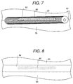
- Fig. 6 and Fig. 7 show a conventional mending process of a defect 60 which is discovered on the joining bead 50.
- the joining bead 50 which is formed by the friction stir joining is also comprised of the same A6N01 material.
- a part including this defect portion is processed using a tool such as a grinder and a mending zone 70 is formed.
- MIG welding metal inert gas welding
- a mending bead 80 is formed.
- a welding wire suited to MIG welding is used.
- the material having the A5356 composition is used (no. Z3232 of JIS standard for aluminum and aluminum alloy welding rod and wire).
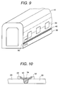
- Fig. 8 shows a state in which at the joining portion including the mended joining bead 50 a hairline processing 52 is performed.
- Hairline processing is a finishing process, known in this field.
- the hairline processing 52 provides a surface which is highly homogeneous with respect to the surfaces of the first and second extruded frame members so that even when unpainted the surface can be used as the side structure of the railway car 10.
- the surface of a mended portion 82 shown in Fig. 8 exhibits a different appearance relative to the surface of the periphery of the mended portion 82. Because of this outer appearance of the mended portion, when the side structure of the railway car 10 is left unpainted, there is a problem of an unattractive appearance.
- An object of the present invention is to provide a method of mending a friction stir joint in which the above stated problems can be solved.
- Another object of the present invention is to provide a method of mending a friction stir joint by which a defect of the friction stir joint can be removed.
- a further object of the present invention is to provide a method of mending a friction stir joint by which a defect of a joining bead of the friction stir joint of two members subjected to friction stir joining can be removed.
- a mending method of a friction stir joining portion according to the present invention which is formed by using a friction stir joining comprises a step of forming a mending zone by removing a defect which is included in a joining bead according to a grinding processing, and a step of forming a mending bead in the formed mending zone according to TIG welding (tungsten inert gas welding) using a welding rod which is the same material to the base member.
- TIG welding tungsten inert gas welding
- a mending method of a friction stir joining portion further includes a step of performing a hairline processing to a joining portion which includes the mending bead and the joining bead.
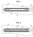
- Fig. 1 and Fig. 2 friction stir joining has been performed at a joining line 40 of a first extruded frame member 20 an a second extruded frame member 30, which are part of a side structure of a railway car 10, and a joining bead 50 is formed at the joining line 40.
- Fig. 9 discussed above shows how the members 20 and 30 are part of a side structure of a railway car 10.
- the cross-sectional view of Fig. 10 shows how side end portions of the first and second extruded frame members 20, 30 with respective pre-formed raised portions 22, 32 are abutted, and then the joining bead 50 is formed by the friction stir joining.
- the raised joint portion is made into a flat face 54 by grinding, etc.
- the raised joint portion may be left as it is.
- the joining bead 50 is formed of the same A6N01 material which is the base material of the extruded frame members 20, 30. After its formation the bead 50 is inspected. This inspection of the joining bead 50 can be carried out either with the raised portions 22, 32 remaining or after these raised portions have been removed.
- the periphery of the joining bead 50 including the defect is removed e.g. by grinding using a grinder, and then a mending zone 70 is formed.
- a mending bead 100 is formed by TIG welding (tungsten inert gas welding). Namely, a butt welding is carried out on the mending zone 70.
- a welding rod made of A6N01 material similar to the base member is prepared and used.
- This TIG welding rod made of A6N01 material may be made by cutting off a redundant portion of one of the extruded frame members 20, 30.
- the joining bead 50 and the mending bead 100 are formed using the same material.
- welding rod since the material of an electrode (tungsten electrode or tungsten alloy electrode) and a material of the welding rod differ from each other, welding rod having the same material as the members 20, 30 can be employed.
- the raised portions 22, 32 are removed e.g. by cutting or grinding, and at the face of the raised portion side a hairline processing is carried out.
- the traces or the marks of the mending bead 100 are not left. Accordingly the surface of the extruded frame members 20 has a high quality, and a railway car 10 having a good appearance even when unpainted can be obtained.
- the welding wire made of A6N01 material is not put on the market. Further, the combination of the frame member made of A6N01 material with the welding wire made of A6N01 material has not been proposed from the aspects of the welding strength and the welding performance.
- a redundant part of a member made of A6N01 material is cut off and it is used as the welding rod, but welding rod may be provided in another manner. Further, the inspection and the mending of the joining bead 50 may be carried out after the removal of the raised portions 22, 32 according to circumstances.
- TIG welding is used for the mending of the outer face in which the hairline processing is carried out.
- MIG welding is employed using the welding wire made of conventional AA5356 material.
- the mending of the joining bead 50 is carried out from the lower face side of Fig. 10, the mending can be carried out using the above stated TIG welding. After the TIG welding, the mending bead 100 is cut off by the grinding and is made smooth.
- a structural member or body such as an aluminum body railway car is constituted by joining hollow extruded frame members formed of aluminum alloy material, and when a defect of the joining bead made by the friction stir joining is mended, the defect portion is removed by the grinding etc. and the mending zone is formed, this mending zone is repaired using the welding rod having the same material with the frame member, so that a mending bead is formed by TIG welding.
- the joining bead according to the friction stir joining and the mending bead are formed of the same material, when the hairline processing is performed at the joining bead, the visible traces of the mending bead are not left, and a joint surface having good appearance can be obtained.
- the railway car body can be left without painting, and a body having a light weight structure and suited to recycling can be obtained.
Abstract

Description
- The present invention relates to a method of mending a friction stir joint and in particularly to mending of a friction stir joint of members which employ an aluminum alloy material as a base member.
- In the known technique of friction stir joining, also known as friction stir welding, the joint is formed by rotating a round rod (called a rotary tool) which is inserted into a joining portion of two members to be subjected to a friction stir joining, such as aluminum alloy extruded frame members, and moving the rotary tool along a joining line of the two members. The friction stir joining portion of the two members is thus heated, softened and plastically fluidized. The rotary tool has a small diameter portion which is inserted into the friction stir joining portion of the two members and a large diameter portion which is adjacent and coaxial with the small diameter portion. The boundary or shoulder between the small diameter portion and the large diameter portion of the rotary tool is inserted a little way into the friction stir joining portion of the two members. The rotary tool is inclined towards the rear with respect to its advancing direction during joining of the two members.
- When friction stir joining is carried out on two extruded frame members, a raised bead is formed at a surface of the side of the extruded frame members at which the rotary tool is inserted. For this reason, at the friction stir joining portion of the two extruded frame members the plate thickness of the extruded frame members becomes reduced. To prevent this, at an end portion of some or both extruded frame member to be subjected to friction stir joining, a raised portion or rib which projects toward the rotary tool is previously provided, and with this raised portion present the friction stir joining is carried on the two extruded frame members.
- Alternatively, in place of this raised portion to the extruded frame member, a third plate is arranged on the two extruded frame members and the friction stir joining is carried out on the two extruded frame members and the third plate.
- In friction stir joining of hollow frame members, a supporting cross-member which is orthogonal to a face plate of the hollow frame member may be provided integrally and then bending of the face plate of the hollow frame member by the force of the friction stir joining can be prevented.
- These techniques are disclosed in EP-A-0797043.
- Fig. 9 of the present application shows a technique for joining a side structure of a
railway car 10 by friction stir joining. In the side structure of therailway car 10, extrudedframe members 20 and 30 (a first extrudedframe member 20 and a second extruded frame member 30) are employed. Suchextruded frame members line 40 of theextruded frame members frame members ribs - As the extruded material, the above stated A6N01 material is used as a railway car material, since a complicated cross-sectional shape of the large thin hollow frame member can be obtained, with high anti-corrosion performance and a good welding performance. The chemical composition of the A6N01 material is 0.40-0.9% Si, less than 0.35% Fe, less than 0.35% Cu, less than 0.50% Mn, 0.40-0.8% Mg, less than 0.3% Cr, less than 0.25% Zn, less than 0.10% Ti, balance Al and inevitable impurities. This material has the standard no. H4100 in the JIS standard for aluminum and aluminum alloy extruded frame members.
- Next, the joining
bead 50 of the first extrudedframe member 20 and the second extrudedframe member 30 is inspected. If there is no defect it can be left as it is. When a defect is discovered in the joiningbead 50, by mending of the defect on the joiningbead 50 and, by a hairline processing etc., a surface of theextruded frame members - Fig. 4 shows a state in which the friction stir joining is performed along to the joining
line 40 of theextruded frame members bead 50 between them. This joiningbead 50 is inspected, for example, by an ultrasonic defect inspection process. Adefect 60 shown in Fig. 5 may be discovered in the joiningbead 50. - In Figs. 1 to 7 (except for Fig. 3), lines showing the edges of the raised
portions defect 60 which is discovered on the joiningbead 50. - When the extruded
frame members bead 50, which is formed by the friction stir joining is also comprised of the same A6N01 material. - To remove a defect in this joining
bead 50, a part including this defect portion is processed using a tool such as a grinder and amending zone 70 is formed. Next, MIG welding (metal inert gas welding) is performed and amending bead 80 is formed. In MIG welding, a welding wire suited to MIG welding is used. As a material of this welding wire, the material having the A5356 composition is used (no. Z3232 of JIS standard for aluminum and aluminum alloy welding rod and wire). - Fig. 8 shows a state in which at the joining portion including the mended joining bead 50 a
hairline processing 52 is performed. Hairline processing is a finishing process, known in this field. Desirably, thehairline processing 52 provides a surface which is highly homogeneous with respect to the surfaces of the first and second extruded frame members so that even when unpainted the surface can be used as the side structure of therailway car 10. - When the
hairline processing 52 is performed on the joiningbead 50 which has been mended using MIG welding, the surface of amended portion 82 shown in Fig. 8 exhibits a different appearance relative to the surface of the periphery of themended portion 82. Because of this outer appearance of the mended portion, when the side structure of therailway car 10 is left unpainted, there is a problem of an unattractive appearance. - An object of the present invention is to provide a method of mending a friction stir joint in which the above stated problems can be solved.
- Another object of the present invention is to provide a method of mending a friction stir joint by which a defect of the friction stir joint can be removed.
- A further object of the present invention is to provide a method of mending a friction stir joint by which a defect of a joining bead of the friction stir joint of two members subjected to friction stir joining can be removed.
- A mending method of a friction stir joining portion according to the present invention which is formed by using a friction stir joining comprises a step of forming a mending zone by removing a defect which is included in a joining bead according to a grinding processing, and a step of forming a mending bead in the formed mending zone according to TIG welding (tungsten inert gas welding) using a welding rod which is the same material to the base member.
- Further, a mending method of a friction stir joining portion according to the present invention further includes a step of performing a hairline processing to a joining portion which includes the mending bead and the joining bead.
- Embodiments of the invention will now be described by way of non-limitative example, with reference to the accompanying drawings, in which:-
- Fig. 1 is a diagrammatic view showing a mending process of a friction stir joint in one embodiment according to the present invention;
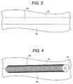
- Fig. 2 is a diagrammatic view showing a mending process of a friction stir joint in another embodiment according to the present invention;
- Fig. 3 is a diagrammatic view showing a mending process of a friction stir joint in another embodiment according to the present invention;
- Fig. 4 is a diagrammatic view of a friction stir joint;
- Fig. 5 is a diagrammatic view showing a defect of a friction stir joint;
- Fig. 6 shows diagrammatically a mending process of a friction stir joint according to the prior art;
- Fig. 7 is another view of the mending process of Fig. 6;
- Fig. 8 also shows a mending process of a friction stir joint according to the prior art;
- Fig. 9 is a diagrammatic view showing a manufacture of a side structure of a railway car, using friction stir joining; and
- Fig. 10 is a cross-sectional view on line A-A of Fig. 9.
-
- In Fig. 1 and Fig. 2 friction stir joining has been performed at a joining
line 40 of a first extrudedframe member 20 an a second extrudedframe member 30, which are part of a side structure of arailway car 10, and a joiningbead 50 is formed at the joiningline 40. Fig. 9 discussed above shows how themembers railway car 10. The cross-sectional view of Fig. 10 shows how side end portions of the first and second extrudedframe members portions bead 50 is formed by the friction stir joining. - When the sides of the
members portion railway car 10, the raised joint portion is made into aflat face 54 by grinding, etc. However, when an opposite face of the joint is formed at the outer side of therailway car 10, the raised joint portion may be left as it is. - The joining
bead 50 is formed of the same A6N01 material which is the base material of the extrudedframe members bead 50 is inspected. This inspection of the joiningbead 50 can be carried out either with the raisedportions - If by the inspection of the joining
bead 50, a defect such as a broken portion or a pit etc. on the joiningbead 50 is discovered, the periphery of the joiningbead 50 including the defect is removed e.g. by grinding using a grinder, and then amending zone 70 is formed. - Next, as shown in Fig. 2, at the mending zone 70 a
mending bead 100 is formed by TIG welding (tungsten inert gas welding). Namely, a butt welding is carried out on themending zone 70. - When this TIG welding is carried out, a welding rod made of A6N01 material similar to the base member is prepared and used. This TIG welding rod made of A6N01 material may be made by cutting off a redundant portion of one of the extruded
frame members - In accordance with this TIG welding, the joining
bead 50 and the mendingbead 100 are formed using the same material. In TIG welding, since the material of an electrode (tungsten electrode or tungsten alloy electrode) and a material of the welding rod differ from each other, welding rod having the same material as themembers - Then, if necessary the raised
portions - As a result, at the hairline processed
portion 54 shown in Fig. 3 which has been obtained by performing the hairline processing at the joining bead portion, the traces or the marks of the mendingbead 100 are not left. Accordingly the surface of the extrudedframe members 20 has a high quality, and arailway car 10 having a good appearance even when unpainted can be obtained. - With the extruded frame members made of A6N01 material, when MIG welding is carried out, a welding wire made of AA5356 material is used. This combination is recommended by the welding wire makers. The above stated combination is best from the aspects of the welding strength.
- As to the combination of the frame member made of A6N01 material with the welding wire made of A6N01 material, the welding wire made of A6N01 material is not put on the market. Further, the combination of the frame member made of A6N01 material with the welding wire made of A6N01 material has not been proposed from the aspects of the welding strength and the welding performance.
- As mentioned, within the present invention, a redundant part of a member made of A6N01 material is cut off and it is used as the welding rod, but welding rod may be provided in another manner. Further, the inspection and the mending of the joining
bead 50 may be carried out after the removal of the raisedportions - In the extruded
frame members - As shown in Fig. 10, when the friction stir joining is carried out by approaching a tip end of the small diameter portion of the rotary tool to a support bed, the face at the lower side of the
frame members railway car 10, at which the hairline processing is carried out. - When the mending of the joining
bead 50 is carried out from the lower face side of Fig. 10, the mending can be carried out using the above stated TIG welding. After the TIG welding, the mendingbead 100 is cut off by the grinding and is made smooth. - As stated above, according to the present invention, when a structural member or body such as an aluminum body railway car is constituted by joining hollow extruded frame members formed of aluminum alloy material, and when a defect of the joining bead made by the friction stir joining is mended, the defect portion is removed by the grinding etc. and the mending zone is formed, this mending zone is repaired using the welding rod having the same material with the frame member, so that a mending bead is formed by TIG welding.
- Since the joining bead according to the friction stir joining and the mending bead are formed of the same material, when the hairline processing is performed at the joining bead, the visible traces of the mending bead are not left, and a joint surface having good appearance can be obtained.
- Accordingly, the railway car body can be left without painting, and a body having a light weight structure and suited to recycling can be obtained.
Claims (4)
- A method of mending a friction stir joint between members (20, 30) formed of an aluminium alloy, the joint having a joining bead (50) formed by friction stir joining, comprising the steps of(i) forming a mending zone by removing a defect in said joining bead (50) by grinding, and(ii) forming a mending bead at said mending zone by TIG welding using a welding rod which is made of the same aluminium alloy as said members (20, 30).
- A method according to claim 1, which includes a further step of performing hairline processing of said mending bead and joining bead at the region of the mending.
- A method according to claim 1 or 2, wherein said members (20, 30) are frame members.
- A method according to claim 3, wherein said frame members (20, 30) are extruded frame members and said aluminium alloy is A6N01.
Applications Claiming Priority (2)
| Application Number | Priority Date | Filing Date | Title |
|---|---|---|---|
| JP14575999A JP3459193B2 (en) | 1999-05-26 | 1999-05-26 | Method of repairing friction stir welding and method of manufacturing railway vehicle |
| JP14575999 | 1999-05-26 |
Publications (2)
| Publication Number | Publication Date |
|---|---|
| EP1057573A2 true EP1057573A2 (en) | 2000-12-06 |
| EP1057573A3 EP1057573A3 (en) | 2003-04-02 |
Family
ID=15392513
Family Applications (1)
| Application Number | Title | Priority Date | Filing Date |
|---|---|---|---|
| EP00304379A Withdrawn EP1057573A3 (en) | 1999-05-26 | 2000-05-24 | A method of mending a friction stir joint |
Country Status (7)
| Country | Link |
|---|---|
| US (1) | US6422449B1 (en) |
| EP (1) | EP1057573A3 (en) |
| JP (1) | JP3459193B2 (en) |
| KR (1) | KR20010039622A (en) |
| CN (1) | CN1177667C (en) |
| AU (1) | AU769779B2 (en) |
| TW (1) | TW440485B (en) |
Cited By (16)
| Publication number | Priority date | Publication date | Assignee | Title |
|---|---|---|---|---|
| EP1295670A2 (en) * | 2001-09-25 | 2003-03-26 | Hitachi, Ltd. | Nondestructive inspection method |
| US6648206B2 (en) | 2000-05-08 | 2003-11-18 | Tracey W. Nelson | Friction stir welding using a superabrasive tool |
| US6722555B2 (en) * | 2000-03-06 | 2004-04-20 | Hitachi, Ltd. | Friction stir welding method |
| US7225968B2 (en) | 2003-08-04 | 2007-06-05 | Sii Megadiamond, Inc. | Crack repair using friction stir welding on materials including metal matrix composites, ferrous alloys, non-ferrous alloys, and superalloys |
| US7270257B2 (en) | 2003-01-30 | 2007-09-18 | Sii Megadiamond, Inc. | Out-of-position friction stir welding of high melting temperature alloys |
| CN100439030C (en) * | 2006-05-17 | 2008-12-03 | 崔学斌 | Technique for repairing surface damage on piston rod of hydraulic ram, and dedicated repairing tools |
| EP2000245A2 (en) * | 2006-03-09 | 2008-12-10 | Taiyo Nippon Sanso Corporation | Welding method |
| US7523554B2 (en) | 2003-06-17 | 2009-04-28 | Honda Motor Co., Ltd. | Method of manufacturing a wheel rim |
| US7530486B2 (en) | 2003-05-05 | 2009-05-12 | Sii Megadiamond, Inc. | Applications of friction stir welding using a superabrasive tool |
| US7608296B2 (en) | 2001-06-12 | 2009-10-27 | Brigham Young University | Anvil for friction stir welding high temperature materials |
| US7651018B2 (en) | 2004-10-05 | 2010-01-26 | Sii Megadiamond | Expandable mandrel for use in friction stir welding |
| US8056797B2 (en) | 2005-10-05 | 2011-11-15 | Megastir Technologies | Expandable mandrel for use in friction stir welding |
| US8186561B2 (en) | 2004-03-24 | 2012-05-29 | Megastir Technologies, LLC | Solid state processing of hand-held knife blades to improve blade performance |
| CN101772395B (en) * | 2007-08-10 | 2013-01-16 | 日本轻金属株式会社 | Joining method, and joined structure manufacturing method |
| US8550326B2 (en) | 2005-10-05 | 2013-10-08 | Megastir Technologies Llc | Expandable mandrel for use in friction stir welding |
| US8955734B2 (en) | 2004-05-21 | 2015-02-17 | Smith International, Inc. | Ball hole welding using the friction stir welding (FSW) process |
Families Citing this family (32)
| Publication number | Priority date | Publication date | Assignee | Title |
|---|---|---|---|---|
| CN1310732C (en) * | 1996-03-19 | 2007-04-18 | 株式会社日立制作所 | Friction welding method |
| JP2003048063A (en) * | 2001-08-01 | 2003-02-18 | Mazda Motor Corp | Surface treatment method, member applied with the surface treatment and intermediate member applied with the surface treatment |
| US7000303B2 (en) * | 2002-10-24 | 2006-02-21 | The Boeing Company | Method of repairing a crack in a component utilizing friction stir welding |
| US7122761B2 (en) * | 2002-11-12 | 2006-10-17 | Siemens Power Generation, Inc. | Friction processing weld preparation |
| US6908145B2 (en) * | 2003-02-10 | 2005-06-21 | Ford Global Technologies, Llc | Vehicle passenger compartment components and manufacturing process for making the same |
| JP2004261900A (en) * | 2003-02-28 | 2004-09-24 | Hitachi Ltd | Hairline machining method and device for the same |
| US20050070374A1 (en) * | 2003-09-29 | 2005-03-31 | Technology Licensing, Llc | Enhanced golf club performance via friction stir processing |
| GB0414913D0 (en) * | 2004-07-01 | 2004-08-04 | Rolls Royce Plc | A method of welding onto thin components |
| CN100335228C (en) * | 2005-04-28 | 2007-09-05 | 上海交通大学 | Tungsten pole inert gas protection electric arc welding preheating stirring friction welding composite method |
| CN100351034C (en) * | 2005-07-11 | 2007-11-28 | 哈尔滨工业大学 | Plasma arc-stirring friction composition welding method |
| US9511445B2 (en) | 2014-12-17 | 2016-12-06 | Aeroprobe Corporation | Solid state joining using additive friction stir processing |
| US8875976B2 (en) | 2005-09-26 | 2014-11-04 | Aeroprobe Corporation | System for continuous feeding of filler material for friction stir welding, processing and fabrication |
| US20080041921A1 (en) | 2005-09-26 | 2008-02-21 | Kevin Creehan | Friction stir fabrication |
| US9511446B2 (en) | 2014-12-17 | 2016-12-06 | Aeroprobe Corporation | In-situ interlocking of metals using additive friction stir processing |
| US8632850B2 (en) | 2005-09-26 | 2014-01-21 | Schultz-Creehan Holdings, Inc. | Friction fabrication tools |
| US9266191B2 (en) | 2013-12-18 | 2016-02-23 | Aeroprobe Corporation | Fabrication of monolithic stiffening ribs on metallic sheets |
| US8281977B2 (en) * | 2006-10-02 | 2012-10-09 | Nippon Light Metal Company, Ltd. | Joining method and friction stir welding method |
| US7555359B2 (en) * | 2006-10-06 | 2009-06-30 | Hitachi, Ltd | Apparatus and method for correcting defects by friction stir processing |
| JP4578493B2 (en) * | 2007-03-16 | 2010-11-10 | 川崎重工業株式会社 | Railcar exterior |
| JP2013509301A (en) | 2009-11-02 | 2013-03-14 | メガスター・テクノロジーズ・エルエルシー | Misalignment friction stir welding of casing and small diameter pipes or small diameter pipes |
| DE102010032402A1 (en) * | 2010-07-27 | 2012-02-02 | Airbus Operations Gmbh | Method of joining two aircraft body segments by means of friction stir welding |
| WO2013002869A2 (en) | 2011-04-07 | 2013-01-03 | Schultz-Creehan Holdings, Inc. | System for continuous feeding of filler material for friction stir fabrication and self-reacting friction stir welding tool |
| WO2013027532A1 (en) * | 2011-08-19 | 2013-02-28 | 日本軽金属株式会社 | Friction stir welding method |
| FR2980382B1 (en) * | 2011-09-27 | 2013-10-11 | Snecma | METHOD FOR WELDING AND RECHARGING ALUMINUM METALLIC PARTS BY MIG METHOD WITH CURRENT AND PULSED DELIVERY WIRE |
| CN102513688A (en) * | 2011-11-22 | 2012-06-27 | 长春轨道客车股份有限公司 | Keyhole repairing welding method for friction stir welding of thick plate aluminum alloy |
| JP5789495B2 (en) * | 2011-11-24 | 2015-10-07 | 株式会社日立製作所 | How to repair welds |
| CN102785016B (en) * | 2012-08-17 | 2015-03-18 | 中联重科股份有限公司 | Structural container and welding method thereof |
| CN104070000B (en) * | 2013-03-29 | 2016-02-03 | 东莞市永强汽车制造有限公司 | A kind of coating process keeping aluminium alloy tank car primary colors |
| CN104117749B (en) * | 2014-08-13 | 2016-03-02 | 成都四威高科技产业园有限公司 | A kind of rewelding method of aluminium alloy sealed welding seam |
| CN106475678B (en) * | 2016-11-02 | 2021-10-01 | 上海航天设备制造总厂 | Method for removing cracks of leading-in and leading-out interfaces of friction stir welding |
| KR102273514B1 (en) | 2017-10-31 | 2021-07-06 | 멜드 매뉴팩쳐링 코포레이션 | Solid-State Additive Manufacturing Systems and Material Compositions and Structures |
| CN110977138A (en) * | 2019-11-15 | 2020-04-10 | 唐山宏正机械设备有限公司 | Aluminum alloy double-shaft-shoulder friction stir welding defect repairing method |
Citations (2)
| Publication number | Priority date | Publication date | Assignee | Title |
|---|---|---|---|---|
| EP0797043A2 (en) * | 1996-03-19 | 1997-09-24 | Hitachi, Ltd. | Panel structure, a friction welding method, and a panel |
| US5674419A (en) * | 1994-07-05 | 1997-10-07 | Hitachi, Ltd. | Method for weld repairing of structures in nuclear reactors |
Family Cites Families (14)
| Publication number | Priority date | Publication date | Assignee | Title |
|---|---|---|---|---|
| CN1010760B (en) * | 1984-11-13 | 1990-12-12 | 三菱电机株式会社 | Method for manufacturing a decorative sheet |
| US5267279A (en) * | 1990-01-12 | 1993-11-30 | Hitachi, Ltd. | Method and structure for repairing an elongated metal hollow member |
| US5215243A (en) * | 1990-08-31 | 1993-06-01 | Electric Power Research Institute, Inc. | Hot isostatic bonding process for repairing shafts |
| US5085363A (en) * | 1990-11-01 | 1992-02-04 | Westinghouse Electric Corp. | Method of weld repairing of a section of a metallic cylindrical member |
| JP2808943B2 (en) * | 1991-09-25 | 1998-10-08 | トヨタ自動車株式会社 | Panel manufacturing method |
| JP2601741B2 (en) * | 1991-12-18 | 1997-04-16 | 新日本製鐵株式会社 | Rail repair welding method |
| JP3074930B2 (en) * | 1992-04-09 | 2000-08-07 | トヨタ自動車株式会社 | Welding panel manufacturing equipment capable of manufacturing two or more types |
| US5322539A (en) * | 1992-06-26 | 1994-06-21 | Desert Glassworks, Inc. | Quartz tank member and method of production thereof |
| US5359815A (en) * | 1992-11-06 | 1994-11-01 | Harsco Corporation | Profile grinder |
| US5391887A (en) * | 1993-02-10 | 1995-02-21 | Trustees Of Princeton University | Method and apparatus for the management of hazardous waste material |
| US5565749A (en) * | 1993-04-28 | 1996-10-15 | Kabushiki Kaisha Toshiba | Method of controlling a grinder robot |
| US5597529A (en) * | 1994-05-25 | 1997-01-28 | Ashurst Technology Corporation (Ireland Limited) | Aluminum-scandium alloys |
| US5453243A (en) * | 1994-08-17 | 1995-09-26 | The United States Of America As Represented By The Secretary Of The Interior | Method for producing titanium aluminide weld rod |
| JP3070735B2 (en) * | 1997-07-23 | 2000-07-31 | 株式会社日立製作所 | Friction stir welding method |
-
1999
- 1999-05-26 JP JP14575999A patent/JP3459193B2/en not_active Expired - Fee Related
-
2000
- 2000-02-01 TW TW089101750A patent/TW440485B/en not_active IP Right Cessation
- 2000-03-01 CN CNB00103667XA patent/CN1177667C/en not_active Expired - Fee Related
- 2000-05-15 AU AU35309/00A patent/AU769779B2/en not_active Ceased
- 2000-05-24 EP EP00304379A patent/EP1057573A3/en not_active Withdrawn
- 2000-05-25 KR KR1020000028389A patent/KR20010039622A/en not_active Application Discontinuation
- 2000-11-17 US US09/714,610 patent/US6422449B1/en not_active Expired - Fee Related
Patent Citations (2)
| Publication number | Priority date | Publication date | Assignee | Title |
|---|---|---|---|---|
| US5674419A (en) * | 1994-07-05 | 1997-10-07 | Hitachi, Ltd. | Method for weld repairing of structures in nuclear reactors |
| EP0797043A2 (en) * | 1996-03-19 | 1997-09-24 | Hitachi, Ltd. | Panel structure, a friction welding method, and a panel |
Cited By (26)
| Publication number | Priority date | Publication date | Assignee | Title |
|---|---|---|---|---|
| US6722555B2 (en) * | 2000-03-06 | 2004-04-20 | Hitachi, Ltd. | Friction stir welding method |
| US6786388B2 (en) | 2000-03-06 | 2004-09-07 | Hitachi, Ltd. | Friction stir welding method |
| US7993575B2 (en) | 2000-05-08 | 2011-08-09 | Megastir Technologies, LLC | Friction stir welding using a superabrasive tool |
| US9061370B2 (en) | 2000-05-08 | 2015-06-23 | Brigham Young University | Friction stir welding using a superabrasive tool |
| US6648206B2 (en) | 2000-05-08 | 2003-11-18 | Tracey W. Nelson | Friction stir welding using a superabrasive tool |
| US7661572B2 (en) | 2000-05-08 | 2010-02-16 | Brigham Young University | Friction stir welding using a superabrasive tool |
| US7124929B2 (en) | 2000-05-08 | 2006-10-24 | Sii Megadiamond, Inc. | Friction stir welding of metal matrix composites, ferrous alloys, non-ferrous alloys, and superalloys using a superabrasive tool |
| US7152776B2 (en) | 2000-05-08 | 2006-12-26 | Sii Megadiamond, Inc. | Friction stir welding using a superabrasive tool |
| US6779704B2 (en) | 2000-05-08 | 2004-08-24 | Tracy W. Nelson | Friction stir welding of metal matrix composites, ferrous alloys, non-ferrous alloys, and superalloys using a superabrasive tool |
| US8302834B2 (en) | 2000-05-08 | 2012-11-06 | MegaStar Technologies LLC | Friction stir welding using a superabrasive tool |
| US7608296B2 (en) | 2001-06-12 | 2009-10-27 | Brigham Young University | Anvil for friction stir welding high temperature materials |
| EP1295670A2 (en) * | 2001-09-25 | 2003-03-26 | Hitachi, Ltd. | Nondestructive inspection method |
| EP1295670A3 (en) * | 2001-09-25 | 2004-12-29 | Hitachi, Ltd. | Nondestructive inspection method |
| US7270257B2 (en) | 2003-01-30 | 2007-09-18 | Sii Megadiamond, Inc. | Out-of-position friction stir welding of high melting temperature alloys |
| US7530486B2 (en) | 2003-05-05 | 2009-05-12 | Sii Megadiamond, Inc. | Applications of friction stir welding using a superabrasive tool |
| US7523554B2 (en) | 2003-06-17 | 2009-04-28 | Honda Motor Co., Ltd. | Method of manufacturing a wheel rim |
| US7225968B2 (en) | 2003-08-04 | 2007-06-05 | Sii Megadiamond, Inc. | Crack repair using friction stir welding on materials including metal matrix composites, ferrous alloys, non-ferrous alloys, and superalloys |
| US8186561B2 (en) | 2004-03-24 | 2012-05-29 | Megastir Technologies, LLC | Solid state processing of hand-held knife blades to improve blade performance |
| US8955734B2 (en) | 2004-05-21 | 2015-02-17 | Smith International, Inc. | Ball hole welding using the friction stir welding (FSW) process |
| US7651018B2 (en) | 2004-10-05 | 2010-01-26 | Sii Megadiamond | Expandable mandrel for use in friction stir welding |
| US8056797B2 (en) | 2005-10-05 | 2011-11-15 | Megastir Technologies | Expandable mandrel for use in friction stir welding |
| US8550326B2 (en) | 2005-10-05 | 2013-10-08 | Megastir Technologies Llc | Expandable mandrel for use in friction stir welding |
| EP2000245A4 (en) * | 2006-03-09 | 2009-11-04 | Taiyo Nippon Sanso Corp | Welding method |
| EP2000245A2 (en) * | 2006-03-09 | 2008-12-10 | Taiyo Nippon Sanso Corporation | Welding method |
| CN100439030C (en) * | 2006-05-17 | 2008-12-03 | 崔学斌 | Technique for repairing surface damage on piston rod of hydraulic ram, and dedicated repairing tools |
| CN101772395B (en) * | 2007-08-10 | 2013-01-16 | 日本轻金属株式会社 | Joining method, and joined structure manufacturing method |
Also Published As
| Publication number | Publication date |
|---|---|
| JP3459193B2 (en) | 2003-10-20 |
| EP1057573A3 (en) | 2003-04-02 |
| AU3530900A (en) | 2000-11-30 |
| AU769779B2 (en) | 2004-02-05 |
| US6422449B1 (en) | 2002-07-23 |
| CN1177667C (en) | 2004-12-01 |
| TW440485B (en) | 2001-06-16 |
| CN1275461A (en) | 2000-12-06 |
| KR20010039622A (en) | 2001-05-15 |
| JP2000334583A (en) | 2000-12-05 |
Similar Documents
| Publication | Publication Date | Title |
|---|---|---|
| EP1057573A2 (en) | A method of mending a friction stir joint | |
| US6745929B1 (en) | Method of manufacturing structural body and structural body | |
| EP1775061B1 (en) | Hole repair technique | |
| JP3262533B2 (en) | Aluminum alloy joining material | |
| US6892928B2 (en) | Method of manufacturing tubular body, by friction stir welding | |
| JP3217061B2 (en) | Repair method of automobile body consisting of nodal element and hollow girder | |
| JP2002059289A (en) | Method for repairing friction-stir welded part | |
| JP4134562B2 (en) | Method for manufacturing aluminum-based structure | |
| US10478919B2 (en) | Method for producing aluminum joined body | |
| JP5875302B2 (en) | Aluminum plate joining method | |
| JPS62286680A (en) | Butt welding method for aluminum thin plate | |
| US20140023874A1 (en) | Method for welding aluminum alloy materials and aluminum alloy panel produced thereby | |
| JP4437914B2 (en) | Aluminum bonding material and method of pressing aluminum bonding material | |
| JP2004224246A (en) | Suspension arm and method of manufacturing the same | |
| JP3996004B2 (en) | Differential thickness tailored blank | |
| EP2687313A1 (en) | Method of friction stir welding aluminum alloy materials containing second phase particles, and aluminum alloy panel produced thereby | |
| JP3394156B2 (en) | Welded structure and its manufacturing method | |
| JPH07266068A (en) | Method for laser beam welding aluminum or aluminum alloy member | |
| JP4036793B2 (en) | Weld Deburring Device and Method | |
| EP2364808B1 (en) | Method for preferential formation of weld join | |
| JP2001259882A (en) | Method of manufacturing for rim of large or medium sized steel wheel | |
| US20060027549A1 (en) | Buried arc welding of integrally backed square butt joints | |
| JPH1150180A (en) | Welded structure | |
| JP2000142003A (en) | Aluminum wheel for automobile and manufacture therefor | |
| JPH10244365A (en) | Welding method of thick wall pipe |
Legal Events
| Date | Code | Title | Description |
|---|---|---|---|
| PUAI | Public reference made under article 153(3) epc to a published international application that has entered the european phase |
Free format text: ORIGINAL CODE: 0009012 |
|
| 17P | Request for examination filed |
Effective date: 20000613 |
|
| AK | Designated contracting states |
Kind code of ref document: A2 Designated state(s): AT BE CH CY DE DK ES FI FR GB GR IE IT LI LU MC NL PT SE |
|
| AX | Request for extension of the european patent |
Free format text: AL;LT;LV;MK;RO;SI |
|
| PUAL | Search report despatched |
Free format text: ORIGINAL CODE: 0009013 |
|
| AK | Designated contracting states |
Kind code of ref document: A3 Designated state(s): AT BE CH CY DE DK ES FI FR GB GR IE IT LI LU MC NL PT SE Designated state(s): AT BE CH CY DE DK ES FI FR GB GR IE IT LI LU MC NL PT SE |
|
| AX | Request for extension of the european patent |
Extension state: AL LT LV MK RO SI |
|
| AKX | Designation fees paid |
Designated state(s): DE FR GB IT SE |
|
| 17Q | First examination report despatched |
Effective date: 20040914 |
|
| STAA | Information on the status of an ep patent application or granted ep patent |
Free format text: STATUS: THE APPLICATION IS DEEMED TO BE WITHDRAWN |
|
| 18D | Application deemed to be withdrawn |
Effective date: 20050125 |