EP1056590B1 - Extruder for small plant parts - Google Patents
Extruder for small plant parts Download PDFInfo
- Publication number
- EP1056590B1 EP1056590B1 EP99903688A EP99903688A EP1056590B1 EP 1056590 B1 EP1056590 B1 EP 1056590B1 EP 99903688 A EP99903688 A EP 99903688A EP 99903688 A EP99903688 A EP 99903688A EP 1056590 B1 EP1056590 B1 EP 1056590B1
- Authority
- EP
- European Patent Office
- Prior art keywords
- filling
- feed shaft
- paddles
- pressing chamber
- agitator
- Prior art date
- Legal status (The legal status is an assumption and is not a legal conclusion. Google has not performed a legal analysis and makes no representation as to the accuracy of the status listed.)
- Expired - Lifetime
Links
Images
Classifications
-
- B—PERFORMING OPERATIONS; TRANSPORTING
- B30—PRESSES
- B30B—PRESSES IN GENERAL
- B30B15/00—Details of, or accessories for, presses; Auxiliary measures in connection with pressing
- B30B15/30—Feeding material to presses
- B30B15/302—Feeding material in particulate or plastic state to moulding presses
-
- B—PERFORMING OPERATIONS; TRANSPORTING
- B27—WORKING OR PRESERVING WOOD OR SIMILAR MATERIAL; NAILING OR STAPLING MACHINES IN GENERAL
- B27N—MANUFACTURE BY DRY PROCESSES OF ARTICLES, WITH OR WITHOUT ORGANIC BINDING AGENTS, MADE FROM PARTICLES OR FIBRES CONSISTING OF WOOD OR OTHER LIGNOCELLULOSIC OR LIKE ORGANIC MATERIAL
- B27N3/00—Manufacture of substantially flat articles, e.g. boards, from particles or fibres
- B27N3/08—Moulding or pressing
- B27N3/28—Moulding or pressing characterised by using extrusion presses
-
- B—PERFORMING OPERATIONS; TRANSPORTING
- B29—WORKING OF PLASTICS; WORKING OF SUBSTANCES IN A PLASTIC STATE IN GENERAL
- B29C—SHAPING OR JOINING OF PLASTICS; SHAPING OF MATERIAL IN A PLASTIC STATE, NOT OTHERWISE PROVIDED FOR; AFTER-TREATMENT OF THE SHAPED PRODUCTS, e.g. REPAIRING
- B29C48/00—Extrusion moulding, i.e. expressing the moulding material through a die or nozzle which imparts the desired form; Apparatus therefor
- B29C48/03—Extrusion moulding, i.e. expressing the moulding material through a die or nozzle which imparts the desired form; Apparatus therefor characterised by the shape of the extruded material at extrusion
- B29C48/05—Filamentary, e.g. strands
-
- B—PERFORMING OPERATIONS; TRANSPORTING
- B29—WORKING OF PLASTICS; WORKING OF SUBSTANCES IN A PLASTIC STATE IN GENERAL
- B29C—SHAPING OR JOINING OF PLASTICS; SHAPING OF MATERIAL IN A PLASTIC STATE, NOT OTHERWISE PROVIDED FOR; AFTER-TREATMENT OF THE SHAPED PRODUCTS, e.g. REPAIRING
- B29C48/00—Extrusion moulding, i.e. expressing the moulding material through a die or nozzle which imparts the desired form; Apparatus therefor
- B29C48/03—Extrusion moulding, i.e. expressing the moulding material through a die or nozzle which imparts the desired form; Apparatus therefor characterised by the shape of the extruded material at extrusion
- B29C48/09—Articles with cross-sections having partially or fully enclosed cavities, e.g. pipes or channels
- B29C48/10—Articles with cross-sections having partially or fully enclosed cavities, e.g. pipes or channels flexible, e.g. blown foils
-
- B—PERFORMING OPERATIONS; TRANSPORTING
- B29—WORKING OF PLASTICS; WORKING OF SUBSTANCES IN A PLASTIC STATE IN GENERAL
- B29C—SHAPING OR JOINING OF PLASTICS; SHAPING OF MATERIAL IN A PLASTIC STATE, NOT OTHERWISE PROVIDED FOR; AFTER-TREATMENT OF THE SHAPED PRODUCTS, e.g. REPAIRING
- B29C48/00—Extrusion moulding, i.e. expressing the moulding material through a die or nozzle which imparts the desired form; Apparatus therefor
- B29C48/25—Component parts, details or accessories; Auxiliary operations
- B29C48/36—Means for plasticising or homogenising the moulding material or forcing it through the nozzle or die
- B29C48/475—Means for plasticising or homogenising the moulding material or forcing it through the nozzle or die using pistons, accumulators or press rams
-
- B—PERFORMING OPERATIONS; TRANSPORTING
- B30—PRESSES
- B30B—PRESSES IN GENERAL
- B30B11/00—Presses specially adapted for forming shaped articles from material in particulate or plastic state, e.g. briquetting presses, tabletting presses
- B30B11/22—Extrusion presses; Dies therefor
- B30B11/26—Extrusion presses; Dies therefor using press rams
- B30B11/265—Extrusion presses; Dies therefor using press rams with precompression means
-
- B—PERFORMING OPERATIONS; TRANSPORTING
- B29—WORKING OF PLASTICS; WORKING OF SUBSTANCES IN A PLASTIC STATE IN GENERAL
- B29C—SHAPING OR JOINING OF PLASTICS; SHAPING OF MATERIAL IN A PLASTIC STATE, NOT OTHERWISE PROVIDED FOR; AFTER-TREATMENT OF THE SHAPED PRODUCTS, e.g. REPAIRING
- B29C48/00—Extrusion moulding, i.e. expressing the moulding material through a die or nozzle which imparts the desired form; Apparatus therefor
- B29C48/25—Component parts, details or accessories; Auxiliary operations
- B29C48/285—Feeding the extrusion material to the extruder
- B29C48/288—Feeding the extrusion material to the extruder in solid form, e.g. powder or granules
- B29C48/2886—Feeding the extrusion material to the extruder in solid form, e.g. powder or granules of fibrous, filamentary or filling materials, e.g. thin fibrous reinforcements or fillers
-
- B—PERFORMING OPERATIONS; TRANSPORTING
- B29—WORKING OF PLASTICS; WORKING OF SUBSTANCES IN A PLASTIC STATE IN GENERAL
- B29K—INDEXING SCHEME ASSOCIATED WITH SUBCLASSES B29B, B29C OR B29D, RELATING TO MOULDING MATERIALS OR TO MATERIALS FOR MOULDS, REINFORCEMENTS, FILLERS OR PREFORMED PARTS, e.g. INSERTS
- B29K2105/00—Condition, form or state of moulded material or of the material to be shaped
- B29K2105/06—Condition, form or state of moulded material or of the material to be shaped containing reinforcements, fillers or inserts
Definitions
- the invention relates to a method for Extruding hollow strands from vegetable, especially small wooden parts with a horizontal acting piston extrusion press, at a feed shaft with its lower end in a filling and pressing room flows and through a reciprocating, one Closing slide with passage opening is closable, the extrusion piston on at least one, the filling and pressing room in Is passed through the extrusion direction penetrating mandrel, as well as on an extrusion press to carry out the Process.
- the invention is therefore based on the object Filling the filling and pressing room with the vegetable Small parts to improve the areas different Avoid density in the strand if possible and performance to increase the extrusion press overall.
- the method according to the invention consists of that the mandrel is designed as a heating tube, and that the vegetable small parts when filling the filling and Press room specifically in the direction of under the heating pipe located area by a in the lower part of the Feed shaft located, from two axes with parallel existing agitator paddles be promoted.
- the invention thus opens up the Possibility of filling the filling and pressing room to accelerate or improve.
- a filling device with an axis is shown in Figure 1 of the DE-GM 89 06 494.1 became known. There it will Small parts batch through an upright feed chute below towards the filling and pressing room of the extrusion press promoted. In the lower part of the feed chute is a Agitator consisting of two around a common axis rotating wings, at least temporarily rotatable driven. This agitator does the job Small parts batch in the filling and in a faster time To promote the extrusion press room than through this free fall of the batch would happen.
- the invention is therefore the additional object based on avoiding these disadvantages and filling a filling and pressing room, which contains a heating tube accelerate without the position of the heating pipe change.
- the device is based on DE-GM 89 06 494.1 to carry out the method according to the invention in that the agitator consists of two with their axes parallel paddles are positioned opposite each other rotatably drivable and staggered are, the direction of conveyance of the paddle on one Of the heating pipe penetrating the filling and pressing chamber.
- Embodiments of the invention result from the Claims 3 to 9.
- the offset of the paddles is chosen such that they are in a basic position in opposite directions extend. In this way it becomes even Loading of the filling and pressing room reached.
- the feed shaft in the The area surrounding the agitator has a hollow cylindrical shape is. Then the agitator works with greater efficiency like a wing compressor.
- the paddles can be made of rubber consist or of a hard material, e.g. Steel, be made, in the latter case recommends attaching the paddles resiliently.
- Another embodiment is claims 7 to 9 in which the feed chute is provided and a holder for the filling opening of the filling and Closing body covering the press room on an upper, extending parallel to the extrusion axis To mount the pivot axis so that it can move in a pendulum-shaped manner such that the filling opening in the end positions of the pendulum movement is either covered by the closing body or congruent to the outlet opening of the feed shaft lies.
- the principle of the swiveling feed chute is out the aforementioned DE-GM 89 06 494.1 known. There is but the pivot bearing for holding the closing body distanced from the swivel axis of the feed shaft.
- the Embodiment of the invention combines the advantages of Agitator according to the invention with a pivotable mounted closing body for covering the Filling opening of the filling and pressing room, this too Combination is particularly suitable for one through a heating mandrel equipped filling and pressing room Filling the extruder faster without closing the heating mandrel strain.
- FIG. 3 shows only that Cross section through a filling and pressing room (5) Extrusion press, as known from DE-A-28 10 070.
- the batch of small parts (3) to be pressed is located in an upright feed chute (2), the lower end of which by a closing slide (6) which can be closed Example of Figure 1 shown in the open position is.
- This closing slide (6) has a passage opening (28), the clear width of which is approximately the cross section of the Filling opening (14) of the filling and pressing room (5) equivalent. If you have the closing slide (6) as with Prior art (DE-A-28 10 070) repeatedly back and forth moved, there is a better distribution of the contents in the filling and pressing room (5).
- the filling and pressing space (5) of the extrusion press becomes centric by extending in the extrusion axis Heating tube (7) penetrates, which has the task of the warming forming strand from the inside and cure. Accordingly, that in Figure 1 is not Extrusion piston shown on this heating tube (7) guided. If the strand to be formed is wider than in figure 1, it may be recommended to use several Arrange the heating pipes (7) next to each other and the Form the extrusion piston accordingly.
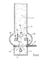
- FIG. 1 is also a upright feed shaft (2) in vertical section represented by the vegetable small parts (3) should come down to in the filling and pressing room (5) of the horizontal extrusion press.
- the small vegetable parts can be mixed with binders be, depending on the nature of the to be formed Should own strand.
- an agitator (19) which has the task of vegetable small parts (3) quickly and specifically in the Filling and pressing room (5) to promote without the position of To change the heating pipe.
- the agitator (19) consists of two spaced from each other and stored parallel to each other Shafts (20), each with a single-wing paddle (21) is attached.
- the direction of rotation (22) of the shafts (20) is directed against each other.
- the paddles (21) are in the basic position shown in Figure 1 against each other directed. In this way a flow of conveyed small parts (3) in the direction of the arrows (27) (Conveying direction).
- This conveying direction (27) is deliberately like this chosen that it targets the heating tube (7) and instead whose the lower corner areas of the press and filling room (5) filled in specifically.
- the agitator (19) shown in Figure 1 is in one hollow cylindrical shaft part (23) rotatable stored.
- the single-wing paddle (21) be dimensioned so that they are along the inner surface of the slide along the hollow cylindrical shaft part (23), but this is not absolutely necessary.
- the paddles (21) are made of rubber in one embodiment and therefore have a flexibility that the congestion small parts to be funded can be useful. But it is also conceivable, the paddles (21) made of hard material, e.g. Steel. Then it is recommended that Attach the paddles to the shafts (20) or the Storage of the shafts (20) to make it elastic to achieve certain yield when the small parts jam.
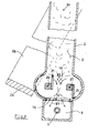
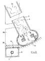
- Figures 2 deals and 3 with a swivel-mounted feed shaft (2) and with a closing slide (25), which together with its holder (26) and the feed shaft (2) from one Open position according to Figure 2 in a closed position can pivot according to Figure 3.
- the bracket (26) and the feed shaft (2) are together by one Swivel axis (24) rotatably mounted.
- the place of The pivot axis (24) is not to scale in the drawing shown.
- the feed chute (2) and the holder (26) has a substantially greater length, whereby the cam track of the closing slide (25) much flatter than shown in the drawing, runs.
- the closing slide (25) must be in the position shown in FIG Position the filling opening (14) of the filling and pressing room (5) Completely complete and on the work stroke to the Take up pressure on the walls of the recipient.
- the slide valve (25) Arrange bracket (26) adjustable in height in order to assemble to maintain the correct closed position and when worn to be able to carry out an adjustment.
- This Adjustment device is not in the drawing shown because they are carried out by usual means can be.
Landscapes
- Engineering & Computer Science (AREA)
- Mechanical Engineering (AREA)
- Life Sciences & Earth Sciences (AREA)
- Manufacturing & Machinery (AREA)
- Wood Science & Technology (AREA)
- Forests & Forestry (AREA)
- Dry Formation Of Fiberboard And The Like (AREA)
- Basic Packing Technique (AREA)
- Fertilizers (AREA)
- Agricultural Chemicals And Associated Chemicals (AREA)
- Formation And Processing Of Food Products (AREA)
- Powder Metallurgy (AREA)
- Organic Low-Molecular-Weight Compounds And Preparation Thereof (AREA)
- Solid-Sorbent Or Filter-Aiding Compositions (AREA)
- Processing And Handling Of Plastics And Other Materials For Molding In General (AREA)
- Extrusion Moulding Of Plastics Or The Like (AREA)
Abstract
Description
Die Erfindung bezieht sich auf ein Verfahren zum Strangpressen von hohlen Strängen aus pflanzlichen, insbesondere hölzernen Kleinteilen mit einer horizontal wirkenden Kolbenstrangpresse, bei der ein Zuführschacht mit seinem unteren Ende in einen Füll- und Pressraum mündet und durch einen hin- und herbeweglichen, eine Durchlassöffnung aufweisenden Schließschieber verschließbar ist, wobei der Strangpresskolben auf mindestens einem, den Füll- und Pressraum in Strangpressrichtung durchsetzenden Dorn geführt ist, sowie auf eine Strangpresse zur Durchführung des Verfahrens.The invention relates to a method for Extruding hollow strands from vegetable, especially small wooden parts with a horizontal acting piston extrusion press, at a feed shaft with its lower end in a filling and pressing room flows and through a reciprocating, one Closing slide with passage opening is closable, the extrusion piston on at least one, the filling and pressing room in Is passed through the extrusion direction penetrating mandrel, as well as on an extrusion press to carry out the Process.
Eine Strangpresse mit den vorstehenden Merkmalen ist durch die DE-A-28 10 070 bekannt.An extrusion press with the above features is through DE-A-28 10 070 is known.
Das Problem der bekannten Strangpressen dieser Art besteht darin, dass der Füll- und Pressraum nicht gleichmäßig mit den pflanzlichen Kleinteilen gefüllt wird, wodurch sich nach dem Strangpresshub Bereiche unterschiedlicher Dichte im fertigen Strang ergeben. Bedingt ist diese ungleichmäßige Befüllung durch die Anwesenheit des Dorns , welches das Zentrum des Füll- und Pressraumes in Strangpressrichtung durchsetzt. Das im freien Fall aus dem Zuführschacht herangeführte pflanzliche Material muß diesem Dorn ausweichen und kann dann nicht mehr den Bereich unterhalb des Dornes genügend ausfüllen. The problem with the known extrusion presses of this type exists in that the filling and pressing room is not even with the vegetable small parts is filled, which makes after the extrusion stroke areas of different densities result in the finished strand. This is conditional uneven filling due to the presence of the mandrel , which is the center of the filling and pressing room interspersed in the extrusion direction. That in free fall Vegetable material brought into the feed shaft avoid this thorn and can then no longer Fill in the area below the mandrel sufficiently.
Der Erfindung liegt somit die Aufgabe zugrunde, die Befüllung des Füll- und Pressraumes mit den pflanzlichen Kleinteilen zu verbessern, die Bereiche unterschiedlicher Dichte im Strang möglichst zu vermeiden und die Leistung der Strangpresse insgesamt zu steigern.The invention is therefore based on the object Filling the filling and pressing room with the vegetable Small parts to improve the areas different Avoid density in the strand if possible and performance to increase the extrusion press overall.
Ausgehend von der eingangs erwähnten vorbekannten Strangpresse besteht das erfindungsgemäße Verfahren darin, daß der Dorn als Heizrohr ausgebildet ist, und dass die pflanzlichen Kleinteile beim Befüllen des Füllund Pressraumes gezielt in Richtung des unter dem Heizrohr befindlichen Raumbereiches durch ein im unteren Teil des Zuführschachtes befindliches, aus zwei Achsen mit parallel zueinander gelagerten Paddeln bestehendes Rührwerk gefördert werden. Damit eröffnet die Erfindung die Möglichkeit, den Befüllvorgang des Füll- und Pressraumes zu beschleunigen beziehungsweise zu verbessern.Starting from the previously known The method according to the invention consists of that the mandrel is designed as a heating tube, and that the vegetable small parts when filling the filling and Press room specifically in the direction of under the heating pipe located area by a in the lower part of the Feed shaft located, from two axes with parallel existing agitator paddles be promoted. The invention thus opens up the Possibility of filling the filling and pressing room to accelerate or improve.
Eine Befüllvorrichtung mit einer Achse ist aus Figur 1 des DE-GM 89 06 494.1 bekannt geworden. Dort wird das Kleinteilgemenge durch einen aufrechten Zuführschacht nach unten in Richtung zum Füll- und Pressraum der Strangpresse gefördert. Im unteren Teil des Zuführschachtes ist ein Rührwerk, bestehend aus zwei um eine gemeinsame Achse rotierenden Flügeln, zumindest zeitweise drehbar angetrieben. Dieses Rührwerk hat die Aufgabe, das Kleinteilgemenge in einer schnelleren Zeit in den Füllund Pressraum der Strangpresse zu fördern, als dies durch freien Fall des Gemenges geschehen würde.A filling device with an axis is shown in Figure 1 of the DE-GM 89 06 494.1 became known. There it will Small parts batch through an upright feed chute below towards the filling and pressing room of the extrusion press promoted. In the lower part of the feed chute is a Agitator consisting of two around a common axis rotating wings, at least temporarily rotatable driven. This agitator does the job Small parts batch in the filling and in a faster time To promote the extrusion press room than through this free fall of the batch would happen.
Die Praxis hat gezeigt, dass zusätzlich zur Beschleunigung des Füllvorganges auch noch eine Vorverdichtung des Gemenges im Füll- und Pressraum erzielt werden kann, was sich positiv auf die Leistungssteigerung der Strangpresse auswirkt. Practice has shown that in addition to acceleration the filling process also a pre-compression of the Mixture in the filling and pressing room can be achieved what positive impact on the performance increase of the extrusion press effect.
Wenn sich aber im Füll- und Pressraum zentrisch ein in Strangpressrichtung erstreckendes Heizrohr befindet, das besonders dann notwendig ist, wenn Palettenklötze im Strangpressverfahren hergestellt werden sollen, dann hat die vorbekannte Einrichtung den Nachteil, dass dieses Heizrohr beim Befüllvorgang einem quer zu seiner Achse sich erstreckenden Verformungsdruck unterliegt. Die Folge davon ist, dass der Strangpresskolben, der das Heizrohr führt, beim Strangpresshub Querkräften unterliegt, weil das Heizrohr und die Seitenwände des Füll- und Pressraumes nicht mehr parallel zueinander liegen.But if there is a center in the filling and pressing room Extrusion direction extending heating tube is located is particularly necessary if pallet blocks in the Extrusion processes are then to be produced the known device has the disadvantage that this Heating tube during the filling process one across its axis extending deformation pressure. The consequence of it is that the extrusion piston that holds the heating tube leads to transverse forces during the extrusion stroke because the heating pipe and the side walls of the filling and pressing room are no longer parallel to each other.
Es hat sich somit herausgestellt, dass das vorbekannte Rührwerk mit seinem Vorteil der schnelleren Befüllung des Füll- und Pressraumes nicht zum Befüllen solcher Füll- und Pressräume geeignet ist, die mit einem Heizrohr ausgerüstet sind.It has thus been found that this is known Agitator with its advantage of faster filling of the Filling and pressing room not for filling such filling and Press rooms is suitable with a heating pipe are equipped.
Der Erfindung liegt somit die zusätzliche Aufgabe zugrunde, diese Nachteile zu vermeiden und das Befüllen eines Füll- und Pressraumes, der ein Heizrohr enthält, zu beschleunigen, ohne die Position des Heizrohres zu verändern.The invention is therefore the additional object based on avoiding these disadvantages and filling a filling and pressing room, which contains a heating tube accelerate without the position of the heating pipe change.
Ausgehend vom DE-GM 89 06 494.1 besteht die Vorrichtung zur Durchführung des erfindungsgemäßen Verfahrens darin, dass das Rührwerk aus zwei mit ihren Achsen parallel zueinander gelagerten Paddeln besteht, die gegenläufig rotierend antreibbar und zueinander versetzt angeordnet sind, wobei die Förderrichtung der Paddel an einem den Füll- und Pressraum durchsetzenden Heizrohr vorbeizielt.The device is based on DE-GM 89 06 494.1 to carry out the method according to the invention in that the agitator consists of two with their axes parallel paddles are positioned opposite each other rotatably drivable and staggered are, the direction of conveyance of the paddle on one Of the heating pipe penetrating the filling and pressing chamber.
Während beim Stand der Technik zwei Paddel um eine gemeinsame Achse gleichsinnig rotieren, lehrt die Erfindung, jedes einzelne Paddel für sich zu lagern und drehbar anzutreiben, die Drehrichtung beider Paddel gegeneinanderläufig zu wählen und obendrein die Anordnung der Paddel so zu wählen, dass durch die Förderung der Kleinteile keine direkte Belastung des Heizrohres erfolgt. Die Hauptströmungsrichtung der Kleinteile ist vielmehr in den jeweiligen Zwischenraum zwischen dem Heizrohr und den Seitenwänden des Füll- und Pressraumes gewählt, was den zusätzlichen Vorteil mit sich bringt, dass der untere Bereich des Füll- und Pressraumes, insbesondere unterhalb des Heizrohres, gleichmäßiger mit den pflanzlichen Kleinteilen ausgefüllt wird.While in the prior art two paddles by one Rotate common axis in the same direction, teaches Invention to store each individual paddle and to rotate, the direction of rotation of both paddles to choose in opposite directions and on top of that the arrangement to choose the paddle so that by promoting the Small parts no direct load on the heating pipe. The main flow direction of the small parts is rather in the respective space between the heating pipe and the Side walls of the filling and pressing room chosen what the brings additional benefit that the lower Area of the filling and pressing room, especially below of the heating pipe, more even with the vegetable Small parts is filled out.
Dieser Gegenstand der Erfindung mit den gegenläufig rotierenden Paddeln ist auch für sich mit Erfolg bei Strangpressen anwendbar, die keine verstellbaren Seitenwände des Füll- und Pressraumes aufweisen.This object of the invention with the opposite Rotating paddles is also a success in itself Extruders applicable, which are not adjustable Have side walls of the filling and pressing room.
Es ist zwar durch die DE-42 14 111 A1 bekannt, im Zuführungsbereich von Pelletierwalzen für die Verpressung von pflanzlichem Halmgut zwei parallel zueinander angeordnete Dosierwalzen antreibbar anzuordnen, um die Förderleistung an die Pelletierleistung anpassen zu können. Dadurch werden jedoch weder die Aufgabe der vorliegenden Erfindung gelöst noch der Gegenstand der Erfindung nahegelegt.It is known from DE-42 14 111 A1, in Feed area of pelletizing rollers for pressing of vegetable stalks two parallel to each other Arranged arranged metering rollers drivable to the Adapt the delivery rate to the pelleting rate can. However, this does not mean the task of present invention still solved the subject of Invention suggests.
Ausführungsarten der Erfindung ergeben sich aus den
Ansprüchen 3 bis 9.Embodiments of the invention result from the
So ist beispielsweise gemäß Anspruch 3 vorgesehen, dass
der Versatz der Paddel derart gewählt ist, dass sie in
einer Grundstellung sich nach entgegengesetzten Richtungen
erstrecken. Auf diese Weise wird eine gleichmäßige
Beschickung des Füll- und Pressraums erreicht. Weiterhin
empfiehlt es sich, wenn der Zuführschacht in dem das
Rührwerk umgebenden Bereich hohlzylinderförmig ausgebildet
ist. Dann wirkt das Rührwerk mit größerem Wirkungsgrad wie
ein Flügelverdichter. For example, it is provided according to
Im Rahmen von Ausgestaltungen können die Paddel aus Gummi bestehen oder aber auch aus einem harten Material, z.B. Stahl, hergestellt sein, wobei es sich im letzteren Fall empfiehlt, die Paddel federnd nachgiebig zu befestigen.As part of designs, the paddles can be made of rubber consist or of a hard material, e.g. Steel, be made, in the latter case recommends attaching the paddles resiliently.
Eine weitere Ausführungsart ist den Ansprüchen 7 bis 9 zu entnehmen, bei denen vorgesehen ist, den Zuführschacht sowie einen Halter für einen die Einfüllöffnung des Füllund Pressraumes abdeckenden Schließkörper an einer oberen, sich parallel zur Strangpressachse erstreckenden Schwenkachse derart pendelförmig bewegbar zu lagern, dass in den Endstellungen der Pendelbewegung die Einfüllöffnung entweder vom Schließkörper abgedeckt ist oder deckungsgleich zur Austrittsöffnung des Zuführschachtes liegt.Another embodiment is claims 7 to 9 in which the feed chute is provided and a holder for the filling opening of the filling and Closing body covering the press room on an upper, extending parallel to the extrusion axis To mount the pivot axis so that it can move in a pendulum-shaped manner such that the filling opening in the end positions of the pendulum movement is either covered by the closing body or congruent to the outlet opening of the feed shaft lies.
Das Prinzip des schwenkbaren Zuführschachtes ist zwar aus dem eingangs erwähnten DE-GM 89 06 494.1 bekannt. Dort ist aber das Schwenklager für die Halterung des Schließkörpers distanziert von der Schwenkachse des Zuführschachtes. Die Ausführungsart der Erfindung vereinigt hingegen die Vorteile des erfindungsgemäßen Rührwerkes mit einem schwenkbar gelagerten Schließkörper für die Abdeckung der Einfüllöffnung des Füll- und Pressraumes, wobei auch diese Kombination besonders dafür geeignet ist, einen durch einen Heizdorn ausgestatteten Füll- und Pressraum einer Strangpresse schneller zu befüllen, ohne den Heizdorn zu belasten.The principle of the swiveling feed chute is out the aforementioned DE-GM 89 06 494.1 known. There is but the pivot bearing for holding the closing body distanced from the swivel axis of the feed shaft. The Embodiment of the invention, however, combines the advantages of Agitator according to the invention with a pivotable mounted closing body for covering the Filling opening of the filling and pressing room, this too Combination is particularly suitable for one through a heating mandrel equipped filling and pressing room Filling the extruder faster without closing the heating mandrel strain.
Weil der Schließkörper in seiner Schließstellung den Seitendruck der Strangpressverdichtung aufnehmen muß, empfiehlt es sich, den Schließkörper an seiner Halterung höhenverstellbar zu befestigen, um dadurch eine genaue Justierung des Schließkörpers in seiner Schließstellung herbeizuführen. Because the closing body in its closed position Side pressure of the extrusion compression must take up it is recommended that the closing body on its holder height-adjustable to attach an accurate Adjustment of the closing body in its closed position bring about.
Ausführungs arten der Erfindung sind in der Zeichnung schematisch und beispielsweise dargestellt. Es zeigen:
- Figur 1:
- einen Vertikalschnitt durch einen ortsfesten Zuführschacht für den Füll- und Preßraum einer horizontalen Strangpresse,
- Figur 2:
- einen Vertikalschnitt durch einen schwenkbar gelagerten Zuführschacht für den Füll- und Preßraum einer horizontalen Strangpresse und
- Figur 3:
- einen vertikalen Schnitt durch die Anordnung gemäß Figur 4 in der Schließstellung des Schließkörpers.
- Figure 1:
- a vertical section through a stationary feed shaft for the filling and pressing space of a horizontal extrusion press,
- Figure 2:
- a vertical section through a pivoted feed shaft for the filling and pressing space of a horizontal extruder and
- Figure 3:
- a vertical section through the arrangement of Figure 4 in the closed position of the closing body.
Das Ausführungsbeispiel der Figur 3 zeigt lediglich den Querschnitt durch einen Füll- und Preßraum (5) einer Strangpresse, wie er durch die DE-A-28 10 070 bekannt ist. Das zu verpressende Kleinteilgemenge (3) befindet sich in einem aufrechten Zuführschacht (2), dessen unteres Ende durch einen Schließschieber (6) verschließbar ist, der im Beispiel der Figur 1 in geöffneter Stellung dargestellt ist. Dieser Schließschieber (6) weist eine Durchlaßöffnung (28) auf, deren lichte Weite etwa dem Querschnitt der Einfüllöffnung (14) des Füll- und Preßraumes (5) entspricht. Wenn man den Schließschieber (6) wie beim Stand der Technik (DE-A-28 10 070) wiederholt hin- und herbewegt, erfolgt eine bessere Verteilung des Füllgutes im Füll- und Preßraum (5).The embodiment of Figure 3 shows only that Cross section through a filling and pressing room (5) Extrusion press, as known from DE-A-28 10 070. The batch of small parts (3) to be pressed is located in an upright feed chute (2), the lower end of which by a closing slide (6) which can be closed Example of Figure 1 shown in the open position is. This closing slide (6) has a passage opening (28), the clear width of which is approximately the cross section of the Filling opening (14) of the filling and pressing room (5) equivalent. If you have the closing slide (6) as with Prior art (DE-A-28 10 070) repeatedly back and forth moved, there is a better distribution of the contents in the filling and pressing room (5).
Es versteht sich von selbst, daß das Kleinteilgemenge (3) mit Bindemitteln vermengt und aus pflanzlichen, insbesondere hölzernen Kleinteilen bestehen kann, wobei die Größe und Art der Kleinteile sowie deren Beschaffenheit im Rahmen des Standes der Technik beliebig variierbar ist.It goes without saying that the small parts batch (3) mixed with binders and made from vegetable, especially small wooden parts can exist, whereby the size and type of small parts and their Any condition in the context of the prior art is variable.
Der Füll- und Preßraum (5) der Strangpresse wird zentrisch durch ein in der Strangpreßachse sich erstreckendes Heizrohr (7) durchsetzt, welches die Aufgabe hat, den zu bildenden Strang von innen her aufzuwärmen und auszuhärten. Demgemäß ist der in Figur 1 nicht dargestellte Strangpreßkolben auf diesem Heizrohr (7) geführt. Falls der zu bildende Strang breiter als in Figur 1 dargestellt ist, kann es sich empfehlen, mehrere Heizrohre (7) im Abstand nebeneinander anzuordnen und den Strangpreßkolben entsprechend auszubilden.The filling and pressing space (5) of the extrusion press becomes centric by extending in the extrusion axis Heating tube (7) penetrates, which has the task of the warming forming strand from the inside and cure. Accordingly, that in Figure 1 is not Extrusion piston shown on this heating tube (7) guided. If the strand to be formed is wider than in figure 1, it may be recommended to use several Arrange the heating pipes (7) next to each other and the Form the extrusion piston accordingly.
Beim Ausführungsbeispiel der Figur 1 ist außerdem ein aufrechter Zuführschacht (2) im Vertikalschnitt dargestellt, durch den pflanzliche Kleinteile (3) nach unten gelangen sollen, um in dem Füll- und Preßraum (5) der horizontalen Strangpresse verdichtet zu werden. Die pflanzlichen Kleinteile können mit Bindemitteln vermengt sein, je nachdem, welche Beschaffenheit der zu bildende Strang besitzen soll.In the embodiment of Figure 1 is also a upright feed shaft (2) in vertical section represented by the vegetable small parts (3) should come down to in the filling and pressing room (5) of the horizontal extrusion press. The small vegetable parts can be mixed with binders be, depending on the nature of the to be formed Should own strand.
Am unteren Ende des Zuführschachtes (2) befindet sich eine Austrittsöffnung (14), die durch den Schließschieber (6), der quer beweglich ist, verschließbar ist und im geöffneten Zustand deckungsgleich einer Einfüllöffnung (14) des Füll- und Preßraumes (5) gegenüberliegt. Im zentrischen Bereich des Füll- und Preßraumes (5) befindet sich das Heizrohr (7), das in der hohlen Kolbenstange des nicht dargestellten Strangpreßkolbens geführt ist. Die Achse des Heizrohres (7) ist zugleich die Strangpreßachse.At the lower end of the feed chute (2) there is one Outlet opening (14) through the closing slide (6), which is movable across, lockable and in opened state congruent with a filling opening (14) of the filling and pressing space (5) is opposite. in the central area of the filling and pressing room (5) the heating tube (7), which is in the hollow piston rod of the Extrusion piston, not shown, is guided. The The axis of the heating tube (7) is also the extrusion axis.
Im unteren Bereich des Zuführschachtes (2) befindet sich ein Rührwerk (19), welches die Aufgabe hat, die pflanzlichen Kleinteile (3) schnell und gezielt in den Füll- und Preßraum (5) zu fördern, ohne die Position des Heizrohres zu verändern.In the lower area of the feed shaft (2) is an agitator (19), which has the task of vegetable small parts (3) quickly and specifically in the Filling and pressing room (5) to promote without the position of To change the heating pipe.
Zu diesem Zweck besteht das Rührwerk (19) aus zwei voneinander distanziert und parallel zueinander gelagerten Wellen (20), an denen je ein einflügeliges Paddel (21) befestigt ist. Die Drehrichtung (22) der Wellen (20) ist gegeneinander gerichtet. Außerdem sind die Paddel (21) in der in Figur 1 gezeigten Grundstellung gegeneinander gerichtet. Auf diese Weise entsteht eine Strömung der geförderten Kleinteile (3) in Richtung der Pfeile (27) (Förderrichtung). Diese Förderrichtung (27) ist bewußt so gewählt, daß sie am Heizrohr (7) vorbeizielt und statt dessen die unteren Eckbereiche des Preß- und Füllraumes (5) gezielt ausfüllt.For this purpose, the agitator (19) consists of two spaced from each other and stored parallel to each other Shafts (20), each with a single-wing paddle (21) is attached. The direction of rotation (22) of the shafts (20) is directed against each other. In addition, the paddles (21) are in the basic position shown in Figure 1 against each other directed. In this way a flow of conveyed small parts (3) in the direction of the arrows (27) (Conveying direction). This conveying direction (27) is deliberately like this chosen that it targets the heating tube (7) and instead whose the lower corner areas of the press and filling room (5) filled in specifically.
Das in Figur 1 dargestellte Rührwerk (19) ist in einem hohlzylinderförmig gestalteten Schachtteil (23) drehbar gelagert. Hierbei können die einflügeligen Paddel (21) so dimensioniert werden, daß sie längs der Innenfläche des hohlzylinderförmigen Schachtteiles (23) entlanggleiten, was aber nicht unbedingt erforderlich ist. Die Paddel (21) sind bei einem Ausführungsbeispiel aus Gummi hergestellt und weisen daher eine Flexibilität auf, die beim Stau der zu fördernden Kleinteile von Nutzen sein kann. Es ist aber auch denkbar, die Paddel (21) aus hartem Material, z.B. Stahl, herzustellen. Dann empfiehlt es sich aber, die Befestigung der Paddel an den Wellen (20) bzw. die Lagerung der Wellen (20) elastisch zu gestalten, um ein gewisses Nachgeben beim Stau der Kleinteile zu erreichen.The agitator (19) shown in Figure 1 is in one hollow cylindrical shaft part (23) rotatable stored. Here, the single-wing paddle (21) be dimensioned so that they are along the inner surface of the slide along the hollow cylindrical shaft part (23), but this is not absolutely necessary. The paddles (21) are made of rubber in one embodiment and therefore have a flexibility that the congestion small parts to be funded can be useful. But it is also conceivable, the paddles (21) made of hard material, e.g. Steel. Then it is recommended that Attach the paddles to the shafts (20) or the Storage of the shafts (20) to make it elastic to achieve certain yield when the small parts jam.
Während die Figur 1 von einem ortsfesten Zuführschacht (2) mit einem hin- und herbewegbaren Schließschieber (6) ausgeht, befaßt sich das Ausführungsbeispiel der Figuren 2 und 3 mit einem schwenkbar gelagerten Zuführschacht (2) und mit einem Schließschieber (25), der zusammen mit seiner Halterung (26) und dem Zuführschacht (2) aus einer Öffnungsstellung gemäß Figur 2 in eine Schließstellung gemäß Figur 3 verschwenken kann. Die Halterung (26) und der Zuführschacht (2) sind hierbei gemeinsam um eine Schwenkachse (24) drehbar gelagert. Der Ort der Schwenkachse (24) ist in der Zeichnung unmaßstäblich dargestellt. In Wirklichkeit weisen der Zuführschacht (2) und die Halterung (26) eine wesentlich größere Länge auf, wodurch die Kurvenbahn des Schließschiebers (25) wesentlich flacher als in der Zeichnung dargestellt, verläuft.1 from a stationary feed shaft (2) with a reciprocating closing slide (6) goes out, the embodiment of Figures 2 deals and 3 with a swivel-mounted feed shaft (2) and with a closing slide (25), which together with its holder (26) and the feed shaft (2) from one Open position according to Figure 2 in a closed position can pivot according to Figure 3. The bracket (26) and the feed shaft (2) are together by one Swivel axis (24) rotatably mounted. The place of The pivot axis (24) is not to scale in the drawing shown. In reality, the feed chute (2) and the holder (26) has a substantially greater length, whereby the cam track of the closing slide (25) much flatter than shown in the drawing, runs.
Der Vorteil dieser Ausgestaltung gemäß Figuren 2 und 3 liegt darin, daß das Befüllen und Verschließen des Füllund Preßraumes (5) noch schneller vonstatten gehen kann, weil während der Schwenkbewegung des Zuführschachtes (2) das Rührwerk (19) immer noch tätig ist und auch weniger leicht zugängliche Bereiche des Füll- und Preßraumes (5) erschließen kann.The advantage of this configuration according to FIGS. 2 and 3 is that the filling and closing of the filling and Press room (5) can proceed even faster, because during the swiveling movement of the feed shaft (2) the agitator (19) is still active and also less easily accessible areas of the filling and pressing room (5) can open up.
Der Schließschieber (25) muß in der in Figur 3 gezeigten Stellung die Einfüllöffnung (14) des Füll- und Preßraumes (5) total abschließen und beim Arbeitshub den auf die Wandflächen des Rezipienten wirkenden Druck aufnehmen. Um die korrekte Schließstellung immer zu gewährleisten, empfiehlt es sich, den Schließschieber (25) an seiner Halterung (26) höhenverstellbar anzuordnen, um bei Montage die richtige Schließstellung zu erhalten und bei Abnützung eine Nachstellung durchführen zu können. Diese Verstelleinrichtung ist in der Zeichnung nicht dargestellt, weil sie mit üblichen Mitteln ausgeführt werden kann. The closing slide (25) must be in the position shown in FIG Position the filling opening (14) of the filling and pressing room (5) Completely complete and on the work stroke to the Take up pressure on the walls of the recipient. Around always ensure the correct closed position, it is recommended to close the slide valve (25) Arrange bracket (26) adjustable in height in order to assemble to maintain the correct closed position and when worn to be able to carry out an adjustment. This Adjustment device is not in the drawing shown because they are carried out by usual means can be.
- 22
- Zuführschachtfeed chute
- 33
- KleinteilgemengeHardware scuffle
- 55
- Füll- und PreßraumFilling and press room
- 66
- Schließschieberclosing slide
- 77
- Heizrohrheating pipe
- 1414
- Einfüllöffnungfill opening
- 1919
- Rührwerkagitator
- 2020
- Wellewave
- 2121
- einflügeliges Paddelsingle-wing paddle
- 2222
- Drehrichtungdirection of rotation
- 2323
- hohlzylinderförmiger Schachtteilhollow cylindrical shaft part
- 2424
- Schwenkachseswivel axis
- 2525
- Schließkörperclosing body
- 2626
- Halterungbracket
- 2727
- Förderrichtungconveying direction
- 2828
- Durchlaßöffnung im SchließschieberPassage opening in the closing slide
Claims (9)
- Process for extruding hollow strands from plant fragments (3), in particular wooden fragments (3), having a horizontally acting ram extruder in the case of which a feed shaft (2) opens out into a filling and pressing chamber (5) by way of its bottom end and can be closed by a closing slide (6) which can move back and forth and has a through-passage opening, the extruding ram being guided on at least one mandrel (7) which passes through the filling and pressing chamber (5) in the extruding direction, characterized in that the mandrel is designed as a heating tube, and in that the plant fragments, during the operation of filling the filling and pressing chamber (5), are conveyed specifically in the direction of the chamber region located beneath the heating tube (7), by an agitator (19) which is located in the bottom part of the feed shaft (2) and comprises two spindles (20) with paddles (21) mounted parallel to one another.
- Filling apparatus for the filling and pressing chamber (5) of a horizontal extruder for carrying out the process according to Claim 1, comprising an upright feed shaft (2) which is intended for the plant fragments (3) to be compressed and of which the outlet opening (14), which is located at the bottom, ends up congruent with the introduction opening (14) of the filling and pressing chamber (5), it being possible for said introduction opening to be closed by means of a closing slide (6), and it being possible for an agitator (19) which is mounted in the bottom part of the feed shaft (2) such that it can be rotated parallel to the extruding axis, to be driven, at least temporarily, in order to accelerate the filling operation, characterized in that the agitator (19) comprises two paddles (21) which are mounted parallel to one another by way of their spindles (20), can be driven in opposite directions of rotation and are offset in relation to one another, the conveying direction of the paddles (21) passing a heating tube (7) which passes through the filling and pressing chamber (5).
- Filling apparatus according to Claim 2, characterized in that the offset of the paddles (21) is selected such that, in a basic position, they extend in opposite directions.
- Filling apparatus according to either of Claims 2 or 3, characterized in that the feed shaft (2, 23) is of hollow-cylindrical design in the region enclosing the agitator (19).
- Filling apparatus according to Claim 2 or one of the following claims, characterized in that the paddles (21) consist of rubber.
- Filling apparatus according to Claim 2 or one of the following claims, characterized in that the paddles (21) consist of a hard metal, e.g. steel, and are fastened or mounted, if appropriate, in a resiliently compliant manner.
- Filling apparatus in particular according to Claim 2 or one of the following claims, characterized in that the feed shaft (19) and a holder (26) for a closing slide (25), which covers the introduction opening (14) of the filling and pressing chamber (5), are mounted for pendulum movement on a top pivot axis (24), extending parallel to the extruding axis, such that in the end positions of the pendulum movement, the introduction opening (14) either is covered by the closing slide (25) or is congruent with the outlet opening (14) of the feed shaft (2).
- Filling apparatus according to Claim 7, characterized in that the pivot axis (24) is located in the vertical plane running through the extruding axis.
- Filling apparatus according to Claim 7 or 8, characterized in that the closing slide (25) is fastened in a vertically adjustable manner on its holder (26).
Priority Applications (1)
| Application Number | Priority Date | Filing Date | Title |
|---|---|---|---|
| EP02003527A EP1226928B1 (en) | 1998-02-04 | 1999-01-28 | Method and apparatus for extruding hollow bars from small plant parts |
Applications Claiming Priority (5)
| Application Number | Priority Date | Filing Date | Title |
|---|---|---|---|
| DE29801829U DE29801829U1 (en) | 1998-02-04 | 1998-02-04 | Extrusion press for small plant parts |
| DE29801829U | 1998-02-04 | ||
| DE29802527U DE29802527U1 (en) | 1998-02-14 | 1998-02-14 | Filling device for the filling and pressing room of a horizontal extrusion press |
| DE29802527U | 1998-02-14 | ||
| PCT/EP1999/000558 WO1999039901A1 (en) | 1998-02-04 | 1999-01-28 | Extruder for small plant parts |
Related Child Applications (1)
| Application Number | Title | Priority Date | Filing Date |
|---|---|---|---|
| EP02003527A Division EP1226928B1 (en) | 1998-02-04 | 1999-01-28 | Method and apparatus for extruding hollow bars from small plant parts |
Publications (2)
| Publication Number | Publication Date |
|---|---|
| EP1056590A1 EP1056590A1 (en) | 2000-12-06 |
| EP1056590B1 true EP1056590B1 (en) | 2003-04-02 |
Family
ID=26061180
Family Applications (1)
| Application Number | Title | Priority Date | Filing Date |
|---|---|---|---|
| EP99903688A Expired - Lifetime EP1056590B1 (en) | 1998-02-04 | 1999-01-28 | Extruder for small plant parts |
Country Status (7)
| Country | Link |
|---|---|
| EP (1) | EP1056590B1 (en) |
| AT (1) | ATE236010T1 (en) |
| DE (2) | DE29903459U1 (en) |
| EE (1) | EE200000436A (en) |
| LT (1) | LT4826B (en) |
| PL (1) | PL341870A1 (en) |
| WO (1) | WO1999039901A1 (en) |
Family Cites Families (9)
| Publication number | Priority date | Publication date | Assignee | Title |
|---|---|---|---|---|
| GB565031A (en) * | 1943-03-13 | 1944-10-24 | Philplug Products Ltd | Improvements in and relating to apparatus for the manufacture of rods, tubes or plugs |
| US2717420A (en) * | 1951-03-19 | 1955-09-13 | Roy Henri Georges | Artificial lumber products and their manufacture |
| DE2810070C2 (en) | 1978-03-08 | 1982-07-22 | Anton 8891 Unterbernbach Heggenstaller | Closing device for filling stations of horizontal extrusion presses |
| DE3150577C2 (en) * | 1981-12-21 | 1983-12-29 | Anton 8892 Kühbach Heggenstaller | Device for charging the filling space of a horizontal piston extrusion press with a mixture of small plant parts and binding agent for the production of hollow prismatic extruded profiles |
| FR2527139A1 (en) * | 1982-05-21 | 1983-11-25 | Freund Pierre | Briquetting press for compacting waste fuels - comprising feed hopper hydraulic press motor pump-drive and a hydraulic liq. reservoir |
| EP0213165A1 (en) * | 1985-02-28 | 1987-03-11 | LYON, James, Timothy, William | A straw compression apparatus |
| JPS6279765A (en) * | 1985-10-02 | 1987-04-13 | Rheon Autom Mach Co Ltd | Device for weighing and extruding food ingredient |
| DE8906494U1 (en) * | 1989-05-26 | 1990-03-22 | Anton Heggenstaller Gmbh, 8892 Kuehbach, De | |
| DE29802527U1 (en) * | 1998-02-14 | 1998-11-12 | Heggenstaller Anton Ag | Filling device for the filling and pressing room of a horizontal extrusion press |
-
1999
- 1999-01-28 DE DE29903459U patent/DE29903459U1/en not_active Expired - Lifetime
- 1999-01-28 DE DE59904847T patent/DE59904847D1/en not_active Expired - Lifetime
- 1999-01-28 EP EP99903688A patent/EP1056590B1/en not_active Expired - Lifetime
- 1999-01-28 WO PCT/EP1999/000558 patent/WO1999039901A1/en active IP Right Grant
- 1999-01-28 PL PL99341870A patent/PL341870A1/en unknown
- 1999-01-28 EE EEP200000436A patent/EE200000436A/en unknown
- 1999-01-28 AT AT99903688T patent/ATE236010T1/en active
-
2000
- 2000-07-19 LT LT2000073A patent/LT4826B/en not_active IP Right Cessation
Also Published As
| Publication number | Publication date |
|---|---|
| WO1999039901A1 (en) | 1999-08-12 |
| DE29903459U1 (en) | 1999-07-29 |
| LT2000073A (en) | 2001-03-26 |
| DE59904847D1 (en) | 2003-05-08 |
| ATE236010T1 (en) | 2003-04-15 |
| EP1056590A1 (en) | 2000-12-06 |
| PL341870A1 (en) | 2001-05-07 |
| LT4826B (en) | 2001-07-25 |
| EE200000436A (en) | 2001-12-17 |
Similar Documents
| Publication | Publication Date | Title |
|---|---|---|
| DE1604331C2 (en) | Device for dispensing and controlled depositing of precisely dosed amounts of a plasticized plastic | |
| EP1931951A1 (en) | Dosing device for powdery or pasty substances | |
| DE1802643A1 (en) | Procedure for cutting off bar material | |
| DE2122858B2 (en) | DEVICE FOR PNEUMATICALLY FORMING AND PROMOTING MATERIAL PLUGS SEPARATED BY COMPRESSED AIR CUSHIONS IN ONE LINE | |
| DE2105163A1 (en) | Machine for baling and tying bales with wire | |
| EP1056590B1 (en) | Extruder for small plant parts | |
| DE823063C (en) | Straw shredding and rubbing device | |
| DE1507959C3 (en) | Machine for the production of moldings from plastic mass | |
| EP1226928A2 (en) | Method and apparatus for extruding hollow bars from small plant parts | |
| CH636950A5 (en) | DEVICE FOR PRODUCING ICE PIECES. | |
| DE2012814A1 (en) | Device for emptying sacks | |
| DE2225939C3 (en) | Method and device for the mechanical production of so-called hand-molded bricks | |
| DE1529922A1 (en) | Injection molding machine or cylinder head with a mouthpiece for connection to injection molds | |
| DE19649493C1 (en) | Internal mixer for processing rubber or rubber-like plastic mixtures | |
| DD260872A5 (en) | DEVICE FOR CRUSHING ORGANIC MATERIALS | |
| DE202010009323U1 (en) | Mixing plant for the preparation of a low-viscosity mixture | |
| CH255171A (en) | Device for shearing off profile material. | |
| DE2138113A1 (en) | EQUIPMENT FOR THE PROCESSING OF MORTAL DIMENSIONS | |
| DE2052858A1 (en) | Method and device for cross wedge rolling | |
| DE635507C (en) | Method and device for the production of hollow glass bodies | |
| DE1129104B (en) | Feed slide for tablet cores to be dispensed lying in the same direction | |
| DE20006235U1 (en) | Device for filling containers | |
| DE688691C (en) | existing molding sand processing plant | |
| WO1994014596A1 (en) | Ram extruder | |
| DE2341388A1 (en) | Distributor and compressor body for cement mixt. - for press for moulded bricks in lower part of mould-filling carriage |
Legal Events
| Date | Code | Title | Description |
|---|---|---|---|
| PUAI | Public reference made under article 153(3) epc to a published international application that has entered the european phase |
Free format text: ORIGINAL CODE: 0009012 |
|
| 17P | Request for examination filed |
Effective date: 20000414 |
|
| AK | Designated contracting states |
Kind code of ref document: A1 Designated state(s): AT BE CH DE DK ES FI FR GB IE IT LI LU NL PT SE |
|
| 17Q | First examination report despatched |
Effective date: 20010814 |
|
| GRAG | Despatch of communication of intention to grant |
Free format text: ORIGINAL CODE: EPIDOS AGRA |
|
| RIN1 | Information on inventor provided before grant (corrected) |
Inventor name: SPIES, XAVER |
|
| GRAG | Despatch of communication of intention to grant |
Free format text: ORIGINAL CODE: EPIDOS AGRA |
|
| GRAH | Despatch of communication of intention to grant a patent |
Free format text: ORIGINAL CODE: EPIDOS IGRA |
|
| GRAH | Despatch of communication of intention to grant a patent |
Free format text: ORIGINAL CODE: EPIDOS IGRA |
|
| GRAA | (expected) grant |
Free format text: ORIGINAL CODE: 0009210 |
|
| AK | Designated contracting states |
Designated state(s): AT BE CH DE DK ES FI FR GB IE IT LI LU NL PT SE |
|
| PG25 | Lapsed in a contracting state [announced via postgrant information from national office to epo] |
Ref country code: NL Free format text: LAPSE BECAUSE OF FAILURE TO SUBMIT A TRANSLATION OF THE DESCRIPTION OR TO PAY THE FEE WITHIN THE PRESCRIBED TIME-LIMIT Effective date: 20030402 Ref country code: IT Free format text: LAPSE BECAUSE OF FAILURE TO SUBMIT A TRANSLATION OF THE DESCRIPTION OR TO PAY THE FEE WITHIN THE PRESCRIBED TIME-LIMIT;WARNING: LAPSES OF ITALIAN PATENTS WITH EFFECTIVE DATE BEFORE 2007 MAY HAVE OCCURRED AT ANY TIME BEFORE 2007. THE CORRECT EFFECTIVE DATE MAY BE DIFFERENT FROM THE ONE RECORDED. Effective date: 20030402 Ref country code: IE Free format text: LAPSE BECAUSE OF NON-PAYMENT OF DUE FEES Effective date: 20030402 Ref country code: GB Free format text: LAPSE BECAUSE OF FAILURE TO SUBMIT A TRANSLATION OF THE DESCRIPTION OR TO PAY THE FEE WITHIN THE PRESCRIBED TIME-LIMIT Effective date: 20030402 Ref country code: FR Free format text: LAPSE BECAUSE OF FAILURE TO SUBMIT A TRANSLATION OF THE DESCRIPTION OR TO PAY THE FEE WITHIN THE PRESCRIBED TIME-LIMIT Effective date: 20030402 Ref country code: FI Free format text: LAPSE BECAUSE OF FAILURE TO SUBMIT A TRANSLATION OF THE DESCRIPTION OR TO PAY THE FEE WITHIN THE PRESCRIBED TIME-LIMIT Effective date: 20030402 |
|
| REG | Reference to a national code |
Ref country code: GB Ref legal event code: FG4D Free format text: NOT ENGLISH |
|
| REG | Reference to a national code |
Ref country code: CH Ref legal event code: EP |
|
| REG | Reference to a national code |
Ref country code: IE Ref legal event code: FG4D Free format text: GERMAN |
|
| REF | Corresponds to: |
Ref document number: 59904847 Country of ref document: DE Date of ref document: 20030508 Kind code of ref document: P |
|
| PG25 | Lapsed in a contracting state [announced via postgrant information from national office to epo] |
Ref country code: SE Free format text: LAPSE BECAUSE OF FAILURE TO SUBMIT A TRANSLATION OF THE DESCRIPTION OR TO PAY THE FEE WITHIN THE PRESCRIBED TIME-LIMIT Effective date: 20030702 Ref country code: PT Free format text: LAPSE BECAUSE OF FAILURE TO SUBMIT A TRANSLATION OF THE DESCRIPTION OR TO PAY THE FEE WITHIN THE PRESCRIBED TIME-LIMIT Effective date: 20030702 Ref country code: DK Free format text: LAPSE BECAUSE OF FAILURE TO SUBMIT A TRANSLATION OF THE DESCRIPTION OR TO PAY THE FEE WITHIN THE PRESCRIBED TIME-LIMIT Effective date: 20030702 |
|
| NLV1 | Nl: lapsed or annulled due to failure to fulfill the requirements of art. 29p and 29m of the patents act | ||
| GBV | Gb: ep patent (uk) treated as always having been void in accordance with gb section 77(7)/1977 [no translation filed] |
Effective date: 20030402 |
|
| PG25 | Lapsed in a contracting state [announced via postgrant information from national office to epo] |
Ref country code: ES Free format text: LAPSE BECAUSE OF FAILURE TO SUBMIT A TRANSLATION OF THE DESCRIPTION OR TO PAY THE FEE WITHIN THE PRESCRIBED TIME-LIMIT Effective date: 20031030 |
|
| REG | Reference to a national code |
Ref country code: IE Ref legal event code: FD4D Ref document number: 1056590E Country of ref document: IE |
|
| PG25 | Lapsed in a contracting state [announced via postgrant information from national office to epo] |
Ref country code: LU Free format text: LAPSE BECAUSE OF NON-PAYMENT OF DUE FEES Effective date: 20040128 |
|
| PG25 | Lapsed in a contracting state [announced via postgrant information from national office to epo] |
Ref country code: LI Free format text: LAPSE BECAUSE OF NON-PAYMENT OF DUE FEES Effective date: 20040131 Ref country code: CH Free format text: LAPSE BECAUSE OF NON-PAYMENT OF DUE FEES Effective date: 20040131 Ref country code: BE Free format text: LAPSE BECAUSE OF NON-PAYMENT OF DUE FEES Effective date: 20040131 |
|
| PLBE | No opposition filed within time limit |
Free format text: ORIGINAL CODE: 0009261 |
|
| STAA | Information on the status of an ep patent application or granted ep patent |
Free format text: STATUS: NO OPPOSITION FILED WITHIN TIME LIMIT |
|
| EN | Fr: translation not filed | ||
| 26N | No opposition filed |
Effective date: 20040105 |
|
| BERE | Be: lapsed |
Owner name: ANTON *HEGGENSTALLER A.G. Effective date: 20040131 |
|
| REG | Reference to a national code |
Ref country code: CH Ref legal event code: PL |
|
| REG | Reference to a national code |
Ref country code: DE Ref legal event code: R082 Ref document number: 59904847 Country of ref document: DE Representative=s name: ERNICKE UND KOLLEGEN, DE |
|
| REG | Reference to a national code |
Ref country code: DE Ref legal event code: R082 Ref document number: 59904847 Country of ref document: DE Representative=s name: ERNICKE PATENT- UND RECHTSANWAELTE, DE Effective date: 20140729 Ref country code: DE Ref legal event code: R082 Ref document number: 59904847 Country of ref document: DE Representative=s name: PATENTANWAELTE ERNICKE UND KOLLEGEN, DE Effective date: 20140729 Ref country code: DE Ref legal event code: R082 Ref document number: 59904847 Country of ref document: DE Representative=s name: ERNICKE UND KOLLEGEN, DE Effective date: 20140729 Ref country code: DE Ref legal event code: R081 Ref document number: 59904847 Country of ref document: DE Owner name: FIRMA PFEIFER HOLZ GMBH, DE Free format text: FORMER OWNER: ANTON HEGGENSTALLER AG, 86556 KUEHBACH, DE Effective date: 20140729 |
|
| REG | Reference to a national code |
Ref country code: DE Ref legal event code: R082 Ref document number: 59904847 Country of ref document: DE Representative=s name: ERNICKE PATENT- UND RECHTSANWAELTE, DE |
|
| PGFP | Annual fee paid to national office [announced via postgrant information from national office to epo] |
Ref country code: DE Payment date: 20180224 Year of fee payment: 20 |
|
| PGFP | Annual fee paid to national office [announced via postgrant information from national office to epo] |
Ref country code: AT Payment date: 20180220 Year of fee payment: 20 |
|
| REG | Reference to a national code |
Ref country code: DE Ref legal event code: R071 Ref document number: 59904847 Country of ref document: DE |
|
| REG | Reference to a national code |
Ref country code: AT Ref legal event code: MK07 Ref document number: 236010 Country of ref document: AT Kind code of ref document: T Effective date: 20190128 |