EP1056388B1 - Apparatus for providing spherical viewing during endoscopic procedures - Google Patents
Apparatus for providing spherical viewing during endoscopic procedures Download PDFInfo
- Publication number
- EP1056388B1 EP1056388B1 EP99908281A EP99908281A EP1056388B1 EP 1056388 B1 EP1056388 B1 EP 1056388B1 EP 99908281 A EP99908281 A EP 99908281A EP 99908281 A EP99908281 A EP 99908281A EP 1056388 B1 EP1056388 B1 EP 1056388B1
- Authority
- EP
- European Patent Office
- Prior art keywords
- reflector
- camera
- optical path
- end portion
- distal end
- Prior art date
- Legal status (The legal status is an assumption and is not a legal conclusion. Google has not performed a legal analysis and makes no representation as to the accuracy of the status listed.)
- Expired - Lifetime
Links
- 238000000034 method Methods 0.000 title abstract description 8
- 230000003287 optical effect Effects 0.000 claims abstract description 53
- 239000012530 fluid Substances 0.000 claims description 15
- 230000002262 irrigation Effects 0.000 claims description 10
- 238000003973 irrigation Methods 0.000 claims description 10
- 238000005286 illumination Methods 0.000 description 11
- 238000001356 surgical procedure Methods 0.000 description 5
- 239000000463 material Substances 0.000 description 4
- 230000000712 assembly Effects 0.000 description 3
- 238000000429 assembly Methods 0.000 description 3
- 238000013461 design Methods 0.000 description 3
- 125000006850 spacer group Chemical group 0.000 description 3
- 239000012141 concentrate Substances 0.000 description 2
- 238000011109 contamination Methods 0.000 description 2
- 238000002674 endoscopic surgery Methods 0.000 description 2
- 238000003780 insertion Methods 0.000 description 2
- 230000037431 insertion Effects 0.000 description 2
- 238000002324 minimally invasive surgery Methods 0.000 description 2
- 238000012545 processing Methods 0.000 description 2
- 238000007789 sealing Methods 0.000 description 2
- 238000010276 construction Methods 0.000 description 1
- 239000000356 contaminant Substances 0.000 description 1
- 238000011161 development Methods 0.000 description 1
- 230000000694 effects Effects 0.000 description 1
- 239000000835 fiber Substances 0.000 description 1
- 239000011521 glass Substances 0.000 description 1
- 230000001939 inductive effect Effects 0.000 description 1
- 230000007246 mechanism Effects 0.000 description 1
- 230000003278 mimic effect Effects 0.000 description 1
- 210000000056 organ Anatomy 0.000 description 1
- 239000011343 solid material Substances 0.000 description 1
- 230000000472 traumatic effect Effects 0.000 description 1
- 210000004291 uterus Anatomy 0.000 description 1
- 238000005406 washing Methods 0.000 description 1
Images






Classifications
-
- A—HUMAN NECESSITIES
- A61—MEDICAL OR VETERINARY SCIENCE; HYGIENE
- A61B—DIAGNOSIS; SURGERY; IDENTIFICATION
- A61B1/00—Instruments for performing medical examinations of the interior of cavities or tubes of the body by visual or photographical inspection, e.g. endoscopes; Illuminating arrangements therefor
- A61B1/04—Instruments for performing medical examinations of the interior of cavities or tubes of the body by visual or photographical inspection, e.g. endoscopes; Illuminating arrangements therefor combined with photographic or television appliances
- A61B1/042—Instruments for performing medical examinations of the interior of cavities or tubes of the body by visual or photographical inspection, e.g. endoscopes; Illuminating arrangements therefor combined with photographic or television appliances characterised by a proximal camera, e.g. a CCD camera
-
- A—HUMAN NECESSITIES
- A61—MEDICAL OR VETERINARY SCIENCE; HYGIENE
- A61B—DIAGNOSIS; SURGERY; IDENTIFICATION
- A61B1/00—Instruments for performing medical examinations of the interior of cavities or tubes of the body by visual or photographical inspection, e.g. endoscopes; Illuminating arrangements therefor
- A61B1/00064—Constructional details of the endoscope body
- A61B1/00071—Insertion part of the endoscope body
- A61B1/0008—Insertion part of the endoscope body characterised by distal tip features
- A61B1/00096—Optical elements
-
- A—HUMAN NECESSITIES
- A61—MEDICAL OR VETERINARY SCIENCE; HYGIENE
- A61B—DIAGNOSIS; SURGERY; IDENTIFICATION
- A61B1/00—Instruments for performing medical examinations of the interior of cavities or tubes of the body by visual or photographical inspection, e.g. endoscopes; Illuminating arrangements therefor
- A61B1/00163—Optical arrangements
- A61B1/00174—Optical arrangements characterised by the viewing angles
- A61B1/00183—Optical arrangements characterised by the viewing angles for variable viewing angles
-
- A—HUMAN NECESSITIES
- A61—MEDICAL OR VETERINARY SCIENCE; HYGIENE
- A61B—DIAGNOSIS; SURGERY; IDENTIFICATION
- A61B1/00—Instruments for performing medical examinations of the interior of cavities or tubes of the body by visual or photographical inspection, e.g. endoscopes; Illuminating arrangements therefor
- A61B1/04—Instruments for performing medical examinations of the interior of cavities or tubes of the body by visual or photographical inspection, e.g. endoscopes; Illuminating arrangements therefor combined with photographic or television appliances
- A61B1/055—Instruments for performing medical examinations of the interior of cavities or tubes of the body by visual or photographical inspection, e.g. endoscopes; Illuminating arrangements therefor combined with photographic or television appliances having rod-lens arrangements
Definitions
- This invention relates generally to viewing systems and, more particularly, to an apparatus for providing spherical viewing in a cavity, such as an internal body cavity of a patient.
- MIS Minimally invasive surgery
- endoscopic surgery such as laparoscopic, endoscopic, hysteroscopic, and arthroscopic surgery
- endoscopic surgery is becoming more widely used because it is often less traumatic to the patient, generally involves less hospitalization time, less discomfort, and less risk to the patient, and is usually less costly than traditional open surgery.
- the endoscopic surgery is generally preformed using elongate instruments slidably inserted through an opening into a body cavity. If the body cavity is accessible through a naturally occurring body orifice, the instruments may be inserted through that orifice. In cases where the body cavity is otherwise inaccessible, a small incision may be created in the patient to provide access to the area to be treated. A trocar sheath may be inserted in the incision, with the trocar sheath configured to permit the slidable insertion and rotation of endoscopes and surgical instruments into the cavity.
- An endoscope is generally used to view the inside of the body cavity.
- an endoscope can be used to inspect the condition of the tissue lining a body organ, such as a human uterus.
- the endoscope can also be used to observe the manipulations being performed by surgical instruments positioned within the body cavity.
- Most current endoscopes provide a limited and fixed view, so that the surgeon typically must physically reposition the entire endoscope in order to change the endoscopic view within the body cavity, or remove the endoscope entirely and replace it with one having the desired angle of view.
- Such manipulations and replacements can be undesirable, since they can complicate the surgery and increase the risk of inadvertent damage to body tissue from accidental contact between the tissue and the endoscope.
- EP-A-0251478 discloses an apparatus that uses a pair of Schmidt prisms in adjusting the viewable image when a viewing angle is changed, the image being viewable through a fixed eyepiece.
- the present invention fulfils these needs by providing an efficient and effective endoscope apparatus, selectively operable to permit a surgeon to view the majority of the internal area without having to replace or make major movements of the endoscope.
- the present invention provides an endoscope or similar viewing apparatus that permits near-spherical viewing of a cavity, such as an internal enclosure, a crevass, or other generally inaccessible area.
- the invention permits such viewing without requiring large movements of the endoscope.
- the apparatus includes a distal portion with distal viewing optics, such as reflectors or cameras, that collect images from the cavity interior. The images are then relayed to the proximal portion of the apparatus, where they can be viewed by a user or relayed to an external display.
- the endoscope By moving an internal reflector within the distal portion of the endoscope, the endoscope can vary its angle of view from 0 degrees (i.e., straight ahead from the endoscope distal end) to as much as plus or minus 180 degrees (i.e., looking back toward the proximal portion of the endoscope), depending on the particular design.
- Rotation of the endoscope distal viewing optics about the endoscope's longitudinal axis such as may be accomplished by rotating the entire endoscope about its longitudinal axis, when combined with the previously discussed angle-varying optical procedure, permits the endoscope to achieve near-spherical viewing of the interior of the body cavity, without requiring the endoscope to undertake any movement except a simple rotation about its longitudinal axis.
- the endoscope is surrounded by or otherwise includes an outer sheath that remains stationary during such rotations, the movement of the interior portions of the endoscope (to permit spherical viewing) can be conducted with the outer sheath remaining stationary, thus preventing any potential damage to tissue that may be in contact with the outer sheath.
- the invention further provides improved feedback to the user regarding the line of sight along which the system is viewing.
- the feedback may be provided on a monitor or via directional control mechanisms, such as a rotator knob positioned on the endoscope.
- FIG. 1 a system 10 for endoscopic viewing.
- the endoscopic system 10 includes an endoscope 12, a monitor 14 for viewing images received from the endoscope 12, and an illumination source 16 for providing illumination to the area being viewed by the endoscope 12.
- the endoscope 12 is inserted into a cavity 18 or other area to be viewed, such as a human body cavity.
- the endoscope receives illumination from the illumination source 16, with the illumination passing through a light-transmitting cable 20, such as a fiber-optic cable or the like, to the endoscope 12 and into the cavity 18 to illuminate desired portions of the cavity.
- a light-transmitting cable 20 such as a fiber-optic cable or the like
- the illumination source 16 may be positioned on or within the endoscope itself.
- a small light source such as an LED or small light bulb, may be positioned on or within the endoscope in a position that permits the light to travel, either directly or through reflectors or fiber-optic cables and the like, to shine on desired portions of the cavity.
- the monitor 14 receives image signals from the endoscope 12.
- the images are transmitted to the monitor 14 via one or more cables 22 passing from the endoscope 12 to the monitor 14.
- FIGS. 2 and 3 show in greater detail an embodiment of an endoscope in accordance with the invention.
- the endoscope 12 has a generally tubular shaft 23, with an enlarged proximal end portion 24 and a distal end portion 26.
- the user can grasp the endoscope 12 by its proximal end portion 24 and insert the distal end portion 26 into the cavity 18.
- the endoscope 12 can be rotated about its longitudinal axis 27 to provide some control of the viewing direction.
- the distal end portion 26 includes an optical assembly 28 positioned inside.
- the optical assembly 28 comprises a first reflector 30 and a second reflector 32, which in the embodiment depicted are both prisms.
- the distal end portion 26 includes a window 34 through which the second reflector receives light (and images) from the outside of the endoscope 12.
- the window 34 comprises a clear layer of material that seals the endoscope against fluids and other debris while admitting light for viewing the interior of the body cavity.
- a lens may be formed of various materials, such as plastic, glass, or other materials, depending on the desired application.
- the window may simply comprise an unobstructed opening in the distal end portion 26 of the endoscope 12.
- the first reflector 30 and second reflector 32 are positioned in the endoscope so as to define an optical path 36 passing from outside of the endoscope 12 (i.e., from inside the body cavity), through the window 34, to the second reflector 32, to the first reflector 30, and then to a CCD camera 38 positioned in the proximal end portion 24 of the endoscope 12.
- a rod lens 40 transmits light between the first reflector 30 and the camera 38, so that the optical path 36 passes along the rod lens 40.
- the optical path 36 is thus broken into three portions.
- the first optical path portion 42 passes from the camera 38 to the first reflector 30; the second optical path portion 44 passes from the first reflector 30 to the second reflector 32; and the third optical path portion 46 passes from the second reflector 32 out through the window 34.
- Various lenses 47 are positioned along the optical path 36 to help concentrate and focus images.
- the first reflector 30 is rigidly secured to the interior of the endoscope 12, while the second reflector 32 is rotatably mounted in the endoscope 12 to permit the second reflector 32 to be rotated about an axis 48 generally aligned with the second optical path portion 44 adjacent to the second reflector 32.
- Rotation of the second reflector 32 about its axis 48 does not move or otherwise disrupt the second optical path portion 44, but that rotation does cause the third optical path portion 46 to "sweep" through viewing angles equivalent to the angular rotation of the second reflector 32.
- the camera 38 is provided with images from the viewing angles swept through by the third optical path portion. For example, a 30 degree rotation of the second reflector 32 will cause the camera to receive images corresponding to a 30 degree sweep of the third optical path.
- a small actuator motor may be used, such as one positioned at the distal end portion of the endoscope to rotate the second reflector in response to signals received from a user.
- the second reflector may be rotated by mechanical means, such as a system of actuator motors, pull lines or wires, and/or a gearing system such as that depicted in FIG. 3.
- Other control techniques could also be used without departing from the scope of the invention.
- the embodiment of FIG. 3 includes a gearing system that includes a second reflector gear 50 to which the second reflector 32 is secured.
- the second reflector gear 50 which rotates about the second reflector axis 48, is meshed to a distal gear 52 secured to a gear shaft 54 that passes generally along the length of the endoscope shaft 23.
- a proximal gear 56 Secured to the proximal end of the gear shaft 54 is a proximal gear 56, which in the embodiment depicted is a spur wheel gear.
- the proximal gear 56 is meshed to a rotator control gear 58, which in the embodiment shown is a crown gear.
- the rotator control gear is secured to a rotator control knob 60.
- the invention in the embodiment of FIG. 3 has the camera 38 rotatably secured to the endoscope shaft 23 to permit its rotation about an axis 62 generally aligned with the first optical path portion 42 adjacent to the camera 38. Rotation of the camera 38 is controlled to correspond to rotation of the second reflector 32.
- the camera is secured to a camera gear 64, which is depicted as a spur wheel gear, having an axis 62 aligned with the first optical path portion 42 adjacent to the camera 38.
- the camera gear 64 is meshed to the proximal gear 56 of the gear shaft 54.
- the gearing assembly is engineered such that inducing rotation of the second reflector 32 causes an equivalent amount of rotation of the camera 38. For example, rotating the second reflector 32 by 90 degrees will cause the camera 38 to rotate by 90 degrees, i.e., a one-to-one ratio between the corresponding rotations of the camera 38 and second reflector 32. Other corresponding rotation ratios between the camera and second reflector may also be used, depending on a particular apparatus.
- endoscopes An important issue for endoscopes is the ability of the user to determine in which direction the endoscope is "looking." Failure to know precisely the direction in which the endoscope is looking can complicate a procedure. Accordingly, it is preferred that the user have a reference indicating the viewing position of the endoscope.
- the rotator controller of the current invention can serve the function of indicating the viewing angle of the endoscope.
- the rotator controller knob 60 is configured to indicate the viewing angle of the endoscope 12.
- the rotator knob 60 is rotatably secured to the proximal end portion 24 of the endoscope 12, with the rotator knob rotational axis 66 parallel to the second reflector rotational axis 48.
- the gearing assembly between the rotator knob 60 and second reflector 32 is configured such that rotation of the rotator knob 60 causes an equivalent rotation (i.e., a one-to-one corresponding rotation) of the second reflector. For example, a ninety-degree rotation of the rotator knob 60 will cause a ninety-degree rotation of the second reflector 32.
- the rotator knob 60 may include markings or other indicia that show the viewing angle of the endoscope 12.
- the rotator knob 60 includes a marking 68 indicating the rotational position of the knob 60, which, in the case where the rotator knob 60 and second reflector 32 have corresponding rotations, also serves to indicate the rotational position of the second reflector 32, thus depicting the viewing angle of the endoscope 12.
- the positional markings on the rotator knob may include surface indicators that can be easily detected by touch, such as variances in surface texture or form. These may include raised, lowered, or roughened surfaces.
- the user can know the position of the knob, and hence the viewing angle, by merely touching the knob, without necessarily having to take his or her eyes off of the monitor to actually see the knob.
- the marking 68 is a raised arrow, with the arrow aligned to be parallel with the third optical path portion 46 passing from the second reflector 32 out of the viewing window 34.
- the arrow's rotational position indicates the actual viewing angle of the endoscope 12.
- the indicia may comprise a series of one or more raised portions on the rotator knob 60, such as one or more raised dots.
- the indicia is a combination of a central raised dot 70 with a series of outer raised dots 72, 74.
- the indicia is a pointer 75 extending from the rotator knob 60.
- the central raised dot 70 and outer raised dots 72, 74 of the embodiment in FIG. 4a and the pointer 75 of FIG. 4b are aligned so as to be parallel to the third optical path portion 46 passing from the second reflector 32 out of the viewing window 34.
- the raised dots 70, 72, 74 or pointer 75 indicate the line of sight of the endoscope 12.
- an outside display may indicate the viewing angle of the endoscope, such as where the endoscope provides a signal to a monitor to represent the viewing angle.
- the rotator knob may include sensors or other devices that provide rotational position signals to a video monitor, with the video monitor providing a numerical, graphical, or other representation of the viewing angle.
- the monitor 14 that provides images of the interior of the cavity on its main screen 76 also depicts a graphical representation 77 of the viewing angle.
- illumination is provided by an external illumination source 16 that provides light through a light-transmitting cable 20.
- the light transmitting cable 20 connects to one or more illumination fibers 78 that pass alongside the rod lens 40 and transmit the light to the first reflector 30, where the light is reflected off of the first reflector 30, to the second reflector 32, and then out of the window 34 to the cavity 18.
- the optical path portions 42, 44, 46 are generally straight and unobstructed.
- the optical path 36 and its portions 42, 44, 46 may include additional optical assemblies, such as rod lenses or mirrors, that may bend or otherwise divert the optical path portions 42, 44, 46 out of the straight paths depicted.
- the first optical path portion 42 i:e., the portion between the camera 38 and the first reflector 30, includes a flexible fiber-optic bundle 80 with an objective lens 81 at either end.
- the flexible fiber-optic bundle 80 permits the shaft 23 of the endoscope 12 to be curved or bent without causing a break in the optical path 36, as may be necessary for the shaft 23 to pass through tortuous curves in a body passage. Such a feature could permit construction of a rigid but non-straight (e.g., curved) endoscope shaft, or even of a flexible endoscope shaft.
- FIGS. 6 through 8 depict additional embodiments of the invention, with variations to the optical assemblies.
- a rod lens relay system 82 is positioned along the first optical path portion 42, with the rod lens system 82 including a series of small rod lenses 84 aligned along the first optical path portion 42.
- Various objective lenses 86 are used to concentrate and focus the images along the optical path.
- first and second reflectors themselves may be varied within the scope of the invention.
- the prisms depicted in the various embodiments may be replaced with mirrors or other reflective and/or refractive devices without departing from the scope of the invention.
- the term "reflector” is, in the terms of this application, considered to encompass any device that diverts the passage of light.
- various optical assemblies, such as filters and/or objective lenses may be positioned in the optical path to enhance the images received by the camera.
- FIG. 7 depicts two objective lenses, with a positive objective lens 88 positioned against the first reflector 30 along the first optical path portion 42, and a negative objective lens 90 positioned against the second reflector 32 along the third optical path portion 46.
- FIG. 7 depicts two objective lenses, with a positive objective lens 88 positioned against the first reflector 30 along the first optical path portion 42, and a negative objective lens 90 positioned against the second reflector 32 along the third optical path portion 46.
- the 7 further includes a spacer 92 that may be employed to maintain the spacing between the first reflector 30 and second reflector 32.
- the spacer 92 thus serves to assist in securing the reflectors in their desired positions, which can prevent damage to the reflectors if the endoscope is dropped or otherwise roughly handled.
- the spacer 92 may be formed from a lubricious material that seals the adjacent reflector surfaces from contamination while permitting the second reflector 32 to freely rotate.
- the gear shaft 54 is hollow, defining a channel 94 therein.
- the channel 94 passes from the outside of the proximal end portion 24 and terminates at an opening 96 in the distal end portion 26 of the endoscope 12.
- an O-ring 98 is positioned at the distal end of the gear shaft 54 so as to have the channel 94 open to the body cavity while maintaining a seal of other portions of the endoscope 12.
- the channel 94 may, depending on its size, be used as an irrigation channel for the introduction and/or removal of irrigating fluids to the cavity.
- the channel 94 may also serve as an access channel for the introduction of tools, such as surgical tools, to the cavity.
- several channels may be provided in the endoscope, including separate channels for fluid introduction, fluid removal, and instrument introduction.
- three separate channels are provided in the distal end portion 26 of an endoscope 12.
- An irrigation channel 100 serves to introduce fluids into the cavity, while a separate fluid removal channel 102 can simultaneously remove fluids.
- a larger instrument introduction channel 104 permits surgical tools to be introduced into the cavity.
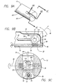
- FIGS. 9a, 9b, and 9c depict the distal end portion 26 of an endoscope similar to that in FIG. 3.
- FIG. 9b depicts the distal end portion 26 in partial cross-section along the line 9B-9B depicted in FIG. 9a, while FIG 9c depicts a partial cross-section along the line 9C-9C.
- the second reflector 32 is secured within a rotatable housing 106 that includes a small side opening 108 that allows light to pass between the second reflector 32 and the first reflector 30.
- a viewing opening 110 allows light to pass between the second reflector and the window 34.
- the window 34 is large enough to cover the entire "sweep" angle through which the second reflector 32 can view, with the window 34 serving to allow light to pass while sealing the entire assembly against outside contamination. Such sealing can make the device easier to sterilize.
- the housing 106 is rotatably mounted to permit rotation with the second reflector 32 about the second reflector's rotational axis 48.
- the second reflector is mounted in a rotatable housing that is configured so that it can be positioned on the outside of the endoscope shaft.
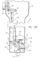
- a rotatable housing 112 containing the second reflector 32 can be moved from inside the endoscope shaft 23 to the outside of the endoscope shaft 23.
- the housing 112 In the extended position depicted in FIG. 10a, the housing 112 is positioned on the outside of the endoscope main shaft 23.
- the window 34 is located directly on the rotatable housing 112, so that the window 34 rotates with the second reflector 32.
- the rotational housing 112, and therefore the second reflector 32 can be rotated 360 degrees about an axis 48 perpendicular to the longitudinal axis 27 of the endoscope 12.
- a 360 degree rotation of the second reflector 32 is combined with a 360 degree rotation of the endoscope main shaft 23 about its longitudinal axis 27, complete spherical viewing of the body cavity can be achieved.
- the housing 112 can be retracted into the endoscope shaft 23, which may facilitate the endoscope's insertion into and removal from the cavity being viewed.
- Various devices can be used to retract and deploy the housing 112.
- the housing 112 is biased toward the retracted position by a spring 114 that urges the gear shaft 54, and hence the housing 112, away from an opening 116 in the endoscope shaft 23.
- Extending the housing 112 out of the shaft 23 is achieved by an electromagnet 118 that, when activated by sufficient voltage to overcome the resistance of the spring 114, urges an opposite movement of the gear shaft 54 so as to cause the housing 112 to assume the extended position depicted in FIG. 10a.
- the spring 114 is constantly urging the housing 112 to the retracted position of FIG. 10b, an accidental or intentional interruption of power to the electromagnet 118 will cause the housing 112 to retract.
- the spring 114 and electromagnet 118 are secured to the shaft so as to permit the gear shaft 54 to freely rotate about its axis.
- the retracted housing 112 is sized to assist, in both the retracted and expanded positions, in maintaining a seal about the opening 116 in the endoscope shaft 23, thereby preventing the admission of contaminants into the endoscope shaft 23.
- the fiber-optic bundle 80 of the first optical path portion 42, and the illumination line 78 are positioned within the hollow gear shaft 54.
- the alignment of the gear shaft 54 and fiber-optic bundle 80 appears to be offset in FIGS 10a and 10b between the endoscope distal portion 26 and the endoscope proximal portion 24, they are in fact aligned.
- the apparent misalignment is caused by the "break" in the each figure between the ends of the endoscope, and is further exaggerated by the endoscope length being much larger as compared to the endoscope width.
- an irrigation channel can be positioned so as to provide a fluid flow that passes over the window.
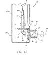
- an irrigation channel opening 124 is positioned so that the fluid flow passes along the surface of the window 34, thereby washing debris off of the window 34.
- the irrigation channel opening 124 is positioned so that, when the housing 112 is rotated to a certain position, an irrigation flow passes over the window 34.
- a user can clean the window 34 by rotating the housing 112 into a position adjacent the irrigation channel 124.
- FIG. 13 Other embodiments (such as FIG. 1) of the invention have a monitor positioned apart from the endoscope, but a monitor may be positioned on the endoscope itself.
- the endoscope 12 includes a monitor 14 secured to the proximal portion of the endoscope 12.
- the monitor 14 is relatively small, and is positioned to generally mimic the position of an eyepiece on a conventional endoscope.
- a user who is accustomed to conventional endoscopes equipped with eyepieces may be more comfortable using the endoscope-mounted monitor 14 than he or she would be viewing a surgical procedure on a large monitor separate from the endoscope.
- the endoscope-mounted monitor 14 may thus be used in lieu of, or in addition to, an external monitor such as the one depicted in FIG. 1.
- FIG. 14 depicts another embodiment of the invention, wherein an endoscopic system 126 includes an endoscope 12 with a camera 38 rigidly mounted to the endoscope 12, as opposed to the rotational mounting depicted in other embodiments.
- the system 126 of FIG. 14 includes a processor 128 that receives the image signals from the camera 38, and then processes the signals to compensate for the rotation of the second reflector.
- the processing of the signals includes: (1) receiving a position signal from the endoscope 12 indicating the rotational position of the second reflector; (2) "rotating" the image from the camera 38 by an angle corresponding to the angle of rotation of the second reflector; and (3) providing a rotated image to the monitor 14, with the rotation of the image corresponding to the rotation of the second reflector.
- a rotation of the image can be achieved through relatively simple processing.
Landscapes
- Health & Medical Sciences (AREA)
- Life Sciences & Earth Sciences (AREA)
- Surgery (AREA)
- Biomedical Technology (AREA)
- Medical Informatics (AREA)
- Optics & Photonics (AREA)
- Pathology (AREA)
- Radiology & Medical Imaging (AREA)
- Biophysics (AREA)
- Engineering & Computer Science (AREA)
- Physics & Mathematics (AREA)
- Heart & Thoracic Surgery (AREA)
- Nuclear Medicine, Radiotherapy & Molecular Imaging (AREA)
- Molecular Biology (AREA)
- Animal Behavior & Ethology (AREA)
- General Health & Medical Sciences (AREA)
- Public Health (AREA)
- Veterinary Medicine (AREA)
- Instruments For Viewing The Inside Of Hollow Bodies (AREA)
- Endoscopes (AREA)
Abstract
Description
- This invention relates generally to viewing systems and, more particularly, to an apparatus for providing spherical viewing in a cavity, such as an internal body cavity of a patient.
- Minimally invasive surgery (MIS) such as laparoscopic, endoscopic, hysteroscopic, and arthroscopic surgery (referred to hereafter generally as endoscopic surgery), is becoming more widely used because it is often less traumatic to the patient, generally involves less hospitalization time, less discomfort, and less risk to the patient, and is usually less costly than traditional open surgery.
- The endoscopic surgery is generally preformed using elongate instruments slidably inserted through an opening into a body cavity. If the body cavity is accessible through a naturally occurring body orifice, the instruments may be inserted through that orifice. In cases where the body cavity is otherwise inaccessible, a small incision may be created in the patient to provide access to the area to be treated. A trocar sheath may be inserted in the incision, with the trocar sheath configured to permit the slidable insertion and rotation of endoscopes and surgical instruments into the cavity.
- An endoscope is generally used to view the inside of the body cavity. For example, an endoscope can be used to inspect the condition of the tissue lining a body organ, such as a human uterus. The endoscope can also be used to observe the manipulations being performed by surgical instruments positioned within the body cavity. Most current endoscopes provide a limited and fixed view, so that the surgeon typically must physically reposition the entire endoscope in order to change the endoscopic view within the body cavity, or remove the endoscope entirely and replace it with one having the desired angle of view. Such manipulations and replacements can be undesirable, since they can complicate the surgery and increase the risk of inadvertent damage to body tissue from accidental contact between the tissue and the endoscope.
- Several previous designs have been proposed to permit individual endoscopes to very their angles of view without requiring extensive movement of the endoscope. The small sizes of endoscope, which can be on the order of 3 mm in diameter, place restrictions on such designs, and limit the options available. For example, complicated combinations of optics may be difficult to assemble in the small enclosure provided by the body of many endoscopes.
- EP-A-0251478 discloses an apparatus that uses a pair of Schmidt prisms in adjusting the viewable image when a viewing angle is changed, the image being viewable through a fixed eyepiece.
- Therefore, those concerned with the development and use of endoscopic surgical systems and the like have long recognized the need for a system which is capable of enabling a surgeon to efficiently view large portions of internal cavities without requiring large manipulations or replacements of endoscopes during a procedure. Accordingly, the present invention fulfils these needs by providing an efficient and effective endoscope apparatus, selectively operable to permit a surgeon to view the majority of the internal area without having to replace or make major movements of the endoscope.
- Briefly, the present invention is defined in the independent claims.
- The present invention provides an endoscope or similar viewing apparatus that permits near-spherical viewing of a cavity, such as an internal enclosure, a crevass, or other generally inaccessible area. The invention permits such viewing without requiring large movements of the endoscope. The apparatus includes a distal portion with distal viewing optics, such as reflectors or cameras, that collect images from the cavity interior. The images are then relayed to the proximal portion of the apparatus, where they can be viewed by a user or relayed to an external display.
- By moving an internal reflector within the distal portion of the endoscope, the endoscope can vary its angle of view from 0 degrees (i.e., straight ahead from the endoscope distal end) to as much as plus or minus 180 degrees (i.e., looking back toward the proximal portion of the endoscope), depending on the particular design. Rotation of the endoscope distal viewing optics about the endoscope's longitudinal axis, such as may be accomplished by rotating the entire endoscope about its longitudinal axis, when combined with the previously discussed angle-varying optical procedure, permits the endoscope to achieve near-spherical viewing of the interior of the body cavity, without requiring the endoscope to undertake any movement except a simple rotation about its longitudinal axis. Moreover, where the endoscope is surrounded by or otherwise includes an outer sheath that remains stationary during such rotations, the movement of the interior portions of the endoscope (to permit spherical viewing) can be conducted with the outer sheath remaining stationary, thus preventing any potential damage to tissue that may be in contact with the outer sheath.
- The invention further provides improved feedback to the user regarding the line of sight along which the system is viewing. The feedback may be provided on a monitor or via directional control mechanisms, such as a rotator knob positioned on the endoscope.
- These and other features of the invention will become apparent from the following detailed description, when taken in conjunction with the accompanying drawings.
-
- FIGURE 1 is a view of an endoscopic viewing system according to an embodiment of the invention;
- FIG. 2 is a perspective view of an endoscope according to an embodiment of the invention;
- FIG. 3 is a cross-sectional side view of the endoscope depicted in FIG.2, according to an embodiment of the invention;
- FIG. 4a is a perspective view of a proximal portion of an endoscope in accordance with an embodiment of the invention;
- FIG. 4b is a perspective view of a proximal portion of an endoscope in accordance with an embodiment of the invention;
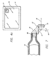
- FIG. 4c is a front view of a video monitor in accordance with an embodiment of the invention;
- FIG. 5 is a cross-sectional side view of an endoscope, according to an embodiment of the invention;
- FIG. 6 is a cross-sectional side view of an endoscope, according to an embodiment of the invention;
- FIG. 7 is a cross-sectional side view of a distal portion of an endoscope, according to an embodiment of the invention;
- FIG. 8 is a cross-sectional side view of a distal portion of an endoscope, according to an embodiment of the invention;
- FIG. 9a is a perspective view of a distal portion of an endoscope, according to an embodiment of the invention;
- FIGS. 9b and 9c are cross-sectional views of the endoscope depicted in FIG. 9a;
- FIGS. 10a and 10b are cross-sectional side views of an endoscope, according to an embodiment of the invention;
- FIG. 11 is a perspective view of an endoscope, according to an embodiment of the invention;
- FIG. 12 is a cross-sectional side view of a distal end portion of an endoscope, according to an embodiment of the invention;
- FIG. 13 is a side view, in partial cross-section, of an endoscope, according to an embodiment of the invention;
- FIG. 14 is a view of an endoscopic viewing system according to an embodiment of the invention; and.
-
- Referring now to the drawings with more particularity, wherein like reference numerals in the separate views indicate like or corresponding elements, there is shown in FIG. 1 a
system 10 for endoscopic viewing. Theendoscopic system 10 includes anendoscope 12, amonitor 14 for viewing images received from theendoscope 12, and anillumination source 16 for providing illumination to the area being viewed by theendoscope 12. - In typical usage, the
endoscope 12 is inserted into acavity 18 or other area to be viewed, such as a human body cavity. The endoscope receives illumination from theillumination source 16, with the illumination passing through a light-transmittingcable 20, such as a fiber-optic cable or the like, to theendoscope 12 and into thecavity 18 to illuminate desired portions of the cavity. - Although the embodiment depicted in FIG. 1 has the
illumination source 16 outside of theendoscope 12, the illumination source may be positioned on or within the endoscope itself. For example, a small light source, such as an LED or small light bulb, may be positioned on or within the endoscope in a position that permits the light to travel, either directly or through reflectors or fiber-optic cables and the like, to shine on desired portions of the cavity. - In FIG. 1, the
monitor 14 receives image signals from theendoscope 12. In the embodiment depicted, the images are transmitted to themonitor 14 via one ormore cables 22 passing from theendoscope 12 to themonitor 14. - FIGS. 2 and 3 show in greater detail an embodiment of an endoscope in accordance with the invention. As depicted in FIGS. 2 and 3, the
endoscope 12 has a generallytubular shaft 23, with an enlargedproximal end portion 24 and adistal end portion 26. In use, the user can grasp theendoscope 12 by itsproximal end portion 24 and insert thedistal end portion 26 into thecavity 18. Theendoscope 12 can be rotated about itslongitudinal axis 27 to provide some control of the viewing direction. - The
distal end portion 26 includes anoptical assembly 28 positioned inside. Theoptical assembly 28 comprises afirst reflector 30 and asecond reflector 32, which in the embodiment depicted are both prisms. Thedistal end portion 26 includes awindow 34 through which the second reflector receives light (and images) from the outside of theendoscope 12. In the embodiment of FIGS. 2 and 3, thewindow 34 comprises a clear layer of material that seals the endoscope against fluids and other debris while admitting light for viewing the interior of the body cavity. Such a lens may be formed of various materials, such as plastic, glass, or other materials, depending on the desired application. In other embodiments, the window may simply comprise an unobstructed opening in thedistal end portion 26 of theendoscope 12. - The
first reflector 30 andsecond reflector 32 are positioned in the endoscope so as to define anoptical path 36 passing from outside of the endoscope 12 (i.e., from inside the body cavity), through thewindow 34, to thesecond reflector 32, to thefirst reflector 30, and then to aCCD camera 38 positioned in theproximal end portion 24 of theendoscope 12. In the embodiment depicted in FIG. 3, arod lens 40 transmits light between thefirst reflector 30 and thecamera 38, so that theoptical path 36 passes along therod lens 40. Theoptical path 36 is thus broken into three portions. The firstoptical path portion 42 passes from thecamera 38 to thefirst reflector 30; the secondoptical path portion 44 passes from thefirst reflector 30 to thesecond reflector 32; and the thirdoptical path portion 46 passes from thesecond reflector 32 out through thewindow 34.Various lenses 47 are positioned along theoptical path 36 to help concentrate and focus images. - In the embodiment of FIG. 3, the
first reflector 30 is rigidly secured to the interior of theendoscope 12, while thesecond reflector 32 is rotatably mounted in theendoscope 12 to permit thesecond reflector 32 to be rotated about anaxis 48 generally aligned with the secondoptical path portion 44 adjacent to thesecond reflector 32. Rotation of thesecond reflector 32 about itsaxis 48 does not move or otherwise disrupt the secondoptical path portion 44, but that rotation does cause the thirdoptical path portion 46 to "sweep" through viewing angles equivalent to the angular rotation of thesecond reflector 32. Thus, thecamera 38 is provided with images from the viewing angles swept through by the third optical path portion. For example, a 30 degree rotation of thesecond reflector 32 will cause the camera to receive images corresponding to a 30 degree sweep of the third optical path. - Various techniques may be employed to control rotation of the second reflector. A small actuator motor may be used, such as one positioned at the distal end portion of the endoscope to rotate the second reflector in response to signals received from a user. The second reflector may be rotated by mechanical means, such as a system of actuator motors, pull lines or wires, and/or a gearing system such as that depicted in FIG. 3. Other control techniques could also be used without departing from the scope of the invention.
- In order to control the rotation of the
second reflector 32, the embodiment of FIG. 3 includes a gearing system that includes asecond reflector gear 50 to which thesecond reflector 32 is secured. Thesecond reflector gear 50, which rotates about thesecond reflector axis 48, is meshed to adistal gear 52 secured to agear shaft 54 that passes generally along the length of theendoscope shaft 23. Secured to the proximal end of thegear shaft 54 is aproximal gear 56, which in the embodiment depicted is a spur wheel gear. Theproximal gear 56 is meshed to arotator control gear 58, which in the embodiment shown is a crown gear. The rotator control gear is secured to arotator control knob 60. - A person skilled in the optical arts will note that rotation of the
second reflector 32 about itsrotational axis 48 will cause the image received by thecamera 38 to rotate in a manner that can be awkward for a user to view and comprehend. To compensate for this effect, the invention in the embodiment of FIG. 3 has thecamera 38 rotatably secured to theendoscope shaft 23 to permit its rotation about anaxis 62 generally aligned with the firstoptical path portion 42 adjacent to thecamera 38. Rotation of thecamera 38 is controlled to correspond to rotation of thesecond reflector 32. In the embodiment depicted in Fig. 3, the camera is secured to acamera gear 64, which is depicted as a spur wheel gear, having anaxis 62 aligned with the firstoptical path portion 42 adjacent to thecamera 38. Thecamera gear 64 is meshed to theproximal gear 56 of thegear shaft 54. In the embodiment shown, the gearing assembly is engineered such that inducing rotation of thesecond reflector 32 causes an equivalent amount of rotation of thecamera 38. For example, rotating thesecond reflector 32 by 90 degrees will cause thecamera 38 to rotate by 90 degrees, i.e., a one-to-one ratio between the corresponding rotations of thecamera 38 andsecond reflector 32. Other corresponding rotation ratios between the camera and second reflector may also be used, depending on a particular apparatus. - An important issue for endoscopes is the ability of the user to determine in which direction the endoscope is "looking." Failure to know precisely the direction in which the endoscope is looking can complicate a procedure. Accordingly, it is preferred that the user have a reference indicating the viewing position of the endoscope.
- The rotator controller of the current invention can serve the function of indicating the viewing angle of the endoscope. In the embodiment depicted in FIGS. 2 and 3, the
rotator controller knob 60 is configured to indicate the viewing angle of theendoscope 12. Therotator knob 60 is rotatably secured to theproximal end portion 24 of theendoscope 12, with the rotator knobrotational axis 66 parallel to the second reflectorrotational axis 48. Moreover, the gearing assembly between therotator knob 60 andsecond reflector 32 is configured such that rotation of therotator knob 60 causes an equivalent rotation (i.e., a one-to-one corresponding rotation) of the second reflector. For example, a ninety-degree rotation of therotator knob 60 will cause a ninety-degree rotation of thesecond reflector 32. - To further assist the user in determining the viewing angle, the
rotator knob 60 may include markings or other indicia that show the viewing angle of theendoscope 12. For example, in the embodiment depicted in Fig. 2, therotator knob 60 includes a marking 68 indicating the rotational position of theknob 60, which, in the case where therotator knob 60 andsecond reflector 32 have corresponding rotations, also serves to indicate the rotational position of thesecond reflector 32, thus depicting the viewing angle of theendoscope 12. - During a surgical procedure, a user may be keeping his or her eyes on the video monitor receiving images from the camera. Thus, the user may not have much opportunity to actually look at the position of the rotator knob. Accordingly, the positional markings on the rotator knob may include surface indicators that can be easily detected by touch, such as variances in surface texture or form. These may include raised, lowered, or roughened surfaces. Thus, the user can know the position of the knob, and hence the viewing angle, by merely touching the knob, without necessarily having to take his or her eyes off of the monitor to actually see the knob.
- In the embodiment of Fig. 2, the marking 68 is a raised arrow, with the arrow aligned to be parallel with the third
optical path portion 46 passing from thesecond reflector 32 out of theviewing window 34. Thus, the arrow's rotational position indicates the actual viewing angle of theendoscope 12. - The indicia may comprise a series of one or more raised portions on the
rotator knob 60, such as one or more raised dots. For example, in the embodiment of FIG. 4a, the indicia is a combination of a central raiseddot 70 with a series of outer raiseddots pointer 75 extending from therotator knob 60. Like the raised arrow of Fig. 3, the central raiseddot 70 and outer raiseddots pointer 75 of FIG. 4b are aligned so as to be parallel to the thirdoptical path portion 46 passing from thesecond reflector 32 out of theviewing window 34. Thus, the raiseddots pointer 75 indicate the line of sight of theendoscope 12. - In a further embodiment, an outside display may indicate the viewing angle of the endoscope, such as where the endoscope provides a signal to a monitor to represent the viewing angle. For example, the rotator knob may include sensors or other devices that provide rotational position signals to a video monitor, with the video monitor providing a numerical, graphical, or other representation of the viewing angle. In the embodiment depicted in FIG. 4c, the
monitor 14 that provides images of the interior of the cavity on itsmain screen 76 also depicts agraphical representation 77 of the viewing angle. - In the embodiment of FIGS. 1-3, illumination is provided by an
external illumination source 16 that provides light through a light-transmittingcable 20. Thelight transmitting cable 20 connects to one ormore illumination fibers 78 that pass alongside therod lens 40 and transmit the light to thefirst reflector 30, where the light is reflected off of thefirst reflector 30, to thesecond reflector 32, and then out of thewindow 34 to thecavity 18. - In the embodiment depicted in FIG. 3, the
optical path portions optical path 36 and itsportions optical path portions optical path portion 42, i:e., the portion between thecamera 38 and thefirst reflector 30, includes a flexible fiber-optic bundle 80 with anobjective lens 81 at either end. The flexible fiber-optic bundle 80 permits theshaft 23 of theendoscope 12 to be curved or bent without causing a break in theoptical path 36, as may be necessary for theshaft 23 to pass through tortuous curves in a body passage. Such a feature could permit construction of a rigid but non-straight (e.g., curved) endoscope shaft, or even of a flexible endoscope shaft. - FIGS. 6 through 8 depict additional embodiments of the invention, with variations to the optical assemblies. In FIG. 6, a rod
lens relay system 82 is positioned along the firstoptical path portion 42, with therod lens system 82 including a series ofsmall rod lenses 84 aligned along the firstoptical path portion 42. Various objective lenses 86 are used to concentrate and focus the images along the optical path. - The first and second reflectors themselves may be varied within the scope of the invention. For example, the prisms depicted in the various embodiments may be replaced with mirrors or other reflective and/or refractive devices without departing from the scope of the invention. Note that the term "reflector" is, in the terms of this application, considered to encompass any device that diverts the passage of light. Additionally, various optical assemblies, such as filters and/or objective lenses, may be positioned in the optical path to enhance the images received by the camera. For example, FIG. 7 depicts two objective lenses, with a positive
objective lens 88 positioned against thefirst reflector 30 along the firstoptical path portion 42, and a negativeobjective lens 90 positioned against thesecond reflector 32 along the thirdoptical path portion 46. FIG. 7 further includes aspacer 92 that may be employed to maintain the spacing between thefirst reflector 30 andsecond reflector 32. Thespacer 92 thus serves to assist in securing the reflectors in their desired positions, which can prevent damage to the reflectors if the endoscope is dropped or otherwise roughly handled. Thespacer 92 may be formed from a lubricious material that seals the adjacent reflector surfaces from contamination while permitting thesecond reflector 32 to freely rotate. - Returning to FIG. 3, the
gear shaft 54 is hollow, defining achannel 94 therein. Thechannel 94 passes from the outside of theproximal end portion 24 and terminates at anopening 96 in thedistal end portion 26 of theendoscope 12. In the embodiment of FIG. 3, an O-ring 98 is positioned at the distal end of thegear shaft 54 so as to have thechannel 94 open to the body cavity while maintaining a seal of other portions of theendoscope 12. Accordingly, thechannel 94 may, depending on its size, be used as an irrigation channel for the introduction and/or removal of irrigating fluids to the cavity. Thechannel 94 may also serve as an access channel for the introduction of tools, such as surgical tools, to the cavity. - In other embodiments of the invention, several channels may be provided in the endoscope, including separate channels for fluid introduction, fluid removal, and instrument introduction. For example, in the embodiment of FIG. 8, three separate channels are provided in the
distal end portion 26 of anendoscope 12. Anirrigation channel 100 serves to introduce fluids into the cavity, while a separatefluid removal channel 102 can simultaneously remove fluids. A largerinstrument introduction channel 104 permits surgical tools to be introduced into the cavity. - Various embodiments of the endoscope
distal end portion 26 are within the scope of the invention. In the embodiment depicted in FIG. 3, thewindow 34 comprises a fixed transparent cover that seals the endoscope, thereby protecting the optical assembly within, including thefirst reflector 30 andsecond reflector 32. FIGS. 9a, 9b, and 9c depict thedistal end portion 26 of an endoscope similar to that in FIG. 3. FIG. 9b depicts thedistal end portion 26 in partial cross-section along theline 9B-9B depicted in FIG. 9a, while FIG 9c depicts a partial cross-section along theline 9C-9C. In the embodiment depicted, thesecond reflector 32 is secured within arotatable housing 106 that includes asmall side opening 108 that allows light to pass between thesecond reflector 32 and thefirst reflector 30. Aviewing opening 110 allows light to pass between the second reflector and thewindow 34. Thewindow 34 is large enough to cover the entire "sweep" angle through which thesecond reflector 32 can view, with thewindow 34 serving to allow light to pass while sealing the entire assembly against outside contamination. Such sealing can make the device easier to sterilize. Thehousing 106 is rotatably mounted to permit rotation with thesecond reflector 32 about the second reflector'srotational axis 48. - In another embodiment, the second reflector is mounted in a rotatable housing that is configured so that it can be positioned on the outside of the endoscope shaft. For example, in the embodiment shown in FIGS. 10a and 10b, a
rotatable housing 112 containing thesecond reflector 32 can be moved from inside theendoscope shaft 23 to the outside of theendoscope shaft 23. In the extended position depicted in FIG. 10a, thehousing 112 is positioned on the outside of the endoscopemain shaft 23. Thewindow 34 is located directly on therotatable housing 112, so that thewindow 34 rotates with thesecond reflector 32. By positioning therotational housing 112 of FIG. 10a on an external portion of theendoscope shaft 23, therotational housing 112, and therefore thesecond reflector 32, can be rotated 360 degrees about anaxis 48 perpendicular to thelongitudinal axis 27 of theendoscope 12. When such a 360 degree rotation of thesecond reflector 32 is combined with a 360 degree rotation of the endoscopemain shaft 23 about itslongitudinal axis 27, complete spherical viewing of the body cavity can be achieved. - As depicted in FIG. 10b, the
housing 112 can be retracted into theendoscope shaft 23, which may facilitate the endoscope's insertion into and removal from the cavity being viewed. Various devices can be used to retract and deploy thehousing 112. In the embodiment depicted in FIG. 10b, thehousing 112 is biased toward the retracted position by aspring 114 that urges thegear shaft 54, and hence thehousing 112, away from anopening 116 in theendoscope shaft 23. Extending thehousing 112 out of theshaft 23 is achieved by anelectromagnet 118 that, when activated by sufficient voltage to overcome the resistance of thespring 114, urges an opposite movement of thegear shaft 54 so as to cause thehousing 112 to assume the extended position depicted in FIG. 10a. Because thespring 114 is constantly urging thehousing 112 to the retracted position of FIG. 10b, an accidental or intentional interruption of power to theelectromagnet 118 will cause thehousing 112 to retract. Note that, in the embodiment of FIGS. 10a and 10b, thespring 114 andelectromagnet 118 are secured to the shaft so as to permit thegear shaft 54 to freely rotate about its axis. In the embodiment depicted, the retractedhousing 112 is sized to assist, in both the retracted and expanded positions, in maintaining a seal about theopening 116 in theendoscope shaft 23, thereby preventing the admission of contaminants into theendoscope shaft 23. - Also in FIGS. 10a and 10b, the fiber-
optic bundle 80 of the firstoptical path portion 42, and theillumination line 78, are positioned within thehollow gear shaft 54. Although the alignment of thegear shaft 54 and fiber-optic bundle 80 appears to be offset in FIGS 10a and 10b between the endoscopedistal portion 26 and the endoscopeproximal portion 24, they are in fact aligned. The apparent misalignment is caused by the "break" in the each figure between the ends of the endoscope, and is further exaggerated by the endoscope length being much larger as compared to the endoscope width. - In order to keep a viewing window formed of solid material (as opposed to an open window) clean of debris, an irrigation channel can be positioned so as to provide a fluid flow that passes over the window. For example, in FIG. 11, which is similar to the embodiment of FIG. 3, an
irrigation channel opening 124 is positioned so that the fluid flow passes along the surface of thewindow 34, thereby washing debris off of thewindow 34. In FIG. 12, which is similar to the embodiment of FIG. 10, theirrigation channel opening 124 is positioned so that, when thehousing 112 is rotated to a certain position, an irrigation flow passes over thewindow 34. Thus, a user can clean thewindow 34 by rotating thehousing 112 into a position adjacent theirrigation channel 124. - Other embodiments (such as FIG. 1) of the invention have a monitor positioned apart from the endoscope, but a monitor may be positioned on the endoscope itself. For example, in the embodiment depicted in FIG. 13, the
endoscope 12 includes amonitor 14 secured to the proximal portion of theendoscope 12. Themonitor 14 is relatively small, and is positioned to generally mimic the position of an eyepiece on a conventional endoscope. Thus, a user who is accustomed to conventional endoscopes equipped with eyepieces may be more comfortable using the endoscope-mountedmonitor 14 than he or she would be viewing a surgical procedure on a large monitor separate from the endoscope. The endoscope-mountedmonitor 14 may thus be used in lieu of, or in addition to, an external monitor such as the one depicted in FIG. 1. - FIG. 14 depicts another embodiment of the invention, wherein an
endoscopic system 126 includes anendoscope 12 with acamera 38 rigidly mounted to theendoscope 12, as opposed to the rotational mounting depicted in other embodiments. To correct for undesirable viewing problems caused by rotation of the second reflector, thesystem 126 of FIG. 14 includes aprocessor 128 that receives the image signals from thecamera 38, and then processes the signals to compensate for the rotation of the second reflector. The processing of the signals includes: (1) receiving a position signal from theendoscope 12 indicating the rotational position of the second reflector; (2) "rotating" the image from thecamera 38 by an angle corresponding to the angle of rotation of the second reflector; and (3) providing a rotated image to themonitor 14, with the rotation of the image corresponding to the rotation of the second reflector. Such a rotation of the image can be achieved through relatively simple processing.
Claims (11)
- An apparatus for examining the interior of a cavity (10), comprising:a generally tubular member (23) having a distal end portion (26) and a promixal end portion (24);a camera (38) rotatably secured to the tubular member (23);a first reflector (30) positioned in the distal end portion (26) of the tubular member (23);a second reflector (32) rotatably positioned in the distal end portion (26) of the tubular member (23), said second reflector (32) positioned so as to be optically aligned with the camera (38) through the first reflector (30), whereby an optical path (36) is defined between the camera (38), the first reflector (30), and the second reflector (32), and whereby the optical path (36) comprises a first optical path portion (42) passing between the camera (38) and the first reflector (30), and a second optical path portion (44) passing between the first reflector (30) and the second reflector (32);a viewing window (34) positioned at the distal end portion of the tubular member (23), said viewing window (34) positioned so as to be optically aligned with the camera (38) and the first reflector (30) through the second reflector (32), whereby the optical path (36) further comprises a third optical path portion (46) passing between the second reflector (32) and the viewing window (34);a rotator (60) for selectively rotating the second reflector (32) about an axis (48) generally aligned with the second optical path portion (44), and for selectively rotating the camera (38) about an axis (62) generally aligned with the first optical path portion (42).
- The apparatus of claim 1, wherein the rotator (60) controls rotation of the camera (38) and the second reflector (32) to cause corresponding rotations of the camera (38) and of the second reflector (32).
- The apparatus of claim 2, wherein the rotator (60) controls rotation of the camera (38) and the second reflector (32) cause equivalent rotations of the camera (38) and of the second reflector (32).
- The apparatus of claim 3, further comprising:a television monitor (14) for receiving image signals from the camera (38) and for providing a display based on the received image signals.
- The apparatus of claim 1, wherein the apparatus further comprises:an opening (96, 124) in the distal end portion (26) of the tubular member (23); anda channel (94) passing from the tubular member proximal end portion (24) to the tubular member distal end opening (96, 124).
- The apparatus of claim 5, wherein the channel (94) comprises an irrigation channel for providing an irrigating fluid.
- The apparatus of claim 6, wherein the distal end opening (124) provides a stream of irrigating fluid, and the distal end opening (124) is positioned so as to cause the irrigating fluid stream to pass over the viewing window (34), whereby the irrigating fluid stream removes debris from the viewing window (34).
- The apparatus of claim 1 for providing an irrigation fluid, wherein the rotator comprises:a gear shaft (54) passing generally parallel to a central axis of the tubular member (23), said gear shaft (54) having a proximal end portion and a distal end portion;a distal gear (52) secured to the distal end portion of the gear shaft (54), said distal gear (52) having an axis of rotation in general alignment with the gear shaft (54);a reflector gear (50) mechanically meshed with the distal gear (52), said reflector gear (50) being rigidly secured to the second reflector (32), said reflector gear (50) having an axis of rotation in axial alignment with the axis of rotation (48) of the second reflector, said reflector gear (50) mechanically linked with the distal gear (52), whereby rotation of the gear shaft (54) and distal gear (52) causes a corresponding rotation of the reflector gear (50) and second reflector (32).
- The apparatus of claim 8, further comprising:wherein the gear shaft channel (94) is aligned with the distal opening (96, 124) of the tubular member, thereby defining an open channel passing from the distal opening (96, 124) to the gear shaft proximal end portion.a distal opening (96, 124) in the distal end portion (26) of the tubular member (23); anda channel (94) passing through the gear shaft (54) from the gear shaft proximal end portion to the gear shaft distal end portion; and
- The apparatus of claim 9, wherein the open channel comprises an irrigation channel for providing an irrigating fluid.
- An apparatus for examining the interior of a cavity, comprising:a generally tubular member (23) having a distal end portion and a proximal end portion;a camera (38) secured to the tubular member, said camera for providing an image;a first reflector positioned in the distal end portion of the tubular member;a second reflector rotatably positioned in the distal end portion of the tubular member, said second reflector positioned so as to be optically aligned with the camera through the first reflector, whereby an optical path is defined between the camera, the first reflector, and the second reflector, and whereby the optical path comprises a first optical path portion passing between the camera and the first reflector, and a second optical path portion passing between the first reflector and the second reflector;a viewing window positioned at the distal end portion of the tubular member, said viewing window positioned so as to be optically aligned with the camera and the first reflector through the second reflector, whereby the optical path further comprises a third optical path portion passing between the second reflector and the viewing window, with said third optical path portion generally aligned with a viewing angle of the apparatus;a rotator(60) for selectively rotating the second reflector about an axis generally aligned with the second optical path portion;a processor (128) configured (a) to receive the image from the camera, (b) receive a rotational signal, (c) rotate the received image as a function of the rotational signal, and (d) provide a rotated image; anda monitor (14) to display the rotated image, wherein the monitor is configured to display a representation of the viewing angle.
Applications Claiming Priority (5)
| Application Number | Priority Date | Filing Date | Title |
|---|---|---|---|
| US7637798P | 1998-02-19 | 1998-02-19 | |
| US76377P | 1998-02-19 | ||
| US8178098P | 1998-04-14 | 1998-04-14 | |
| US81780P | 1998-04-14 | ||
| PCT/US1999/003656 WO1999042028A1 (en) | 1998-02-19 | 1999-02-19 | Apparatus and method for providing spherical viewing during endoscopic procedures |
Publications (2)
| Publication Number | Publication Date |
|---|---|
| EP1056388A1 EP1056388A1 (en) | 2000-12-06 |
| EP1056388B1 true EP1056388B1 (en) | 2004-12-22 |
Family
ID=26758035
Family Applications (1)
| Application Number | Title | Priority Date | Filing Date |
|---|---|---|---|
| EP99908281A Expired - Lifetime EP1056388B1 (en) | 1998-02-19 | 1999-02-19 | Apparatus for providing spherical viewing during endoscopic procedures |
Country Status (6)
| Country | Link |
|---|---|
| US (1) | US6371909B1 (en) |
| EP (1) | EP1056388B1 (en) |
| AU (1) | AU2775199A (en) |
| CA (1) | CA2321488C (en) |
| DE (1) | DE69922791T2 (en) |
| WO (1) | WO1999042028A1 (en) |
Cited By (1)
| Publication number | Priority date | Publication date | Assignee | Title |
|---|---|---|---|---|
| DE102011007484A1 (en) * | 2011-04-15 | 2012-10-18 | Henke-Sass, Wolf Gmbh | Endoscope with variable viewing direction |
Families Citing this family (260)
| Publication number | Priority date | Publication date | Assignee | Title |
|---|---|---|---|---|
| US6629630B2 (en) * | 1998-06-19 | 2003-10-07 | Scimed Life Systems, Inc. | Non-circular resection device and endoscope |
| US8944070B2 (en) | 1999-04-07 | 2015-02-03 | Intuitive Surgical Operations, Inc. | Non-force reflecting method for providing tool force information to a user of a telesurgical system |
| NL1012790C2 (en) * | 1999-08-06 | 2001-02-07 | Univ Delft Tech | Endoscope. |
| GB2354836B (en) | 1999-09-28 | 2003-06-04 | Keymed | Improvements relating to borescopes and endoscopes with variable direction of view |
| US6364830B1 (en) | 1999-11-30 | 2002-04-02 | Durell & Gitelis, Inc. | Variable view arthroscope |
| US7039453B2 (en) * | 2000-02-08 | 2006-05-02 | Tarun Mullick | Miniature ingestible capsule |
| JP3345645B2 (en) | 2000-06-20 | 2002-11-18 | 東京大学長 | Body cavity observation device |
| JP3857864B2 (en) * | 2000-08-01 | 2006-12-13 | フジノン株式会社 | Endoscopic linear transmission member driving apparatus |
| US6929603B2 (en) | 2000-08-30 | 2005-08-16 | Durell & Gitelis, Inc. | Variable view arthroscope |
| US6638216B1 (en) | 2000-08-30 | 2003-10-28 | Durell & Gitelis, Inc. | Variable view arthroscope |
| US7175593B2 (en) | 2000-08-30 | 2007-02-13 | Durell & Gitelis, Inc. | Variable view arthroscope with charge coupled device |
| JP3782927B2 (en) * | 2000-09-04 | 2006-06-07 | フジノン株式会社 | Endoscopic linear transmission member driving apparatus |
| US6695774B2 (en) | 2001-01-19 | 2004-02-24 | Endactive, Inc. | Apparatus and method for controlling endoscopic instruments |
| US6916286B2 (en) * | 2001-08-09 | 2005-07-12 | Smith & Nephew, Inc. | Endoscope with imaging probe |
| US6921920B2 (en) * | 2001-08-31 | 2005-07-26 | Smith & Nephew, Inc. | Solid-state light source |
| US6692431B2 (en) * | 2001-09-07 | 2004-02-17 | Smith & Nephew, Inc. | Endoscopic system with a solid-state light source |
| US10285694B2 (en) | 2001-10-20 | 2019-05-14 | Covidien Lp | Surgical stapler with timer and feedback display |
| US7464847B2 (en) | 2005-06-03 | 2008-12-16 | Tyco Healthcare Group Lp | Surgical stapler with timer and feedback display |
| US6648817B2 (en) | 2001-11-15 | 2003-11-18 | Endactive, Inc. | Apparatus and method for stereo viewing in variable direction-of-view endoscopy |
| US6663559B2 (en) * | 2001-12-14 | 2003-12-16 | Endactive, Inc. | Interface for a variable direction of view endoscope |
| GB2385735B (en) * | 2002-02-21 | 2003-12-31 | Keymed | Image capture and display system |
| US7252634B2 (en) * | 2002-11-05 | 2007-08-07 | Pentax Corporation | Confocal probe having scanning mirrors mounted to a transparent substrate in an optical path of the probe |
| US7381183B2 (en) * | 2003-04-21 | 2008-06-03 | Karl Storz Development Corp. | Method for capturing and displaying endoscopic maps |
| US20050054895A1 (en) * | 2003-09-09 | 2005-03-10 | Hoeg Hans David | Method for using variable direction of view endoscopy in conjunction with image guided surgical systems |
| US10041822B2 (en) | 2007-10-05 | 2018-08-07 | Covidien Lp | Methods to shorten calibration times for powered devices |
| US9055943B2 (en) | 2007-09-21 | 2015-06-16 | Covidien Lp | Hand held surgical handle assembly, surgical adapters for use between surgical handle assembly and surgical end effectors, and methods of use |
| US10105140B2 (en) | 2009-11-20 | 2018-10-23 | Covidien Lp | Surgical console and hand-held surgical device |
| US8968276B2 (en) | 2007-09-21 | 2015-03-03 | Covidien Lp | Hand held surgical handle assembly, surgical adapters for use between surgical handle assembly and surgical end effectors, and methods of use |
| US10022123B2 (en) | 2012-07-09 | 2018-07-17 | Covidien Lp | Surgical adapter assemblies for use between surgical handle assembly and surgical end effectors |
| US11311291B2 (en) | 2003-10-17 | 2022-04-26 | Covidien Lp | Surgical adapter assemblies for use between surgical handle assembly and surgical end effectors |
| US7232409B2 (en) * | 2003-11-20 | 2007-06-19 | Karl Storz Development Corp. | Method and apparatus for displaying endoscopic images |
| US7625338B2 (en) * | 2003-12-31 | 2009-12-01 | Given Imaging, Ltd. | In-vivo sensing device with alterable fields of view |
| US7344494B2 (en) * | 2004-02-09 | 2008-03-18 | Karl Storz Development Corp. | Endoscope with variable direction of view module |
| KR100573132B1 (en) * | 2004-02-14 | 2006-04-24 | 삼성에스디아이 주식회사 | Organic electroluminescent display and manufacturing method thereof |
| US9615772B2 (en) * | 2004-02-20 | 2017-04-11 | Karl Storz Imaging, Inc. | Global endoscopic viewing indicator |
| US7427263B2 (en) | 2004-03-03 | 2008-09-23 | Karl Storz Development Corp. | Method and interface for operating a variable direction of view endoscope |
| US7374533B2 (en) * | 2004-03-26 | 2008-05-20 | Karl Storz Development Corp. | Tip structure for variable direction of view endoscope |
| US9033871B2 (en) | 2004-04-07 | 2015-05-19 | Karl Storz Imaging, Inc. | Gravity referenced endoscopic image orientation |
| CA2533549C (en) * | 2005-01-21 | 2009-12-15 | Karl Storz Development Corp. | Variable direction of view instrument with distal image sensor |
| CA2533971C (en) * | 2005-01-26 | 2010-04-13 | Karl Storz Development Corp. | Illumination system for variable direction of view instruments |
| US7221522B2 (en) | 2005-01-28 | 2007-05-22 | Karl Storz Development Corp. | Optical system for variable direction of view instrument |
| US7967742B2 (en) * | 2005-02-14 | 2011-06-28 | Karl Storz Imaging, Inc. | Method for using variable direction of view endoscopy in conjunction with image guided surgical systems |
| US7896803B2 (en) * | 2005-02-14 | 2011-03-01 | Karl Storz Imaging, Inc. | Variable direction of view instrument with on-board actuators |
| DE102005015522A1 (en) * | 2005-04-04 | 2006-10-05 | Karl Storz Gmbh & Co. Kg | Intracorporal probe for human or animal body, has image acquisition unit designed for optical admission of area outside probe, and movably held within housing in order to change movement of admission area |
| US9789608B2 (en) | 2006-06-29 | 2017-10-17 | Intuitive Surgical Operations, Inc. | Synthetic representation of a surgical robot |
| US11291443B2 (en) | 2005-06-03 | 2022-04-05 | Covidien Lp | Surgical stapler with timer and feedback display |
| JP5043842B2 (en) * | 2005-07-27 | 2012-10-10 | タイコ ヘルスケア グループ リミテッド パートナーシップ | Shaft for electromechanical surgical device |
| EP1759629B1 (en) * | 2005-08-31 | 2014-04-02 | Karl Storz GmbH & Co. KG | Endoscope with variable direction of view |
| US8579807B2 (en) * | 2008-04-28 | 2013-11-12 | Ethicon Endo-Surgery, Inc. | Absorbing fluids in a surgical access device |
| US8690831B2 (en) * | 2008-04-25 | 2014-04-08 | Ethicon Endo-Surgery, Inc. | Gas jet fluid removal in a trocar |
| CN104688327B (en) | 2006-06-13 | 2017-06-09 | 直观外科手术操作公司 | Minimally Invasive Surgical System |
| US20090192523A1 (en) | 2006-06-29 | 2009-07-30 | Intuitive Surgical, Inc. | Synthetic representation of a surgical instrument |
| US10008017B2 (en) | 2006-06-29 | 2018-06-26 | Intuitive Surgical Operations, Inc. | Rendering tool information as graphic overlays on displayed images of tools |
| US10258425B2 (en) | 2008-06-27 | 2019-04-16 | Intuitive Surgical Operations, Inc. | Medical robotic system providing an auxiliary view of articulatable instruments extending out of a distal end of an entry guide |
| US9718190B2 (en) | 2006-06-29 | 2017-08-01 | Intuitive Surgical Operations, Inc. | Tool position and identification indicator displayed in a boundary area of a computer display screen |
| US12357400B2 (en) | 2006-06-29 | 2025-07-15 | Intuitive Surgical Operations, Inc. | Synthetic representation of a surgical robot |
| GB0613576D0 (en) * | 2006-07-10 | 2006-08-16 | Leuven K U Res & Dev | Endoscopic vision system |
| US8620473B2 (en) | 2007-06-13 | 2013-12-31 | Intuitive Surgical Operations, Inc. | Medical robotic system with coupled control modes |
| US8903546B2 (en) | 2009-08-15 | 2014-12-02 | Intuitive Surgical Operations, Inc. | Smooth control of an articulated instrument across areas with different work space conditions |
| US9089256B2 (en) | 2008-06-27 | 2015-07-28 | Intuitive Surgical Operations, Inc. | Medical robotic system providing an auxiliary view including range of motion limitations for articulatable instruments extending out of a distal end of an entry guide |
| US9138129B2 (en) | 2007-06-13 | 2015-09-22 | Intuitive Surgical Operations, Inc. | Method and system for moving a plurality of articulated instruments in tandem back towards an entry guide |
| US9084623B2 (en) | 2009-08-15 | 2015-07-21 | Intuitive Surgical Operations, Inc. | Controller assisted reconfiguration of an articulated instrument during movement into and out of an entry guide |
| US9469034B2 (en) | 2007-06-13 | 2016-10-18 | Intuitive Surgical Operations, Inc. | Method and system for switching modes of a robotic system |
| US8100929B2 (en) | 2007-06-29 | 2012-01-24 | Ethicon Endo-Surgery, Inc. | Duckbill seal with fluid drainage feature |
| US7918230B2 (en) | 2007-09-21 | 2011-04-05 | Tyco Healthcare Group Lp | Surgical device having a rotatable jaw portion |
| US9023014B2 (en) | 2007-09-21 | 2015-05-05 | Covidien Lp | Quick connect assembly for use between surgical handle assembly and surgical accessories |
| US10498269B2 (en) | 2007-10-05 | 2019-12-03 | Covidien Lp | Powered surgical stapling device |
| US10779818B2 (en) | 2007-10-05 | 2020-09-22 | Covidien Lp | Powered surgical stapling device |
| US8517241B2 (en) | 2010-04-16 | 2013-08-27 | Covidien Lp | Hand-held surgical devices |
| US7976501B2 (en) | 2007-12-07 | 2011-07-12 | Ethicon Endo-Surgery, Inc. | Trocar seal with reduced contact area |
| USD700326S1 (en) | 2008-04-28 | 2014-02-25 | Ethicon Endo-Surgery, Inc. | Trocar housing |
| US9358041B2 (en) * | 2008-04-28 | 2016-06-07 | Ethicon Endo-Surgery, Llc | Wicking fluid management in a surgical access device |
| US8568362B2 (en) | 2008-04-28 | 2013-10-29 | Ethicon Endo-Surgery, Inc. | Surgical access device with sorbents |
| US8636686B2 (en) | 2008-04-28 | 2014-01-28 | Ethicon Endo-Surgery, Inc. | Surgical access device |
| US11235111B2 (en) | 2008-04-28 | 2022-02-01 | Ethicon Llc | Surgical access device |
| US8273060B2 (en) | 2008-04-28 | 2012-09-25 | Ethicon Endo-Surgery, Inc. | Fluid removal in a surgical access device |
| US8870747B2 (en) | 2008-04-28 | 2014-10-28 | Ethicon Endo-Surgery, Inc. | Scraping fluid removal in a surgical access device |
| US20090270686A1 (en) * | 2008-04-29 | 2009-10-29 | Ethicon Endo-Surgery, Inc. | Methods and devices for maintaining visibility during surgical procedures |
| US7981092B2 (en) * | 2008-05-08 | 2011-07-19 | Ethicon Endo-Surgery, Inc. | Vibratory trocar |
| US8562513B2 (en) | 2008-05-20 | 2013-10-22 | Olympus Medical Systems Corp. | Endoscope device |
| US8864652B2 (en) * | 2008-06-27 | 2014-10-21 | Intuitive Surgical Operations, Inc. | Medical robotic system providing computer generated auxiliary views of a camera instrument for controlling the positioning and orienting of its tip |
| US12239396B2 (en) | 2008-06-27 | 2025-03-04 | Intuitive Surgical Operations, Inc. | Medical robotic system providing an auxiliary view including range of motion limitations for articulatable instruments extending out of a distal end of an entry guide |
| US8771177B2 (en) | 2008-07-08 | 2014-07-08 | Karl Storz Imaging, Inc. | Wide angle flexible endoscope |
| US8758234B2 (en) | 2008-07-08 | 2014-06-24 | Karl Storz Imaging, Inc. | Solid state variable direction of view endoscope |
| US10092169B2 (en) | 2008-07-08 | 2018-10-09 | Karl Storz Imaging, Inc. | Solid state variable direction of view endoscope |
| US20100022824A1 (en) | 2008-07-22 | 2010-01-28 | Cybulski James S | Tissue modification devices and methods of using the same |
| US9572478B2 (en) | 2008-07-25 | 2017-02-21 | Karl Storz Imaging, Inc. | Swing prism endoscope |
| JP4531130B2 (en) * | 2008-10-29 | 2010-08-25 | オリンパスメディカルシステムズ株式会社 | Medical equipment |
| US20100121139A1 (en) | 2008-11-12 | 2010-05-13 | Ouyang Xiaolong | Minimally Invasive Imaging Systems |
| US8834358B2 (en) | 2009-03-27 | 2014-09-16 | EndoSphere Surgical, Inc. | Cannula with integrated camera and illumination |
| JP2012521811A (en) * | 2009-03-27 | 2012-09-20 | エンドスフィア サージカル, インコーポレイテッド | Cannula with integrated camera and illumination |
| US12266040B2 (en) | 2009-03-31 | 2025-04-01 | Intuitive Surgical Operations, Inc. | Rendering tool information as graphic overlays on displayed images of tools |
| WO2010140126A2 (en) * | 2009-06-02 | 2010-12-09 | Rdc Rafael Development Corporation | Ultrasonic capsule with rotatable reflector |
| US8918211B2 (en) | 2010-02-12 | 2014-12-23 | Intuitive Surgical Operations, Inc. | Medical robotic system providing sensory feedback indicating a difference between a commanded state and a preferred pose of an articulated instrument |
| US9492927B2 (en) | 2009-08-15 | 2016-11-15 | Intuitive Surgical Operations, Inc. | Application of force feedback on an input device to urge its operator to command an articulated instrument to a preferred pose |
| JP5045776B2 (en) * | 2010-03-23 | 2012-10-10 | カシオ計算機株式会社 | Camera, camera control program, photographing method, and subject information transmission / reception system |
| CN102984993A (en) | 2010-05-10 | 2013-03-20 | 纳纳米德有限责任公司 | Method and device for imaging an interior surface of an intracorporeal cavity |
| CN102984992A (en) * | 2010-05-10 | 2013-03-20 | 纳纳米德有限责任公司 | Method and endoscopic device for examining or imaging an interior surface of a corporeal cavity |
| DE102010033427A1 (en) * | 2010-08-04 | 2012-02-09 | Karl Storz Gmbh & Co. Kg | Endoscope with adjustable viewing direction |
| DE102010040992A1 (en) * | 2010-09-17 | 2012-03-22 | Henke-Sass, Wolf Gmbh | Endoscope with variable viewing direction |
| DE102010040990A1 (en) * | 2010-09-17 | 2012-03-22 | Henke-Sass, Wolf Gmbh | Endoscope with variable viewing direction |
| US8292150B2 (en) | 2010-11-02 | 2012-10-23 | Tyco Healthcare Group Lp | Adapter for powered surgical devices |
| WO2012096778A1 (en) * | 2011-01-13 | 2012-07-19 | Poincare Systemes, Inc. | Motor components and devices incorporating such motor components |
| US9435995B2 (en) | 2011-01-13 | 2016-09-06 | Poincare Systems, Inc. | Medical devices with internal motors |
| US9405114B2 (en) * | 2011-04-08 | 2016-08-02 | Fujifilm Corporation | Camera module for endoscope |
| EP2701573B1 (en) * | 2011-04-26 | 2018-08-22 | Otto-von-Guericke Universität Magdeburg Medizinische Fakultät | Endoscope |
| CN103945756A (en) | 2011-07-12 | 2014-07-23 | 戴维·赖恩·安德森 | Intraoral imaging system |
| US11207089B2 (en) | 2011-10-25 | 2021-12-28 | Covidien Lp | Apparatus for endoscopic procedures |
| US9492146B2 (en) | 2011-10-25 | 2016-11-15 | Covidien Lp | Apparatus for endoscopic procedures |
| US9480492B2 (en) | 2011-10-25 | 2016-11-01 | Covidien Lp | Apparatus for endoscopic procedures |
| US8672206B2 (en) | 2011-10-25 | 2014-03-18 | Covidien Lp | Apparatus for endoscopic procedures |
| US9364231B2 (en) | 2011-10-27 | 2016-06-14 | Covidien Lp | System and method of using simulation reload to optimize staple formation |
| DE102012202552B3 (en) * | 2012-02-20 | 2013-07-11 | Olympus Winter & Ibe Gmbh | Video endoscope with adjustable viewing direction |
| US9868198B2 (en) | 2012-06-01 | 2018-01-16 | Covidien Lp | Hand held surgical handle assembly, surgical adapters for use between surgical handle assembly and surgical loading units, and methods of use |
| US10080563B2 (en) | 2012-06-01 | 2018-09-25 | Covidien Lp | Loading unit detection assembly and surgical device for use therewith |
| US9597104B2 (en) | 2012-06-01 | 2017-03-21 | Covidien Lp | Handheld surgical handle assembly, surgical adapters for use between surgical handle assembly and surgical end effectors, and methods of use |
| US9364220B2 (en) | 2012-06-19 | 2016-06-14 | Covidien Lp | Apparatus for endoscopic procedures |
| US10492814B2 (en) | 2012-07-09 | 2019-12-03 | Covidien Lp | Apparatus for endoscopic procedures |
| US9839480B2 (en) | 2012-07-09 | 2017-12-12 | Covidien Lp | Surgical adapter assemblies for use between surgical handle assembly and surgical end effectors |
| US9402604B2 (en) | 2012-07-20 | 2016-08-02 | Covidien Lp | Apparatus for endoscopic procedures |
| US9421014B2 (en) | 2012-10-18 | 2016-08-23 | Covidien Lp | Loading unit velocity and position feedback |
| US9408527B2 (en) * | 2012-11-01 | 2016-08-09 | Karl Storz Imaging, Inc. | Solid state variable direction of view endoscope with rotatable wide-angle field for maximal image performance |
| US20140200402A1 (en) * | 2013-01-16 | 2014-07-17 | Phillip Jack Snoke | Medical Device Introduction Systems and Methods |
| US9782187B2 (en) | 2013-01-18 | 2017-10-10 | Covidien Lp | Adapter load button lockout |
| US10918364B2 (en) | 2013-01-24 | 2021-02-16 | Covidien Lp | Intelligent adapter assembly for use with an electromechanical surgical system |
| JP6375309B2 (en) | 2013-02-01 | 2018-08-15 | デカ・プロダクツ・リミテッド・パートナーシップ | Endoscope with camera capable of panning |
| US10616491B2 (en) | 2013-02-01 | 2020-04-07 | Deka Products Limited Partnership | Endoscope with pannable camera and related method |
| US11382492B2 (en) * | 2013-02-05 | 2022-07-12 | Scopernicus, LLC | Wireless endoscopic surgical device |
| US10507066B2 (en) | 2013-02-15 | 2019-12-17 | Intuitive Surgical Operations, Inc. | Providing information of tools by filtering image areas adjacent to or on displayed images of the tools |
| US9216013B2 (en) | 2013-02-18 | 2015-12-22 | Covidien Lp | Apparatus for endoscopic procedures |
| US9421003B2 (en) | 2013-02-18 | 2016-08-23 | Covidien Lp | Apparatus for endoscopic procedures |
| US9492189B2 (en) | 2013-03-13 | 2016-11-15 | Covidien Lp | Apparatus for endoscopic procedures |
| US9775610B2 (en) | 2013-04-09 | 2017-10-03 | Covidien Lp | Apparatus for endoscopic procedures |
| US9700318B2 (en) | 2013-04-09 | 2017-07-11 | Covidien Lp | Apparatus for endoscopic procedures |
| US9801646B2 (en) | 2013-05-30 | 2017-10-31 | Covidien Lp | Adapter load button decoupled from loading unit sensor |
| US9797486B2 (en) | 2013-06-20 | 2017-10-24 | Covidien Lp | Adapter direct drive with manual retraction, lockout and connection mechanisms |
| US9955966B2 (en) | 2013-09-17 | 2018-05-01 | Covidien Lp | Adapter direct drive with manual retraction, lockout, and connection mechanisms for improper use prevention |
| US10271840B2 (en) | 2013-09-18 | 2019-04-30 | Covidien Lp | Apparatus and method for differentiating between tissue and mechanical obstruction in a surgical instrument |
| US9974540B2 (en) | 2013-10-18 | 2018-05-22 | Covidien Lp | Adapter direct drive twist-lock retention mechanism |
| US9295522B2 (en) | 2013-11-08 | 2016-03-29 | Covidien Lp | Medical device adapter with wrist mechanism |
| US10236616B2 (en) | 2013-12-04 | 2019-03-19 | Covidien Lp | Adapter assembly for interconnecting surgical devices and surgical attachments, and surgical systems thereof |
| ES2755485T3 (en) | 2013-12-09 | 2020-04-22 | Covidien Lp | Adapter assembly for the interconnection of electromechanical surgical devices and surgical load units, and surgical systems thereof |
| US9918713B2 (en) | 2013-12-09 | 2018-03-20 | Covidien Lp | Adapter assembly for interconnecting electromechanical surgical devices and surgical loading units, and surgical systems thereof |
| EP3578119B1 (en) | 2013-12-11 | 2021-03-17 | Covidien LP | Wrist and jaw assemblies for robotic surgical systems |
| US10220522B2 (en) | 2013-12-12 | 2019-03-05 | Covidien Lp | Gear train assemblies for robotic surgical systems |
| US9808245B2 (en) | 2013-12-13 | 2017-11-07 | Covidien Lp | Coupling assembly for interconnecting an adapter assembly and a surgical device, and surgical systems thereof |
| US11547446B2 (en) | 2014-01-13 | 2023-01-10 | Trice Medical, Inc. | Fully integrated, disposable tissue visualization device |
| US10342579B2 (en) | 2014-01-13 | 2019-07-09 | Trice Medical, Inc. | Fully integrated, disposable tissue visualization device |
| US9839424B2 (en) | 2014-01-17 | 2017-12-12 | Covidien Lp | Electromechanical surgical assembly |
| US10219869B2 (en) | 2014-02-12 | 2019-03-05 | Covidien Lp | Surgical end effectors and pulley assemblies thereof |
| US9301691B2 (en) | 2014-02-21 | 2016-04-05 | Covidien Lp | Instrument for optically detecting tissue attributes |
| WO2015152972A1 (en) | 2014-03-31 | 2015-10-08 | Covidien Lp | Wrist and jaw assemblies for robotic surgical systems |
| US10164466B2 (en) | 2014-04-17 | 2018-12-25 | Covidien Lp | Non-contact surgical adapter electrical interface |
| US10080552B2 (en) | 2014-04-21 | 2018-09-25 | Covidien Lp | Adapter assembly with gimbal for interconnecting electromechanical surgical devices and surgical loading units, and surgical systems thereof |
| US10163589B2 (en) | 2014-06-26 | 2018-12-25 | Covidien Lp | Adapter assemblies for interconnecting surgical loading units and handle assemblies |
| US10561418B2 (en) | 2014-06-26 | 2020-02-18 | Covidien Lp | Adapter assemblies for interconnecting surgical loading units and handle assemblies |
| US9763661B2 (en) | 2014-06-26 | 2017-09-19 | Covidien Lp | Adapter assembly for interconnecting electromechanical surgical devices and surgical loading units, and surgical systems thereof |
| US9839425B2 (en) | 2014-06-26 | 2017-12-12 | Covidien Lp | Adapter assembly for interconnecting electromechanical surgical devices and surgical loading units, and surgical systems thereof |
| US9987095B2 (en) | 2014-06-26 | 2018-06-05 | Covidien Lp | Adapter assemblies for interconnecting electromechanical handle assemblies and surgical loading units |
| JP5932165B1 (en) | 2014-09-02 | 2016-06-08 | オリンパス株式会社 | Endoscope |
| US10603128B2 (en) | 2014-10-07 | 2020-03-31 | Covidien Lp | Handheld electromechanical surgical system |
| US10729443B2 (en) | 2014-10-21 | 2020-08-04 | Covidien Lp | Adapter, extension, and connector assemblies for surgical devices |
| US10226254B2 (en) | 2014-10-21 | 2019-03-12 | Covidien Lp | Adapter, extension, and connector assemblies for surgical devices |
| US9949737B2 (en) | 2014-10-22 | 2018-04-24 | Covidien Lp | Adapter assemblies for interconnecting surgical loading units and handle assemblies |
| US10085750B2 (en) | 2014-10-22 | 2018-10-02 | Covidien Lp | Adapter with fire rod J-hook lockout |
| US10111665B2 (en) | 2015-02-19 | 2018-10-30 | Covidien Lp | Electromechanical surgical systems |
| US10190888B2 (en) | 2015-03-11 | 2019-01-29 | Covidien Lp | Surgical stapling instruments with linear position assembly |
| US10226239B2 (en) | 2015-04-10 | 2019-03-12 | Covidien Lp | Adapter assembly with gimbal for interconnecting electromechanical surgical devices and surgical loading units, and surgical systems thereof |
| US11432902B2 (en) | 2015-04-10 | 2022-09-06 | Covidien Lp | Surgical devices with moisture control |
| US10327779B2 (en) | 2015-04-10 | 2019-06-25 | Covidien Lp | Adapter, extension, and connector assemblies for surgical devices |
| US11278286B2 (en) | 2015-04-22 | 2022-03-22 | Covidien Lp | Handheld electromechanical surgical system |
| AU2016251639B2 (en) | 2015-04-22 | 2021-01-14 | Covidien Lp | Handheld electromechanical surgical system |
| CN107105979B (en) * | 2015-07-14 | 2019-02-01 | 奥林巴斯株式会社 | endoscope |
| US10751058B2 (en) | 2015-07-28 | 2020-08-25 | Covidien Lp | Adapter assemblies for surgical devices |
| CN113243977B (en) * | 2015-08-11 | 2025-03-18 | 特里斯医疗有限公司 | Fully integrated single-use tissue visualization device |
| EP4252674A3 (en) | 2015-09-25 | 2024-03-20 | Covidien LP | Robotic surgical assemblies and instrument drive connectors thereof |
| US10371238B2 (en) | 2015-10-09 | 2019-08-06 | Covidien Lp | Adapter assembly for surgical device |
| US10413298B2 (en) | 2015-10-14 | 2019-09-17 | Covidien Lp | Adapter assembly for surgical devices |
| US10939952B2 (en) | 2015-11-06 | 2021-03-09 | Covidien Lp | Adapter, extension, and connector assemblies for surgical devices |
| US10292705B2 (en) | 2015-11-06 | 2019-05-21 | Covidien Lp | Surgical apparatus |
| US10729435B2 (en) | 2015-11-06 | 2020-08-04 | Covidien Lp | Adapter assemblies for interconnecting surgical loading units and handle assemblies |
| US10617411B2 (en) | 2015-12-01 | 2020-04-14 | Covidien Lp | Adapter assembly for surgical device |
| US10433841B2 (en) | 2015-12-10 | 2019-10-08 | Covidien Lp | Adapter assembly for surgical device |
| US10253847B2 (en) | 2015-12-22 | 2019-04-09 | Covidien Lp | Electromechanical surgical devices with single motor drives and adapter assemblies therfor |
| US10420554B2 (en) | 2015-12-22 | 2019-09-24 | Covidien Lp | Personalization of powered surgical devices |
| US10314579B2 (en) | 2016-01-07 | 2019-06-11 | Covidien Lp | Adapter assemblies for interconnecting surgical loading units and handle assemblies |
| US10524797B2 (en) | 2016-01-13 | 2020-01-07 | Covidien Lp | Adapter assembly including a removable trocar assembly |
| US10660623B2 (en) | 2016-01-15 | 2020-05-26 | Covidien Lp | Centering mechanism for articulation joint |
| US10508720B2 (en) | 2016-01-21 | 2019-12-17 | Covidien Lp | Adapter assembly with planetary gear drive for interconnecting electromechanical surgical devices and surgical loading units, and surgical systems thereof |
| EP3410919B1 (en) | 2016-02-01 | 2023-12-06 | Martin, Marco | Dental imager and method for recording photographic impressions |
| US10398439B2 (en) | 2016-02-10 | 2019-09-03 | Covidien Lp | Adapter, extension, and connector assemblies for surgical devices |
| US10799239B2 (en) | 2016-05-09 | 2020-10-13 | Covidien Lp | Adapter assembly with pulley system and worm gear drive for interconnecting electromechanical surgical devices and surgical end effectors |
| US10736637B2 (en) | 2016-05-10 | 2020-08-11 | Covidien Lp | Brake for adapter assemblies for surgical devices |
| US10588610B2 (en) | 2016-05-10 | 2020-03-17 | Covidien Lp | Adapter assemblies for surgical devices |
| US10517470B2 (en) | 2016-05-13 | 2019-12-31 | Karl Storz Endovision, Inc. | Optical instrument and articulating image sensing apparatus therefor |
| US10702302B2 (en) | 2016-05-17 | 2020-07-07 | Covidien Lp | Adapter assembly including a removable trocar assembly |
| US10463374B2 (en) | 2016-05-17 | 2019-11-05 | Covidien Lp | Adapter assembly for a flexible circular stapler |
| JP6959944B2 (en) | 2016-05-26 | 2021-11-05 | コヴィディエン リミテッド パートナーシップ | Robot Surgical Surgery Assembly |
| US20180028052A1 (en) * | 2016-07-27 | 2018-02-01 | Olympus Corporation | Endoscope system |
| US10653398B2 (en) | 2016-08-05 | 2020-05-19 | Covidien Lp | Adapter assemblies for surgical devices |
| JP2019530508A (en) * | 2016-09-29 | 2019-10-24 | 270 サージカル リミテッド | Rigid medical surgical lighting system |
| US11116594B2 (en) | 2016-11-08 | 2021-09-14 | Covidien Lp | Surgical systems including adapter assemblies for interconnecting electromechanical surgical devices and end effectors |
| US10631945B2 (en) | 2017-02-28 | 2020-04-28 | Covidien Lp | Autoclavable load sensing device |
| US10299790B2 (en) | 2017-03-03 | 2019-05-28 | Covidien Lp | Adapter with centering mechanism for articulation joint |
| US11272929B2 (en) | 2017-03-03 | 2022-03-15 | Covidien Lp | Dynamically matching input and output shaft speeds of articulating adapter assemblies for surgical instruments |
| US10660641B2 (en) | 2017-03-16 | 2020-05-26 | Covidien Lp | Adapter with centering mechanism for articulation joint |
| US11324502B2 (en) | 2017-05-02 | 2022-05-10 | Covidien Lp | Surgical loading unit including an articulating end effector |
| US10603035B2 (en) | 2017-05-02 | 2020-03-31 | Covidien Lp | Surgical loading unit including an articulating end effector |
| US10390858B2 (en) | 2017-05-02 | 2019-08-27 | Covidien Lp | Powered surgical device with speed and current derivative motor shut off |
| US11311295B2 (en) | 2017-05-15 | 2022-04-26 | Covidien Lp | Adaptive powered stapling algorithm with calibration factor |
| WO2019012824A1 (en) * | 2017-07-13 | 2019-01-17 | オリンパス株式会社 | Endoscope |
| EP3668366A4 (en) * | 2017-08-17 | 2021-04-21 | 270 Surgical Ltd. | MEDICAL MULTICAMERA SURGICAL LIGHT WITH CHANGEABLE DIAMETER |
| US10772700B2 (en) | 2017-08-23 | 2020-09-15 | Covidien Lp | Contactless loading unit detection |
| JP2020533061A (en) | 2017-09-06 | 2020-11-19 | コヴィディエン リミテッド パートナーシップ | Boundary scaling of surgical robots |
| AU2018330433A1 (en) | 2017-09-08 | 2020-03-19 | Covidien Lp | Energy disconnect for robotic surgical assemblies |
| US10758214B2 (en) | 2017-11-13 | 2020-09-01 | UVision360, Inc. | Biopsy device and method |
| EP3735196A4 (en) | 2018-01-04 | 2022-01-12 | Covidien LP | ROBOT SURGICAL INSTRUMENT WITH HIGHLY ARTICULABLE WRIST UNIT WITH TORQUE TRANSMISSION AND MECHANICAL MANIPULATION |
| US12193774B2 (en) | 2018-01-09 | 2025-01-14 | Covidien Lp | Sterile interface module for robotic surgical assemblies |
| EP3737325B1 (en) | 2018-01-10 | 2025-06-18 | Covidien LP | Robotic surgical assemblies and adapter assemblies thereof |
| EP3773235B1 (en) | 2018-03-29 | 2023-07-19 | Trice Medical, Inc. | Fully integrated endoscope with biopsy capabilities |
| CN111902097A (en) | 2018-03-29 | 2020-11-06 | 柯惠Lp公司 | Robotic surgical system and instrument drive assembly |
| US11160556B2 (en) | 2018-04-23 | 2021-11-02 | Covidien Lp | Threaded trocar for adapter assemblies |
| CN112218568B (en) | 2018-04-26 | 2024-10-29 | 德卡产品有限公司 | Endoscope with rotatable camera head and related methods |
| US11534172B2 (en) | 2018-05-07 | 2022-12-27 | Covidien Lp | Electromechanical surgical stapler including trocar assembly release mechanism |
| US11896230B2 (en) | 2018-05-07 | 2024-02-13 | Covidien Lp | Handheld electromechanical surgical device including load sensor having spherical ball pivots |
| US11399839B2 (en) | 2018-05-07 | 2022-08-02 | Covidien Lp | Surgical devices including trocar lock and trocar connection indicator |
| CN108567476A (en) * | 2018-05-17 | 2018-09-25 | 上海宇度医学科技股份有限公司 | The visual artificial abortion device of variable viewing directional angle |
| US20190388091A1 (en) | 2018-06-21 | 2019-12-26 | Covidien Lp | Powered surgical devices including strain gauges incorporated into flex circuits |
| US11032481B2 (en) | 2018-07-06 | 2021-06-08 | Medos International Sarl | Camera scope electronic variable prism |
| US11202014B2 (en) | 2018-07-06 | 2021-12-14 | Medos International Sari | Camera scope electronic variable angle of view |
| US11241233B2 (en) | 2018-07-10 | 2022-02-08 | Covidien Lp | Apparatus for ensuring strain gauge accuracy in medical reusable device |
| EP3826566B1 (en) | 2018-07-26 | 2024-11-20 | Covidien LP | Surgical robotic systems |
| US11596496B2 (en) | 2018-08-13 | 2023-03-07 | Covidien Lp | Surgical devices with moisture control |
| US11076858B2 (en) | 2018-08-14 | 2021-08-03 | Covidien Lp | Single use electronics for surgical devices |
| US11510669B2 (en) | 2020-09-29 | 2022-11-29 | Covidien Lp | Hand-held surgical instruments |
| US11717276B2 (en) | 2018-10-30 | 2023-08-08 | Covidien Lp | Surgical devices including adapters and seals |
| US11241228B2 (en) | 2019-04-05 | 2022-02-08 | Covidien Lp | Surgical instrument including an adapter assembly and an articulating surgical loading unit |
| US11369378B2 (en) | 2019-04-18 | 2022-06-28 | Covidien Lp | Surgical instrument including an adapter assembly and an articulating surgical loading unit |
| US10863886B2 (en) | 2019-05-03 | 2020-12-15 | UVision360, Inc. | Rotatable introducers |
| US11446035B2 (en) | 2019-06-24 | 2022-09-20 | Covidien Lp | Retaining mechanisms for trocar assemblies |
| US11123101B2 (en) | 2019-07-05 | 2021-09-21 | Covidien Lp | Retaining mechanisms for trocar assemblies |
| US11058429B2 (en) | 2019-06-24 | 2021-07-13 | Covidien Lp | Load sensing assemblies and methods of manufacturing load sensing assemblies |
| US11426168B2 (en) | 2019-07-05 | 2022-08-30 | Covidien Lp | Trocar coupling assemblies for a surgical stapler |
| US11464541B2 (en) | 2019-06-24 | 2022-10-11 | Covidien Lp | Retaining mechanisms for trocar assembly |
| US11439429B2 (en) | 2019-07-11 | 2022-09-13 | New View Surgical | Cannula assembly with deployable camera |
| US20220395163A1 (en) * | 2019-11-15 | 2022-12-15 | Covidien Lp | Rotation assembly for endoscope lens |
| US11076850B2 (en) | 2019-11-26 | 2021-08-03 | Covidien Lp | Surgical instrument including an adapter assembly and an articulating surgical loading unit |
| US11737747B2 (en) | 2019-12-17 | 2023-08-29 | Covidien Lp | Hand-held surgical instruments |
| US11291446B2 (en) | 2019-12-18 | 2022-04-05 | Covidien Lp | Surgical instrument including an adapter assembly and an articulating surgical loading unit |
| US11583275B2 (en) | 2019-12-27 | 2023-02-21 | Covidien Lp | Surgical instruments including sensor assembly |
| US12102305B2 (en) | 2020-01-15 | 2024-10-01 | Covidien Lp | Adapter assemblies and surgical loading units |
| US11504117B2 (en) | 2020-04-02 | 2022-11-22 | Covidien Lp | Hand-held surgical instruments |
| US12016557B2 (en) | 2020-06-10 | 2024-06-25 | Covidien Lp | Sealed electrical connection between surgical loading unit and adapter |
| US11660091B2 (en) | 2020-09-08 | 2023-05-30 | Covidien Lp | Surgical device with seal assembly |
| US11571192B2 (en) | 2020-09-25 | 2023-02-07 | Covidien Lp | Adapter assembly for surgical devices |
| US11786248B2 (en) | 2021-07-09 | 2023-10-17 | Covidien Lp | Surgical stapling device including a buttress retention assembly |
| US11819209B2 (en) | 2021-08-03 | 2023-11-21 | Covidien Lp | Hand-held surgical instruments |
| US11862884B2 (en) | 2021-08-16 | 2024-01-02 | Covidien Lp | Surgical instrument with electrical connection |
| WO2023182972A1 (en) | 2022-03-21 | 2023-09-28 | Karl Storz Endovision, Inc. | Optical instrument with articulating image sensing apparatus and working channel |
| JP2025074476A (en) * | 2023-10-30 | 2025-05-14 | 浜松ホトニクス株式会社 | Optical probe and optical probe unit |
Family Cites Families (36)
| Publication number | Priority date | Publication date | Assignee | Title |
|---|---|---|---|---|
| US1726268A (en) | 1927-10-05 | 1929-08-27 | Jahr Rudolf | Optical instrument for the examination of spaces which are accessible only through narrow entrances |
| US2002595A (en) | 1933-12-06 | 1935-05-28 | Wappler Frederick Charles | Telescopic instrument |
| US2793639A (en) | 1952-12-09 | 1957-05-28 | Henry L Burkitt | Body orificialscopes |
| US2987960A (en) | 1958-02-17 | 1961-06-13 | Bausch & Lomb | Optical system for endoscopes and the like |
| US3096756A (en) | 1959-07-22 | 1963-07-09 | Rosenfeld Eliasar Borisovich | Optical bronchoscope |
| US3075516A (en) | 1960-05-23 | 1963-01-29 | Clauss B Strauch | Apparatus for auto-vaginoscopy |
| US3270641A (en) * | 1963-07-01 | 1966-09-06 | Iota Cam Corp | Remote inspection device and threaded member used therein |
| US3614891A (en) | 1969-03-17 | 1971-10-26 | Prakla Seismos Gmbh | Well surveying instrument and method |
| US3773039A (en) | 1971-07-14 | 1973-11-20 | Olympus Optical Co | Endoscope |
| US3804081A (en) | 1971-07-29 | 1974-04-16 | Olympus Optical Co | Endoscope |
| JPS4932484U (en) | 1972-06-19 | 1974-03-20 | ||
| DE2347914C3 (en) * | 1972-09-25 | 1979-01-11 | Olympus Optical Co., Ltd., Tokio | Endoscope with image transmission fiber optics and a first and rotatable second reflective element |
| JPS49130235A (en) | 1973-04-16 | 1974-12-13 | ||
| US3835841A (en) * | 1973-05-31 | 1974-09-17 | Olympus Optical Co | Oblique view type endoscope |
| JPS5720168Y2 (en) | 1973-05-31 | 1982-04-30 | ||
| JPS584481Y2 (en) * | 1973-06-23 | 1983-01-26 | オリンパス光学工業株式会社 | Naishikiyoushiyahenkankogakkei |
| JPS5444473Y2 (en) * | 1974-07-23 | 1979-12-20 | ||
| JPS5610321Y2 (en) | 1974-12-26 | 1981-03-09 | ||
| JPS54154759U (en) | 1978-04-20 | 1979-10-27 | ||
| JPS5586436A (en) | 1978-12-22 | 1980-06-30 | Olympus Optical Co | Endoscope |
| JPS5588732A (en) | 1978-12-26 | 1980-07-04 | Olympus Optical Co | Endoscope |
| JPS58105517U (en) | 1982-01-07 | 1983-07-18 | 住友電気工業株式会社 | Pipe monitoring device |
| JPS58216212A (en) * | 1982-06-11 | 1983-12-15 | Sumitomo Electric Ind Ltd | Image fiber with visual field rotating mechanism |
| JPH0548171Y2 (en) | 1986-05-07 | 1993-12-21 | ||
| US4697577A (en) * | 1986-05-22 | 1987-10-06 | Baxter Travenol Laboratories, Inc. | Scanning microtelescope for surgical applications |
| US4846154A (en) | 1988-06-13 | 1989-07-11 | Macanally Richard B | Dual view endoscope |
| US4838247A (en) | 1988-10-06 | 1989-06-13 | Baxter International, Inc. | Dual-view arthroscope |
| DE3912720C2 (en) * | 1988-10-27 | 1992-08-20 | Lemke Norbert | ENDOSCOPE AND METHOD FOR STERILIZING SUCH AN ENDOSCOPE |
| US5363839A (en) * | 1992-09-21 | 1994-11-15 | Jedmed Instrument Company | Video otoscope |
| GB9300758D0 (en) * | 1993-01-15 | 1993-03-10 | Advance Visual Optics Limited | Surveillance devices |
| NL9301210A (en) * | 1993-07-09 | 1995-02-01 | Robert Philippe Koninckx | Image display system with image position correction. |
| US5573493A (en) | 1993-10-08 | 1996-11-12 | United States Surgical Corporation | Endoscope attachment for changing angle of view |
| US5643176A (en) | 1995-02-01 | 1997-07-01 | Power Analytics Corporation | Endoscopic instrument with variable viewing angle |
| US5810715A (en) * | 1995-09-29 | 1998-09-22 | Olympus Optical Co., Ltd. | Endoscope provided with function of being locked to flexibility of insertion part which is set by flexibility modifying operation member |
| US6097423A (en) * | 1997-06-06 | 2000-08-01 | Karl Storz Imaging, Inc. | Image orientation for endoscopic video displays |
| DE29718058U1 (en) * | 1997-10-11 | 1997-11-27 | Olympus Winter & Ibe Gmbh, 22045 Hamburg | endoscope |
-
1999
- 1999-02-19 CA CA002321488A patent/CA2321488C/en not_active Expired - Fee Related
- 1999-02-19 DE DE69922791T patent/DE69922791T2/en not_active Expired - Fee Related
- 1999-02-19 EP EP99908281A patent/EP1056388B1/en not_active Expired - Lifetime
- 1999-02-19 US US09/252,654 patent/US6371909B1/en not_active Expired - Fee Related
- 1999-02-19 AU AU27751/99A patent/AU2775199A/en not_active Abandoned
- 1999-02-19 WO PCT/US1999/003656 patent/WO1999042028A1/en not_active Ceased
Cited By (2)
| Publication number | Priority date | Publication date | Assignee | Title |
|---|---|---|---|---|
| DE102011007484A1 (en) * | 2011-04-15 | 2012-10-18 | Henke-Sass, Wolf Gmbh | Endoscope with variable viewing direction |
| US8852087B2 (en) | 2011-04-15 | 2014-10-07 | Henke-Sass, Wolf Gmbh | Endoscope with variable direction of view |
Also Published As
| Publication number | Publication date |
|---|---|
| DE69922791T2 (en) | 2005-12-08 |
| DE69922791D1 (en) | 2005-01-27 |
| WO1999042028A1 (en) | 1999-08-26 |
| EP1056388A1 (en) | 2000-12-06 |
| CA2321488A1 (en) | 1999-08-26 |
| CA2321488C (en) | 2008-02-12 |
| AU2775199A (en) | 1999-09-06 |
| US6371909B1 (en) | 2002-04-16 |
Similar Documents
| Publication | Publication Date | Title |
|---|---|---|
| CA2321488C (en) | Apparatus and method for providing spherical viewing during endoscopic procedures | |
| CA2341721C (en) | Zoom laparoscope | |
| US10986982B2 (en) | Lens cover modification | |
| US5512034A (en) | Surgical instrument including viewing optics and a ball probe | |
| US8979738B2 (en) | Devices and methods for removal of debris from the objective lens of an endoscope | |
| US5184602A (en) | Endoscope, in particular an arthroscope | |
| EP3537946B1 (en) | A device for use in hysteroscopy | |
| US20020103420A1 (en) | Endoscope with alterable viewing angle | |
| US20160128551A1 (en) | Devices and methods for removal of debris from the objective lens of an endoscope | |
| US12042122B2 (en) | Endoscope head having a pivotable camera and working channel unit | |
| US7387605B2 (en) | Rotatable coupler for endoscopic camera | |
| JP2000510362A (en) | System and method for endoscopic imaging and endoscopic surgery | |
| WO2011143269A1 (en) | Method and endoscopic device for examining or imaging an interior surface of a corporeal cavity | |
| EP3082562B1 (en) | Lens cover modification | |
| WO2001022866A1 (en) | Endoscope system | |
| JP7777871B2 (en) | Optical components for endoscopic companion devices | |
| JPH09248276A (en) | Sight line variable hard mirror device | |
| JP7721416B2 (en) | Operation unit and endoscope | |
| Weiss et al. | Video-optic cable endoscopy forceps |
Legal Events
| Date | Code | Title | Description |
|---|---|---|---|
| PUAI | Public reference made under article 153(3) epc to a published international application that has entered the european phase |
Free format text: ORIGINAL CODE: 0009012 |
|
| 17P | Request for examination filed |
Effective date: 20000911 |
|
| AK | Designated contracting states |
Kind code of ref document: A1 Designated state(s): CH DE FR GB LI |
|
| RIN1 | Information on inventor provided before grant (corrected) |
Inventor name: BURDICK, JOEL, W. Inventor name: HOEG, HANS, D. |
|
| RIN1 | Information on inventor provided before grant (corrected) |
Inventor name: SLATKIN, ANDREW B. Inventor name: BURDICK, JOEL, W. Inventor name: HOEG, HANS, D. |
|
| 17Q | First examination report despatched |
Effective date: 20030130 |
|
| RTI1 | Title (correction) |
Free format text: APPARATUS FOR PROVIDING SPHERICAL VIEWING DURING ENDOSCOPIC PROCEDURES |
|
| GRAP | Despatch of communication of intention to grant a patent |
Free format text: ORIGINAL CODE: EPIDOSNIGR1 |
|
| GRAS | Grant fee paid |
Free format text: ORIGINAL CODE: EPIDOSNIGR3 |
|
| GRAA | (expected) grant |
Free format text: ORIGINAL CODE: 0009210 |
|
| AK | Designated contracting states |
Kind code of ref document: B1 Designated state(s): CH DE FR GB LI |
|
| PG25 | Lapsed in a contracting state [announced via postgrant information from national office to epo] |
Ref country code: LI Free format text: LAPSE BECAUSE OF FAILURE TO SUBMIT A TRANSLATION OF THE DESCRIPTION OR TO PAY THE FEE WITHIN THE PRESCRIBED TIME-LIMIT Effective date: 20041222 Ref country code: CH Free format text: LAPSE BECAUSE OF FAILURE TO SUBMIT A TRANSLATION OF THE DESCRIPTION OR TO PAY THE FEE WITHIN THE PRESCRIBED TIME-LIMIT Effective date: 20041222 |
|
| REG | Reference to a national code |
Ref country code: GB Ref legal event code: FG4D |
|
| REG | Reference to a national code |
Ref country code: CH Ref legal event code: EP |
|
| REF | Corresponds to: |
Ref document number: 69922791 Country of ref document: DE Date of ref document: 20050127 Kind code of ref document: P |
|
| REG | Reference to a national code |
Ref country code: CH Ref legal event code: PL |
|
| PLBE | No opposition filed within time limit |
Free format text: ORIGINAL CODE: 0009261 |
|
| STAA | Information on the status of an ep patent application or granted ep patent |
Free format text: STATUS: NO OPPOSITION FILED WITHIN TIME LIMIT |
|
| 26N | No opposition filed |
Effective date: 20050923 |
|
| ET | Fr: translation filed | ||
| PGFP | Annual fee paid to national office [announced via postgrant information from national office to epo] |
Ref country code: GB Payment date: 20080213 Year of fee payment: 10 Ref country code: DE Payment date: 20080214 Year of fee payment: 10 |
|
| PGFP | Annual fee paid to national office [announced via postgrant information from national office to epo] |
Ref country code: FR Payment date: 20080208 Year of fee payment: 10 |
|
| GBPC | Gb: european patent ceased through non-payment of renewal fee |
Effective date: 20090219 |
|
| REG | Reference to a national code |
Ref country code: FR Ref legal event code: ST Effective date: 20091030 |
|
| PG25 | Lapsed in a contracting state [announced via postgrant information from national office to epo] |
Ref country code: DE Free format text: LAPSE BECAUSE OF NON-PAYMENT OF DUE FEES Effective date: 20090901 |
|
| PG25 | Lapsed in a contracting state [announced via postgrant information from national office to epo] |
Ref country code: GB Free format text: LAPSE BECAUSE OF NON-PAYMENT OF DUE FEES Effective date: 20090219 Ref country code: FR Free format text: LAPSE BECAUSE OF NON-PAYMENT OF DUE FEES Effective date: 20090302 |