EP1056209B1 - Four-to-six code table, modulation using same but no merging bit, their application to optical disc recording or playing systems - Google Patents
Four-to-six code table, modulation using same but no merging bit, their application to optical disc recording or playing systems Download PDFInfo
- Publication number
- EP1056209B1 EP1056209B1 EP00303810A EP00303810A EP1056209B1 EP 1056209 B1 EP1056209 B1 EP 1056209B1 EP 00303810 A EP00303810 A EP 00303810A EP 00303810 A EP00303810 A EP 00303810A EP 1056209 B1 EP1056209 B1 EP 1056209B1
- Authority
- EP
- European Patent Office
- Prior art keywords
- code
- bit
- output
- input word
- codes
- Prior art date
- Legal status (The legal status is an assumption and is not a legal conclusion. Google has not performed a legal analysis and makes no representation as to the accuracy of the status listed.)
- Expired - Lifetime
Links
Images


Classifications
-
- H—ELECTRICITY
- H03—ELECTRONIC CIRCUITRY
- H03M—CODING; DECODING; CODE CONVERSION IN GENERAL
- H03M7/00—Conversion of a code where information is represented by a given sequence or number of digits to a code where the same, similar or subset of information is represented by a different sequence or number of digits
- H03M7/30—Compression; Expansion; Suppression of unnecessary data, e.g. redundancy reduction
- H03M7/46—Conversion to or from run-length codes, i.e. by representing the number of consecutive digits, or groups of digits, of the same kind by a code word and a digit indicative of that kind
-
- H—ELECTRICITY
- H03—ELECTRONIC CIRCUITRY
- H03M—CODING; DECODING; CODE CONVERSION IN GENERAL
- H03M5/00—Conversion of the form of the representation of individual digits
- H03M5/02—Conversion to or from representation by pulses
- H03M5/04—Conversion to or from representation by pulses the pulses having two levels
- H03M5/14—Code representation, e.g. transition, for a given bit cell depending on the information in one or more adjacent bit cells, e.g. delay modulation code, double density code
Definitions
- the invention generally relates to optical disc recording or playing systems and, more particularly, to a method of and a system for modulating a 4-bit data sequence into a 6-bit code stream based on (1, 7) run-length-limited (RLL) constraints for digital data recording on an optical disc and to a demodulation method and system adapted for the modulation method and system.
- RLL run-length-limited
- a channel coding or modulation scheme known as (1, 7) run-length-limited (RLL) constraints is widely used in view of optical transmission characteristics in recording and reading and physical restrictions involved in pit formation.
- the digital sum value (DSV) is controlled so as to satisfy a constraint on low-frequency components as is well known in the art.
- conventional (1,7) RLL scheme can not afford a satisfactory control of the DSV to some bit patterns to fail in suppression of DC components, resulting in, for example, information signal components mixing in the servo signal band. This presumably causes a problem of adversely affecting the servo performance.
- Japanese unexamined patent publication No. 06195887 (1994 ) discloses "Recording Sign Modulating Device," in which a suggestion is provided to reduce a DC component by avoiding repetition of a specific bit pattern.
- Japanese unexamined patent publication No. 10340543 (1998 ) discloses "Encoding Device, Decoding Device, Encoding Method and Decoding Method Therefore," in which a suggestion is provided to reduce a DC component by inserting a DSV control code by a number of bits having a redundancy as less as possible.
- EP-A1-0,718,843 discloses a conversion table a part of which is duplexed in order to directly convert input M-bit data into an N-bit code without using a margin bit.
- This conversion table comprises first and second sub-tables each including a plurality of code groups, and these code groups contain different codes to the same input data.
- a part of the first sub-table obtaining by allocating different codes to the data ranging from the first input data to the second input data of the sub-table is duplexed.
- the set of the codes of the duplexed portion of the conversion table is so constituted as to take a digital sum variation of opposite signs, and codes are sequentially allocated to the input data from the code having the greater absolute value of the digital sum variation. In this way, low frequency components of modulation signals can be suppressed.
- US 5,175,545 discloses a digital code conversion system in a magnetic recording apparatus for converting one bit of an input digital signal into a signal of two bits, in which the number of binary digits of "0" making appearance between adjacent binary digits of "1" is two at minimum and seven at maximum.
- ratio between maximum and minimum values of the density at which the binary digit of "1" makes appearance is 1:2.
- a method of modulating a 4-bit input word sequence into a 6-bit output code sequence which includes no merging bit and whose NRZI converted version satisfies (1, 7) run-length-limited constraints in a 4-to-6 modulator; characterised in that the method comprises the steps of:
- a system for modulating a 4-bit input word sequence into a 6-bit output code sequence which includes no merging bit and whose NRZI converted version satisfies (1, 7) run-length-limited constraints characterised in that the system comprises:
- a system for demodulating a 6-bit code sequence into a 4-bit code sequence characterised in that the system comprises:
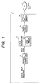
- FIG. 1 is a schematic block diagram showing an exemplary device 1 that includes an optical disc recording system (11 through 14) provided with an 4-to-6 modulator 12 according to the principles of the invention.
- the device 1 of FIG. 1 may be any device that can record multimedia information on an optical disc 2 by using the inventive 4-to-6 modulator 12.
- the device 1 includes a physical formatter 11, the 4-to-6 modulator 12, an NRZI converter 13 and an optical disc driver 14.
- the modulator 12 includes a 4-to-6 code system 120 comprising four code tables according to the principles of the invention. The code system or tables 120 will be detailed later.
- information to be recorded is obtained as a digital input sequence within the device or from the outside through an appropriate interface (not shown).
- the information may be video and/or audio information.
- the digital input sequence is supplied to the physical formatter 11.
- the physical formatter 11 formats the input sequence into a form suited for recording on the optical disc 2 by adding ECC (error correcting codes) and sync signals to the input sequence.
- the output from the formatter 11 is supplied as 4-bit input codes to the 4-to-6 modulator 12.
- the modulator 12 modulates the 4-bit input codes into 6-bit output codes in a manner as described in great detail later.
- the 6-bit output codes are NRZI converted into an NRZI signal.
- the optical disc driver 14 records the NRZI signal on the optical disc 2.
- FIG. 2 is a schematic block diagram showing an arrangement of the 4-to-6 modulator 12 of FIG. 1 .
- the modulator 12 is provided with a recording block generator 90 at the first stage thereof.
- the recording block generator 90 converts an input word sequence from the physical formatter 11 into a series of 4-bit code words so as to enable the following portion of the 4-to-6 modulator 12 to each of the code words.
- the 4-to-6 modulator 12 further comprises an alternative code existence checker 100; an output code retriever 110 for retrieving an output code according to the output from the alternative code existence checker 100; a first pair of a DSV calculator-and-memory (DSV1) 130 and output code queue memory (Q1) 131 having its input connected to a first output terminal of the code retriever 110; a second pair of a DSV calculator-and-memory (DSV2) 132 and output code queue memory (Q2) 133 having its input connected to a second output terminal of the code retriever 110; an absolute value comparator 140 for comparing the values DSV1 and DSV2 of the two DSV calculator-and-memories in response to the alternative code existence checker 100 output; and a memory/output controller 150 for outputting the contents (or digital output code sequence) of a relevant queue memory Q1 or Q2 according to the absolute value comparator 140 output.
- DSV1 DSV calculator-and-memory
- Q1 output code queue memory
- the alternative code existence checker 100 has read only memory for storing DSV-controllable input pattern data (detailed later), a first buffer memory for temporarily storing next table codes NT t-2 and NT t-1 associated with the input word of two words before and the previous input word, and a second buffer memory for storing the previous input word D t-1 as detailed later.
- the output code retriever 110 has a memory for temporary storing just used next table code as the next table code NT t-1 used for the previous input word D t-1.
- FIG. 3 is a diagram showing a table of 6-bit binary numbers and corresponding decimal numbers that satisfy the (1, 7) RLL constraints.
- the 6-bit binary numbers of FIG. 3 can be used to constitute a 4-to-6 code system in accordance with the principles of the invention.
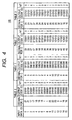
- FIG. 4 is a diagram showing an exemplary arrangement of a 4-to-6 code system according to an illustrative embodiment of the invention.
- the code system comprises an input data word column and four 4-to-6 code tables 0 through 3.
- the left-most column, i.e., the input data word column lists, in the ascending order, the 16 decimal numbers 0 through 15 corresponding to the possible input 4-bit data words (D).
- Each of the code tables 0 through 3 comprises an output code field or column that lists 16 6-bit output code (C) which correspond to the 16 decimal numbers (or the possible 4-bit data words); a next table (NT) field that contains next table (NT) codes each of which specifies the table number of the table from which an output code (C) should be selected for the next input data word; and a decimal number column that lists decimal numbers that correspond the output codes (C).
- C 6-bit output code
- NT next table
- NT next table
- decimal number column that lists decimal numbers that correspond the output codes (C).
- each next table code is so arranged that the overall code sequence when an output code (C) associated with the NT code is concatenated to the preceding code sequence still satisfies the (1, 7) RLL constraints.
- a data word sequence "4, 5, 6, 7, and 8" (actually in binary code though written in the decimal system for the sake of understanding) is supplied from the recording block generator 90.
- the output code retriever 110 uses a predetermined initial code table, e.g., the table 0 in an initial state.
- the retriever 110 may be so arranged that if the retriever 110 detects a specific sync code in the input code sequence, then the retriever 110 responsively uses the predetermined initial code table.
- the retriever 110 searches the initial table, i.e., table 0 in this example for the code to output an output code "18" (010010) and obtain an next table (NT) code "1" for the search for the next input data word. Then, in response to a reception of the next code "5", the retriever 110 searches table 1 according to the obtained NT code "1” for the code "5" to output an output code "2" (000010) and obtain an NT code "2". In response to a reception of the next code "6", the retriever 110 searches table 2 according to the obtained NT code "2” for the code "6” to output an output code "18” (010010) and obtain an NT code "3".
- the retriever 110 searches table 3 to output a code "41” (101001) and obtain an NT code "0".
- the retriever 110 searches table 0 to output a code "1" (000001) and obtain an NT code "1".
- the input code sequence "4, 5, 6, 7, and 8" causes the retriever 110 to supply output codes "010010, 000010, 010010, 101001, 000001". Concatenating these codes one after another yields an output code sequence "010010000010010010 101001000001". that satisfies the (1, 7) RLL constraints.
- the 4-to-6 code tables are so arranged that if one of specific patterns of three consecutive input words D t-2 ,
- an alternative output code (hereinafter, denoted by C2 t ) in an alternative code table different from an original code table specified by an NT t-1 code associated with the previous input word D t-1 may be used as an output code for the current input word D t and that the alternative output code C2 t and the original or regular output code (C1 t ) that is associated with the current input word D t in the table specified by the NT t-1 code associated with the previous input word D t-1 are different or opposite in, what we call, the odd/even property.
- the 4-to-6 code tables 120 contains four types of DSV-controllable input patterns as detailed in the following.
- next table code NT t-2 for an input word D t of two words before is "0" or "3”
- a previous input word D t-1 is "15” and a current input word D t is any of "0” through “3”
- an original output code C1 t is 010101, 010101, 100101 or 100101 obtained from table 3
- an alternative output code C2 t is 001001, 001001, 000101 or 000101 obtained from table 1.
- the original output codes C1 t are odd in the number of symbols "1” while the alternative output codes C2 t are even in the number of symbols "1".
- original or alternative output codes can be selected for the last input word (0, 1, 2 or 3) of this type of DSV-controllable input patterns so as to minimize the DSV value.
- FIG. 5 is a diagram showing four types of DSV-controllable input word patterns available with the 4-to-6 code system or tables of FIG. 4 .
- the checker 100 stores the four DSV-controllable input pattern data P1 through P4 and corresponding alternative table numbers AT1 through AT4 if the alternative table number varies depending on the type of an occurred DSV-controllable input pattern. Since an identical table 1 is used for the four patterns P1 through P4, the alternative code existence checker 100 has only to store the four DSV-controllable input pattern data P1 through P4 in this specific embodiment.
- the alternative code existence checker 100 receives an input data word Dk, then the alternative code existence checker 100 makes a test to see if the next table code NT t-2 of two words before and the previous input word D t-1 stored in not shown buffer memory coincides with any of the DSV-controllable input patterns P1 through P4 stored in the not-shown read only memory. If so, the alternative code existence checker 100 sends a DSV control signal indicative of the existence of an alternative code table or output code C2 t to the output code retriever 110 and the absolute value comparator 140, and stores the received input word D t as the previous input word D t-1 .
- the output code retriever 110 receives the input word D t without receiving the DSV control signal, then the output code retriever 110 responsively obtains an output code Ct and next table code NTt associated with the input word D t in a table specified by the next table code NT t-1 stored in the not-shown memory to launch the output code Ct into the two output terminals "1" and "2" and to supply the next table code NTt to the alternative code existence checker 100 while storing the next table code as NT t-1 in the not-shown memory.
- the output code retriever 110 receives both the input word D t and the DSV control signal, then the output code retriever 110 obtains, for the input code D t , not only an output code C1 t and next table code NT1 t in a table specified by the next table code NT t-1 stored in the not-shown memory but also an output code C2 t and next table code NT2 t in a table specified by the predetermined alternative table number AT stored in a read only memory (not shown).
- the output code retriever 110 launches the output codes C1 t and C2 t into the output terminals "1" and "2" respectively.
- the absolute value comparator 140 outputs a second DSV control signal indicative of the data path DP1 or DP2 that retains a smaller one of the DSV values DSVl t-1 and DSV2 t-1 .
- the output code retriever 110 supplies the alternative code existence checker 100 with one of the next table codes NT1 t and NT2 t which corresponds to the second DSV control signal and stores the supplied next table code as NT t-1 in the not-shown memory.
- the alternative code existence checker 100 stores the received next table code as NTt-1.
- the values DSV1 and DSV2 of the DSV memories 130 and 132 are equal to the DSV values calculated for the output codes till the last modulation cycle, i.e., DSV1 t-1 and DSV2 t-1 , respectively.
- the queue memories 131 and 133 stores output queues Q1 and Q2, respectively.
- the memory/output controller 150 outputs the contents of the queue memory (Q1 or Q2) of the data path (DP1 or DP2) in which the absolute value of the DSV memory contents is smaller.
- the 4-to-6 modulator 12 may be embodied by software.
- FIG. 6 is a flowchart showing a modulation operation performed by a not-shown CPU in the modulator 12 in accordance with the principles of the invention. Referring to FIGS. 2 and 6 , the operation of the modulator 12 is described in the following.
- an initial table (table 0 in a preferred embodiment) is first selected before accepting an input word sequence in step 401. Then, an input word Dt is input in step 403. An output code C1 t corresponding to the input word Dt is retrieved from the table specified by the next table code NT t-1 in step 405. The table for the current state is determined by the previous output code, and is assumed to be table 0 for the first code of an input word sequence.
- step 407 a test is made to see if any of the four DSV-controllable input patterns is detected.
- step 407 If the test result is NO in step 407, then the retrieved output code C1 t is appended to the ends of the queues Q1 and Q2 of the queue memory 131 in step 425.
- the values of the DSV memories DSV1 and DSV2 are updated with the last values of the queues Q1 and Q2 in step 419. Then, a test is made to see if the input word sequence has been exhausted in step 421. If so, then the content of Q1, if any, is output in step 423, and the operation is terminated. Otherwise, the control is returned to step 403.
- step 407 If the test result is YES in step 407, then the control is passed to step 409, where an alternative output code C2 t is retrieved from a predetermined alternative table. Further, in step 411, a test is made to see if the absolute value of DSV1 t-1 (the digital sum value stored in the DSV1 memory 130) is not larger than that of DSV2 t-1 (the digital sum value stored in the DSV2 memory 132).
- step 413 the output code sequence in the queue Q1, i.e., C1 t-1, C1 t-2,..., C1 Tdsvc is output as a part of the output code sequence from the 4-to-6 modulator 12; and .the DSV1 memory 130 contents or DSV1 t-1 is copied to the DSV2 memory 132 (These operations are executed by the memory/output controller 150 in case of hardware implementation).
- step 411 If the absolute value of DSV1 t-1 is larger than that of DSV2 t-1 in step 411, then the control is passed to step 415, where the output code sequence in the queue Q2, i.e., C1 t-1 , C1 t-2 ,..., C2 Tdsvc is output as a part of the output code sequence; and .the DSV2 memory 132 contents or DSV2 t-1 is copied to the DSV1 memory 130 (These operations are executed by the memory/output controller 150 in case of hardware implementation).
- step 417 the control is passed to step 417, where the retrieved codes C1 t and C2 t are appended to the output code queues Q1 and Q2, respectively. Then, the control is passed to the above-described step 419 and accordingly the description of the subsequent operation is omitted here.
- the 4-to-6 modulator modulates an input 4-bit code sequence into a 6-bit code sequence suited for NRZI recording on the optical disc.
- FIG. 7 is a schematic block diagram showing an exemplary device 3 that includes an optical disc playing system (31 through 34) provided with an 6-to-4 demodulator 33 according to the principles of the invention.
- the device 3 of FIG. 7 may be any device that includes the inventive 6-to-4 demodulator 33 to reproduce multimedia information that is recorded on an optical disc 2 by using the device 1 of FIG. 1 .
- the device 3 includes an optical disc driver 31, a code detector 32, the 6-to-4 demodulator 33 and a physical deformatter 34.
- the optical disc driver 31 reads a recorded signal on the optical disc 2.
- the code detector 32 detects a code sequence and a bit clock from the read signal.
- the 6-to-4 demodulator 33 uses the bit clock, the 6-to-4 demodulator 33 recovers 6-bit codes from the code sequence and demodulates the 6-bit codes into a 4-bit code sequence by using the code table 120 of FIG. 4 .
- the physical deformatter 34 removes ECC and sync signals from the 8-bit code sequence to provide a digital output sequence.
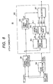
- FIG. 8 is a schematic block diagram showing an arrangement of the 6-to-4 demodulator 33 of FIG. 7 .
- the demodulator 33 comprises a sync detector 300 that receives a read code sequence and a bit clock and supplies a word clock, a serial/parallel converter 301 that receives the read code sequence and the bit clock and the word clock to output a 6-bit code sequence Ct, and a demodulator portion 302.
- the demodulator portion 302 comprises a decoding table searcher 303, a triple 1-word delay 304, a 1-word delay 305, a coding table searcher 306, and a selector 307.
- the coding table searcher 306 includes the above-described code table 120.
- the read code sequence from the code detector 32 is supplied to the sync detector 300 and the serial/parallel converter 301.
- the bit clock from the code detector 32 is supplied to the sync detector 300 and the serial/parallel converter 301.
- the sync detector 300 generates a word clock, which is used for recovering 6-bit codes from the read code sequence.
- the word clock is supplied to the serial/parallel converter 301 and the demodulator portion 302.
- the serial/parallel converter 301 converts each code of the read code sequence into a 6-bit code Ct, which is supplied to the decoding table searcher 303 and the coding table searcher 306.
- the decoding table searcher 303 includes a decoding table as shown in FIG. 9
- the second column is an input code (C) field that lists the possible 6-bit binary codes that satisfies the (1, 7) RLL constraints.
- the first column is a decimal number field that lists the decimal numbers corresponding to the 6-bit binary codes in the second column.
- the third column is a possible table (N) field that contains a possible table indicator (N) indicative of 4-to-6 code tables that might be used for the coding of the next input code C t+1 .
- the indicator N can have three values 0 through 2 as shown in the following table. Table 1 indicator N possible code tables used for C t+1 0 0 or 1 1 1, 2, or 3 2 2 or 3
- N is zero, then it indicates that the next code C t+1 might have been coded with table 0 or 1. If the indicator N is one, then the next code C t+1 might have been coded with table 1, 2 or 3. If the indicator N is two, then the next code C t+1 might have been coded with table 2 or 3.
- the fourth through seventh columns are four decoded data (D) fields labeled "0" through "3" which each indicate the used code table for coding of the next input code C t+1 .
- D decoded data
- T code table
- the variable UT serves as an decoded data field ID.
- the searcher 303 obtains a possible table indicator N t and all of decoded data words associated with the input code Ct and outputs all of the indicator N t and the decoded data words D1 t , D2 t and D3 t .
- the indicator N t is delayed by the 1-word delay 305 into N t-1 , which is in turn supplied to the decoding table searcher 306.
- the decoded data words D1 t , D2 t and D3 t are all delayed by the triple 1-word delay 304 into D1 t-1 , D2 t-1 and D3 t-1 , which are supplied to the selector 307.
- the coding table searcher 306 determines the 4-to-6 code table used for the next input code C t+1 by using the indicator N t which is supplied at the cycle time t+1. Specifically, the searcher 306 first searches the tables 0 through 3 for the code C t+1 . If the code C t+1 is found only in one table "T", then the searcher 306 determines that the code C t+1 was modulated with the table T to output the table number T as a decoded data field ID of the decoding table of FIG. 9 .
- the coding table searcher 306 further uses the indicator N t to decide the code table used for the code C t+1 referring to the above-described table 1.
- the selector 307 selects one of the received data words D1 t-1 , D2 t-1 and D3 t-1 .
- the algorithm of the demodulator 302 is shown in the C language in the following. If the possible table indicator N is 2, then the code word may have been exchanged for the DSV control. Such a situation is also included in the following algorithm.
Landscapes
- Engineering & Computer Science (AREA)
- Theoretical Computer Science (AREA)
- Signal Processing For Digital Recording And Reproducing (AREA)
Description
- The invention generally relates to optical disc recording or playing systems and, more particularly, to a method of and a system for modulating a 4-bit data sequence into a 6-bit code stream based on (1, 7) run-length-limited (RLL) constraints for digital data recording on an optical disc and to a demodulation method and system adapted for the modulation method and system.
- In recording on the optical disc or the magnetic disc, a channel coding or modulation scheme known as (1, 7) run-length-limited (RLL) constraints is widely used in view of optical transmission characteristics in recording and reading and physical restrictions involved in pit formation. In the channel coding, for the sake of servo control, the digital sum value (DSV) is controlled so as to satisfy a constraint on low-frequency components as is well known in the art. However, conventional (1,7) RLL scheme can not afford a satisfactory control of the DSV to some bit patterns to fail in suppression of DC components, resulting in, for example, information signal components mixing in the servo signal band. This presumably causes a problem of adversely affecting the servo performance.
- From this point of view,
Japanese unexamined patent publication No. 06195887 (1994 -
Japanese unexamined patent publication No. 10340543 (1998 - Though the publication
No. 06195887 - It is therefore an aim of the invention to provide a four-to-six modulation code system (or table), and a four-to-six modulation method and system that uses the modulation code table to provides a 6-bit code stream satisfying the (1, 7) RLL and DSV constraints without the need of merging bit or DSV control bit.
-
EP-A1-0,718,843 discloses a conversion table a part of which is duplexed in order to directly convert input M-bit data into an N-bit code without using a margin bit. This conversion table comprises first and second sub-tables each including a plurality of code groups, and these code groups contain different codes to the same input data. In the second sub-table, a part of the first sub-table obtaining by allocating different codes to the data ranging from the first input data to the second input data of the sub-table is duplexed. The set of the codes of the duplexed portion of the conversion table is so constituted as to take a digital sum variation of opposite signs, and codes are sequentially allocated to the input data from the code having the greater absolute value of the digital sum variation. In this way, low frequency components of modulation signals can be suppressed. -
US 5,175,545 discloses a digital code conversion system in a magnetic recording apparatus for converting one bit of an input digital signal into a signal of two bits, in which the number of binary digits of "0" making appearance between adjacent binary digits of "1" is two at minimum and seven at maximum. In the digital code resulting from the code conversion, ratio between maximum and minimum values of the density at which the binary digit of "1" makes appearance is 1:2. - According to an aspect of the invention, there is provided a method of modulating a 4-bit input word sequence into a 6-bit output code sequence which includes no merging bit and whose NRZI converted version satisfies (1, 7) run-length-limited constraints in a 4-to-6 modulator; characterised in that the method comprises the steps of:
- providing a 4-to-6 code system which has a column for storing 24 possible 4-bit input words in order of magnitude and a plurality of code tables, each code table comprising a table ID for identifying the code table and 24 combinations of 6-bit output codes and respective next table codes associated with the 24 possible 4-bit input words, each of said next table codes specifying a table ID of a code table to be used in a modulation of a next 4-bit input word of said input word sequence so as to cause said 6-bit output code sequence to satisfy said run-length-limited constraints, output codes being permitted to appear repeatedly in said 6-bit output codes in each code table such that combinations of appearances of each of said repeated output codes and respective next table codes are unique in said code table, storing at least one predetermined pattern which is expressed by a first input word of a predetermined input word range, a second input word preceding the first input word and a table ID of a code table to be used in a modulation of the second input word, wherein a first output code associated with the first input word in an original code table, which is specified by a next table code associated with the second input word of the predetermined pattern, can be replaced with a second output code associated with the first input word in an alternative code table assigned to the predetermined pattern, and wherein an odd/even property of the first output code is different from that of the second output code;
- retrieving a first output code associated with a first input word of said input word sequence from a code table identified by a next table code attached to the last modulated output code;
- making a test to see if said first input word, a second input word preceding said first input word in said input word sequence and a table ID of a code table to be used in a modulation of the second input word coincide with any of the predetermined patterns;
- in response to a pass in said test, retrieving a second output code associated with said first input word of said input word sequence from said alternative code table;
- calculating a first digital sum value and a second digital sum value by using said first output code and said second output code, respectively;
- if the absolute value of said second digital sum value is smaller than that of said first digital sum value, including said second output code in said 6-bit output code sequence; and
- if said test is unsuccessful or if the absolute of said second digital sum value is not smaller than that of said first digital sum value, including said first output code in said 6-bit output code sequence.
- According to another aspect of the invention there is provided a method of demodulating a 6-bit code sequence into a 4-bit code sequence in a 6-to-4 demodulator provided with:
- a decoding table for associating each of possible 6-bit current codes with an indicator and corresponding 4-bit codes further associated with respective table ID's for use in a demodulation of a next 6-bit code following a current 6-bit code, said indicator indicating a table list listing ID's of code tables that might be used for coding of said next 6-bit code; and
- means for associating a 6-bit code with at least one coding table ID from which said 6-bit code can be derived, characterised in that the method comprises the steps of:
- finding said indicator and said corresponding 4-bit codes from said decoding table by using said current 6-bit code;
- obtaining said at least one coding table ID for said next 6-bit code from said means by using said next 6-bit code;
- finding, as a next table ID for said next 6-bit code, a table ID common to said at least one coding table ID and table ID's listed in said table list indicated by said indicator; and
- obtaining a 4-bit code associated with said current 6-bit code and said common table ID and outputting said obtained 4-bit code.
- According to further aspect of the invention there is provided a system for modulating a 4-bit input word sequence into a 6-bit output code sequence which includes no merging bit and whose NRZI converted version satisfies (1, 7) run-length-limited constraints, characterised in that the system comprises:
- means for providing a 4-to-6 code system which has a column for storing 24 possible 4-bit input words in order of magnitude and a plurality of code tables, each code table comprising a table ID for identifying the code table and 24 combinations of 6-bit output codes and respective next table codes associated with the 24 possible 4-bit input words, each of said next table codes specifying a table ID of a code table to be used in a modulation of a next 4-bit input word of said input word sequence so as to cause said 6-bit output code sequence to satisfy said run-length-limited constraints, output codes being permitted to appear repeatedly in said 6-bit output codes in each code table such that combinations of appearances of each of said repeated output codes and respective next table codes are unique in said table,
- means for storing at least one predetermined pattern which is expressed by a first input word of a predetermined input word range, a second input word preceding the first input word and a table of a code table to be used in a modulation of the second input word, wherein a first output code associated with the first input word in an original code table, which is specified by a next table code associated with the second input word of the predetermined pattern, can be replaced with a second output code associated with the first input word in an alternative code
table assigned to the predetermined pattern, and wherein an odd/even property of the first output code is different from that of the second output code; - means for retrieving a first output code associated with a first input word of said input word sequence from a code table identified by a next table code attached to the last modulated output code;
- means for making a test to see if said first input word, a second input word preceding said first input word in said input word sequence and a table of a code table to be used in a modulation of the second input word coincide with any of the predetermined patterns;
- means, responsive to a pass in said test, for retrieving a second output code associated with said first input word of said input word sequence from said alternative code table;
- means for calculating a first digital sum value and a second digital sum value by using said first output code and said second output code, respectively;
- means, responsive to a determination that the absolute value of said second digital sum value is smaller than that of said first digital sum value, for including said second output code in said 6-bit output code sequence; and
- means, responsive to either a determination that said test is unsuccessful or a determination that the absolute of said second digital sum value is not smaller than that of said first digital sum value, for including said first output code in said 6-bit output code sequence.
- According to an aspect of the invention there is provided a system for demodulating a 6-bit code sequence into a 4-bit code sequence, characterised in that the system comprises:
- a decoding table for associating each of possible 6-bit current codes with an indicator and corresponding 4-bit codes further associated with respective table ID's for use in a demodulation of a next 6-bit code following a current 6-bit code, said indicator indicating a table list listing ID's of tables that might be used for coding of said next 6-bit code;
- means for associating a 6-bit code with at least one coding table ID from which said 6-bit code can be derived;
- means for finding said indicator and said corresponding 4-bit codes from said decoding table by using said current 6-bit code;
- means for obtaining said at least one coding table ID for said next 6-bit code from said means by using said next 6-bit code;
- means for finding, as a next table for said next 6-bit code, a table common to said at least one coding table ID and table ID's listed in said table list indicated by said indicator; and
- means for obtaining a 4-bit code associated with said current 6-bit code and said common table ID and outputting said obtained 4-bit code.
- The features and advantages of the present invention will be apparent from the following description of an exemplary embodiment of the invention and the accompanying drawings, in which:
-
FIG. 1 is a schematic block diagram showing anexemplary device 1 that includes an optical disc recording system (11 through 14) provided with an 4-to-6modulator 12 according to the principles of the invention; -
FIG. 2 is a schematic block diagram showing an arrangement of the 4-to-6modulator 12 ofFIG. 1 ; -
FIG. 3 is a diagram showing a table of 6-bit binary numbers and corresponding decimal numbers that satisfy the (1, 7) RLL constraints; -
FIG. 4 shows a code table according to an illustrative embodiment of the invention; -
FIG. 5 is a diagram showing four types of DSV-controllable input word patterns available with the 4-to-6 code system or tables ofFIG. 4 ; -
FIG. 6 is a flowchart showing a modulation operation performed by a not-shown CPU in themodulator 12 in accordance with the principles of the invention; -
FIG. 7 is a schematic block diagram showing anexemplary device 3 that includes an optical disc playing system (31 through 34) provided with an 6-to-4demodulator 33 according to the principles of the invention; -
FIG. 8 is a schematic block diagram showing an arrangement of the 6-to-4demodulator 33 ofFIG. 7 ; and -
FIG. 9 is a diagram showing a code table for use in the 6-to-4demodulator 33 ofFIG. 8 . - Throughout the drawing, the same elements when shown in more than one figure are designated by the same reference numerals.
-
FIG. 1 is a schematic block diagram showing anexemplary device 1 that includes an optical disc recording system (11 through 14) provided with an 4-to-6modulator 12 according to the principles of the invention. Thedevice 1 ofFIG. 1 may be any device that can record multimedia information on anoptical disc 2 by using the inventive 4-to-6modulator 12. Thedevice 1 includes aphysical formatter 11, the 4-to-6modulator 12, anNRZI converter 13 and anoptical disc driver 14. Themodulator 12 includes a 4-to-6code system 120 comprising four code tables according to the principles of the invention. The code system or tables 120 will be detailed later. - In optical disc recording operation, information to be recorded is obtained as a digital input sequence within the device or from the outside through an appropriate interface (not shown). The information may be video and/or audio information. The digital input sequence is supplied to the
physical formatter 11. Thephysical formatter 11 formats the input sequence into a form suited for recording on theoptical disc 2 by adding ECC (error correcting codes) and sync signals to the input sequence. The output from theformatter 11 is supplied as 4-bit input codes to the 4-to-6modulator 12. Themodulator 12 modulates the 4-bit input codes into 6-bit output codes in a manner as described in great detail later. The 6-bit output codes are NRZI converted into an NRZI signal. Theoptical disc driver 14 records the NRZI signal on theoptical disc 2. -
FIG. 2 is a schematic block diagram showing an arrangement of the 4-to-6modulator 12 ofFIG. 1 . Themodulator 12 is provided with arecording block generator 90 at the first stage thereof. Therecording block generator 90 converts an input word sequence from thephysical formatter 11 into a series of 4-bit code words so as to enable the following portion of the 4-to-6modulator 12 to each of the code words. The 4-to-6modulator 12 further comprises an alternativecode existence checker 100; anoutput code retriever 110 for retrieving an output code according to the output from the alternativecode existence checker 100; a first pair of a DSV calculator-and-memory (DSV1) 130 and output code queue memory (Q1) 131 having its input connected to a first output terminal of thecode retriever 110; a second pair of a DSV calculator-and-memory (DSV2) 132 and output code queue memory (Q2) 133 having its input connected to a second output terminal of thecode retriever 110; anabsolute value comparator 140 for comparing the values DSV1 and DSV2 of the two DSV calculator-and-memories in response to the alternativecode existence checker 100 output; and a memory/output controller 150 for outputting the contents (or digital output code sequence) of a relevant queue memory Q1 or Q2 according to theabsolute value comparator 140 output. - The alternative
code existence checker 100 has read only memory for storing DSV-controllable input pattern data (detailed later), a first buffer memory for temporarily storing next table codes NTt-2 and NTt-1 associated with the input word of two words before and the previous input word, and a second buffer memory for storing the previous input word Dt-1 as detailed later. Theoutput code retriever 110 has a memory for temporary storing just used next table code as the next table code NTt-1 used for the previous input word Dt-1. - Since the
modulator 12 requires thecode system 120 for operation, we discuss the code system or tables 120 prior to the description of the modulation operation. -
FIG. 3 is a diagram showing a table of 6-bit binary numbers and corresponding decimal numbers that satisfy the (1, 7) RLL constraints. The 6-bit binary numbers ofFIG. 3 can be used to constitute a 4-to-6 code system in accordance with the principles of the invention. -
FIG. 4 is a diagram showing an exemplary arrangement of a 4-to-6 code system according to an illustrative embodiment of the invention. The code system comprises an input data word column and four 4-to-6 code tables 0 through 3. The left-most column, i.e., the input data word column lists, in the ascending order, the 16decimal numbers 0 through 15 corresponding to the possible input 4-bit data words (D). Each of the code tables 0 through 3 comprises an output code field or column that lists 16 6-bit output code (C) which correspond to the 16 decimal numbers (or the possible 4-bit data words); a next table (NT) field that contains next table (NT) codes each of which specifies the table number of the table from which an output code (C) should be selected for the next input data word; and a decimal number column that lists decimal numbers that correspond the output codes (C). Though the decimal number columns have been added inFIG. 4 for facilitating understanding of the output code values, they are of course unnecessary for an actual code tables. - According to the principles of the invention, each next table code (NT) is so arranged that the overall code sequence when an output code (C) associated with the NT code is concatenated to the preceding code sequence still satisfies the (1, 7) RLL constraints. Assume that a data word sequence "4, 5, 6, 7, and 8" (actually in binary code though written in the decimal system for the sake of understanding) is supplied from the
recording block generator 90. It is also assumed that theoutput code retriever 110 uses a predetermined initial code table, e.g., the table 0 in an initial state. Alternatively, theretriever 110 may be so arranged that if theretriever 110 detects a specific sync code in the input code sequence, then theretriever 110 responsively uses the predetermined initial code table. Then, in responsive to a reception of the first 4-bit code "4", theretriever 110 searches the initial table, i.e., table 0 in this example for the code to output an output code "18" (010010) and obtain an next table (NT) code "1" for the search for the next input data word. Then, in response to a reception of the next code "5", theretriever 110 searches table 1 according to the obtained NT code "1" for the code "5" to output an output code "2" (000010) and obtain an NT code "2". In response to a reception of the next code "6", theretriever 110 searches table 2 according to the obtained NT code "2" for the code "6" to output an output code "18" (010010) and obtain an NT code "3". In the same manner, for the next code "7", theretriever 110 searches table 3 to output a code "41" (101001) and obtain an NT code "0". Finally, for the next code "8", theretriever 110 searches table 0 to output a code "1" (000001) and obtain an NT code "1". In this way, the input code sequence "4, 5, 6, 7, and 8" (decimal) causes theretriever 110 to supply output codes "010010, 000010, 010010, 101001, 000001". Concatenating these codes one after another yields an output code sequence
"010010000010010010 101001000001".
that satisfies the (1, 7) RLL constraints. - Hereinafter, an input data word at a certain time is expressed by a notation "Dt".
- According to the principles of the invention, the 4-to-6 code tables are so arranged that if one of specific patterns of three consecutive input words Dt-2,
- Dt-1 and Dt (Dt-2 is input earliest) has been input, then an alternative output code (hereinafter, denoted by C2t) in an alternative code table different from an original code table specified by an NTt-1 code associated with the previous input word Dt-1 may be used as an output code for the current input word Dt and that the alternative output code C2t and the original or regular output code (C1t) that is associated with the current input word Dt in the table specified by the NTt-1 code associated with the previous input word Dt-1 are different or opposite in, what we call, the odd/even property. That is, if the number of "1" symbols in the original output code (C1t) is even, then the number of "1" symbols of the alternative output code C2t is odd, and vice versa. Since it is possible to select one of two output codes C1t and C2t with different odd/even properties for the input word Dt of such specific patterns of three consecutive input words (which patterns are hereinafter, referred to as "DSV controllable input patterns"), selecting such an output code as makes the DSV smaller enables the control of the DSV without the need of margining bit while satisfying the (1, 7) RLL constraints. The 4-to-6 code tables 120 contains four types of DSV-controllable input patterns as detailed in the following.
- If the next table code NTt-2 for an input word Dt of two words before is "0" or "3", a previous input word Dt-1 is "15" and a current input word Dt is any of "0" through "3", then the previous output code Ct-1 is 010000 (=16 in decimal) and corresponding NTt-1 is 3 in either case of NTt-2 = 0 or 3; and though the current output code Ct for the current input word Dt (=0, 1, 2 or 3) should be found in table 3 specified by NTt-1, the
output code retriever 110 outputs both of the output codes C1t and C2t associated with the current input word Dt not only in table 3 specified by NTt-1 but also in a predetermined table 1 so that a suitable one of them C1t and C2t can be used for the DSV control in the following stage. In this example, an original output code C1t is 010101, 010101, 100101 or 100101 obtained from table 3, and an alternative output code C2t is 001001, 001001, 000101 or 000101 obtained from table 1. As seen from these codes, the original output codes C1t are odd in the number of symbols "1" while the alternative output codes C2t are even in the number of symbols "1". Thus, original or alternative output codes can be selected for the last input word (0, 1, 2 or 3) of this type of DSV-controllable input patterns so as to minimize the DSV value. -
FIG. 5 is a diagram showing four types of DSV-controllable input word patterns available with the 4-to-6 code system or tables ofFIG. 4 . InFIG. 5 , the just-described DSV-controllable input pattern is listed in the first record "1". If we denote an i-th DSV-controllable input pattern by Pi=(NTt-2, Dt-1, Dt) (i=2, 3, and 4), then the first DSV-controllable input pattern is expressed as:
- Similarly, the second through fourth DSV-controllable input patterns are be expressed as:


and
- It is noted that the alternative tables AT1 through AT4 for the last input words in the four DSV-controllable input patterns are advantageously identical, i.e., table 1 (i.e., AT1 = AT2 = AT3 = AT4 = 1). It is the alternative
code existence checker 100 that detects a DSV-controllable input pattern. For this purpose, thechecker 100 stores the four DSV-controllable input pattern data P1 through P4 and corresponding alternative table numbers AT1 through AT4 if the alternative table number varies depending on the type of an occurred DSV-controllable input pattern. Since an identical table 1 is used for the four patterns P1 through P4, the alternativecode existence checker 100 has only to store the four DSV-controllable input pattern data P1 through P4 in this specific embodiment. - Returning to
FIG. 2 , the modulation operation of the 4-to-6modulator 12 is described in the following. InFIG. 2 , an input data word for the current modulation cycle t is denoted by "Dt"; the output code for the current input code Dt is denoted by "C1t"; and an alternative (or optional) output code for Dt, if any, is denoted by "C2t". - If the alternative
code existence checker 100 receives an input data word Dk, then the alternativecode existence checker 100 makes a test to see if the next table code NTt-2 of two words before and the previous input word Dt-1 stored in not shown buffer memory coincides with any of the DSV-controllable input patterns P1 through P4 stored in the not-shown read only memory. If so, the alternativecode existence checker 100 sends a DSV control signal indicative of the existence of an alternative code table or output code C2t to theoutput code retriever 110 and theabsolute value comparator 140, and stores the received input word Dt as the previous input word Dt-1. - If the
output code retriever 110 receives the input word Dt without receiving the DSV control signal, then theoutput code retriever 110 responsively obtains an output code Ct and next table code NTt associated with the input word Dt in a table specified by the next table code NTt-1 stored in the not-shown memory to launch the output code Ct into the two output terminals "1" and "2" and to supply the next table code NTt to the alternativecode existence checker 100 while storing the next table code as NTt-1 in the not-shown memory. - If the
output code retriever 110 receives both the input word Dt and the DSV control signal, then theoutput code retriever 110 obtains, for the input code Dt, not only an output code C1t and next table code NT1t in a table specified by the next table code NTt-1 stored in the not-shown memory but also an output code C2t and next table code NT2t in a table specified by the predetermined alternative table number AT stored in a read only memory (not shown). Theoutput code retriever 110 launches the output codes C1t and C2t into the output terminals "1" and "2" respectively. In this case, in response to the DSV control signal from the alternativecode existence checker 100, theabsolute value comparator 140 outputs a second DSV control signal indicative of the data path DP1 or DP2 that retains a smaller one of the DSV values DSVlt-1 and DSV2t-1. In response to this second DSV control signal, theoutput code retriever 110 supplies the alternativecode existence checker 100 with one of the next table codes NT1t and NT2t which corresponds to the second DSV control signal and stores the supplied next table code as NTt-1 in the not-shown memory. Receiving the next table code from theoutput code retriever 110, the alternativecode existence checker 100 stores the received next table code as NTt-1. - Usually (except for a short period from the DSV value updating till the end of the modulation cycle), the values DSV1 and DSV2 of the
DSV memories - The
queue memories 
- The queue Q1 contains an alternative output code when the DSV control was last executed and the output codes for the modulation cycles from Tdsvc to t-1. That is,

- If an alternative output code exists (i.e., the alternative
code existence checker 100 has detected a DSV-controllable input pattern) or a DSV control is to be carried out in a modulation cycle t, the memory/output controller 150 outputs the contents of the queue memory (Q1 or Q2) of the data path (DP1 or DP2) in which the absolute value of the DSV memory contents is smaller. - Though we have shown, in
FIG. 2 , an example of hardware implementation of the 4-to-6modulator 12 ofFIG. 1 , the 4-to-6modulator 12 may be embodied by software. -
FIG. 6 is a flowchart showing a modulation operation performed by a not-shown CPU in themodulator 12 in accordance with the principles of the invention. Referring toFIGS. 2 and6 , the operation of themodulator 12 is described in the following. - As one of initial setting procedures, an initial table (table 0 in a preferred embodiment) is first selected before accepting an input word sequence in
step 401. Then, an input word Dt is input instep 403. An output code C1t corresponding to the input word Dt is retrieved from the table specified by the next table code NTt-1 instep 405. The table for the current state is determined by the previous output code, and is assumed to be table 0 for the first code of an input word sequence. - In
step 407, a test is made to see if any of the four DSV-controllable input patterns is detected. - If the test result is NO in
step 407, then the retrieved output code C1t is appended to the ends of the queues Q1 and Q2 of thequeue memory 131 instep 425. The values of the DSV memories DSV1 and DSV2 are updated with the last values of the queues Q1 and Q2 instep 419. Then, a test is made to see if the input word sequence has been exhausted instep 421. If so, then the content of Q1, if any, is output instep 423, and the operation is terminated. Otherwise, the control is returned to step 403. - If the test result is YES in
step 407, then the control is passed to step 409, where an alternative output code C2t is retrieved from a predetermined alternative table. Further, instep 411, a test is made to see if the absolute value of DSV1t-1 (the digital sum value stored in the DSV1 memory 130) is not larger than that of DSV2t-1 (the digital sum value stored in the DSV2 memory 132). If so, the control is passed to step 413, where the output code sequence in the queue Q1, i.e., C1t-1, C1t-2,..., C1Tdsvc is output as a part of the output code sequence from the 4-to-6modulator 12; and .theDSV1 memory 130 contents or DSV1t-1 is copied to the DSV2 memory 132 (These operations are executed by the memory/output controller 150 in case of hardware implementation). - If the absolute value of DSV1t-1 is larger than that of DSV2t-1 in
step 411, then the control is passed to step 415, where the output code sequence in the queue Q2, i.e., C1t-1, C1t-2,..., C2Tdsvc is output as a part of the output code sequence; and .theDSV2 memory 132 contents or DSV2t-1 is copied to the DSV1 memory 130 (These operations are executed by the memory/output controller 150 in case of hardware implementation). - Following
step step 419 and accordingly the description of the subsequent operation is omitted here. - In this way, the 4-to-6 modulator modulates an input 4-bit code sequence into a 6-bit code sequence suited for NRZI recording on the optical disc.
-
FIG. 7 is a schematic block diagram showing anexemplary device 3 that includes an optical disc playing system (31 through 34) provided with an 6-to-4demodulator 33 according to the principles of the invention. Thedevice 3 ofFIG. 7 may be any device that includes the inventive 6-to-4demodulator 33 to reproduce multimedia information that is recorded on anoptical disc 2 by using thedevice 1 ofFIG. 1 . Thedevice 3 includes anoptical disc driver 31, acode detector 32, the 6-to-4demodulator 33 and aphysical deformatter 34. - In optical disc playing operation, the
optical disc driver 31 reads a recorded signal on theoptical disc 2. Thecode detector 32 detects a code sequence and a bit clock from the read signal. Using the bit clock, the 6-to-4demodulator 33 recovers 6-bit codes from the code sequence and demodulates the 6-bit codes into a 4-bit code sequence by using the code table 120 ofFIG. 4 . Thephysical deformatter 34 removes ECC and sync signals from the 8-bit code sequence to provide a digital output sequence. -
FIG. 8 is a schematic block diagram showing an arrangement of the 6-to-4demodulator 33 ofFIG. 7 . Thedemodulator 33 comprises async detector 300 that receives a read code sequence and a bit clock and supplies a word clock, a serial/parallel converter 301 that receives the read code sequence and the bit clock and the word clock to output a 6-bit code sequence Ct, and ademodulator portion 302. Thedemodulator portion 302 comprises adecoding table searcher 303, a triple 1-word delay 304, a 1-word delay 305, acoding table searcher 306, and aselector 307. Thecoding table searcher 306 includes the above-described code table 120. - The read code sequence from the
code detector 32 is supplied to thesync detector 300 and the serial/parallel converter 301. The bit clock from thecode detector 32 is supplied to thesync detector 300 and the serial/parallel converter 301. Thesync detector 300 generates a word clock, which is used for recovering 6-bit codes from the read code sequence. The word clock is supplied to the serial/parallel converter 301 and thedemodulator portion 302. - Using the word clock, the serial/
parallel converter 301 converts each code of the read code sequence into a 6-bit code Ct, which is supplied to thedecoding table searcher 303 and thecoding table searcher 306. Thedecoding table searcher 303 includes a decoding table as shown inFIG. 9 - In
FIG. 9 , the second column is an input code (C) field that lists the possible 6-bit binary codes that satisfies the (1, 7) RLL constraints. The first column is a decimal number field that lists the decimal numbers corresponding to the 6-bit binary codes in the second column. - The third column is a possible table (N) field that contains a possible table indicator (N) indicative of 4-to-6 code tables that might be used for the coding of the next input code Ct+1. The indicator N can have three
values 0 through 2 as shown in the following table.Table 1 indicator N possible code tables used for C t+10 0 or 1 1 1, 2, or 3 2 2 or 3 - If N is zero, then it indicates that the next code Ct+1 might have been coded with table 0 or 1. If the indicator N is one, then the next code Ct+1 might have been coded with table 1, 2 or 3. If the indicator N is two, then the next code Ct+1 might have been coded with table 2 or 3.
- The fourth through seventh columns are four decoded data (D) fields labeled "0" through "3" which each indicate the used code table for coding of the next input code Ct+1. For example, if the next code Ct+1 has been modulated by using code table T (T= 0, 1, 2, or 3), then the seeking 4-bit output word for the input code Ct is found at the intersection of the record "Ct" and the column of UT = T. In this example, the variable UT serves as an decoded data field ID.
- Returning to
FIG. 8 , if thedecoding table searcher 303 receives the input code Ct, then thesearcher 303 obtains a possible table indicator Nt and all of decoded data words associated with the input code Ct and outputs all of the indicator Nt and the decoded data words D1t, D2t and D3t. The indicator Nt is delayed by the 1-word delay 305 into Nt-1, which is in turn supplied to thedecoding table searcher 306. The decoded data words D1t, D2t and D3t are all delayed by the triple 1-word delay 304 into D1t-1, D2t-1 and D3t-1, which are supplied to theselector 307. - The
coding table searcher 306 determines the 4-to-6 code table used for the next input code Ct+1 by using the indicator Nt which is supplied at the cycletime t+ 1. Specifically, thesearcher 306 first searches the tables 0 through 3 for the code Ct+1. If the code Ct+1 is found only in one table "T", then thesearcher 306 determines that the code Ct+1 was modulated with the table T to output the table number T as a decoded data field ID of the decoding table ofFIG. 9 . However, if the next input code Ct+1 is found in more than one code tables (for example, Ct+1 = 18 is found in tables 0 and 2), thecoding table searcher 306 further uses the indicator Nt to decide the code table used for the code Ct+1 referring to the above-described table 1. - By using the decoded data field ID UT, the
selector 307 selects one of the received data words D1t-1, D2t-1 and D3t-1. - For example, we assume that an
input code sequence - The algorithm of the
demodulator 302 is shown in the C language in the following. If the possible table indicator N is 2, then the code word may have been exchanged for the DSV control. Such a situation is also included in the following algorithm.


- Many widely different embodiments of the present invention may be constructed.
- It should be understood that the present invention is not limited to the specific embodiments described in the specification, except as defined in the appended claims.
Claims (7)
- A method of modulating a 4-bit input word sequence into a 6-bit output code sequence which includes no merging bit and whose NRZI converted version satisfies (1, 7) run-length-limited constraints in a 4-to-6 modulator (12); characterised in that the method comprises the steps of:providing a 4-to-6 code system (120) which has a column for storing 24 possible 4-bit input words in order of magnitude and a plurality of code tables, each code table comprising a table ID for identifying the code table and 24 combinations of 6-bit output codes and respective next table codes associated with the 24 possible 4-bit input words, each of said next table codes specifying a table ID of a code table to be used in a modulation of a next 4-bit input word of said input word sequence so as to cause said 6-bit output code sequence to satisfy said run-length-limited constraints, output codes being permitted to appear repeatedly in said 6-bit output codes in each code table such that combinations of appearances of each of said repeated output codes and respective next table codes are unique in said code table;storing at least one predetermined pattern which is expressed by a first input word of a predetermined input word range, a second input word preceding the first input word and a table ID of a code table to be used in a modulation of the second input word, wherein a first output code associated with the first input word in an original code table, which is specified by a next table code associated with the second input word of the predetermined pattern, can be replaced with a second output code associated with the first input word in an alternative code table assigned to the predetermined pattern,and wherein an odd/even property of the first output code is different from that of the second output code;retrieving a first output code associated with a first input word of said input word sequence from a code table identified by a next table code attached to the last modulated output code;making a test to see if said first input word, a second input word preceding said first input word in said input word sequence and a table ID of a code table to be used in a modulation of the second input word coincide with any of the predetermined patterns;in response to a pass in said test, retrieving a second output code associated with said first input word of said input word sequence from said alternative code table;calculating a first digital sum value and a second digital sum value by using said first output code and said second output code, respectively;if the absolute value of said second digital sum value is smaller than that of said first digital sum value, including said second output code in said 6-bit output code sequence; andif said test is unsuccessful or if the absolute of said second digital sum value is not smaller than that of said first digital sum value, including said first output code in said 6-bit output code sequence.
- A method as defined claim 1, further comprising the steps of:storing said first digital sum value and said second digital sum value in first and second locations, respectively;prior to said step of calculating said first digital sum value and said second digital sum value, comparing a third absolute value of the first digital sum value stored in said first location and a second absolute value of the second digital sum value stored in said second location;in response to said pass in said test, appending said first and second output codes to a first output code queue and a second output code queue, respectively; andin response to a failure in said test, appending said first output code to said first output code queue and said second output code queue,wherein said step of including said second output code comprises the step of, if said second absolute value is smaller than said first absolute value, outputting the contents of said second output code queue, and
wherein said step of including said first output code comprises the step of, if said test is unsuccessful or if said second absolute value is not smaller than said first absolute value, outputting the contents of said first output code queue. - The method according to claim 1 or claim 2, further comprising storing said output code sequence onto an optical disc (2).
- A method of demodulating a 6-bit code sequence into a 4-bit code sequence in a 6-to-4 demodulator (33) provided with:a decoding table (303) for associating each of possible 6-bit current codes with an indicator and corresponding 4-bit codes further associated with respective table ID's for use in a demodulation of a next 6-bit code following a current 6-bit code, said indicator indicating a table list listing ID's of code tables that might be used for coding of said next 6-bit code; andmeans (303) for associating a 6-bit code with at least one coding table ID from which said 6-bit code can be derived, characterised in that the method comprises the steps of:finding said indicator and said corresponding 4-bit codes from said decoding table by using said current 6-bit code;obtaining said at least one coding table ID for said next 6-bit code from said means by using said next 6-bit code;finding, as a next table ID for said next 6-bit code, a table ID common to said at least one coding table ID and table ID's listed in said table list indicated by said indicator; andobtaining a 4-bit code associated with said current 6-bit code and said common table ID and outputting said obtained 4-bit code.
- A system for modulating (12) a 4-bit input word sequence into a 6-bit output code sequence which includes no merging bit and whose NRZI converted version satisfies (1, 7) run-length-limited constraints, characterised in that the system comprises:means (110) for providing a 4-to-6 code system (120) which has a column for storing 24 possible 4-bit input words in order of magnitude and a plurality of code tables, each code table comprising a table ID for identifying the code table and 24 combinations of 6-bit output codes and respective next table codes associated with the 24 possible 4-bit input words, each of said next table codes specifying a table ID of a code table to be used in a modulation of a next 4-bit input word of said input word sequence so as to cause said 6-bit output code sequence to satisfy said run-length-limited constraints, output codes being permitted to appear repeatedly in said 6-bit output codes in each code table such that combinations of appearances of each of said repeated output codes and respective next table codes are unique in said table,means (100) for storing at least one predetermined pattern (P1-P4) which is expressed by a first input word of a predetermined input word range, a second input word preceding the first input word and a table ID of a code table to be used in a modulation of the second input word, wherein a first output code associated with the first input word in an original code table, which is specified by a next table code associated with the second input word of the predetermined pattern, can be replaced with a second output code associated with the first input word in an alternative code table assigned to the predetermined pattern, and wherein an odd/even property of the first output code is different from that of the second output code;means (110) for retrieving a first output code associated with a first input word of said input word sequence from a code table identified by a next table code attached to the last modulated output code;means (110) for making a test to see if said first input word, a second input word preceding said first input word in said input word sequence and a table of a code table to be used in a modulation of the second input word coincide with any of the predetermined patterns;means (110), responsive to a pass in said test, for retrieving a second output code associated with said first input word of said input word sequence from said alternative code table;means (130, 132) for calculating a first digital sum value and a second digital sum value by using said first output code and said second output code, respectively;means (110), responsive to a determination that the absolute value of said second digital sum value is smaller than that of said first digital sum value, for including said second output code in said 6-bit output code sequence; andmeans (110), responsive to either a determination that said test is unsuccessful or a determination that the absolute of said second digital sum value is not smaller than that of said first digital sum value, for including said first output code in said 6-bit output code sequence.
- The system as defined claim 5, further comprising:means (131; 133) for storing said first digital sum value and said second digital sum value in first and second locations, respectively;means (140), operative prior to said means for calculating said first digital sum value and said second digital sum value, for comparing a first absolute value of the first digital sum value stored in said first location and a second absolute value of the second digital sum value stored in said second location,means (110), responsive to said pass in said test, for appending said first and second output codes to a first output code queue and a second output code queue, respectively; andmeans (110), responsive to a failure in said test, for appending said first output code to said first output code queue and said second output code queue, wherein said means for including said second output code comprises means, in the event said second absolute value is smaller than said first absolute value, for outputting the contents of said second output code queue, and wherein said means for including said first output code comprises means, in the event said test is unsuccessful or in the event said second absolute value is not smaller than said first absolute value, for outputting the contents of said first output code queue.
- A system for demodulating a 6-bit code sequence into a 4-bit code sequence, characterised in that the system comprises:a decoding table (303) for associating each of possible 6-bit current codes with an indicator and corresponding 4-bit codes further associated with respective table ID's for use in a demodulation of a next 6-bit code following a current 6-bit code, said indicator indicating a table list listing ID's of tables that might be used for coding of said next 6-bit code;means (303) for associating a 6-bit code with at least one coding table ID from which said 6-bit code can be derived;means (303) for finding said indicator and said corresponding 4-bit codes from said decoding table by using said current 6-bit code;means (303) for obtaining said at least one coding table ID for said next 6-bit code from said means by using said next 6-bit code;means (303) for finding, as a next table ID for said next 6-bit code, a table ID common to said at least one coding table ID and table ID's listed in said table list indicated by said indicator; andmeans (306) for obtaining a 4-bit code associated with said current 6-bit code and said common table ID and outputting said obtained 4-bit code.
Applications Claiming Priority (2)
| Application Number | Priority Date | Filing Date | Title |
|---|---|---|---|
| JP14457599 | 1999-05-25 | ||
| JP14457599A JP3551359B2 (en) | 1999-05-25 | 1999-05-25 | Modulator, demodulator |
Publications (3)
| Publication Number | Publication Date |
|---|---|
| EP1056209A2 EP1056209A2 (en) | 2000-11-29 |
| EP1056209A3 EP1056209A3 (en) | 2002-04-17 |
| EP1056209B1 true EP1056209B1 (en) | 2008-03-19 |
Family
ID=15365375
Family Applications (1)
| Application Number | Title | Priority Date | Filing Date |
|---|---|---|---|
| EP00303810A Expired - Lifetime EP1056209B1 (en) | 1999-05-25 | 2000-05-05 | Four-to-six code table, modulation using same but no merging bit, their application to optical disc recording or playing systems |
Country Status (4)
| Country | Link |
|---|---|
| US (1) | US6300886B1 (en) |
| EP (1) | EP1056209B1 (en) |
| JP (1) | JP3551359B2 (en) |
| DE (1) | DE60038333T2 (en) |
Families Citing this family (25)
| Publication number | Priority date | Publication date | Assignee | Title |
|---|---|---|---|---|
| US6297753B1 (en) * | 1999-01-29 | 2001-10-02 | Victor Company Of Japan, Ltd. | Eight-to-fifteen modulation using no merging bit and optical disc recording or reading systems based thereon |
| US6445313B2 (en) * | 2000-02-07 | 2002-09-03 | Lg Electronics Inc. | Data modulating/demodulating method and apparatus for optical recording medium |
| KR100726083B1 (en) * | 2000-04-14 | 2007-06-08 | 엘지전자 주식회사 | Optical Recording Medium And Method of Modulating and Demodulating Data thereof |
| KR20010096009A (en) * | 2000-04-15 | 2001-11-07 | 박순배 | Modulation code for communication and multimedia |
| JP3664091B2 (en) | 2001-01-12 | 2005-06-22 | 日本ビクター株式会社 | Modulation method, modulation device, demodulation method, demodulation device, method of recording on information recording medium, information transmission method and information transmission device |
| US6853320B2 (en) | 2001-01-16 | 2005-02-08 | Victor Company Of Japan, Ltd. | Modulation system |
| JP2002304859A (en) * | 2001-02-02 | 2002-10-18 | Victor Co Of Japan Ltd | Synchronous signal generating method, recording apparatus, transmitting apparatus, recording medium, and transmission medium |
| JP2002271205A (en) | 2001-03-09 | 2002-09-20 | Victor Co Of Japan Ltd | Modulation method, modulator, demodulation method, demodulator, information recoding medium, information transmitting method and information transmitting equipment |
| KR100531781B1 (en) * | 2001-03-26 | 2005-11-29 | 엘지전자 주식회사 | Method and apparatus for modulating digital data and medium for recording modulated data generated thereby |
| CN100456640C (en) | 2001-06-07 | 2009-01-28 | 日本胜利株式会社 | Modulation-demodulation method and device, information transmission method and device and recording medium |
| JP3964634B2 (en) | 2001-06-14 | 2007-08-22 | 株式会社東芝 | Synchronization code generating method, information recording method, information reproducing method, information reproducing apparatus, and information storage medium |
| CN100428633C (en) * | 2001-06-29 | 2008-10-22 | 日本胜利株式会社 | Method and apparatus for modulating digital signal and recording medium |
| JP2003085898A (en) | 2001-09-12 | 2003-03-20 | Toshiba Corp | Information storing medium, information recording device, information recording method, and information reproducing device, and information reproducing method |
| JP2003168222A (en) | 2001-09-20 | 2003-06-13 | Victor Co Of Japan Ltd | Information recording carrier, and reproducing method and device for the same |
| US7177262B2 (en) | 2002-04-19 | 2007-02-13 | Victor Company Of Japan, Ltd. | Reproducing system and corresponding information recording medium having wobbled land portions |
| JP2004013947A (en) | 2002-06-04 | 2004-01-15 | Victor Co Of Japan Ltd | Information recording carrier, device and method for reproducing, for recording, and for recording/reproducing |
| AU2003278427A1 (en) * | 2002-11-05 | 2004-06-07 | Koninklijke Philips Electronics N.V. | Record carrier comprising an additional sync-color pattern and method and device for use with such record carrier |
| JP3957679B2 (en) | 2002-12-18 | 2007-08-15 | 日本電気株式会社 | Coded modulation method and modulation device, demodulation method and demodulation device, information recording medium |
| JP2004213767A (en) | 2002-12-27 | 2004-07-29 | Toshiba Corp | Data converting device and data converting method |
| US7557739B1 (en) * | 2006-10-17 | 2009-07-07 | Marvell International Ltd. | Four-to-six modulation encoder |
| JP5284069B2 (en) | 2008-12-11 | 2013-09-11 | 株式会社東芝 | Memory system and memory access method |
| JP2011238301A (en) * | 2010-05-06 | 2011-11-24 | Sony Corp | Encoder, encoding method, recording device, recording method, optical recording medium, decoder and decoding method |
| JP5563125B2 (en) * | 2013-05-29 | 2014-07-30 | 株式会社東芝 | Memory access device |
| US12045220B2 (en) * | 2022-08-25 | 2024-07-23 | Databricks, Inc. | Efficient merge of tabular data with deletion indications |
| US12056126B2 (en) | 2022-08-25 | 2024-08-06 | Databricks, Inc. | Efficient merging of tabular data with post-processing compaction |
Family Cites Families (11)
| Publication number | Priority date | Publication date | Assignee | Title |
|---|---|---|---|---|
| JPS57176866A (en) * | 1981-04-24 | 1982-10-30 | Sony Corp | Encoder of binary signal |
| US4547890A (en) * | 1982-09-28 | 1985-10-15 | Abraham M. Gindi | Apparatus and method for forming d.c. free codes |
| US4684921A (en) * | 1985-06-13 | 1987-08-04 | International Business Machines Corporation | RLL (1,7) encoder with single state bit |
| JPH01286626A (en) * | 1988-01-18 | 1989-11-17 | Hitachi Ltd | Data encoding system |
| JP3334810B2 (en) * | 1992-02-14 | 2002-10-15 | ソニー株式会社 | Encoding method, reproducing method, and reproducing apparatus |
| JP3224418B2 (en) * | 1992-05-21 | 2001-10-29 | パイオニア株式会社 | Recording data string secondary modulation method |
| JPH0612449A (en) * | 1992-06-29 | 1994-01-21 | Canon Inc | System and method for machine translation |
| JP2768174B2 (en) | 1992-10-13 | 1998-06-25 | 日本電気株式会社 | Recording code modulator |
| JP3541439B2 (en) * | 1994-07-08 | 2004-07-14 | ソニー株式会社 | Signal modulation method and apparatus, and signal demodulation apparatus and method |
| JPH10340543A (en) | 1997-04-08 | 1998-12-22 | Sony Corp | Encoding device, decoding device, encoding method and decoding method therefor |
| US5969649A (en) * | 1998-02-17 | 1999-10-19 | International Business Machines Corporation | Run length limited encoding/decoding with robust resync |
-
1999
- 1999-05-25 JP JP14457599A patent/JP3551359B2/en not_active Expired - Fee Related
-
2000
- 2000-04-18 US US09/551,835 patent/US6300886B1/en not_active Expired - Lifetime
- 2000-05-05 EP EP00303810A patent/EP1056209B1/en not_active Expired - Lifetime
- 2000-05-05 DE DE60038333T patent/DE60038333T2/en not_active Expired - Lifetime
Also Published As
| Publication number | Publication date |
|---|---|
| EP1056209A3 (en) | 2002-04-17 |
| JP2000332613A (en) | 2000-11-30 |
| DE60038333T2 (en) | 2009-04-30 |
| US6300886B1 (en) | 2001-10-09 |
| EP1056209A2 (en) | 2000-11-29 |
| JP3551359B2 (en) | 2004-08-04 |
| DE60038333D1 (en) | 2008-04-30 |
Similar Documents
| Publication | Publication Date | Title |
|---|---|---|
| EP1056209B1 (en) | Four-to-six code table, modulation using same but no merging bit, their application to optical disc recording or playing systems | |
| US6297753B1 (en) | Eight-to-fifteen modulation using no merging bit and optical disc recording or reading systems based thereon | |
| KR100352353B1 (en) | Signal modulation method, signal modulation apparatus, signal demodulation method and signal demodulation apparatus | |
| JP3457093B2 (en) | Recording medium, digital modulation / demodulation method and device therefor | |
| JPH10508456A (en) | Method for converting a sequence of m-bit information words into a modulated signal, method for manufacturing a record carrier, coding apparatus, apparatus, recording apparatus, signal and record carrier | |
| KR20010041154A (en) | Device for encoding n-bit source words into corresponding m-bit channel words and decoding m-bit channel words into corresponding n-bit source words | |
| US6175318B1 (en) | Device for encoding/decoding n-bit source words into corresponding m-bit channel words, and vice versa | |
| KR100573626B1 (en) | Apparatus and method for converting a sequence of m-bit information words into a modulated signal | |
| US6265994B1 (en) | Device for encoding/decoding n-bit source words into corresponding m-bit channel words, and vice versa | |
| US6559779B2 (en) | Data encoding method, apparatus, and storage medium | |
| US6967597B1 (en) | Method and apparatus for coding information, method and apparatus for decoding information, method of fabricating a recording medium, the recording medium and modulated signal | |
| US6639524B2 (en) | Method and apparatus for coding information, method and apparatus for decoding coded information, method of fabricating a recording medium, the recording medium and modulated signal | |
| US5969651A (en) | Signal modulating method, signal modulating apparatus, signal demodulating method and signal demodulating apparatus | |
| US6353912B1 (en) | Encoding circuit, encoding method, digital signal transmitting apparatus, and digital signal recording/reproducing apparatus | |
| JP4095440B2 (en) | Apparatus and method for encoding information, apparatus and method for decoding the encoded information, modulation signal, and recording medium manufacturing method | |
| US6985094B2 (en) | Method for coding a data stream | |
| KR100470026B1 (en) | Method and apparatus for coding/decoding information | |
| JPH08204573A (en) | Code conversion method | |
| JP2002533975A (en) | Apparatus for encoding n-bit source words into corresponding m-bit channel words and decoding m-bit channel words into corresponding n-bit source words | |
| KR100575638B1 (en) | Method and apparatus for coding information, method and apparatus for decoding coded information, method of fabricating a recording medium, the recording medium and modulated signal | |
| JP3018980B2 (en) | Recording code converter | |
| KR20040075947A (en) | System of converting information words to a signal | |
| JP2004220766A (en) | Modulation method, modulation device, demodulation method, demodulation device, information recording medium, information transmitting method and device, | |
| JPH01221918A (en) | Variable length code converter | |
| JP2006129506A (en) | Apparatus and method for encoding information, apparatus and method for decoding encoded information thereof, and method for manufacturing modulation signal and recording medium |
Legal Events
| Date | Code | Title | Description |
|---|---|---|---|
| PUAI | Public reference made under article 153(3) epc to a published international application that has entered the european phase |
Free format text: ORIGINAL CODE: 0009012 |
|
| AK | Designated contracting states |
Kind code of ref document: A2 Designated state(s): AT BE CH CY DE DK ES FI FR GB GR IE IT LI LU MC NL PT SE Kind code of ref document: A2 Designated state(s): DE FR GB |
|
| AX | Request for extension of the european patent |
Free format text: AL;LT;LV;MK;RO;SI |
|
| PUAL | Search report despatched |
Free format text: ORIGINAL CODE: 0009013 |
|
| AK | Designated contracting states |
Kind code of ref document: A3 Designated state(s): AT BE CH CY DE DK ES FI FR GB GR IE IT LI LU MC NL PT SE |
|
| AX | Request for extension of the european patent |
Free format text: AL;LT;LV;MK;RO;SI |
|
| RIC1 | Information provided on ipc code assigned before grant |
Free format text: 7H 03M 5/14 A, 7G 11B 20/14 B |
|
| 17P | Request for examination filed |
Effective date: 20020610 |
|
| AKX | Designation fees paid |
Free format text: DE FR GB |
|
| GRAP | Despatch of communication of intention to grant a patent |
Free format text: ORIGINAL CODE: EPIDOSNIGR1 |
|
| GRAS | Grant fee paid |
Free format text: ORIGINAL CODE: EPIDOSNIGR3 |
|
| GRAA | (expected) grant |
Free format text: ORIGINAL CODE: 0009210 |
|
| AK | Designated contracting states |
Kind code of ref document: B1 Designated state(s): DE FR GB |
|
| REG | Reference to a national code |
Ref country code: GB Ref legal event code: FG4D |
|
| REF | Corresponds to: |
Ref document number: 60038333 Country of ref document: DE Date of ref document: 20080430 Kind code of ref document: P |
|
| ET | Fr: translation filed | ||
| PLBE | No opposition filed within time limit |
Free format text: ORIGINAL CODE: 0009261 |
|
| STAA | Information on the status of an ep patent application or granted ep patent |
Free format text: STATUS: NO OPPOSITION FILED WITHIN TIME LIMIT |
|
| 26N | No opposition filed |
Effective date: 20081222 |
|
| REG | Reference to a national code |
Ref country code: DE Ref legal event code: R082 Ref document number: 60038333 Country of ref document: DE Representative=s name: MANITZ, FINSTERWALD & PARTNER GBR, DE |
|
| REG | Reference to a national code |
Ref country code: DE Ref legal event code: R082 Ref document number: 60038333 Country of ref document: DE Representative=s name: MANITZ FINSTERWALD PATENTANWAELTE PARTMBB, DE Effective date: 20120430 Ref country code: DE Ref legal event code: R082 Ref document number: 60038333 Country of ref document: DE Representative=s name: MANITZ, FINSTERWALD & PARTNER GBR, DE Effective date: 20120430 Ref country code: DE Ref legal event code: R081 Ref document number: 60038333 Country of ref document: DE Owner name: JVC KENWOOD CORPORATION, JP Free format text: FORMER OWNER: VICTOR COMPANY OF JAPAN, LTD., YOKOHAMA, JP Effective date: 20120430 Ref country code: DE Ref legal event code: R081 Ref document number: 60038333 Country of ref document: DE Owner name: JVC KENWOOD CORPORATION, YOKOHAMA-SHI, JP Free format text: FORMER OWNER: VICTOR COMPANY OF JAPAN, LTD., YOKOHAMA, KANAGAWA, JP Effective date: 20120430 |
|
| REG | Reference to a national code |
Ref country code: FR Ref legal event code: TP Owner name: JVC KENWOOD CORPORATION, JP Effective date: 20120705 |
|
| REG | Reference to a national code |
Ref country code: FR Ref legal event code: PLFP Year of fee payment: 17 |
|
| REG | Reference to a national code |
Ref country code: FR Ref legal event code: PLFP Year of fee payment: 18 |
|
| PGFP | Annual fee paid to national office [announced via postgrant information from national office to epo] |
Ref country code: FR Payment date: 20170413 Year of fee payment: 18 Ref country code: GB Payment date: 20170503 Year of fee payment: 18 Ref country code: DE Payment date: 20170502 Year of fee payment: 18 |
|
| REG | Reference to a national code |
Ref country code: DE Ref legal event code: R119 Ref document number: 60038333 Country of ref document: DE |
|
| GBPC | Gb: european patent ceased through non-payment of renewal fee |
Effective date: 20180505 |
|
| PG25 | Lapsed in a contracting state [announced via postgrant information from national office to epo] |
Ref country code: FR Free format text: LAPSE BECAUSE OF NON-PAYMENT OF DUE FEES Effective date: 20180531 Ref country code: DE Free format text: LAPSE BECAUSE OF NON-PAYMENT OF DUE FEES Effective date: 20181201 Ref country code: GB Free format text: LAPSE BECAUSE OF NON-PAYMENT OF DUE FEES Effective date: 20180505 |