EP1056198A2 - Schaltungsanordnung und Verfahren zum adaptiven Regeln der Verstärkung eines rückgekoppelten Verstärkers - Google Patents
Schaltungsanordnung und Verfahren zum adaptiven Regeln der Verstärkung eines rückgekoppelten Verstärkers Download PDFInfo
- Publication number
- EP1056198A2 EP1056198A2 EP00109851A EP00109851A EP1056198A2 EP 1056198 A2 EP1056198 A2 EP 1056198A2 EP 00109851 A EP00109851 A EP 00109851A EP 00109851 A EP00109851 A EP 00109851A EP 1056198 A2 EP1056198 A2 EP 1056198A2
- Authority
- EP
- European Patent Office
- Prior art keywords
- gain
- amplifier
- predetermined
- change
- monitoring
- Prior art date
- Legal status (The legal status is an assumption and is not a legal conclusion. Google has not performed a legal analysis and makes no representation as to the accuracy of the status listed.)
- Granted
Links
Images

Classifications
-
- H—ELECTRICITY
- H03—ELECTRONIC CIRCUITRY
- H03G—CONTROL OF AMPLIFICATION
- H03G3/00—Gain control in amplifiers or frequency changers
- H03G3/20—Automatic control
- H03G3/30—Automatic control in amplifiers having semiconductor devices
- H03G3/3089—Control of digital or coded signals
-
- H—ELECTRICITY
- H03—ELECTRONIC CIRCUITRY
- H03G—CONTROL OF AMPLIFICATION
- H03G3/00—Gain control in amplifiers or frequency changers
- H03G3/20—Automatic control
- H03G3/30—Automatic control in amplifiers having semiconductor devices
- H03G3/3036—Automatic control in amplifiers having semiconductor devices in high-frequency amplifiers or in frequency-changers
- H03G3/3042—Automatic control in amplifiers having semiconductor devices in high-frequency amplifiers or in frequency-changers in modulators, frequency-changers, transmitters or power amplifiers
-
- H—ELECTRICITY
- H04—ELECTRIC COMMUNICATION TECHNIQUE
- H04B—TRANSMISSION
- H04B7/00—Radio transmission systems, i.e. using radiation field
- H04B7/14—Relay systems
- H04B7/15—Active relay systems
- H04B7/155—Ground-based stations
Definitions
- the invention relates to a circuit arrangement as well a method for adaptively controlling the gain of a feedback amplifier for digital signals after the Patent application 197 52 283.
- Decoupling damping can be time-varying temporarily be so reduced that the repeater amplifier starts to vibrate.
- regulated amplifiers or repeater amplifier designed such that their Reinforcement statically by a considerable safety distance, for example by 15 dB, below a measured mean Decoupling damping is set.
- the middle Decoupling loss essentially results from system-related properties, e.g. the orientation of the Transmitting and receiving antenna, the distance of the antennas to each other and the offset mounting of the transmit and Receiving antennas.
- DE 34 01 748 A1 relates to a Circuit arrangement for a digital level control with a
- the gain of the control amplifier is adjustable a controller for a gradual change of his Output level control signals at predetermined time intervals receives a level discriminator, who at a Deviation of the control amplifier as a controlled variable emitted level from a target level in the direction of Control deviation signal as control variable to the Controller and also the amount of the control deviation determined, as well as with a clock generator.
- the controller sets depending on this amount of control deviation the Time intervals in which the control signals to the Control amplifiers are delivered.
- the invention is based on a further embodiment to patent application 197 52 283.
- the main idea of the invention is to shift the operating point of the amplifier in such a way that a preset oscillation distance of the feedback amplifier to the oscillation starting point is ensured.
- the oscillation distance is understood to be the distance between the amplification V 0 of the amplifier stages contained in the amplifier and the amplification V S at which the amplifier would oscillate. This starting point results from the fact that the oscillation distance of the amplifier is a clear measure of the strength of the positive feedback occurring in the amplifier.
- V 0 the gain of the controllable amplifier
- k the feedback of the amplifier.
- the resulting amplification V is finally infinitely large, so that the amplifier emits an output signal even without an input signal present, ie oscillates.
- the change in the resulting gain V which arises when the vibration distance is changed by a certain amount, exceeds this amount of the vibration distance change the smaller the vibration distance itself.
- the invention solves the technical problem on the one hand the features of claim 1.
- the monitoring and evaluation device used in the circuit arrangement according to patent application 197 52 283 is designed to monitor and evaluate a change in the signal level at the output of the amplifier. Furthermore, a device for periodically changing, in particular for lowering a predetermined gain (V 0 ) of the amplifier by a first predetermined amount at predetermined time intervals for a predetermined time period is provided. In addition, a device is provided for raising or lowering the predetermined gain V 0 by a second predetermined amount as a function of the change in the signal level at the amplifier output that is evaluated when the predetermined gain is changed periodically. In this way, the operating point of the feedback amplifier is shifted.
- the circuit arrangement has a memory in which a predetermined oscillation distance, which is defined by the ratio V S / V 0 , is stored.
- the monitoring and evaluation device is designed in such a way that it can determine the current oscillation distance of the amplifier from the change in the signal level at the amplifier output as a function of the change in the predetermined amplification and compare it with the stored oscillation distance. If the predetermined oscillation distance is undershot, the predetermined gain V 0 is reduced by the second predetermined amount. If, on the other hand, the currently determined oscillation distance is greater than the stored oscillation distance, the gain V 0 of the amplifier is increased by the second predetermined amount.
- the gain V 0 of the amplifier is preset.
- the preset gain V 0 is then changed periodically by a first predetermined amount.
- a change in the signal level at the amplifier output is monitored and evaluated.
- the preset gain is raised or lowered by a second predetermined amount. This increase or decrease in the preset gain corresponds to an increase or decrease in the operating point of the amplifier.
- the degree of positive feedback of the feedback amplifier can be determined by determining the change in gain of the feedback amplifier from the change in the signal level at the amplifier output.
- the current oscillation distance of the amplifier is calculated from the periodic change in the preset gain V 0 by the first predetermined amount and the resulting change in gain of the amplifier.
- the current vibration distance is then compared with a predetermined vibration distance stored in a memory.
- the adaptive amplifier which can be used, for example, in a digital terrestrial broadcasting system to refresh digital signals.
- the adaptive amplifier generally designated 10, comprises a signal input 15 to which a receiving antenna 17 is connected.
- the receiving antenna 17 is connected to a controllable amplifier stage 20, which is known per se.
- the amplifier 10 further contains an output stage 40 constructed as a power amplifier, a bandpass filter 50, a signal output 60 and a transmission antenna 65 connected to it known gain control device 80 is connected to the controllable amplifier stage 20.
- a damping element 30 which can be controlled via a pulse generator 110 is connected on the input side to the controllable amplifier stage 20 and on the output side to the output stage 40.
- the damping element has the task of reducing the preset gain V 0 of the controllable amplifier stage 20 by a first predetermined amount at predetermined time intervals for a predetermined period of time.
- a clock generator 85 is provided, which can be connected on the input side to the signal output 40.
- a monitoring and evaluation device 90 is connected to the output of the output stage 40, for example.
- the output of the monitoring and evaluation device 90 is connected to an input of the pulse generator 110.
- the pulse generator 110 is in turn connected on the output side to the damping element 30 and the gain control device 80.
- the monitoring and evaluation device 90 is also connected to an input of the gain control device 80 and optionally to an input of the clock generator 85.
- the time-variant vibration distance of the amplifier 10 is periodically monitored and evaluated in order to be able to ensure the predetermined safety distance V S / V 0 from the vibration starting point V S.
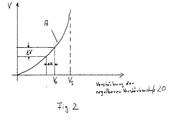
- the amplification V 0 of the controllable amplifier stage 20 is reduced by a first predetermined amount ⁇ a by activating the damping element with the aid of the pulse of the pulse pulse shaper 110 at predetermined time intervals for a predetermined period of time.
- the amount ⁇ a is entered in the diagram according to FIG. 2.
- the signal level changes at the output 60 of the amplifier 10, the change of which determines a level indicator 70, which on the output side can be connected to the monitoring and evaluation device 90, the amplification control device 80 and the pulse pulse shaper 110.
- Logarithmic integrated circuit solutions are available for level measurement in the level indicator 70. The conversion of its output signals into digital values enables the level indicator 70 and the monitoring and evaluation device 90 to be constructed in a favorable manner.
- the monitoring and evaluation device 90 determines the corresponding change ⁇ v in the gain V of the feedback amplifier 10. From the ratio ⁇ a / ⁇ v, the monitoring and evaluation device 110 can also determine the current oscillation distance V S / V 0 of the amplifier 10.
- the monitoring and evaluation device 90 can use a look-up table stored in a memory, which contains the associated oscillation distance V S / V 0 for each measured ratio ⁇ a / ⁇ v.
- the monitoring and evaluation device 90 now compares the determined current oscillation distance of the amplifier 10 with a previously stored oscillation distance. If the current oscillation distance is smaller than the preset oscillation distance, the gain V 0 of the controllable amplifier 10 is reduced by a predetermined amount, which corresponds to a lowering of the operating point of the amplifier. This ensures that the preset oscillation distance of the amplifier 10 is maintained. If, on the other hand, the monitoring and evaluation device 90 determines that the determined current oscillation distance is greater than the preset oscillation distance, then the amplification V 0 of the controllable amplifier stage 20 is increased by a predetermined amount, which corresponds to an increase in the operating point of the amplifier.
Landscapes
- Control Of Amplification And Gain Control (AREA)
- Monitoring And Testing Of Transmission In General (AREA)
- Amplifiers (AREA)
Abstract
Description
- Fig. 1
- ein Blockschaltbild eines adaptiven Repeaters gemäß der Erfindung, und
- Fig. 2
- ein Diagramm, bei dem die resultierende Verstärkung des Verstärkers 10 nach Fig. 1 über der Verstärkung der regelbaren Verstärkerstufe 20 aufgetragen ist.
In Fig. 2 ist eine Verstärkungskurve A des rückgekoppelten verstärkers 10 gemäß Gleichung (2) dargestellt, wobei die resultierende Verstärkung V des rückgekoppelten Verstärkers 10 über der Verstärkung der regelbaren Verstärkerstufe 20 des Verstärkers ist. Ferner ist der an der regelbaren Verstärkerstufe 20 voreingestellte Arbeitspunkt des Verstärkers 10 eingezeichnet, der bei der Verstärkung V0 liegt. Die kritische Verstärkung VS , bei der der Verstärker 10 in Schwingung gerät, bildet die senkrechte Asymptote für die Kurve A.
Claims (6)
- Schaltungsanordnung zum adaptiven Regeln der Verstärkung eines rückgekoppelten Verstärkers für digitale Signale nach der Patentanmeldung 197 52 283 miteinem Taktgeber (85), undeiner Überwachungs- und Auswerteeinrichtung (90), dadurch gekennzeichnet, daßdie Überwachungs- und Auswerteeinrichtung zum Überwachen und Auswerten einer Änderung des Signalpegels am Verstärkerausgang ausgebildet ist, daßeine Einrichtung (100) zum periodischen Ändern einer vorbestimmten Verstärkung (V0) des Verstärkers um einen ersten vorbestimmten Betrag (Δa) in vorbestimmten zeitlichen Abständen für jeweils eine vorbestimmte Zeitdauer undeine Einrichtung (20, 80) zum Anheben oder Absenken der vorbestimmten Verstärkung (V0) um einen zweiten vorbestimmten Betrag in Abhängigkeit der beim periodischen Ändern der vorbestimmten Verstärkung ausgewerteten Änderung des Signalpegels am Verstärkerausgang vorgesehen ist.
- Schaltungsanordnung nach Anspruch 1,
dadurch gekennzeichnet, daßein Speicher, der einen vorbestimmten Schwingabstand des Verstärkers speichert, mit der Überwachungs- und Auswerteeinrichtung (90) verbunden ist, und daßdie Überwachungs- und Auswerteeinrichtung aus der Änderung des Signalpegels am Verstärkerausgang in Abhängigkeit von der Änderung der vorbestimmten Verstärkung um den ersten vorbestimmten Betrag den aktuellen Schwingabstand des Verstärkers ermitteln und diesen mit dem gespeicherten Schwingabstand vergleichen kann. - Schaltungsanordnung nach Anspruch 1 oder 2,
dadurch gekennzeichnet, daßdie Einrichtung zum periodischen Ändern ein Dämpfungselement zum periodischen Absenken der vorbestimmten Verstärkung enthält. - Verfahren zum adaptiven Regeln der Verstärkung eines rückgekoppelten Verstärkers nach der Patentanmeldung 197 52 283 mit folgenden Verfahrensschritten:Voreinstellen der Verstärkung (V0) des Verstärkers;periodisches Ändern der voreingestellten Verstärkung (V0) um einen ersten vorbestimmten Betrag (Δa);Überwachen und Auswerten einer Änderung des Signalpegels am Verstärkerausgang während des periodischen Änderns der voreingestellten Verstärkung; undAnheben oder Absenken der voreingestellten Verstärkung (V0) um einen zweiten vorbestimmten Betrag in Abhängigkeit von der während des periodischen Änderns der vorbestimmten Verstärkung ausgewerteten Änderung des Signalpegels am Verstärkerausgang.
- Verfahren nach Anspruch 4,
dadurch gekennzeichnet, daß
der Schritt des Überwachens und Auswertens folgende weitere Verfahrensschritte umfasst:aus der Änderung des Signalpegels am Verstärkerausgang wird die entsprechende Verstärkungsänderung ( V) des rückgekoppelten Verstarkers ermittelt;Berechnen des aktuellen Schwingabstandes des Verstärkers aus der Verstärkungsänderung (ΔV) und der periodischen Änderung der voreingestellten Verstärkung (V0) um einen ersten vorbestimmten Betrag;Vergleichen des aktuellen Schwingabstandes mit einem vorbestimmten Schwingabstand. - Verfahren nach Anspruch 4 oder 5;
dadurch gekennzeichnet, daßdie voreingestellten Verstärkung (V0) um einen ersten vorbestimmten Betrag periodisch abgesenkt wird.
Applications Claiming Priority (2)
| Application Number | Priority Date | Filing Date | Title |
|---|---|---|---|
| DE1999123790 DE19923790A1 (de) | 1997-11-26 | 1999-05-25 | Schaltungsanordnung und Verfahren zum adaptiven Regeln der Verstärkung eines rückgekoppelten Verstärkers |
| DE19923790 | 1999-05-25 |
Publications (3)
| Publication Number | Publication Date |
|---|---|
| EP1056198A2 true EP1056198A2 (de) | 2000-11-29 |
| EP1056198A3 EP1056198A3 (de) | 2001-01-31 |
| EP1056198B1 EP1056198B1 (de) | 2005-04-27 |
Family
ID=7909043
Family Applications (1)
| Application Number | Title | Priority Date | Filing Date |
|---|---|---|---|
| EP00109851A Expired - Lifetime EP1056198B1 (de) | 1999-05-25 | 2000-05-10 | Schaltungsanordnung und Verfahren zum adaptiven Regeln der Verstärkung eines rückgekoppelten Verstärkers |
Country Status (3)
| Country | Link |
|---|---|
| EP (1) | EP1056198B1 (de) |
| AT (1) | ATE294463T1 (de) |
| DE (1) | DE50010141D1 (de) |
Family Cites Families (5)
| Publication number | Priority date | Publication date | Assignee | Title |
|---|---|---|---|---|
| DE3401748A1 (de) * | 1984-01-19 | 1985-08-01 | Siemens AG, 1000 Berlin und 8000 München | Schaltungsanordnung fuer eine digitale pegelregelung |
| US4776032A (en) * | 1985-05-15 | 1988-10-04 | Nippon Telegraph And Telephone Corporation | Repeater for a same frequency with spillover measurement |
| US5736901A (en) * | 1995-04-04 | 1998-04-07 | Matsushita Electric Industrial Co., Ltd. | Radio frequency amplifier with stable operation and restrained oscillation at low frequencies |
| GB9522198D0 (en) * | 1995-10-30 | 1996-01-03 | British Broadcasting Corp | Ofdm active deflectors |
| DE19752283C2 (de) * | 1997-11-26 | 2000-08-10 | Deutsche Telekom Ag | Schaltungsanordung und Verfahren zum adaptiven Regeln der Verstärkung eines rückgekoppelten Verstärkers für digitale Signale, insbesondere für ein digitales Rundfunksystem |
-
2000
- 2000-05-10 EP EP00109851A patent/EP1056198B1/de not_active Expired - Lifetime
- 2000-05-10 AT AT00109851T patent/ATE294463T1/de active
- 2000-05-10 DE DE50010141T patent/DE50010141D1/de not_active Expired - Lifetime
Also Published As
| Publication number | Publication date |
|---|---|
| ATE294463T1 (de) | 2005-05-15 |
| DE50010141D1 (de) | 2005-06-02 |
| EP1056198B1 (de) | 2005-04-27 |
| EP1056198A3 (de) | 2001-01-31 |
Similar Documents
| Publication | Publication Date | Title |
|---|---|---|
| DE69023611T2 (de) | Digitales Funkverbindungssystem und Verfahren zur Einstellung der Sendeleistung in einem digitalen Funkverbidungssystem. | |
| DE69112949T2 (de) | Gerät zur automatischen Leistungssteuerung. | |
| DE69701473T2 (de) | Verfahren und Vorrichtung zur Festlegung eines Arbeitspunktes eines nichtlinearen Verstärkers in einem Übertragungskanal | |
| DE69334001T2 (de) | Verfahren und Vorrichtung zur Übertragung von digitalen Datenpaketen auf einem drahtlosen Kanal | |
| EP1307975B1 (de) | Verfahren zur regelung der sendeleistung in einem funksystem | |
| EP0521342B1 (de) | Entzerrer für optische Nachrichtenübertragungssysteme | |
| EP1251646A2 (de) | Verfahren zur Halbduplexübertragung von Informationen zwischen Kommunikationseinrichtungen mit Repeatern | |
| DE102015217695B4 (de) | Kommunikationsvorrichtung mit Antennen-Dämpfungskompensation | |
| EP0521341A2 (de) | Entzerrer für optisch übertragene Nachrichtensignale | |
| DE3806864A1 (de) | Optisches uebertragungssystem | |
| DE10242700B4 (de) | Rückkopplungskompensator in einem akustischen Verstärkungssystem, Hörhilfsgerät, Verfahren zur Rückkopplungskompensation und Anwendung des Verfahrens in einem Hörhilfsgerät | |
| DE10031468B4 (de) | Fernbedienung | |
| DE3788398T2 (de) | Datenübertragungssystem mit Pegelsteuereinrichtung. | |
| DE102016208435B4 (de) | Fahrzeuginternes Netzwerksystem | |
| EP0920126B1 (de) | Verfahren und Vorrichtung zum adaptiven Regeln des Verstärkungsfaktors eines Verstärkers | |
| DE19830086A1 (de) | Software-gesteuertes Auswahl- und Testsystem | |
| EP1056198B1 (de) | Schaltungsanordnung und Verfahren zum adaptiven Regeln der Verstärkung eines rückgekoppelten Verstärkers | |
| DE19923790A1 (de) | Schaltungsanordnung und Verfahren zum adaptiven Regeln der Verstärkung eines rückgekoppelten Verstärkers | |
| DE3048978A1 (de) | Optisches datenuebertragungssystem | |
| DE69206918T2 (de) | Verfahren und einrichtung zur steuerung eines funksenders | |
| WO2003067784A1 (de) | Datenübertragungssystem mit einstellbarer sendeleistung | |
| DE19638129C2 (de) | Verfahren und Schaltungsanordnung zur Steuerung der Ausgangsleistung von Sendeendstufen | |
| DE69909728T2 (de) | Verfahren zur Sendeleistungsregelung | |
| EP0181314B1 (de) | Tunnelantennensystem zur breitbandigen Signalübertragung | |
| DE602004009153T2 (de) | Einrichtung und verfahren zur hochratigen optischen übertragung und verwendung der einrichtung des verfahrens |
Legal Events
| Date | Code | Title | Description |
|---|---|---|---|
| PUAI | Public reference made under article 153(3) epc to a published international application that has entered the european phase |
Free format text: ORIGINAL CODE: 0009012 |
|
| AK | Designated contracting states |
Kind code of ref document: A2 Designated state(s): AT BE CH CY DE DK ES FI FR GB GR IE IT LI LU MC NL PT SE |
|
| AX | Request for extension of the european patent |
Free format text: AL;LT;LV;MK;RO;SI |
|
| PUAL | Search report despatched |
Free format text: ORIGINAL CODE: 0009013 |
|
| RIC1 | Information provided on ipc code assigned before grant |
Free format text: 7H 03G 3/30 A, 7H 04B 7/26 B |
|
| AK | Designated contracting states |
Kind code of ref document: A3 Designated state(s): AT BE CH CY DE DK ES FI FR GB GR IE IT LI LU MC NL PT SE |
|
| AX | Request for extension of the european patent |
Free format text: AL;LT;LV;MK;RO;SI |
|
| 17P | Request for examination filed |
Effective date: 20010731 |
|
| AKX | Designation fees paid |
Free format text: AT BE CH CY DE DK ES FI FR GB GR IE IT LI LU MC NL PT SE |
|
| GRAP | Despatch of communication of intention to grant a patent |
Free format text: ORIGINAL CODE: EPIDOSNIGR1 |
|
| GRAS | Grant fee paid |
Free format text: ORIGINAL CODE: EPIDOSNIGR3 |
|
| GRAA | (expected) grant |
Free format text: ORIGINAL CODE: 0009210 |
|
| AK | Designated contracting states |
Kind code of ref document: B1 Designated state(s): AT BE CH CY DE DK ES FI FR GB GR IE IT LI LU MC NL PT SE |
|
| PG25 | Lapsed in a contracting state [announced via postgrant information from national office to epo] |
Ref country code: IT Free format text: LAPSE BECAUSE OF FAILURE TO SUBMIT A TRANSLATION OF THE DESCRIPTION OR TO PAY THE FEE WITHIN THE PRESCRIBED TIME-LIMIT;WARNING: LAPSES OF ITALIAN PATENTS WITH EFFECTIVE DATE BEFORE 2007 MAY HAVE OCCURRED AT ANY TIME BEFORE 2007. THE CORRECT EFFECTIVE DATE MAY BE DIFFERENT FROM THE ONE RECORDED. Effective date: 20050427 Ref country code: IE Free format text: LAPSE BECAUSE OF FAILURE TO SUBMIT A TRANSLATION OF THE DESCRIPTION OR TO PAY THE FEE WITHIN THE PRESCRIBED TIME-LIMIT Effective date: 20050427 Ref country code: FI Free format text: LAPSE BECAUSE OF FAILURE TO SUBMIT A TRANSLATION OF THE DESCRIPTION OR TO PAY THE FEE WITHIN THE PRESCRIBED TIME-LIMIT Effective date: 20050427 |
|
| REG | Reference to a national code |
Ref country code: GB Ref legal event code: FG4D Free format text: NOT ENGLISH |
|
| REG | Reference to a national code |
Ref country code: CH Ref legal event code: NV Representative=s name: ISLER & PEDRAZZINI AG Ref country code: CH Ref legal event code: EP |
|
| PG25 | Lapsed in a contracting state [announced via postgrant information from national office to epo] |
Ref country code: CY Free format text: LAPSE BECAUSE OF FAILURE TO SUBMIT A TRANSLATION OF THE DESCRIPTION OR TO PAY THE FEE WITHIN THE PRESCRIBED TIME-LIMIT Effective date: 20050510 Ref country code: LU Free format text: LAPSE BECAUSE OF NON-PAYMENT OF DUE FEES Effective date: 20050510 |
|
| REG | Reference to a national code |
Ref country code: IE Ref legal event code: FG4D Free format text: LANGUAGE OF EP DOCUMENT: GERMAN |
|
| PG25 | Lapsed in a contracting state [announced via postgrant information from national office to epo] |
Ref country code: MC Free format text: LAPSE BECAUSE OF NON-PAYMENT OF DUE FEES Effective date: 20050531 |
|
| REF | Corresponds to: |
Ref document number: 50010141 Country of ref document: DE Date of ref document: 20050602 Kind code of ref document: P |
|
| PG25 | Lapsed in a contracting state [announced via postgrant information from national office to epo] |
Ref country code: SE Free format text: LAPSE BECAUSE OF FAILURE TO SUBMIT A TRANSLATION OF THE DESCRIPTION OR TO PAY THE FEE WITHIN THE PRESCRIBED TIME-LIMIT Effective date: 20050727 Ref country code: GR Free format text: LAPSE BECAUSE OF FAILURE TO SUBMIT A TRANSLATION OF THE DESCRIPTION OR TO PAY THE FEE WITHIN THE PRESCRIBED TIME-LIMIT Effective date: 20050727 Ref country code: DK Free format text: LAPSE BECAUSE OF FAILURE TO SUBMIT A TRANSLATION OF THE DESCRIPTION OR TO PAY THE FEE WITHIN THE PRESCRIBED TIME-LIMIT Effective date: 20050727 |
|
| PG25 | Lapsed in a contracting state [announced via postgrant information from national office to epo] |
Ref country code: ES Free format text: LAPSE BECAUSE OF FAILURE TO SUBMIT A TRANSLATION OF THE DESCRIPTION OR TO PAY THE FEE WITHIN THE PRESCRIBED TIME-LIMIT Effective date: 20050807 |
|
| GBT | Gb: translation of ep patent filed (gb section 77(6)(a)/1977) |
Effective date: 20050714 |
|
| PG25 | Lapsed in a contracting state [announced via postgrant information from national office to epo] |
Ref country code: PT Free format text: LAPSE BECAUSE OF FAILURE TO SUBMIT A TRANSLATION OF THE DESCRIPTION OR TO PAY THE FEE WITHIN THE PRESCRIBED TIME-LIMIT Effective date: 20051010 |
|
| REG | Reference to a national code |
Ref country code: IE Ref legal event code: FD4D |
|
| PLBE | No opposition filed within time limit |
Free format text: ORIGINAL CODE: 0009261 |
|
| STAA | Information on the status of an ep patent application or granted ep patent |
Free format text: STATUS: NO OPPOSITION FILED WITHIN TIME LIMIT |
|
| ET | Fr: translation filed | ||
| 26N | No opposition filed |
Effective date: 20060130 |
|
| REG | Reference to a national code |
Ref country code: CH Ref legal event code: PCAR Free format text: ISLER & PEDRAZZINI AG;POSTFACH 1772;8027 ZUERICH (CH) |
|
| PGFP | Annual fee paid to national office [announced via postgrant information from national office to epo] |
Ref country code: FR Payment date: 20110603 Year of fee payment: 12 Ref country code: CH Payment date: 20110525 Year of fee payment: 12 |
|
| PGFP | Annual fee paid to national office [announced via postgrant information from national office to epo] |
Ref country code: AT Payment date: 20110520 Year of fee payment: 12 Ref country code: GB Payment date: 20110523 Year of fee payment: 12 Ref country code: BE Payment date: 20110525 Year of fee payment: 12 Ref country code: NL Payment date: 20110524 Year of fee payment: 12 |
|
| PGFP | Annual fee paid to national office [announced via postgrant information from national office to epo] |
Ref country code: DE Payment date: 20110720 Year of fee payment: 12 |
|
| BERE | Be: lapsed |
Owner name: DEUTSCHE *TELEKOM A.G. Effective date: 20120531 |
|
| REG | Reference to a national code |
Ref country code: NL Ref legal event code: V1 Effective date: 20121201 |
|
| REG | Reference to a national code |
Ref country code: CH Ref legal event code: PL |
|
| REG | Reference to a national code |
Ref country code: AT Ref legal event code: MM01 Ref document number: 294463 Country of ref document: AT Kind code of ref document: T Effective date: 20120510 |
|
| GBPC | Gb: european patent ceased through non-payment of renewal fee |
Effective date: 20120510 |
|
| PG25 | Lapsed in a contracting state [announced via postgrant information from national office to epo] |
Ref country code: AT Free format text: LAPSE BECAUSE OF NON-PAYMENT OF DUE FEES Effective date: 20120510 Ref country code: CH Free format text: LAPSE BECAUSE OF NON-PAYMENT OF DUE FEES Effective date: 20120531 Ref country code: LI Free format text: LAPSE BECAUSE OF NON-PAYMENT OF DUE FEES Effective date: 20120531 |
|
| PG25 | Lapsed in a contracting state [announced via postgrant information from national office to epo] |
Ref country code: BE Free format text: LAPSE BECAUSE OF NON-PAYMENT OF DUE FEES Effective date: 20120531 |
|
| REG | Reference to a national code |
Ref country code: FR Ref legal event code: ST Effective date: 20130131 |
|
| REG | Reference to a national code |
Ref country code: DE Ref legal event code: R119 Ref document number: 50010141 Country of ref document: DE Effective date: 20121201 |
|
| PG25 | Lapsed in a contracting state [announced via postgrant information from national office to epo] |
Ref country code: NL Free format text: LAPSE BECAUSE OF NON-PAYMENT OF DUE FEES Effective date: 20121201 |
|
| PG25 | Lapsed in a contracting state [announced via postgrant information from national office to epo] |
Ref country code: GB Free format text: LAPSE BECAUSE OF NON-PAYMENT OF DUE FEES Effective date: 20120510 Ref country code: FR Free format text: LAPSE BECAUSE OF NON-PAYMENT OF DUE FEES Effective date: 20120531 |
|
| PG25 | Lapsed in a contracting state [announced via postgrant information from national office to epo] |
Ref country code: DE Free format text: LAPSE BECAUSE OF NON-PAYMENT OF DUE FEES Effective date: 20121201 |