EP1056104A1 - High-speed control device for a high voltage connection apparatus, in particular a grounding disconnector - Google Patents
High-speed control device for a high voltage connection apparatus, in particular a grounding disconnector Download PDFInfo
- Publication number
- EP1056104A1 EP1056104A1 EP00401498A EP00401498A EP1056104A1 EP 1056104 A1 EP1056104 A1 EP 1056104A1 EP 00401498 A EP00401498 A EP 00401498A EP 00401498 A EP00401498 A EP 00401498A EP 1056104 A1 EP1056104 A1 EP 1056104A1
- Authority
- EP
- European Patent Office
- Prior art keywords
- spring
- movable contact
- link
- integral
- occupies
- Prior art date
- Legal status (The legal status is an assumption and is not a legal conclusion. Google has not performed a legal analysis and makes no representation as to the accuracy of the status listed.)
- Granted
Links
Images
Classifications
-
- H—ELECTRICITY
- H01—ELECTRIC ELEMENTS
- H01H—ELECTRIC SWITCHES; RELAYS; SELECTORS; EMERGENCY PROTECTIVE DEVICES
- H01H3/00—Mechanisms for operating contacts
- H01H3/60—Mechanical arrangements for preventing or damping vibration or shock
-
- H—ELECTRICITY
- H01—ELECTRIC ELEMENTS
- H01H—ELECTRIC SWITCHES; RELAYS; SELECTORS; EMERGENCY PROTECTIVE DEVICES
- H01H3/00—Mechanisms for operating contacts
- H01H3/22—Power arrangements internal to the switch for operating the driving mechanism
- H01H3/30—Power arrangements internal to the switch for operating the driving mechanism using spring motor
-
- H—ELECTRICITY
- H01—ELECTRIC ELEMENTS
- H01H—ELECTRIC SWITCHES; RELAYS; SELECTORS; EMERGENCY PROTECTIVE DEVICES
- H01H3/00—Mechanisms for operating contacts
- H01H3/32—Driving mechanisms, i.e. for transmitting driving force to the contacts
- H01H3/36—Driving mechanisms, i.e. for transmitting driving force to the contacts using belt, chain, or cord
-
- H—ELECTRICITY
- H01—ELECTRIC ELEMENTS
- H01H—ELECTRIC SWITCHES; RELAYS; SELECTORS; EMERGENCY PROTECTIVE DEVICES
- H01H3/00—Mechanisms for operating contacts
- H01H3/60—Mechanical arrangements for preventing or damping vibration or shock
- H01H3/605—Mechanical arrangements for preventing or damping vibration or shock making use of a fluid damper
Definitions
- the present invention relates to a rapid control device for a high voltage connection device, in particular an earthing switch, equipped with a movable contact comprising an energy storage spring mechanical, a mechanism for arming this spring comprising a motor electric arranged to drive at least one rotary part arranged to occupy two stable positions corresponding respectively to the armed spring and to the disarmed spring, this arming mechanism being provided with a link coupled to a mechanism for controlling a movable contact, this link being associated with a brake damping device acting as a stop for said rod in the positions it occupies when said rotary part occupies said two stable positions.
- a device of this type is known from the published French patent application under the number 2 766 961.
- a single shock absorber consisting for example a rubber stop housed in a cylindrical sleeve and rigidly mounted in the device housing, cooperates with a link coupled to the control mechanism of a movable contact to stop this rod in its two stable positions and to absorb the shocks which result.
- the object of the present invention is to overcome the drawbacks of the art by making a device for which the damping of the link coupled to the mobile contact control mechanism is carried out efficiently and economically satisfactory.
- a device as described in the preamble characterized in that said brake damping device comprises at least one damper hydraulic mounted on a fixed support secured to the device housing by through a spring organ.
- This spring organ has the function of contribute to the absorption of the shocks received during the arrival of the stop said link. Therefore, the fixing of the shock absorber itself and the stability of its mounting on its support inside the housing of the device are made safe and reliable.
- said spring member comprises at least a stack of Belleville washers.
- Such a known spring member is particularly robust while being economical.
- said brake damping device has two hydraulic shock absorbers arranged in parallel and arranged to operate respectively as a stop for said link when the latter occupies its positions corresponding to the two stable positions of said rotating part.
- This type of standard commercial shock absorbers is particularly economical and resistant, which meets the requirements required.
- said mechanism for actuating a movable contact comprises a pivoting lever articulated on said link, this lever pivoting being integral with a control axis of said movable contact and carrying two support protrusions arranged to cooperate respectively with two piston rods of the two hydraulic shock absorbers.
- Said protuberances are preferably arranged on an arm integral with the control axis of said movable contact.
- said arm carrying said protrusions is advantageously mounted symmetrically with respect to the control axis of said mobile contact.
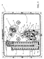
- the device 10 quick control for high voltage connection device, and in particular for an earthing switch, equipped with a movable contact, such as shown, includes a spring 11 for accumulating mechanical energy, a arming mechanism 12 of this spring comprising an electric motor arranged to drive at least one rotary part 13 arranged to occupy two stable positions corresponding respectively to the armed spring and the disarmed spring, this arming mechanism 12 being provided with a rod 14 coupled to an actuating mechanism 15 of a movable contact.
- the rod 14 is associated with a brake damping device 16 acting as a stop for said link in the positions it occupies when said piece rotary 13 occupies said two stable positions.
- the damping device brake 16 comprises at least one hydraulic damper 17, respectively 18, mounted on a fixed support integral with the housing of the device via of a spring member 19, respectively 20.
- the spring 11 housed in a cylindrical sleeve 11a, including the movable bottom 11b coupled to a chain 11c connected by a rod 11d to a part 12a which is articulated on said rotary part 13, is described in detail, as well as all associated components, in the publication mentioned above and illustrating prior art.
- the actuating mechanism 15, associated with the link 14, comprises a lever 15a which is pivotally mounted on the control axis 15b of said movable contact (not shown).
- This lever is articulated at a point 15c on the link 14.
- It also includes an arm 15d, integral with this lever or rigidly fixed to the control axis 15b, this arm being mounted symmetrically with respect to the axis 15b and carrying at its ends two support protrusions 15e and 15f.
- the support protrusions 15e and 15f are arranged to cooperate respectively with the piston rods of two hydraulic shock absorbers 17 and 18 of the brake damping device 16.
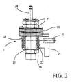
- a hydraulic damper 17 or 18 of the brake damper device 16 is represented by FIG. 2. It comprises a threaded body 21 of cylindrical shape screwed into a cylindrical socket 22, surmounted by the spring member 20, consisting of a stack of Belleville washers.
- the cylindrical socket 22 is engaged in a bore 23 of a support 24 in the form of a bracket, secured to the device housing by a pin 25 or any other suitable fixing means.
- a nut 26 makes the threaded body 21 of the shock absorber integral with the cylindrical sleeve 22.
- a double nut 27 blocks the stack of Belleville washers against the bush 22 and in abutment the support 24.
- a piston rod 28, extending axially from the body of the damper is arranged to cooperate with the protrusion 15f.
- the present invention is not limited to the embodiment described, but may undergo various variations or modifications obvious to a person job.
Abstract
Description
La présente invention concerne un dispositif de commande rapide pour un appareil de connexion à haute tension, notamment un sectionneur de terre, équipé d'un contact mobile comportant un ressort d'accumulation d'énergie mécanique, un mécanisme d'armement de ce ressort comprenant un moteur électrique agencé pour entraíner au moins une pièce rotative agencée pour occuper deux positions stables correspondant respectivement au ressort armé et au ressort désarmé, ce mécanisme d'armement étant pourvu d'une biellette couplée à un mécanisme de commande d'un contact mobile, cette biellette étant associée à un dispositif amortisseur frein agissant comme une butée pour ladite biellette dans les positions qu'elle occupe lorsque ladite pièce rotative occupe lesdites deux positions stables.The present invention relates to a rapid control device for a high voltage connection device, in particular an earthing switch, equipped with a movable contact comprising an energy storage spring mechanical, a mechanism for arming this spring comprising a motor electric arranged to drive at least one rotary part arranged to occupy two stable positions corresponding respectively to the armed spring and to the disarmed spring, this arming mechanism being provided with a link coupled to a mechanism for controlling a movable contact, this link being associated with a brake damping device acting as a stop for said rod in the positions it occupies when said rotary part occupies said two stable positions.
Un dispositif de ce type est connu par la demande de brevet français publiée sous le numéro 2 766 961. Sur ce dispositif un amortisseur unique, constitué par exemple d'une butée en caoutchouc logée dans une douille cylindrique et montée rigidement dans le boítier du dispositif, coopère avec une biellette couplée au mécanisme de commande d'un contact mobile pour arrêter cette biellette dans ses deux positions stables et pour amortir les chocs qui en résultent.A device of this type is known from the published French patent application under the number 2 766 961. On this device a single shock absorber, consisting for example a rubber stop housed in a cylindrical sleeve and rigidly mounted in the device housing, cooperates with a link coupled to the control mechanism of a movable contact to stop this rod in its two stable positions and to absorb the shocks which result.
Ce dispositif ne donne pas entière satisfaction en ce qui concerne l'amortisseur qui subit des chocs violents en absorbant brutalement les décélérations de la biellette.This device is not entirely satisfactory with regard to the shock absorber who is subjected to violent shocks by brutally absorbing the decelerations of the link.
Le but de la présente invention est de pallier les inconvénients de l'art antérieur en réalisant un dispositif pour lequel l'amortissement de la biellette couplée au mécanisme de commande du contact mobile s'effectue de manière efficace et économiquement satisfaisante. The object of the present invention is to overcome the drawbacks of the art by making a device for which the damping of the link coupled to the mobile contact control mechanism is carried out efficiently and economically satisfactory.
Ce but est atteint par un dispositif tel que décrit en préambule, caractérisé en ce que ledit dispositif amortisseur frein comporte au moins un amortisseur hydraulique monté sur un support fixe solidaire du boítier du dispositif par l'intermédiaire d'un organe ressort. Cet organe ressort a pour fonction de contribuer à l'amortissement des chocs encaissés lors de l'arrivée en butée de ladite biellette. De ce fait, la fixation de l'amortisseur proprement dit et la stabilité de son montage sur son support à l'intérieur du boítier du dispositif sont rendus sûrs et fiables.This object is achieved by a device as described in the preamble, characterized in that said brake damping device comprises at least one damper hydraulic mounted on a fixed support secured to the device housing by through a spring organ. This spring organ has the function of contribute to the absorption of the shocks received during the arrival of the stop said link. Therefore, the fixing of the shock absorber itself and the stability of its mounting on its support inside the housing of the device are made safe and reliable.
Selon un mode de réalisation préféré, ledit organe ressort comporte au moins un empilement de rondelles de Belleville. Un tel organe ressort connu est particulièrement robuste tout en étant économique.According to a preferred embodiment, said spring member comprises at least a stack of Belleville washers. Such a known spring member is particularly robust while being economical.
Selon un mode de réalisation avantageux, ledit dispositif amortisseur frein comporte deux amortisseurs hydrauliques disposés parallèlement et agencés pour opérer respectivement comme butée pour ladite biellette lorsque celle-ci occupe ses positions correspondant aux deux positions stables de ladite pièce rotative. Ce type d'amortisseurs standards du commerce est particulièrement économique et résistant, ce qui correspond aux exigences requises.According to an advantageous embodiment, said brake damping device has two hydraulic shock absorbers arranged in parallel and arranged to operate respectively as a stop for said link when the latter occupies its positions corresponding to the two stable positions of said rotating part. This type of standard commercial shock absorbers is particularly economical and resistant, which meets the requirements required.
Selon une forme de réalisation préférée, ledit mécanisme d'actionnement d'un contact mobile comporte un levier pivotant articulé sur ladite biellette, ce levier pivotant étant solidaire d'un axe de commande dudit contact mobile et portant deux protubérances d'appui agencées pour coopérer respectivement avec deux tiges de piston des deux amortisseurs hydrauliques.According to a preferred embodiment, said mechanism for actuating a movable contact comprises a pivoting lever articulated on said link, this lever pivoting being integral with a control axis of said movable contact and carrying two support protrusions arranged to cooperate respectively with two piston rods of the two hydraulic shock absorbers.
Lesdites protubérances sont de préférence disposées sur un bras solidaire de l'axe de commande dudit contact mobile. Said protuberances are preferably arranged on an arm integral with the control axis of said movable contact.
De façon avantageuse, ledit bras portant lesdites protubérances est avantageusement monté symétriquement par rapport à l'axe de commande dudit contact mobile.Advantageously, said arm carrying said protrusions is advantageously mounted symmetrically with respect to the control axis of said mobile contact.
La présente invention et ses avantages seront mieux compris en référence à la description d'une forme de réalisation préférée du dispositif selon l'invention et aux dessins annexés, donnés à titre d'exemple non limitatif, dans lesquels :
- la figure 1 est une vue en coupe illustrant les principaux composants du dispositif selon l'invention, et
- la figure 2 est une vue en coupe axiale d'un amortisseur monté dans le dispositif de l'invention.
- FIG. 1 is a sectional view illustrating the main components of the device according to the invention, and
- Figure 2 is an axial sectional view of a damper mounted in the device of the invention.
En référence aux figures, et plus particulièrement à la figure 1, le dispositif 10
de commande rapide pour appareil de connexion à haute tension, et
notamment pour un sectionneur de terre, équipé d'un contact mobile, tel que
représenté, comporte un ressort 11 d'accumulation d'énergie mécanique, un
mécanisme d'armement 12 de ce ressort comprenant un moteur électrique
agencé pour entraíner au moins une pièce rotative 13 agencée pour occuper
deux positions stables correspondant respectivement au ressort armé et au
ressort désarmé, ce mécanisme d'armement 12 étant pourvu d'une biellette 14
couplée à un mécanisme d'actionnement 15 d'un contact mobile. La biellette 14
est associée à un dispositif amortisseur frein 16 agissant comme une butée
pour ladite biellette dans les positions qu'elle occupe lorsque ladite pièce
rotative 13 occupe lesdites deux positions stables. Le dispositif amortisseur
frein 16 comporte au moins un amortisseur hydraulique 17, respectivement 18,
monté sur un support fixe solidaire du boítier du dispositif par l'intermédiaire
d'un organe ressort 19, respectivement 20.With reference to the figures, and more particularly to FIG. 1, the
Le ressort 11 logé dans une douille cylindrique 11a, dont le fond mobile 11b
couplé à une chaíne 11c reliée par une tige 11d à une pièce 12a qui est
articulée sur ladite pièce rotative 13, est décrite en détail, ainsi que tous les
composants associés, dans la publication mentionnée ci-dessus et illustrant
l'art antérieur.The
Le mécanisme d'actionnement 15, associé à la biellette 14, comporte un levier
15a qui est monté pivotant sur l'axe de commande 15b dudit contact mobile
(non représenté). Ce levier est articulé en un point 15c sur la biellette 14. Il
comporte par ailleurs un bras 15d, solidaire de ce levier ou rigidement fixé sur
l'axe de commande 15b, ce bras étant monté symétriquement par rapport à
l'axe 15b et portant à ses extrémités deux protubérances d'appui 15e et 15f.
Les protubérances d'appui 15e et 15f sont agencées pour coopérer
respectivement avec les tiges de piston de deux amortisseurs hydrauliques 17
et 18 du dispositif amortisseur frein16.The
Un amortisseur hydraulique 17 ou 18 du dispositif amortisseur frein 16 est
représenté par la figure 2. Il comporte un corps fileté 21 de forme cylindrique
vissé dans une douille cylindrique 22, surmonté par l'organe ressort 20,
constitué d'un empilement de rondelles de Belleville. La douille cylindrique 22
est engagée dans un alésage 23 d'un support 24 en forme de potence,
rendue solidaire du boítier du dispositif par une goupille 25 ou tout autre
moyen de fixation approprié. Un écrou 26 rend le corps fileté 21 de
l'amortisseur solidaire de la douille cylindrique 22. Un double écrou 27 bloque
l'empilement de rondelles de Belleville contre la douille 22 et en appui contre
le support 24. Une tige de piston 28, sortant axialement du corps de
l'amortisseur, est agencée pour coopérer avec la protubérance 15f.A
Grâce à ce montage, les chocs dus à la mise en contact brutal des
protubérances 15e et 15f avec les tiges de piston des amortisseurs
hydrauliques 17 et 18, sont doublement amortis, une première fois par les
rondelles de Belleville et une deuxième fois par les pistons des amortisseurs
hydrauliques eux-mêmes. Thanks to this arrangement, the shocks due to the brutal contacting of
La présente invention n'est pas limitée à la forme de réalisation décrite, mais peut subir diverses variantes ou modifications évidentes pour l'homme du métier.The present invention is not limited to the embodiment described, but may undergo various variations or modifications obvious to a person job.
Claims (6)
Applications Claiming Priority (2)
| Application Number | Priority Date | Filing Date | Title |
|---|---|---|---|
| FR9907114 | 1999-05-28 | ||
| FR9907114A FR2794278B1 (en) | 1999-05-28 | 1999-05-28 | QUICK CONTROL DEVICE FOR A HIGH VOLTAGE CONNECTION APPARATUS, IN PARTICULAR AN EARTH ISOLATOR |
Publications (2)
| Publication Number | Publication Date |
|---|---|
| EP1056104A1 true EP1056104A1 (en) | 2000-11-29 |
| EP1056104B1 EP1056104B1 (en) | 2006-07-19 |
Family
ID=9546423
Family Applications (1)
| Application Number | Title | Priority Date | Filing Date |
|---|---|---|---|
| EP00401498A Expired - Lifetime EP1056104B1 (en) | 1999-05-28 | 2000-05-16 | High-speed control device for a high voltage connection apparatus, in particular a grounding disconnector |
Country Status (7)
| Country | Link |
|---|---|
| US (1) | US6355898B1 (en) |
| EP (1) | EP1056104B1 (en) |
| JP (1) | JP2000353459A (en) |
| AT (1) | ATE333704T1 (en) |
| CA (1) | CA2309794A1 (en) |
| DE (1) | DE60029386T2 (en) |
| FR (1) | FR2794278B1 (en) |
Cited By (3)
| Publication number | Priority date | Publication date | Assignee | Title |
|---|---|---|---|---|
| WO2002044585A1 (en) * | 2000-11-30 | 2002-06-06 | Siemens Aktiengesellschaft | Switch mechanism |
| WO2010003589A1 (en) * | 2008-07-08 | 2010-01-14 | Abb Technology Ag | Hydraulic stored-energy spring mechanism |
| CN103441016A (en) * | 2013-08-30 | 2013-12-11 | 石家庄八五零电子有限公司 | Power type microswitch |
Families Citing this family (7)
| Publication number | Priority date | Publication date | Assignee | Title |
|---|---|---|---|---|
| CN100356492C (en) * | 2005-03-23 | 2007-12-19 | 王光顺 | Energy-storage isolating switch |
| US7633364B2 (en) * | 2006-03-14 | 2009-12-15 | Eaton Corporation | Dampening apparatus and circuit interrupter including the same |
| FR2907596B1 (en) * | 2006-10-18 | 2009-01-23 | Areva T & D Sa | DEVICE FOR CONTROLLING AN ELECTRICAL EQUIPMENT |
| US8058580B2 (en) * | 2009-09-16 | 2011-11-15 | Eaton Corporation | Electrical switching apparatus and linking assembly therefor |
| KR200475886Y1 (en) | 2010-12-29 | 2015-01-09 | 엘에스산전 주식회사 | Spring housing unit of motor spring operator |
| CN102360983B (en) * | 2011-09-30 | 2014-01-01 | 福州天一同益电气有限公司 | Circuit breaker control device |
| KR101336337B1 (en) | 2011-10-20 | 2013-12-06 | 원신이엔지(주) | DC power short-circuit switch |
Citations (7)
| Publication number | Priority date | Publication date | Assignee | Title |
|---|---|---|---|---|
| DE2603536A1 (en) * | 1976-01-29 | 1977-08-11 | Siemens Ag | HV switchgear drive with energy storage unit - has movable support with piston in fixed cylinder with spring and retainer |
| DE3402948A1 (en) * | 1983-02-16 | 1984-08-16 | Mitsubishi Denki K.K., Tokio/Tokyo | Attachment device for electrical devices |
| DE3540674A1 (en) * | 1985-11-16 | 1987-05-21 | Licentia Gmbh | Motor/spring force drive system for a high-voltage circuit breaker |
| DE3608934A1 (en) * | 1986-03-18 | 1987-09-24 | Fichtel & Sachs Ag | Suspension system for a motor vehicle |
| EP0558115A1 (en) * | 1992-02-24 | 1993-09-01 | General Motors Corporation | Uppper mount assembly for a suspension damper |
| DE4446664C1 (en) * | 1994-12-16 | 1996-03-07 | Siemens Ag | Spring drive for electric load switch |
| FR2766961A1 (en) * | 1997-07-31 | 1999-02-05 | Gec Alsthom T & D Ag | High voltage fast isolating switch control device |
Family Cites Families (4)
| Publication number | Priority date | Publication date | Assignee | Title |
|---|---|---|---|---|
| GB1578740A (en) * | 1978-03-30 | 1980-11-05 | Northern Eng Ind | High-voltage circuit breakers |
| FR2609839B1 (en) * | 1987-01-21 | 1989-04-07 | Merlin Gerin | MECHANISM FOR HANGING THE CONTROL OF A THREE-POSITION CIRCUIT BREAKER |
| DE59007411D1 (en) * | 1989-03-03 | 1994-11-17 | Gec Alsthom T & D Ag | Spring drive for a circuit breaker. |
| US4915354A (en) * | 1989-04-10 | 1990-04-10 | Colt Industries Inc. | Cushioned valve seat |
-
1999
- 1999-05-28 FR FR9907114A patent/FR2794278B1/en not_active Expired - Fee Related
-
2000
- 2000-05-16 EP EP00401498A patent/EP1056104B1/en not_active Expired - Lifetime
- 2000-05-16 AT AT00401498T patent/ATE333704T1/en not_active IP Right Cessation
- 2000-05-16 DE DE60029386T patent/DE60029386T2/en not_active Expired - Lifetime
- 2000-05-25 US US09/577,599 patent/US6355898B1/en not_active Expired - Fee Related
- 2000-05-26 JP JP2000155802A patent/JP2000353459A/en not_active Withdrawn
- 2000-05-26 CA CA002309794A patent/CA2309794A1/en not_active Abandoned
Patent Citations (7)
| Publication number | Priority date | Publication date | Assignee | Title |
|---|---|---|---|---|
| DE2603536A1 (en) * | 1976-01-29 | 1977-08-11 | Siemens Ag | HV switchgear drive with energy storage unit - has movable support with piston in fixed cylinder with spring and retainer |
| DE3402948A1 (en) * | 1983-02-16 | 1984-08-16 | Mitsubishi Denki K.K., Tokio/Tokyo | Attachment device for electrical devices |
| DE3540674A1 (en) * | 1985-11-16 | 1987-05-21 | Licentia Gmbh | Motor/spring force drive system for a high-voltage circuit breaker |
| DE3608934A1 (en) * | 1986-03-18 | 1987-09-24 | Fichtel & Sachs Ag | Suspension system for a motor vehicle |
| EP0558115A1 (en) * | 1992-02-24 | 1993-09-01 | General Motors Corporation | Uppper mount assembly for a suspension damper |
| DE4446664C1 (en) * | 1994-12-16 | 1996-03-07 | Siemens Ag | Spring drive for electric load switch |
| FR2766961A1 (en) * | 1997-07-31 | 1999-02-05 | Gec Alsthom T & D Ag | High voltage fast isolating switch control device |
Cited By (4)
| Publication number | Priority date | Publication date | Assignee | Title |
|---|---|---|---|---|
| WO2002044585A1 (en) * | 2000-11-30 | 2002-06-06 | Siemens Aktiengesellschaft | Switch mechanism |
| WO2010003589A1 (en) * | 2008-07-08 | 2010-01-14 | Abb Technology Ag | Hydraulic stored-energy spring mechanism |
| CN103441016A (en) * | 2013-08-30 | 2013-12-11 | 石家庄八五零电子有限公司 | Power type microswitch |
| CN103441016B (en) * | 2013-08-30 | 2015-09-09 | 石家庄八五零电子有限公司 | A kind of power type microswitch |
Also Published As
| Publication number | Publication date |
|---|---|
| CA2309794A1 (en) | 2000-11-28 |
| ATE333704T1 (en) | 2006-08-15 |
| JP2000353459A (en) | 2000-12-19 |
| FR2794278B1 (en) | 2001-08-10 |
| DE60029386T2 (en) | 2007-07-12 |
| FR2794278A1 (en) | 2000-12-01 |
| US6355898B1 (en) | 2002-03-12 |
| DE60029386D1 (en) | 2006-08-31 |
| EP1056104B1 (en) | 2006-07-19 |
Similar Documents
| Publication | Publication Date | Title |
|---|---|---|
| EP1056104B1 (en) | High-speed control device for a high voltage connection apparatus, in particular a grounding disconnector | |
| EP0696039B1 (en) | Circuit breaker mechanism provided with an energy accumulator with a damping stop | |
| FR2565649A1 (en) | Adjustable stop with a spring, especially for car bodywork. | |
| EP0604272B1 (en) | Vehicle window regulator with shock absorbing antisqueeze safety device | |
| FR2683383A1 (en) | HIGH OR MEDIUM VOLTAGE CIRCUIT BREAKER WITH TRIPLE MOTION. | |
| KR102509492B1 (en) | Pedal device with shock absorber of drive | |
| FR2594774A1 (en) | BRAKING SYSTEM FOR VEHICLES | |
| FR2594766A1 (en) | WIPER FOR VEHICLES | |
| EP0603085A1 (en) | Windscreen wiper with rotation damper, especially for motorvehicles | |
| FR2610259A1 (en) | DEVICE FOR CONTROLLING A COUPLING MEANS SUCH AS FOR EXAMPLE A CLUTCH | |
| EP1130610B1 (en) | Device for operating mechanism of an electrical apparatus and operating mechanism with such a device | |
| EP0053528A1 (en) | Brake pressure proportioning valve | |
| EP0008247B1 (en) | Electric window-raising device | |
| FR2520312A1 (en) | HYDROMECHANICAL CONTROL CONTACTOR FOR REMOTE LIGHTING ADJUSTMENT SYSTEM OF MOTOR VEHICLE HEADLIGHTS | |
| FR2673247A1 (en) | STARTER OF INTERNAL COMBUSTION ENGINE, PARTICULARLY, STARTER OF MOTOR VEHICLE. | |
| FR2635845A1 (en) | Locking clutch for transmission with a hydraulic coupling member | |
| EP0012046A1 (en) | Electrical starting motor for internal combustion engines, particularly for automotive vehicles | |
| EP0851334A1 (en) | Operating lever for a vibration-resistant device | |
| WO1979000601A1 (en) | Shock absorbing stop mechanism | |
| RU97102121A (en) | DEVICE FOR AUTOMATIC STARTING OF FIRE EXTINGUISHING INSTALLATIONS | |
| FR2610262A1 (en) | Device for the motorised control of a coupling means, such as a clutch for example | |
| FR2583352A1 (en) | Bowden cable-operated vehicle sunroof | |
| FR2398893A1 (en) | IMPROVEMENTS TO THE CONTROL LEVERS OF THE LAUNCHER OF AN ELECTRIC STARTER | |
| SU956860A1 (en) | Torsion spring | |
| FR2823544A1 (en) | ELECTRIC ACTUATOR WITH COMPACT COMPENSATION SYSTEM, PARTICULARLY FOR CLUTCH OR TRANSMISSION CONTROL ON A ROBOTIC GEARBOX |
Legal Events
| Date | Code | Title | Description |
|---|---|---|---|
| PUAI | Public reference made under article 153(3) epc to a published international application that has entered the european phase |
Free format text: ORIGINAL CODE: 0009012 |
|
| AK | Designated contracting states |
Kind code of ref document: A1 Designated state(s): AT BE CH CY DE DK ES FI FR GB GR IE IT LI LU MC NL PT SE |
|
| AX | Request for extension of the european patent |
Free format text: AL;LT;LV;MK;RO;SI |
|
| 17P | Request for examination filed |
Effective date: 20010529 |
|
| AKX | Designation fees paid |
Free format text: AT BE CH CY DE DK ES FI FR GB GR IE IT LI LU MC NL PT SE |
|
| GRAP | Despatch of communication of intention to grant a patent |
Free format text: ORIGINAL CODE: EPIDOSNIGR1 |
|
| RAP1 | Party data changed (applicant data changed or rights of an application transferred) |
Owner name: AREVA T&D SA |
|
| GRAS | Grant fee paid |
Free format text: ORIGINAL CODE: EPIDOSNIGR3 |
|
| GRAA | (expected) grant |
Free format text: ORIGINAL CODE: 0009210 |
|
| AK | Designated contracting states |
Kind code of ref document: B1 Designated state(s): AT BE CH CY DE DK ES FI FR GB GR IE IT LI LU MC NL PT SE |
|
| PG25 | Lapsed in a contracting state [announced via postgrant information from national office to epo] |
Ref country code: IT Free format text: LAPSE BECAUSE OF FAILURE TO SUBMIT A TRANSLATION OF THE DESCRIPTION OR TO PAY THE FEE WITHIN THE PRESCRIBED TIME-LIMIT;WARNING: LAPSES OF ITALIAN PATENTS WITH EFFECTIVE DATE BEFORE 2007 MAY HAVE OCCURRED AT ANY TIME BEFORE 2007. THE CORRECT EFFECTIVE DATE MAY BE DIFFERENT FROM THE ONE RECORDED. Effective date: 20060719 Ref country code: GB Free format text: LAPSE BECAUSE OF FAILURE TO SUBMIT A TRANSLATION OF THE DESCRIPTION OR TO PAY THE FEE WITHIN THE PRESCRIBED TIME-LIMIT Effective date: 20060719 Ref country code: IE Free format text: LAPSE BECAUSE OF FAILURE TO SUBMIT A TRANSLATION OF THE DESCRIPTION OR TO PAY THE FEE WITHIN THE PRESCRIBED TIME-LIMIT Effective date: 20060719 Ref country code: NL Free format text: LAPSE BECAUSE OF FAILURE TO SUBMIT A TRANSLATION OF THE DESCRIPTION OR TO PAY THE FEE WITHIN THE PRESCRIBED TIME-LIMIT Effective date: 20060719 Ref country code: AT Free format text: LAPSE BECAUSE OF FAILURE TO SUBMIT A TRANSLATION OF THE DESCRIPTION OR TO PAY THE FEE WITHIN THE PRESCRIBED TIME-LIMIT Effective date: 20060719 Ref country code: FI Free format text: LAPSE BECAUSE OF FAILURE TO SUBMIT A TRANSLATION OF THE DESCRIPTION OR TO PAY THE FEE WITHIN THE PRESCRIBED TIME-LIMIT Effective date: 20060719 |
|
| REG | Reference to a national code |
Ref country code: GB Ref legal event code: FG4D Free format text: NOT ENGLISH |
|
| REG | Reference to a national code |
Ref country code: CH Ref legal event code: EP |
|
| REG | Reference to a national code |
Ref country code: IE Ref legal event code: FG4D Free format text: LANGUAGE OF EP DOCUMENT: FRENCH |
|
| REF | Corresponds to: |
Ref document number: 60029386 Country of ref document: DE Date of ref document: 20060831 Kind code of ref document: P |
|
| PG25 | Lapsed in a contracting state [announced via postgrant information from national office to epo] |
Ref country code: SE Free format text: LAPSE BECAUSE OF FAILURE TO SUBMIT A TRANSLATION OF THE DESCRIPTION OR TO PAY THE FEE WITHIN THE PRESCRIBED TIME-LIMIT Effective date: 20061019 Ref country code: DK Free format text: LAPSE BECAUSE OF FAILURE TO SUBMIT A TRANSLATION OF THE DESCRIPTION OR TO PAY THE FEE WITHIN THE PRESCRIBED TIME-LIMIT Effective date: 20061019 |
|
| PG25 | Lapsed in a contracting state [announced via postgrant information from national office to epo] |
Ref country code: ES Free format text: LAPSE BECAUSE OF FAILURE TO SUBMIT A TRANSLATION OF THE DESCRIPTION OR TO PAY THE FEE WITHIN THE PRESCRIBED TIME-LIMIT Effective date: 20061030 |
|
| PG25 | Lapsed in a contracting state [announced via postgrant information from national office to epo] |
Ref country code: PT Free format text: LAPSE BECAUSE OF FAILURE TO SUBMIT A TRANSLATION OF THE DESCRIPTION OR TO PAY THE FEE WITHIN THE PRESCRIBED TIME-LIMIT Effective date: 20061219 |
|
| NLV1 | Nl: lapsed or annulled due to failure to fulfill the requirements of art. 29p and 29m of the patents act | ||
| GBV | Gb: ep patent (uk) treated as always having been void in accordance with gb section 77(7)/1977 [no translation filed] |
Effective date: 20060719 |
|
| PLBE | No opposition filed within time limit |
Free format text: ORIGINAL CODE: 0009261 |
|
| STAA | Information on the status of an ep patent application or granted ep patent |
Free format text: STATUS: NO OPPOSITION FILED WITHIN TIME LIMIT |
|
| 26N | No opposition filed |
Effective date: 20070420 |
|
| BERE | Be: lapsed |
Owner name: AREVA T&D SA Effective date: 20070531 |
|
| PG25 | Lapsed in a contracting state [announced via postgrant information from national office to epo] |
Ref country code: MC Free format text: LAPSE BECAUSE OF NON-PAYMENT OF DUE FEES Effective date: 20070531 |
|
| PG25 | Lapsed in a contracting state [announced via postgrant information from national office to epo] |
Ref country code: BE Free format text: LAPSE BECAUSE OF NON-PAYMENT OF DUE FEES Effective date: 20070531 |
|
| PG25 | Lapsed in a contracting state [announced via postgrant information from national office to epo] |
Ref country code: GR Free format text: LAPSE BECAUSE OF FAILURE TO SUBMIT A TRANSLATION OF THE DESCRIPTION OR TO PAY THE FEE WITHIN THE PRESCRIBED TIME-LIMIT Effective date: 20061020 |
|
| PG25 | Lapsed in a contracting state [announced via postgrant information from national office to epo] |
Ref country code: LU Free format text: LAPSE BECAUSE OF NON-PAYMENT OF DUE FEES Effective date: 20070516 Ref country code: CY Free format text: LAPSE BECAUSE OF FAILURE TO SUBMIT A TRANSLATION OF THE DESCRIPTION OR TO PAY THE FEE WITHIN THE PRESCRIBED TIME-LIMIT Effective date: 20060719 |
|
| REG | Reference to a national code |
Ref country code: DE Ref legal event code: R082 Ref document number: 60029386 Country of ref document: DE Representative=s name: ZEITLER VOLPERT KANDLBINDER, DE |
|
| REG | Reference to a national code |
Ref country code: FR Ref legal event code: CA Effective date: 20121204 Ref country code: FR Ref legal event code: CD Owner name: ALSTOM GRID SAS, FR Effective date: 20121204 |
|
| REG | Reference to a national code |
Ref country code: DE Ref legal event code: R082 Ref document number: 60029386 Country of ref document: DE Representative=s name: ZEITLER VOLPERT KANDLBINDER, DE Effective date: 20121211 Ref country code: DE Ref legal event code: R081 Ref document number: 60029386 Country of ref document: DE Owner name: ALSTOM TECHNOLOGY LTD., CH Free format text: FORMER OWNER: AREVA T&D SA, PARIS, FR Effective date: 20121211 Ref country code: DE Ref legal event code: R081 Ref document number: 60029386 Country of ref document: DE Owner name: ALSTOM GRID SAS, FR Free format text: FORMER OWNER: AREVA T&D SA, PARIS, FR Effective date: 20121211 Ref country code: DE Ref legal event code: R082 Ref document number: 60029386 Country of ref document: DE Representative=s name: ZEITLER VOLPERT KANDLBINDER PATENTANWAELTE PAR, DE Effective date: 20121211 Ref country code: DE Ref legal event code: R082 Ref document number: 60029386 Country of ref document: DE Representative=s name: ZEITLER VOLPERT KANDLBINDER PATENT- UND RECHTS, DE Effective date: 20121211 |
|
| REG | Reference to a national code |
Ref country code: DE Ref legal event code: R082 Ref document number: 60029386 Country of ref document: DE Representative=s name: ZEITLER VOLPERT KANDLBINDER, DE |
|
| REG | Reference to a national code |
Ref country code: DE Ref legal event code: R081 Ref document number: 60029386 Country of ref document: DE Owner name: ALSTOM TECHNOLOGY LTD., CH Free format text: FORMER OWNER: ALSTOM GRID SAS, PARIS, FR Effective date: 20130610 Ref country code: DE Ref legal event code: R082 Ref document number: 60029386 Country of ref document: DE Representative=s name: ZEITLER VOLPERT KANDLBINDER, DE Effective date: 20130610 Ref country code: DE Ref legal event code: R082 Ref document number: 60029386 Country of ref document: DE Representative=s name: ZEITLER VOLPERT KANDLBINDER PATENTANWAELTE PAR, DE Effective date: 20130610 Ref country code: DE Ref legal event code: R082 Ref document number: 60029386 Country of ref document: DE Representative=s name: ZEITLER VOLPERT KANDLBINDER PATENT- UND RECHTS, DE Effective date: 20130610 |
|
| REG | Reference to a national code |
Ref country code: FR Ref legal event code: TP Owner name: ALSTOM TECHNOLOGY LTD, CH Effective date: 20130710 |
|
| REG | Reference to a national code |
Ref country code: CH Ref legal event code: PUE Owner name: ALSTOM TECHNOLOGY LTD, CH Free format text: FORMER OWNER: AREVA T&D SA, FR |
|
| REG | Reference to a national code |
Ref country code: FR Ref legal event code: PLFP Year of fee payment: 17 |
|
| REG | Reference to a national code |
Ref country code: FR Ref legal event code: PLFP Year of fee payment: 18 |
|
| PGFP | Annual fee paid to national office [announced via postgrant information from national office to epo] |
Ref country code: FR Payment date: 20170525 Year of fee payment: 18 |
|
| PG25 | Lapsed in a contracting state [announced via postgrant information from national office to epo] |
Ref country code: FR Free format text: LAPSE BECAUSE OF NON-PAYMENT OF DUE FEES Effective date: 20180531 |
|
| PGFP | Annual fee paid to national office [announced via postgrant information from national office to epo] |
Ref country code: DE Payment date: 20190418 Year of fee payment: 20 |
|
| PGFP | Annual fee paid to national office [announced via postgrant information from national office to epo] |
Ref country code: CH Payment date: 20190419 Year of fee payment: 20 |
|
| REG | Reference to a national code |
Ref country code: DE Ref legal event code: R071 Ref document number: 60029386 Country of ref document: DE |
|
| REG | Reference to a national code |
Ref country code: CH Ref legal event code: PL |