EP0053528A1 - Brake pressure proportioning valve - Google Patents
Brake pressure proportioning valve Download PDFInfo
- Publication number
- EP0053528A1 EP0053528A1 EP81401706A EP81401706A EP0053528A1 EP 0053528 A1 EP0053528 A1 EP 0053528A1 EP 81401706 A EP81401706 A EP 81401706A EP 81401706 A EP81401706 A EP 81401706A EP 0053528 A1 EP0053528 A1 EP 0053528A1
- Authority
- EP
- European Patent Office
- Prior art keywords
- pusher
- housing
- corrector
- corrector according
- spring
- Prior art date
- Legal status (The legal status is an assumption and is not a legal conclusion. Google has not performed a legal analysis and makes no representation as to the accuracy of the status listed.)
- Granted
Links
Images
Classifications
-
- B—PERFORMING OPERATIONS; TRANSPORTING
- B60—VEHICLES IN GENERAL
- B60T—VEHICLE BRAKE CONTROL SYSTEMS OR PARTS THEREOF; BRAKE CONTROL SYSTEMS OR PARTS THEREOF, IN GENERAL; ARRANGEMENT OF BRAKING ELEMENTS ON VEHICLES IN GENERAL; PORTABLE DEVICES FOR PREVENTING UNWANTED MOVEMENT OF VEHICLES; VEHICLE MODIFICATIONS TO FACILITATE COOLING OF BRAKES
- B60T8/00—Arrangements for adjusting wheel-braking force to meet varying vehicular or ground-surface conditions, e.g. limiting or varying distribution of braking force
- B60T8/18—Arrangements for adjusting wheel-braking force to meet varying vehicular or ground-surface conditions, e.g. limiting or varying distribution of braking force responsive to vehicle weight or load, e.g. load distribution
- B60T8/1812—Arrangements for adjusting wheel-braking force to meet varying vehicular or ground-surface conditions, e.g. limiting or varying distribution of braking force responsive to vehicle weight or load, e.g. load distribution characterised by the means for pressure reduction
- B60T8/1831—Arrangements for adjusting wheel-braking force to meet varying vehicular or ground-surface conditions, e.g. limiting or varying distribution of braking force responsive to vehicle weight or load, e.g. load distribution characterised by the means for pressure reduction pressure reducing or limiting valves
Definitions
- the invention relates to a braking corrector controlled by the load of a vehicle.
- the orientation of the servo spring in a plane perpendicular to the axis of the housing can only be chosen around a preferred direction. If it is desired, for whatever reason, to pivot the corrector housing with respect to its axis, it is therefore necessary to design a new housing to take account of the mounting of the lever return.
- the invention provides a brake pressure corrector, comprising a housing, controlled by the load of the vehicle on which said corrector is mounted by means of a servo assembly comprising a pusher, a preload spring exerting on the pusher a thrust of fixed amplitude and a servo spring exerting on the pusher, by means of a return device, a traction of variable amplitude in inverse function to the load of said vehicle, characterized in that said return device is pivotally mounted with respect to said housing by a ball-and-socket joint.
- a braking corrector 10 comprises a housing 12 provided with an inlet orifice 14 and an outlet orifice 16.
- the inlet port 14 is connected to a source of pressurized fluid which for example consists of a master brake cylinder (not shown) and the outlet port 16 is connected to one or more brake motors (also not shown) ). Finally, the housing 12 is fixed to the chassis of the vehicle.
- a source of pressurized fluid which for example consists of a master brake cylinder (not shown) and the outlet port 16 is connected to one or more brake motors (also not shown) ).
- the housing 12 is fixed to the chassis of the vehicle.
- the internal structure of the housing 12 is not shown in detail in this Figure but one can refer to Figure 2 and the description which refers to it to understand this internal structure.
- a compensator valve is mounted in the housing 12 and that this valve is controlled by a compensator piston 18, one end of which 18a projects out of the housing 12.
- a servo assembly 20 intended to apply to the piston 18 a variable force depending on the load of the vehicle.
- the control assembly 20 comprises a pusher 22 housed in a tubular housing 24 fixed itself on the housing 12, for example by screwing.
- a preload spring 26 bears on a re-entrant shoulder 28 of the housing 24 and on an external flange 30 of the pusher 22 to urge the latter and the piston 18 towards the inside of the housing 12.
- the pusher 22 At its end opposite to the piston 18, the pusher 22 comprises an enlarged head 32 received in a cavity 34 of a deflection device 36, itself in support.
- the deflection device 36 comprises an axial extension 40 whose free end 40a receives in hooking a servo spring 42 which extends substantially perpendicular to the extension 40.
- the spring 42 is connected to an unsprung part of the vehicle, in a manner not shown.
- the servo assembly 20 consequently exerts on the piston 18 a control force obtained by composition of a preload push of fixed amplitude exerted on the pusher 22 by the preload spring 26 and a servo pull of variable amplitude as a function of the vehicle load exerted by the spring 42 by means of the return device 36.
- the deflection device 36 is pivotally mounted relative to the housing by an articulation of the ball-and-socket type, so that there is no preferential orientation for the spring 42 in a plane substantially perpendicular to the 'axis of the return device, which would not be the case if the transmission of the force of the spring 42 on the pusher 22 was ensured by a conventional lever system.
- This allows a large choice both as to the location of the housing 12 on the vehicle chassis and as to the point of attachment of the other end of the spring 42 on an unsprung part of the vehicle.
- the type of ball joint which has been chosen can be defined as a ball joint and with flat bearing.
- the vacuum calibration of the preload spring 26 can be ensured independently by acting on the screwing of the tubular housing 24 on the housing 12.
- the mounting of the servo spring 42 can allow calibration independent of this spring.
- the corrector 110 is directly associated with a wheel cylinder 150. All the elements of this corrector which are identical to those of the first embodiment are designated by the same reference numbers increased by the value 100.
- a bore 152 into which open the inlet port 114 and the outlet port 116.
- a sleeve 154 Between the inlet port 114 and the open end of the bore 152 is mounted a sleeve 154, the latter is held in place by the tubular housing 124.
- the piston 118 is stepped and comprises a small diameter part 118a sliding in the sleeve 154 and a part of large diameter 118b sliding in the bore 152 between the inlet port 114 and the outlet port 116.
- the piston 118 and the bore 152 define between them on the one hand an inlet chamber 156 adjacent to the inlet orifice 114 and on the other hand an outlet chamber 158 adjacent to the outlet orifice 116.
- a passage 160 provided in the piston 118, connects the two chambers 156 and 158 and a ball valve 162 is mounted in passage 160 to control the flow of brake fluid in this passage.
- a stop 164 mounted at the bottom of the bore 152, comprises a finger 166 which projects in the direction of the ball of the valve 162 to cause the opening of the latter when the piston moves in proximity to this stop.
- the corrector box is fixed to an unsprung part of the vehicle and that the free end of the servo spring 142 is connected to the chassis of the vehicle.
- this type of layout can also be chosen for the first embodiment.
- the corrector 210 comprises a box 212 fixed to the chassis of the vehicle and provided with an inlet port 214 and an outlet port 216, the inlet port being connected to the master- vehicle cylinder (not shown) and the outlet port being connected to the rear brake motors (also not shown).
- a corrector valve 217 which is controlled by a corrector piston 218 of which one end 218a projects out of the housing 212.
- the corrector valve 217 being identical to that of FIG. 2, will not be described in detail.
- a servo assembly 220 intended to apply to the piston 218 a variable force depending on the load of the vehicle.
- the servo assembly 220 comprises a pusher 222 housed in a tubular housing 224 fixed itself on the housing 212, for example by screwing.
- a preload spring 226 is supported on a re-entrant shoulder 228 of the housing 224. and on an external flange 230 of the pusher 222 to urge the latter and the piston 218 towards the interior of the housing 212.
- the pusher 222 itself constitutes a deflection device, in the following manner: the flange 230 bears on a flat surface formed by an annular seat 238 defined in the tubular housing 224 and the pusher 222 comprises a axial extension 240 whose free end 240a receives in hooking a servo spring 242 which extends substantially perpendicular to the pusher 222. At its other end, the spring 242 is connected to an unsprung part of the vehicle, not shown .
- the servo assembly 220 consequently exerts on the piston 218 a control force obtained by composition of an axial preload thrust of fixed amplitude. Exerted on the pusher 222 by the preload spring 226 and an axial traction d enslaved of variable amplitude as a function of the vehicle load, this axial traction traction resulting, by tilting of the pusher 222 on the bearing 238, from the force exerted by the spring 242 on the free end 240a of the pusher 222 .
- the pusher 222 is in contact with the piston 218 via a rounded projection 229 so that the force exerted by the pusher 222 on the piston 218 remains constantly parallel to the axis of the latter.
- the face 231 by which the flange 230 bears on the annular seat 238 is profiled in such a way that whatever the tilting angle of the pusher, the ratio of the distances (h) and (d) remains constant, the distance ( h) being the distance axially separating the annular seat 238 from the point of attachment of the servo spring 242 on. the end 240a of the pusher, and the distance (d) being the radial distance separating the point of contact between the pusher 229 and the piston 218 from the point of contact between the pusher 231 and its annular seat 238.
- the re-entrant shoulder 228 on which the preload spring 226 is supported is defined on a ring 225 mounted axially adjustable on the tubular housing 224, for example by screwing. In this way, it is easy to vary the initial calibration of the preload spring 226.
- the corrector 310 comprises the following modification: the preload spring 326 bears on the pusher 322 by means of a cup 344, the pusher 322 and the cup 344 having two complementary spherical bearings 346 and 348.
- the advantage of such an arrangement is to avoid distortion of the preload spring 326 during the tilting of the pusher 322, in particular if it is considered that this tilting can be carried out in any direction.
- the preload force exerted by the spring 226 on the pusher 222 during the tilting of the latter can undergo variations as a function of the direction of tilting due to the fact that the turns of this spring undergo different deformations in this direction of tilting.
- the preload spring 326 undergoes a substantially axial compression whatever the tilting direction of the pusher 322, by the fact that the cup 344 remains parallel to itself, by tilting on the spherical bearing 348 of pusher 322. This avoids the above-mentioned drawback.
Abstract
Le correcteur de pression de freinage est asservi à la charge du véhicule au moyen d'un ensemble d'asservissement. Cet ensemble d'asservissement (20) comprend un poussoir (22) un rossert do précharge (26) exerçant sur le poussoir (22) une poussée d'amplitude fixo et un ressort d'asservissement (42) exerçant sur le poussoir, par l'intermédiaire d'un dispositif de renvoi (36), une traction d'amplitude variable en fonction inverse de la charge du véhicule. Selon l'invention le dispositif de renvoi (36) est monté pivotant par rapport au boitier (12, 24) du correcteur par une articulation du type à rotule (38). Application aux systèmes de freinage pour véhicules automobiles.The brake pressure corrector is controlled by the vehicle load by means of a servo assembly. This servo assembly (20) comprises a pusher (22) a preload rossert (26) exerting on the pusher (22) a push of fixed amplitude and a servo spring (42) exerting on the pusher, by l 'Intermediate of a return device (36), a variable amplitude traction in inverse function to the vehicle load. According to the invention the deflection device (36) is pivotally mounted relative to the housing (12, 24) of the corrector by a ball-and-socket joint (38). Application to braking systems for motor vehicles.
Description
L'invention concerne un correcteur de freinage asservi à la charge d'un véhicule.The invention relates to a braking corrector controlled by the load of a vehicle.
On connait du brevet français publié sous le numéro 1 282 714 un correcteur de pression de freinage asservi à la charge du véhicule sur lequel est monté ce correcteur au moyen d'un ensemble d'asservissement comprenant un poussoir, un ressort de précharge exerçant sur le poussoir une poussa d'amplitude fixe et un ressort d'asservissement exerçant sur le poussoir une traction d'amplitude variable en fonction inverse de la charge du véhicule.We know from the French patent published under the number 1 282 714 a brake pressure corrector controlled by the load of the vehicle on which this corrector is mounted by means of a servo assembly comprising a pusher, a preload spring acting on the push a push of fixed amplitude and a servo spring exerting on the push a pull of variable amplitude in inverse function to the load of the vehicle.
Dans le cas de ce document, le correcteur assure une limitation de la pression de freinage mais on conçoit que les enseignements de ce brevet sont également applicables aux compensateurs de freinage qui assurent une limitation de l'accroissement de la pression de freinage.In the case of this document, the corrector ensures a limitation of the braking pressure but it is understood that the teachings of this patent are also applicable to brake compensators which ensure a limitation of the increase in braking pressure.
On constate qu'un tel ensemble d'asservissement présente l'inconvénient d'obliger d'implanter le boîtier de correcteur sensiblement dans la direction dans laquelle se produisent les débattements de la suspension du véhicule, de telles possibilités d'implantation n'existant pas forcément dans tous les véhicules.It can be seen that such a servo assembly has the drawback of requiring the implantation of the corrector box substantially in the direction in which the deflections of the vehicle suspension occur, such implantation possibilities not existing. necessarily in all vehicles.
Il est naturellement possible, comme suggéré dans ce même document, d'utiiser un renvoi à levier entre le ressort d'asservissement et le poussoir pour permettre d'implanter le boîtier correcteur suivant une orientation différente de celle des débattements de la suspension, notamment suivant une orientation sensiblement perpendiculaire.It is naturally possible, as suggested in this same document, to use a lever reference between the servo spring and the pusher to allow the corrective housing to be installed in a different orientation from that of the suspension deflections, in particular according to a substantially perpendicular orientation.
On constate néanmoins que dans une telle disposition, l'orientation du ressort d'asservissement dans un plan perpendiculaire à l'axe du boîtier ne peut plus être choisie qu'autour d'une direction préférentielle. Si l'on désire, pour une raison quelconque faire pivoter le boîtier du correcteur par rapport à son axe, il y a donc lieu de concevoir un nouveau boîtier pour tenir compte du montage du renvoi à levier.However, it can be seen that in such an arrangement, the orientation of the servo spring in a plane perpendicular to the axis of the housing can only be chosen around a preferred direction. If it is desired, for whatever reason, to pivot the corrector housing with respect to its axis, it is therefore necessary to design a new housing to take account of the mounting of the lever return.
Dans le but d'éviter cet inconvénient, l'invention propose un correcteur de pression de freinage, comportant un boîtier, asservi à la charge du véhicule sur lequel est monté ledit correcteur au moyen d'un ensemble d'asservissement comprenant un poussoir, un ressort de précharge exerçant sur le poussoir une poussée d'amplitude fixe et un ressort d'asservissement exerçant sur le poussoir, par l'intermédiaire d'un dispositif de renvoi, une traction d'amplitude variable en fonction inverse de la charge dudit véhicule, caractérisé en ce que ledit dispositif de renvoi est monté pivotant par rapport audit boîtier par une articulation du type à rotule.In order to avoid this drawback, the invention provides a brake pressure corrector, comprising a housing, controlled by the load of the vehicle on which said corrector is mounted by means of a servo assembly comprising a pusher, a preload spring exerting on the pusher a thrust of fixed amplitude and a servo spring exerting on the pusher, by means of a return device, a traction of variable amplitude in inverse function to the load of said vehicle, characterized in that said return device is pivotally mounted with respect to said housing by a ball-and-socket joint.
L'invention sera maintenant décrite en se référant aux dessins annexés dans lesquels:
- - la Figure 1 est une vue en coupe longitudinale partielle d'un premier mode de réalisation d'un correcteur de freinage selon l'invention,
- - la Figure 2 est une vue en coupe longitudinale d'un second mode de réalisation d'un correcteur de freinage selon l'invention,
- - la Figure 3 est une vue en coupe'longitudinale d'un troisième mode de réalisation d'un correcteur de freinage selon l'invention,
- - la Figure 4 est une vue en coupe longitudinale d'un quatrième mode de réalisation d'un correcteur de freinage selon l'invention.
- FIG. 1 is a view in partial longitudinal section of a first embodiment of a braking corrector according to the invention,
- FIG. 2 is a view in longitudinal section of a second embodiment of a braking corrector according to the invention,
- FIG. 3 is a view in longitudinal section of a third embodiment of a braking corrector according to the invention,
- - Figure 4 is a longitudinal sectional view of a fourth embodiment of a brake corrector according to the invention.
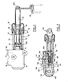
Si l'on considère la Figure 1, un correcteur de freinage 10 comprend un boîtier 12 pourvu d'un orifice d'entrée 14 et d'un orifice de sortie 16.Considering FIG. 1, a
L'orifice d'entrée 14 est relié à une source de fluide sous pression qui consiste par exemple en un maître cylindre de freinage (non représenté) et l'orifice de sortie 16 est relié à un ou plusieurs moteurs de frein (également non représentés). Enfin, le boîtier 12 est fixé sur le chàssis du véhicule.The
La structure interne du boîtier 12 n'est pas représentée en détail à cette Figure mais l'on pourra se reporter à la Figure 2 et à la description qui s'y réfère pour comprendre cette structure interne.The internal structure of the
A ce stade de la description, il sera simplement dit qu'une valve de compensateur est montée dans le boîtier 12 et que cette valve est commandée par un piston de compensateur 18 dont une extrémité 18a se projette hors du boîtier 12.At this stage of the description, it will simply be said that a compensator valve is mounted in the
Sur le boîtier 12 est fixé un ensemble d'asservissement 20 destiné à appliquer au piston 18 une force variable en fonction de la charge du véhicule.On the
Comme représenté, l'ensemble d'asservissement 20 comprend un poussoir 22 abrité dans un logement tubulaire 24 fixé lui-même sur le boîtier 12, par exemple par vissage. Un ressort de précharge 26 prend appui sur un épaulement rentrant 28 du logement 24 et sur une bride externe 30 du poussoir 22 pour solliciter ce dernier et le piston 18 vers l'intérieur du boîtier 12. A son extrémité opposée au piston 18, le poussoir 22 comprend une tête élargie 32 reçue dans une cavité 34 d'un dispositif de renvoi 36, lui-même en appui .sur une portée plane constituée par un siège annulaire 38 défini à l'extrémité du logement tubulaire 24.As shown, the
Le dispositif de renvoi 36 comprend un prolongement axial 40 dont l'extrémité libre 40a reçoit en accrochage un ressort d'asservissement 42 qui s'étend sensiblement perpendiculairement au prolongement 40.The
A son autre extrémité, le ressort 42 est relié à une partie non suspendue du véhicule, de manière non représentée.At its other end, the
L'ensemble d'asservissement 20 exerce par conséquent sur le piston 18 une force de commande obtenue par composition d'une poussée de précharge d'amplitude fixe exercée sur le poussoir 22 par le ressort de précharge 26 et d'une traction d'asservissement d'amplitude variable en fonction inverse de la charge du véhicule exercée par le ressort 42 par l'intermédiaire du dispositif de renvoi 36.The
On notera que de cette manière, le dispositif de renvoi 36 est monté pivotant par rapport au boîtier par une articulation du type à rotule, de telle sorte qu'il n'existe aucune orientation préférentielle pour le ressort 42 dans un plan sensiblement perpendiculaire à l'axe du dispositif de renvoi, ce qui ne serait pas le cas si la transmission de l'effort du ressort 42 sur le poussoir 22 était assurée par un système classique à levier. Ceci permet un grand choix à la fois quant à l'implantation du boîtier 12 sur le chassis du véhicule et quant au point d'accrochage de l'autre extrémité du ressort 42 sur une partie non suspendue du véhicule. Dans le cas présent, le type d'articulation à rotule qui a été choisi peut être défini comme une articulation à rotule et à portée plane.It will be noted that in this way, the
Par ailleurs, le tarage à vide du ressort de précharge 26 peut être assuré de manière indépendante en agissant sur le vissage du logement tubulaire 24 sur le boîtier 12. De même, on conçoit que le montage du ressort d'asservissement 42 peut permettre un tarage indépendant de ce ressort.Furthermore, the vacuum calibration of the
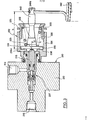
Dans le mode de réalisation illustré à la Figure 2, le correcteur 110 est directement associé à un cylindre de roue 150. Tous les éléments de ce correcteur qui sont identiques à ceux du premier mode de réalisation sont désignés par les mêmes numéros de référence augmentés de la valeur 100.In the embodiment illustrated in FIG. 2, the
A cette figure, on a illustré en détail la structure interne du boîtier 112. Dans ce dernier est prévu un alésage 152 dans lequel débouchent l'orifice d'entrée 114 et l'orifice de sortie 116. Entre l'orifice d'entrée 114 et l'extrémité ouverte de l'alésage 152 est monté un fourreau 154, ce dernier est maintenu en place par le logement tubulaire 124. Le piston 118 est étagé et comprend une partie de petit diamètre 118a coulissant dans le fourreau 154 et une partie de grand diamètre 118b coulissant dans l'alésage 152 entre l'orifice d'entrée 114 et l'orifice de sortie 116.In this figure, there is illustrated in detail the internal structure of the
Le piston 118 et l'alésage 152 définissent entre eux d'une part une chambre d'éntrée 156 adjacente à l'orifice d'entrée 114 et d'autre part une chambre de sortie 158 adjacente à l'orifice de sortie 116. Un passage 160, prévu dans le piston 118, relie les deux chambres 156 et 158 et une valve à bille 162 est montée dans le passage 160 pour commander l'écoulement de liquide de frein dans ce passage. Une butée 164, montée au fond de l'alésage 152, comporte un doigt 166 qui se projette en direction de la bille de la valve 162 pour provoquer l'ouverture de cette dernière lorsque le piston se déplace en rapprochement de cette butée.The
Dans ce mode de réalisation, le correcteur 110 est directement associé à un cylindre de roue150 de la manière suivante:
- le
boîtier 112 comprend unsecond alésage 168, sensiblement perpendiculaire à l'alésage 152, aux deux extrémités duquel coulissent deux pistons moteurs 170 et 172, le premier étant seul représenté à cette figure. Entre les deux pistons moteurs est définie une chambre de travail 174 qui communique directement avec l'orifice desortie 116. On conçoit que grâce à ce mode de réalisation on dispose ainsi d'un ensemble "correcteur+cylindre de roue" particulièrement compact.
- the
housing 112 comprises asecond bore 168, substantially perpendicular to thebore 152, at the two ends of which slide twoengine pistons 170 and 172, the first being the only one shown in this figure. Between the two engine pistons is defined a working chamber 174 which communicates directly with theoutlet orifice 116. It is understood that thanks to this embodiment there is thus a particularly compact "corrector + wheel cylinder" assembly.
On notera que dans ce cas, le boîtier du correcteur est fixé à une partie non suspendue du véhicule et que l'extrémité libre du ressort d'asservissement 142 est reliée au chassis du véhicule. Naturellement, ce type d'implantation peut également être choisi pour le premier mode de réalisation.It will be noted that in this case, the corrector box is fixed to an unsprung part of the vehicle and that the free end of the
Pour la description des appareils des Figures 3 et 4, les éléments identiques à ceux des correcteurs des Figures 1 et 2 porteront le même numéro de référence, augmenté respectivement des valeurs 200 et 300.For the description of the devices of Figures 3 and 4, the elements identical to those of the correctors of Figures 1 and 2 will bear the same reference number, increased by the values 200 and 300 respectively.
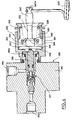
Ainsi, à la Figure 3, le correcteur 210 comprend un boitier 212 fixé sur le chassis du véhicule et pourvu d'un orifice d'entrée 214 et d'un orifice de sortie 216, l'orifice d'entrée étant relié au maître-cylindre (non représenté) du véhicule et l'orifice de sortie étant relié aux moteurs de freins arrière (également non représentés). Dans le boîtier 212 est montée une valve de correcteur 217 qui est commandée par un piston de correcteur 218 dont une extrémité 218a se projette hors du boîtier 212.Thus, in FIG. 3, the
Là valve de correcteur 217 étant identique à celle de la Figure 2, ne sera pas décrite en détail.The
Sur le boîtier 212 est fixé un ensemble d'asservissement 220 destiné à appliquer au piston 218 une force variable en fonction de la charge du véhicule.On the
Comme représenté, l'ensemble d'asservissement 220 comprend un poussoir 222 abrité dans un logement tubulaire 224 fixé lui-même sur le boîtier 212, par exemple par vissage. Un ressort de précharge 226 prend appui sur un épaulement rentrant 228 du logement 224.et sur une bride externe 230 du poussoir 222 pour solliciter ce dernier et lé piston 218 versl'intérieur du boîtier 212.As shown, the
Dans ce mode de réalisation, le poussoir 222 constitue lui-même un dispositif de renvoi, de la manière suivante: la bride 230 prend appui sur une portée plane constituée par un siègé annulaire 238 défini dans le logement tubulaire 224 et le poussoir 222 comprend un prolongement axial 240 dont l'extrémité libre 240a reçoit en accrochage un ressort d'asservissement 242 qui s'étend sensiblement perpendiculairement au poussoir 222. A son autre extrémité, le ressort 242 est relié à une partie non suspendue du véhicule, de manière non représentée.In this embodiment, the
L'ensemble d'asservissement 220 exerce par conséquent sur le piston 218 une force de commande obtenue par composition d'une poussée axiale de précharge d'amplitude fixe.exercéesur le poussoir 222 par le ressort de précharge 226 et d'une traction axiale d'asservissaient d'amplitude variable en fonction inverse de la charge du véhicule, cette traction axiale d'asservissement résultant, par basculement du poussoir 222 sur la portée 238, de la force exercée par le ressort 242 sur l'extrémité libre 240a du poussoir 222.The
On notera que le poussoir 222 est en contact avec le piston 218 par l'intermédiaire d'une saillie arrondie 229 de sorte que la force exercée par le poussoir 222 sur le piston 218 reste constamment parallèle à l'axe de ce dernier.It will be noted that the
Enfin, la face 231 par laquelle la bride 230 prend appui sur le siège annulaire 238 est profilée de telle manière que quelque soit l'angle de basculement du poussoir, le rapport des distances (h) et (d) reste constant, la distance (h) étant la distance séparant axialement le siège annulaire 238 du point d'accrochage du ressort d'asservissement 242 sur . l'extrémité 240a du poussoir, et la distance (d) étant la distance radiale séparant le point de contact entre le poussoir 229 et le piston 218 du point de contact entre le poussoir 231 et son siège annulaire 238.Finally, the
En annexe, on remarquera que l'épaulement rentrant 228 sur lequel prend appui le ressort dé précharge 226 est défini sur une bague 225 montée axialement réglable sur le logement tubulaire 224, par exemple par vissage. De la sorte, on peut aisément faire varier le tarage initial du ressort de précharge 226.In the appendix, it will be noted that the
Ce correcteur présente, par rapport aux modes de réalisation précédents, les avantages suivants:
- - réduction de l'encombrement axial du correcteur,
- - diminution du nombre de pièces,
- - simplification de l'assemblage, sans altérer les avantages déjà procurés par les correcteurs précédents.
- - reduction of the axial size of the corrector,
- - reduction in the number of parts,
- - simplification of assembly, without altering the advantages already provided by the previous correctors.
A la Figure 4, le correcteur 310 comporte la modification suivante: le ressort de précharge 326 prend appui sur le poussoir 322 par l'intermédiaire d'une coupelle 344, le poussoir 322 et la coupelle 344 comportant deux portées sphériques346 et 348 complémentaires.In FIG. 4, the
L'avantage d'une telle disposition est d'éviter la distorsion du ressort de précharge 326 lors du basculement du poussoir 322, en particulier si l'on considère que ce basculement peut s'effectuer dans n'importe quelle direction.The advantage of such an arrangement is to avoid distortion of the
Dans le cas du correcteur 210 de la Figure 3, la force de précharge exercée par le ressort 226 sur le poussoir 222 lors du basculement de ce dernier peut subir des variations en fonction de la direction de basculement en raison du fait que les spires de ce ressort subissent des déformations différentes selon cette direction de basculement.In the case of the
Au contraire, dans le correcteur de la Figure 4, le ressort de précharge 326 subit une compression sensiblement axiale quelle que soit la direction de basculement du poussoir 322, par le fait que la coupelle 344 reste parallèle à elle-même, par basculement sur la portée sphérique 348 du poussoir 322. On évite ainsi l'inconvénient précédemment cité.On the contrary, in the corrector of FIG. 4, the
Claims (11)
Applications Claiming Priority (4)
| Application Number | Priority Date | Filing Date | Title |
|---|---|---|---|
| FR8025291 | 1980-11-28 | ||
| FR8025291A FR2495079A1 (en) | 1980-11-28 | 1980-11-28 | Braking pressure control device - has tension spring applying force tending to reduce brake pressure |
| FR8111497A FR2507557B2 (en) | 1981-06-11 | 1981-06-11 | BRAKE PRESSURE CORRECTIVE CONTROLLER LOADED BY A VEHICLE |
| FR8111497 | 1981-06-11 |
Publications (2)
| Publication Number | Publication Date |
|---|---|
| EP0053528A1 true EP0053528A1 (en) | 1982-06-09 |
| EP0053528B1 EP0053528B1 (en) | 1984-08-29 |
Family
ID=26222096
Family Applications (1)
| Application Number | Title | Priority Date | Filing Date |
|---|---|---|---|
| EP81401706A Expired EP0053528B1 (en) | 1980-11-28 | 1981-10-27 | Brake pressure proportioning valve |
Country Status (5)
| Country | Link |
|---|---|
| US (1) | US4448457A (en) |
| EP (1) | EP0053528B1 (en) |
| AU (1) | AU542867B2 (en) |
| DE (1) | DE3165791D1 (en) |
| ES (1) | ES8300595A1 (en) |
Cited By (3)
| Publication number | Priority date | Publication date | Assignee | Title |
|---|---|---|---|---|
| FR2591168A1 (en) * | 1985-12-11 | 1987-06-12 | Bendix France | BRAKE CORRECTION WITH VARIABLE RATIO BASED ON THE LOAD OF A VEHICLE |
| EP0261011A1 (en) * | 1986-09-18 | 1988-03-23 | BENDIX France Société Anonyme dite: | Load-dependent brake pressure control valve |
| KR19990041132A (en) * | 1997-11-21 | 1999-06-15 | 정몽규 | Load sensing proportioning valve for automotive brake system |
Families Citing this family (4)
| Publication number | Priority date | Publication date | Assignee | Title |
|---|---|---|---|---|
| FR2562017B1 (en) * | 1984-03-28 | 1986-07-18 | Dba | SAFETY DEVICE ON BRAKE CORRECTOR |
| FR2564401B1 (en) * | 1984-05-17 | 1989-07-28 | Dba | CONTROL DEVICE FOR BRAKE CORRECTOR |
| GB8518706D0 (en) * | 1985-07-24 | 1985-08-29 | Lucas Ind Plc | Brake pressure reducing valve |
| JPH0322055Y2 (en) * | 1986-10-27 | 1991-05-14 |
Citations (5)
| Publication number | Priority date | Publication date | Assignee | Title |
|---|---|---|---|---|
| FR1282714A (en) * | 1960-12-16 | 1962-01-27 | Renault | Brake corrector for vehicles |
| GB1239289A (en) * | 1968-09-17 | 1971-07-14 | ||
| FR2112043A1 (en) * | 1970-08-05 | 1972-06-16 | Peugeot & Renault | |
| GB1385180A (en) * | 1970-11-04 | 1975-02-26 | Woodhead Ltd John | Vehicles having hydraulically operated braking systems |
| FR2322034A2 (en) * | 1975-08-30 | 1977-03-25 | Bosch Gmbh Robert | Load sensitive brake control valve - with manual set screw for min. pressure setting up to set loading |
Family Cites Families (4)
| Publication number | Priority date | Publication date | Assignee | Title |
|---|---|---|---|---|
| DE1655299C3 (en) * | 1966-10-18 | 1974-07-18 | Alfred Teves Gmbh, 6000 Frankfurt | Load-dependent brake pressure regulator for a vehicle brake system that can be actuated by pressure means, in particular a motor vehicle brake system |
| JPS4930975B1 (en) * | 1968-05-04 | 1974-08-17 | ||
| FR2049225A5 (en) * | 1969-06-04 | 1971-03-26 | Renault | |
| US4101176A (en) * | 1975-04-01 | 1978-07-18 | Societe Anonyme Dba | Braking correction device |
-
1981
- 1981-10-27 DE DE8181401706T patent/DE3165791D1/en not_active Expired
- 1981-10-27 EP EP81401706A patent/EP0053528B1/en not_active Expired
- 1981-11-02 US US06/317,088 patent/US4448457A/en not_active Expired - Fee Related
- 1981-11-10 AU AU77344/81A patent/AU542867B2/en not_active Ceased
- 1981-11-27 ES ES507531A patent/ES8300595A1/en not_active Expired
Patent Citations (5)
| Publication number | Priority date | Publication date | Assignee | Title |
|---|---|---|---|---|
| FR1282714A (en) * | 1960-12-16 | 1962-01-27 | Renault | Brake corrector for vehicles |
| GB1239289A (en) * | 1968-09-17 | 1971-07-14 | ||
| FR2112043A1 (en) * | 1970-08-05 | 1972-06-16 | Peugeot & Renault | |
| GB1385180A (en) * | 1970-11-04 | 1975-02-26 | Woodhead Ltd John | Vehicles having hydraulically operated braking systems |
| FR2322034A2 (en) * | 1975-08-30 | 1977-03-25 | Bosch Gmbh Robert | Load sensitive brake control valve - with manual set screw for min. pressure setting up to set loading |
Cited By (6)
| Publication number | Priority date | Publication date | Assignee | Title |
|---|---|---|---|---|
| FR2591168A1 (en) * | 1985-12-11 | 1987-06-12 | Bendix France | BRAKE CORRECTION WITH VARIABLE RATIO BASED ON THE LOAD OF A VEHICLE |
| EP0226509A1 (en) * | 1985-12-11 | 1987-06-24 | BENDIX France | Load-sensitive proportional valve |
| US4744608A (en) * | 1985-12-11 | 1988-05-17 | Bendix France | Braking corrector |
| EP0261011A1 (en) * | 1986-09-18 | 1988-03-23 | BENDIX France Société Anonyme dite: | Load-dependent brake pressure control valve |
| FR2604136A1 (en) * | 1986-09-18 | 1988-03-25 | Bendix France | BRAKE CORRECTOR SERVO-LOADED BY A VEHICLE |
| KR19990041132A (en) * | 1997-11-21 | 1999-06-15 | 정몽규 | Load sensing proportioning valve for automotive brake system |
Also Published As
| Publication number | Publication date |
|---|---|
| AU542867B2 (en) | 1985-03-21 |
| EP0053528B1 (en) | 1984-08-29 |
| AU7734481A (en) | 1982-06-03 |
| ES507531A0 (en) | 1982-11-01 |
| US4448457A (en) | 1984-05-15 |
| ES8300595A1 (en) | 1982-11-01 |
| DE3165791D1 (en) | 1984-10-04 |
Similar Documents
| Publication | Publication Date | Title |
|---|---|---|
| EP0283328A1 (en) | Load-dependent brake pressure proportioning valve | |
| EP0156666A1 (en) | Brake pressure regulator | |
| EP0501843B1 (en) | Servo brake booster with an adjustable threshold value and procedure for regulating same | |
| BE1005849A5 (en) | Adjustable reservoir capacity for liquid product. | |
| EP0053528B1 (en) | Brake pressure proportioning valve | |
| EP0340059B1 (en) | Servo brake booster with an adjustable threshold value | |
| EP0402183B1 (en) | Procedure for regulating the value of a jump at a servo-unit for brakes | |
| EP0335764B1 (en) | Load sensitive brake force corrector with vehicle height sensor | |
| FR2495079A1 (en) | Braking pressure control device - has tension spring applying force tending to reduce brake pressure | |
| EP0192547B1 (en) | Actuating device for a double master brake cylinder | |
| EP0462849A1 (en) | Vacuum brake booster | |
| WO1994001311A1 (en) | Tandem master cylinder having reduced pressure imbalance | |
| EP0262999B1 (en) | Load-sensitive brake valve for a vehicle | |
| EP0142395B1 (en) | Automatically adjustable disc brake actuating device | |
| FR2513954A1 (en) | BRAKE CORRECTOR ACCORDING TO DECELERATION | |
| EP1057704B1 (en) | Improved brake servo | |
| FR2608540A1 (en) | PRESSURE DISTRIBUTOR, ESPECIALLY FOR A MOTOR VEHICLE BRAKING SYSTEM, WITH PRESSURE FLUID CONTROL | |
| EP0430746A1 (en) | Attachment device, especially for attaching an axle of a rear wheel suspension of a motor vehicle to the body | |
| FR2507557A2 (en) | Braking pressure control device - has tension spring applying force tending to reduce brake pressure | |
| FR2515580A1 (en) | Shock absorber for car - consists of fluid cylinder with piston rod and wheel axle mounting | |
| EP0380895B1 (en) | Vehicle load dependent brake force regulator | |
| FR2755929A1 (en) | ASSISTED BRAKING SYSTEM WITH IMPROVED HYDRAULIC REACTION | |
| EP0449703B1 (en) | Procedure for regulating the threshold value of a brake servo-unit | |
| EP0933273B1 (en) | Vehicle load dependent dual circuit braking corrector | |
| EP0082044A1 (en) | Vehicle brake force regulator |
Legal Events
| Date | Code | Title | Description |
|---|---|---|---|
| PUAI | Public reference made under article 153(3) epc to a published international application that has entered the european phase |
Free format text: ORIGINAL CODE: 0009012 |
|
| 17P | Request for examination filed |
Effective date: 19811030 |
|
| AK | Designated contracting states |
Designated state(s): DE FR GB IT SE |
|
| ITF | It: translation for a ep patent filed |
Owner name: ING. ZINI MARANESI & C. S.R.L. |
|
| GRAA | (expected) grant |
Free format text: ORIGINAL CODE: 0009210 |
|
| AK | Designated contracting states |
Designated state(s): DE FR GB IT SE |
|
| REF | Corresponds to: |
Ref document number: 3165791 Country of ref document: DE Date of ref document: 19841004 |
|
| PLBE | No opposition filed within time limit |
Free format text: ORIGINAL CODE: 0009261 |
|
| STAA | Information on the status of an ep patent application or granted ep patent |
Free format text: STATUS: NO OPPOSITION FILED WITHIN TIME LIMIT |
|
| 26N | No opposition filed | ||
| ITTA | It: last paid annual fee | ||
| PGFP | Annual fee paid to national office [announced via postgrant information from national office to epo] |
Ref country code: SE Payment date: 19941017 Year of fee payment: 14 |
|
| PGFP | Annual fee paid to national office [announced via postgrant information from national office to epo] |
Ref country code: GB Payment date: 19941018 Year of fee payment: 14 |
|
| PGFP | Annual fee paid to national office [announced via postgrant information from national office to epo] |
Ref country code: DE Payment date: 19941021 Year of fee payment: 14 |
|
| EAL | Se: european patent in force in sweden |
Ref document number: 81401706.7 |
|
| PGFP | Annual fee paid to national office [announced via postgrant information from national office to epo] |
Ref country code: FR Payment date: 19951012 Year of fee payment: 15 |
|
| PG25 | Lapsed in a contracting state [announced via postgrant information from national office to epo] |
Ref country code: GB Effective date: 19951027 |
|
| PG25 | Lapsed in a contracting state [announced via postgrant information from national office to epo] |
Ref country code: SE Effective date: 19951028 |
|
| GBPC | Gb: european patent ceased through non-payment of renewal fee |
Effective date: 19951027 |
|
| EUG | Se: european patent has lapsed |
Ref document number: 81401706.7 |
|
| PG25 | Lapsed in a contracting state [announced via postgrant information from national office to epo] |
Ref country code: DE Effective date: 19960801 |
|
| PG25 | Lapsed in a contracting state [announced via postgrant information from national office to epo] |
Ref country code: FR Effective date: 19970630 |
|
| REG | Reference to a national code |
Ref country code: FR Ref legal event code: ST |