EP1055978A2 - Roller-shaped heater and fusing unit using a roller-shaped heater - Google Patents
Roller-shaped heater and fusing unit using a roller-shaped heater Download PDFInfo
- Publication number
- EP1055978A2 EP1055978A2 EP00110519A EP00110519A EP1055978A2 EP 1055978 A2 EP1055978 A2 EP 1055978A2 EP 00110519 A EP00110519 A EP 00110519A EP 00110519 A EP00110519 A EP 00110519A EP 1055978 A2 EP1055978 A2 EP 1055978A2
- Authority
- EP
- European Patent Office
- Prior art keywords
- roller
- heat generator
- resistance heating
- heating elements
- shaped heater
- Prior art date
- Legal status (The legal status is an assumption and is not a legal conclusion. Google has not performed a legal analysis and makes no representation as to the accuracy of the status listed.)
- Granted
Links
- 238000010438 heat treatment Methods 0.000 claims abstract description 120
- 239000012774 insulation material Substances 0.000 claims abstract description 28
- 238000003825 pressing Methods 0.000 claims description 35
- 230000002093 peripheral effect Effects 0.000 abstract description 13
- 229910052751 metal Inorganic materials 0.000 description 25
- 239000002184 metal Substances 0.000 description 25
- 108091008695 photoreceptors Proteins 0.000 description 13
- 238000000034 method Methods 0.000 description 8
- 238000001514 detection method Methods 0.000 description 6
- 238000009413 insulation Methods 0.000 description 5
- 239000010410 layer Substances 0.000 description 5
- 230000004913 activation Effects 0.000 description 4
- 230000000994 depressogenic effect Effects 0.000 description 4
- 229910052736 halogen Inorganic materials 0.000 description 4
- 150000002367 halogens Chemical class 0.000 description 4
- 229910052782 aluminium Inorganic materials 0.000 description 3
- XAGFODPZIPBFFR-UHFFFAOYSA-N aluminium Chemical compound [Al] XAGFODPZIPBFFR-UHFFFAOYSA-N 0.000 description 3
- 230000003068 static effect Effects 0.000 description 3
- 239000004642 Polyimide Substances 0.000 description 2
- 230000009471 action Effects 0.000 description 2
- 239000000853 adhesive Substances 0.000 description 2
- 230000001070 adhesive effect Effects 0.000 description 2
- 238000004140 cleaning Methods 0.000 description 2
- 230000009849 deactivation Effects 0.000 description 2
- 238000010586 diagram Methods 0.000 description 2
- 239000003989 dielectric material Substances 0.000 description 2
- 230000005684 electric field Effects 0.000 description 2
- 239000011810 insulating material Substances 0.000 description 2
- 238000004519 manufacturing process Methods 0.000 description 2
- 239000000463 material Substances 0.000 description 2
- 229920001721 polyimide Polymers 0.000 description 2
- 238000000926 separation method Methods 0.000 description 2
- 239000010935 stainless steel Substances 0.000 description 2
- 229910001220 stainless steel Inorganic materials 0.000 description 2
- 229910000975 Carbon steel Inorganic materials 0.000 description 1
- RYGMFSIKBFXOCR-UHFFFAOYSA-N Copper Chemical compound [Cu] RYGMFSIKBFXOCR-UHFFFAOYSA-N 0.000 description 1
- 230000003213 activating effect Effects 0.000 description 1
- 238000013019 agitation Methods 0.000 description 1
- 239000010962 carbon steel Substances 0.000 description 1
- 239000000919 ceramic Substances 0.000 description 1
- 239000011247 coating layer Substances 0.000 description 1
- 238000007796 conventional method Methods 0.000 description 1
- 229910052802 copper Inorganic materials 0.000 description 1
- 239000010949 copper Substances 0.000 description 1
- 229920001971 elastomer Polymers 0.000 description 1
- 238000005530 etching Methods 0.000 description 1
- 239000011521 glass Substances 0.000 description 1
- 239000004519 grease Substances 0.000 description 1
- WABPQHHGFIMREM-UHFFFAOYSA-N lead(0) Chemical compound [Pb] WABPQHHGFIMREM-UHFFFAOYSA-N 0.000 description 1
- 230000003287 optical effect Effects 0.000 description 1
- 229920001296 polysiloxane Polymers 0.000 description 1
- 239000004810 polytetrafluoroethylene Substances 0.000 description 1
- 229920001343 polytetrafluoroethylene Polymers 0.000 description 1
- 230000009467 reduction Effects 0.000 description 1
- 239000011347 resin Substances 0.000 description 1
- 229920005989 resin Polymers 0.000 description 1
- 230000004044 response Effects 0.000 description 1
- 229920002379 silicone rubber Polymers 0.000 description 1
- 239000004945 silicone rubber Substances 0.000 description 1
- BFKJFAAPBSQJPD-UHFFFAOYSA-N tetrafluoroethene Chemical group FC(F)=C(F)F BFKJFAAPBSQJPD-UHFFFAOYSA-N 0.000 description 1
- 238000011144 upstream manufacturing Methods 0.000 description 1
- 230000000007 visual effect Effects 0.000 description 1
Images


Classifications
-
- G—PHYSICS
- G03—PHOTOGRAPHY; CINEMATOGRAPHY; ANALOGOUS TECHNIQUES USING WAVES OTHER THAN OPTICAL WAVES; ELECTROGRAPHY; HOLOGRAPHY
- G03G—ELECTROGRAPHY; ELECTROPHOTOGRAPHY; MAGNETOGRAPHY
- G03G15/00—Apparatus for electrographic processes using a charge pattern
- G03G15/20—Apparatus for electrographic processes using a charge pattern for fixing, e.g. by using heat
- G03G15/2003—Apparatus for electrographic processes using a charge pattern for fixing, e.g. by using heat using heat
- G03G15/2014—Apparatus for electrographic processes using a charge pattern for fixing, e.g. by using heat using heat using contact heat
- G03G15/2053—Structural details of heat elements, e.g. structure of roller or belt, eddy current, induction heating
-
- H—ELECTRICITY
- H05—ELECTRIC TECHNIQUES NOT OTHERWISE PROVIDED FOR
- H05B—ELECTRIC HEATING; ELECTRIC LIGHT SOURCES NOT OTHERWISE PROVIDED FOR; CIRCUIT ARRANGEMENTS FOR ELECTRIC LIGHT SOURCES, IN GENERAL
- H05B3/00—Ohmic-resistance heating
- H05B3/0095—Heating devices in the form of rollers
Definitions
- a heat roller of this type is disclosed in Japanese Patent Application Laid-Open Hei 8 No.220915.
- a resistance heating element having a predetermined pattern is formed on an insulation sheet. This is referred to as a heat generator (heat generating sheet).
- the heat generator (heat generating sheet) is inserted into the heat roller interior with the resistance heating element oriented toward the central axis of the heat roller.
- the resistance heating element has a pair of electric power supply strips disposed at both ends of the roller body and extending in the peripheral direction of the roller body and the power supply portions electrically connected to the resistance heating element is bonded, thus constituting the heat generator (heat generating sheet).
- a pair of electrodes are placed in frictional contact with these electric power supply portions so as to supply electric power to the resistance heating element via the power supply portions.
- the resistance heating element is supplied with power to heat itself and hence heat the entire roller.
- the present invention has been devised in order to solve the above problem and it is therefore an object of the present invention to provide a roller-shaped heater of which the heat generator can be readily set in close contact with the roller interior even the roller is small in diameter as well as providing a fusing unit using such a roller-shaped heater.
- a roller-shaped heater includes:
- a roller-shaped heater includes:
- the roller-shaped heater having the above first feature is characterized in that power receiving portions that receive electric power for the resistance heating elements formed in the heat generator are formed at one end of the heat generator.
- the roller-shaped heater having the above second feature is characterized in that power receiving portions that receive electric power for the resistance heating elements formed in the heat generator are formed at one end of the heat generator.
- a fusing unit includes: invention, a fusing unit includes:
- the fusing unit having the above fifth feature is characterized in that the roller-shaped heater has a power receiving portion at one end of the heat generator through which electric current is supplied to the resistance heating elements formed in the heat generator and the pressing member is disposed abutting against the roller-shaped heater, so that fusing is performed by conveying a recording medium having an unfused toner image supported thereon through the nip between the roller-shaped heater and the pressing member.
- the fusing unit having the above sixth feature is characterized in that the roller-shaped heater has a power receiving portion at one end of the heat generator through which electric current is supplied to the resistance heating elements formed in the heat generator and the pressing member is disposed abutting against the roller-shaped heater, so that fusing is performed by conveying a recording medium having an unfused toner image supported thereon through the nip between the roller-shaped heater and the pressing member.
- the fusing unit having the above fifth feature is characterized in that electric power is selectively supplied to one of the resistance heating elements in the heat generator which corresponds to the nip area formed between the roller-shaped heater and the pressing member.
- the fusing unit having the above sixth feature is characterized in that electric power is selectively supplied to one of the resistance heating elements in the heat generator which corresponds to the nip area formed between the roller-shaped heater and the pressing member.
- the fusing unit having the above seventh feature is characterized in that electric power is selectively supplied to one of the resistance heating elements in the heat generator which corresponds to the nip area formed between the roller-shaped heater and the pressing member.
- the fusing unit having the above eighth feature is characterized in that electric power is selectively supplied to one of the resistance heating elements in the heat generator which corresponds to the nip area formed between the roller-shaped heater and the pressing member.
- the fusing unit having the above fifth feature is characterized in that electric power can be supplied to all the resistance heating elements in the heat generator so that the entire roller-shaped heater is heated and also electric power can be selectively supplied to one of the resistance heating elements in the heat generator which corresponds to the nip area formed between the roller-shaped heater and the pressing member.
- the fusing unit having the above sixth feature is characterized in that electric power can be supplied to all the resistance heating elements in the heat generator so that the entire roller-shaped heater is heated and also electric power can be selectively supplied to one of the resistance heating elements in the heat generator which corresponds to the nip area formed between the roller-shaped heater and the pressing member.
- the fusing unit having the above seventh feature is characterized in that electric power can be supplied to all the resistance heating elements in the heat generator so that the entire roller-shaped heater is heated and also electric power can be selectively supplied to one of the resistance heating elements in the heat generator which corresponds to the nip area formed between the roller-shaped heater and the pressing member.
- the fusing unit having the above tenth feature further comprises: a power supply portion for supplying electric power to the heat generator; a power receiving portion which receives electric power from the power supply portion to supply the resistance heating elements formed in the heat generator, wherein the power supply portion and the power receiving portion are mated to each other in an interfitting manner.
- the fusing unit having the above twelfth feature further comprises: a power supply portion for supplying electric power to the heat generator; a power receiving portion which receives electric power from the power supply portion to supply the resistance heating elements formed in the heat generator, wherein the power supply portion and the power receiving portion are mated to each other in an interfitting manner.
- the fusing unit having the above fifteenth feature further comprises: a power supply portion for supplying electric power to the heat generator; a power receiving portion which receives electric power from the power supply portion to supply the resistance heating elements formed in the heat generator, wherein the power supply portion and the power receiving portion are mated to each other in an interfitting manner.
- the fusing unit having the above sixteenth feature further comprises: a power supply portion for supplying electric power to the heat generator; a power receiving portion which receives electric power from the power supply portion to supply the resistance heating elements formed in the heat generator, wherein the power supply portion and the power receiving portion are mated to each other in an interfitting manner.
- the present invention by providing a multiple number of resistance heating elements extending in parallel to each other on a single sheet of heat generator, it is possible to provide fusing unit using a roller-shaped heater which is capable of supplying the necessary portion with electric power to heat the selected portion locally.
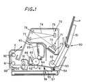
- paper P set in paper feed tray 51 is fed, sheet by sheet, by the functions of paper feed roller 52, paper separating friction plate 53 and pressing spring 54, into the printer interior. Paper P thus fed turns over paper detection actuator 55, whereby paper detection optical sensor 56 outputs an electric signal to instruct the start of image printing.
- Control circuit 57 activated by the operation of paper detecting actuator 55 sends an image signal to a laser diode light emitting unit 71 of laser scanning portion 70 so as to control activation and deactivation of the laser diode.
- the aforementioned laser scanning portion 70 includes the laser diode light emitting unit 71, a scanning mirror 72, a scanning mirror motor 73, reflection mirrors 75, 76 and 77.
- Scanning mirror 72 is rotated at a constant, high speed by scanning mirror motor 73.
- a laser beam 74 is deflected in the direction perpendicular to the document surface.
- Laser beam 74 emitted from laser diode light emitting unit 71 passes through reflection mirror 76, 75, 77 to illuminate an aftermentioned photoreceptor 61.
- laser beam 74 selectively illuminates the surface of photoreceptor 61, based on the information of activation and deactivation from the aforementioned control circuit 57.
- Image forming unit 60 includes a photoreceptor 61, a transfer roller 62, a charging member 63, a developing roller 64, a developing unit 65 and a cleaning unit 66.
- paper P is conveyed to fusing unit 80, where the paper with the toner is pressed at an appropriate temperature between a pressure roller 20 and a heat roller 10 which is kept a predetermined temperature.
- the toner fuses and is fused to paper P forming a stable image.
- Paper P then is conveyed and discharged to the outside by means of paper conveyance rollers 91 and 92.
- Pressure roller 20 has an outside diameter ⁇ of 25 mm, for example, and is composed of a metal core 21 of stainless steel ( ⁇ 22 mm) and a separation layer 22 made up of LTV (low temperature vulcanizing) silicone rubber layer (of 1.5 mm thick) formed on the metal core.
- a metal core 21 of stainless steel ⁇ 22 mm
- a separation layer 22 made up of LTV (low temperature vulcanizing) silicone rubber layer (of 1.5 mm thick) formed on the metal core.
- a temperature detecting means 16 (e.g., thermistor) for detecting the surface temperature of heat roller 10 is arranged upstream with respect to the rotational direction of heat roller 10, in the vicinity of the entrance of nip portion Wn.
- the detection signal from temperature detecting means 16 is sent to an unillustrated power supply control circuit, whereby the power supply to heat roller 10 is controlled based on the detection signal.
- any insulating material having heat resistance can be used other than polyimide.
- the resistance heating element any material such as copper etc. may be used as long as it can be used as resistance heating element.
- the thus formed heat generator 15 is inserted into the interior of metal core 11 of the roller in such a manner that, for example, resistance heating elements 14 are oriented toward the central axis and heat generator 15 comes in close contact with metal core 11, thus forming a roller-shaped heater.
- heat resistance insulation material 13 functions to provide insulation between metal core 11 and resistance heating element 14.
- heat generator 15 is provided on the inner side of metal core 11 but it can be provided on the inner side and/or outer peripheral surface of metal core 11.
- a heat-resisting adhesive e.g., silicone grease
- a heat generator can be fused with an adhesive, the heat generator cannot be replaced when it is damaged, so that the heat generator may be set into close contact with a adhesive-free means, such as a fastener member (for example, an insulating material such as rubber or the like may be inserted into the metal core interior so as to press the heat generating sheet outwardly, as disclosed in Japanese Patent Application Laid-Open Hei 9 No. 138605).
- a fastener member for example, an insulating material such as rubber or the like may be inserted into the metal core interior so as to press the heat generating sheet outwardly, as disclosed in Japanese Patent Application Laid-Open Hei 9 No. 138605).
- the arrangement of multiple heat generators over the entire inner peripheral surface of the roller as above provides easiness as compared to the conventional method of the arrangement in which a single heat generator needs to be arranged over the entire peripheral surface of the roller.
- a single sheet of heat generator 15 having a multiple number of resistance heating elements 14 may be formed as shown in Fig.4A.
- a multiple number of resistance heating elements 14 are arranged in having a predetermined pattern in parallel to each other with terminals 17 and 18 disposed at both ends thereof as shown in Fig.3A.
- the heat generator is arranged inside the metal core in the same manner as above so that both ends of resistance heating elements 14 are aligned with the axial direction of the roller (the roller-shaped metal core) and the faces of resistance heating elements 14 are oriented toward the roller's center (Fig.4B).
- power supply portion 32A As shown in Fig.6C, power supply portion 32A is set off the central axis of heat roller 10 downwards in the figure and is formed slightly greater in size than electrode 32 provided for power receiving portion 19. This manipulation can relax the positioning precision for contact between power supply portion 32A and electrode 32 of power receiving portion 19. Thus, by forming power supply portion 32A and power receiving portion 19 in almost the same shape and size, it is possible to supply electric power to the heat generator 15 which is positioned near the nip portion Wn of heat roller 10.
- the whole heat roller 10 needs to be heated.
- electric power is supplied via both first and second power supply portion 33 and 34 so as to heat all portions of the heat generator 15 arranged inside heat roller 10.
- voltage is applied only to first power supply portion 33 so that portion of the heat generator 15 residing around the nip portion Wn alone can be heated for fusing. In this way, it is possible to efficiently save electric power during fusing by supplying electric power only to portion of the heat generator 15 corresponding to the nip portion Wn.
- Fig.7A shows the method of supplying electric power when terminals 17 and 18 of resistance heating elements 14 of heat generator 15 are arranged on one side of heat-resisting insulation member 13.
- an intermediary member 30 Provided at one end inside metal core 11 is an intermediary member 30 made up of an electric insulator.
- This intermediary member 30 has a power receiving portion 19.
- this power receiving portion 19 has a multiple number of first electrodes 37 and a second electrode 38, which come into contact with respective first power supply portion 35 and second power supply portion 36 provided for a supporter 31.
- resistance heating elements 14 of heat generator 15 fused inside the metal core are connected at one end by lead wires 33A to associated electrodes (first electrodes 37) which are formed on a concentric circle in power receiving portion 19. The other ends are connected by lead wires to second electrode 38 corresponding to the central axis of the power receiving portion.
- one electrode portion (first electrodes 37) is arranged concentrically with respect to the central axis of heat roller 10 while the other electrode portion (second electrode 38) is arranged at a position corresponding to the central axis of the heat roller.
- first power supply portion 35 disposed off the central axis of heat roller 10 downwards in the drawing and the other (second power supply portion 36) disposed at a position corresponding to the central axis of power receiving portion 19.
- Each power supply portion is formed slightly greater in size than the associated electrode formed in power receiving portion 19. Since first electrodes 37 are provided corresponding to the first power supply portion, portion of the heat generator 15 residing around nip Wn of heat roller 10 can be activated as stated above so that it is possible to heat nip Wn and the nearby area to the predetermined temperature.
- Fig.7D shows another power supplying method.
- second power supply portion 36 located at the central axis of heat roller 10 is formed projected while second power receiving portion 39 that moves in sliding contact with the projection is formed depressed in the intermediary member.
- First power supply portion 35 disposed off the central axis of heat roller 10 downward in the drawing is formed depressed while a first power receiving portion 40 that moves in sliding contact with the first power supply portion is formed projected on a circumference concentric to the central axis.
- the power supply portions are formed depressed and projected while the power receiving portions are formed projected and depressed, respectively so that these are mated with each other.
- This configuration separates first power receiving portion 40 having first electrodes 37 that are arranged on the circumference, from second power receiving portion 39 having a second electrode 38 and hence is effective in preventing short-circuit.
- heat generator 15 having resistance heating elements 14 with their terminals arranged on one end, electric power is continuously supplied from second power supply portion 36 positioned at the central axis while only the resistance heating element 14 that passes through the nip portion Wn comes into sliding contact with first power supply portion 35. Resultantly, only the resistance heating element 14 that resides around the nip portion is energized thus making it possible to realize local heating.
- a multiple number of heat generator portions are arranged in parallel to each other over the entire surface (e.g., over the inner peripheral surface) of a roller-shaped heater. Accordingly, this configuration provides easiness in manufacturing compared to the conventional configuration in which a single sheet of heat generator is arranged over the entire peripheral surface of a roller-shaped heater.
- the present invention is effective for a small-diametric roller-shaped heater. Further, if the heat generator is partially damaged, conventionally it has been impossible to partially replace the heat generating sheet inside the roller-shaped heater. However, because the present embodiment uses a multiple number of heat generator portions, this configuration permits the damaged heat generator portion alone to be replaced, becoming more economical. Since the resistance heating elements are arranged in parallel with each other, it is possible to energize the predetermined area alone for heating.
- a roller-shaped heater when a roller-shaped heater has a relatively large diameter, a single heat generator can be set relatively easily. This configuration makes the manufacturing process more simple compared to the case where a multiple number of heat generator portions are set. Further, the arrangement of the resistance heating elements in parallel to each other makes possible local power activation and local heating of the predetermined area.
- the terminals of the resistance heating elements of the heat generator are arranged on one side of the heat-resisting insulation sheet and hence the power supply and receiving portions for electric power supply can be arranged on only one end. Therefore, this arrangement is simple compared to the configuration where the power receiving portions and power supply portions are arranged at both ends.
- a multiple number of resistance heating elements on the heat-resisting insulation material are aligned in parallel with the axial direction of the heat roller. This configuration makes it possible to selectively heat the resistance heating element around the nip portion alone without energizing all the resistance heating elements disposed inside the heat roller. Thus, this configuration allows more effective use of electric power than the case where the entire roller is heated.
- the power supply portion and power receiving portion are coupled with each other by an interfitting arrangement.
- This configuration is effective in preventing short-circuit between the power supply portion around the nip Wn area and the power supply portion at the center of the axis.
Landscapes
- Physics & Mathematics (AREA)
- General Physics & Mathematics (AREA)
- Fixing For Electrophotography (AREA)
- Control Of Resistance Heating (AREA)
- Resistance Heating (AREA)
Abstract
Description
Claims (24)
- A roller-shaped heater comprising:a cylindrically formed roller member; anda heat generator composed of a heat-resisting insulation material and resistance heating elements formed on the heat-resisting insulation material, characterized in that the heat generator is composed of a multiple number of separated portions extending in the axial direction of the cylinder of the roller member and each portion has the resistance heating element.
- A roller-shaped heater comprising:a cylindrically formed roller member; anda heat generator composed of a heat-resisting insulation material and resistance heating elements formed on the heat-resisting insulation material, characterized in that the heat generator is formed with a multiple number of resistance heating elements and the multiple number of resistance heating elements are arranged in parallel with each other in the axial direction of the cylinder of the roller member.
- The roller-shaped heater according to Claim 1, wherein power receiving portions that receive electric power for the resistance heating elements formed in the heat generator are formed at one end of the heat generator.
- The roller-shaped heater according to Claim 2, wherein power receiving portions that receive electric power for the resistance heating elements formed in the heat generator are formed at one end of the heat generator.
- A fusing unit comprising:a roller-shaped heater comprising: a cylindrically formed roller member; and a heat generator composed of a heat-resisting insulation material and resistance heating elements formed on the heat-resisting insulation material wherein the heat generator is composed of a multiple number of separated portions extending in the axial direction of the cylinder of the roller member and each portion has the resistance heating element; anda pressing member disposed abutting against the roller-shaped heater,
characterized in that fusing is performed by conveying a recording medium having an unfused toner image supported thereon through the nip between the roller-shaped heater and the pressing member. - A fusing unit comprising:a roller-shaped heater comprising: a cylindrically formed roller member; and a heat generator composed of a heat-resisting insulation material and resistance heating elements formed on the heat-resisting insulation material wherein the heat generator is provided with a multiple number of resistance heating elements extending in parallel with each other in the axial direction of the cylinder of the roller member; anda pressing member disposed abutting against the roller-shaped heater,
characterized in that fusing is performed by conveying a recording medium having an unfused toner image supported thereon through the nip between the roller-shaped heater and the pressing member. - The fusing unit according to Claim 5, wherein the roller-shaped heater has a power receiving portion at one end of the heat generator through which electric current is supplied to the resistance heating elements formed in the heat generator and the pressing member is disposed abutting against the roller-shaped heater, so that fusing is performed by conveying a recording medium having an unfused toner image supported thereon through the nip between the roller-shaped heater and the pressing member.
- The fusing unit according to Claim 6, wherein the roller-shaped heater has a power receiving portion at one end of the heat generator through which electric current is supplied to the resistance heating elements formed in the heat generator and the pressing member is disposed abutting against the roller-shaped heater, so that fusing is performed by conveying a recording medium having an unfused toner image supported thereon through the nip between the roller-shaped heater and the pressing member.
- The fusing unit according to Claim 5, wherein electric power is selectively supplied to one of the resistance heating elements in the heat generator which corresponds to the nip area formed between the roller-shaped heater and the pressing member.
- The fusing unit according to Claim 6, wherein electric power is selectively supplied to one of the resistance heating elements in the heat generator which corresponds to the nip area formed between the roller-shaped heater and the pressing member.
- The fusing unit according to Claim 7, wherein electric power is selectively supplied to one of the resistance heating elements in the heat generator which corresponds to the nip area formed between the roller-shaped heater and the pressing member.
- The fusing unit according to Claim 8, wherein electric power is selectively supplied to one of the resistance heating elements in the heat generator which corresponds to the nip area formed between the roller-shaped heater and the pressing member.
- The fusing unit according to Claim 5, wherein electric power can be supplied to all the resistance heating elements in the heat generator so that the entire roller-shaped heater is heated and also electric power can be selectively supplied to one of the resistance heating elements in the heat generator which corresponds to the nip area formed between the roller-shaped heater and the pressing member.
- The fusing unit according to Claim 6, wherein electric power can be supplied to all the resistance heating elements in the heat generator so that the entire roller-shaped heater is heated and also electric power can be selectively supplied to one of the resistance heating elements in the heat generator which corresponds to the nip area formed between the roller-shaped heater and the pressing member.
- The fusing unit according to Claim 7, wherein electric power can be supplied to all the resistance heating elements in the heat generator so that the entire roller-shaped heater is heated and also electric power can be selectively supplied to one of the resistance heating elements in the heat generator which corresponds to the nip area formed between the roller-shaped heater and the pressing member.
- The fusing unit according to Claim 8, wherein electric power can be supplied to all the resistance heating elements in the heat generator so that the entire roller-shaped heater is heated and also electric power can be selectively supplied to one of the resistance heating elements in the heat generator which corresponds to the nip area formed between the roller-shaped heater and the pressing member.
- The fusing unit according to Claim 9, further comprising: a power supply portion for supplying electric power to the heat generator; a power receiving portion which receives electric power from the power supply portion to supply the resistance heating elements formed in the heat generator, wherein the power supply portion and the power receiving portion are mated to each other in an interfitting manner.
- The fusing unit according to Claim 10, further comprising: a power supply portion for supplying electric power to the heat generator; a power receiving portion which receives electric power from the power supply portion to supply the resistance heating elements formed in the heat generator, wherein the power supply portion and the power receiving portion are mated to each other in an interfitting manner.
- The fusing unit according to Claim 11, further comprising: a power supply portion for supplying electric power to the heat generator; a power receiving portion which receives electric power from the power supply portion to supply the resistance heating elements formed in the heat generator, wherein the power supply portion and the power receiving portion are mated to each other in an interfitting manner.
- The fusing unit according to Claim 12, further comprising: a power supply portion for supplying electric power to the heat generator; a power receiving portion which receives electric power from the power supply portion to supply the resistance heating elements formed in the heat generator, wherein the power supply portion and the power receiving portion are mated to each other in an interfitting manner.
- The fusing unit according to Claim 13, further comprising: a power supply portion for supplying electric power to the heat generator; a power receiving portion which receives electric power from the power supply portion to supply the resistance heating elements formed in the heat generator, wherein the power supply portion and the power receiving portion are mated to each other in an interfitting manner.
- The fusing unit according to Claim 14, further comprising: a power supply portion for supplying electric power to the heat generator; a power receiving portion which receives electric power from the power supply portion to supply the resistance heating elements formed in the heat generator, wherein the power supply portion and the power receiving portion are mated to each other in an interfitting manner.
- The fusing unit according to Claim 15, further comprising: a power supply portion for supplying electric power to the heat generator; a power receiving portion which receives electric power from the power supply portion to supply the resistance heating elements formed in the heat generator, wherein the power supply portion and the power receiving portion are mated to each other in an interfitting manner.
- The fusing unit according to Claim 16, further comprising: a power supply portion for supplying electric power to the heat generator; a power receiving portion which receives electric power from the power supply portion to supply the resistance heating elements formed in the heat generator, wherein the power supply portion and the power receiving portion are mated to each other in an interfitting manner.
Applications Claiming Priority (2)
| Application Number | Priority Date | Filing Date | Title |
|---|---|---|---|
| JP14613899 | 1999-05-26 | ||
| JP14613899A JP3670516B2 (en) | 1999-05-26 | 1999-05-26 | Roll heater and fixing device using roll heater |
Publications (3)
| Publication Number | Publication Date |
|---|---|
| EP1055978A2 true EP1055978A2 (en) | 2000-11-29 |
| EP1055978A3 EP1055978A3 (en) | 2002-04-10 |
| EP1055978B1 EP1055978B1 (en) | 2005-04-20 |
Family
ID=15401013
Family Applications (1)
| Application Number | Title | Priority Date | Filing Date |
|---|---|---|---|
| EP00110519A Expired - Lifetime EP1055978B1 (en) | 1999-05-26 | 2000-05-17 | Roller-shaped heater and fusing unit using a roller-shaped heater |
Country Status (4)
| Country | Link |
|---|---|
| US (1) | US6272308B1 (en) |
| EP (1) | EP1055978B1 (en) |
| JP (1) | JP3670516B2 (en) |
| DE (1) | DE60019488T2 (en) |
Cited By (3)
| Publication number | Priority date | Publication date | Assignee | Title |
|---|---|---|---|---|
| WO2009012369A3 (en) * | 2007-07-18 | 2009-07-30 | Watlow Electric Mfg | Thick film layered resistive device employing a dielectric tape |
| US8061402B2 (en) | 2008-04-07 | 2011-11-22 | Watlow Electric Manufacturing Company | Method and apparatus for positioning layers within a layered heater system |
| US8557082B2 (en) | 2007-07-18 | 2013-10-15 | Watlow Electric Manufacturing Company | Reduced cycle time manufacturing processes for thick film resistive devices |
Families Citing this family (12)
| Publication number | Priority date | Publication date | Assignee | Title |
|---|---|---|---|---|
| JP4351462B2 (en) * | 2003-04-01 | 2009-10-28 | 株式会社リコー | Fixing apparatus and image forming apparatus |
| JP5544801B2 (en) * | 2009-09-18 | 2014-07-09 | コニカミノルタ株式会社 | Fixing device |
| KR101705117B1 (en) * | 2009-10-20 | 2017-02-22 | 에스프린팅솔루션 주식회사 | Heating roller having resistive heating element and fusing device using the same |
| JP5282311B2 (en) * | 2010-05-27 | 2013-09-04 | コニカミノルタ株式会社 | Fixing apparatus and image forming apparatus |
| JP6140639B2 (en) * | 2014-04-17 | 2017-05-31 | 京セラドキュメントソリューションズ株式会社 | Fixing apparatus and image forming apparatus having the same |
| US20170363995A1 (en) * | 2016-06-20 | 2017-12-21 | Kabushiki Kaisha Toshiba | Heater and heating apparatus |
| JP2019215384A (en) * | 2016-10-17 | 2019-12-19 | 住友電気工業株式会社 | Self-heating type fixation roller and method for manufacturing self-heating type fixation roller |
| JP7558724B2 (en) | 2020-09-01 | 2024-10-01 | 東芝テック株式会社 | HEATER UNIT, FIXING DEVICE AND IMAGE FORMING APPARATUS |
| KR102667763B1 (en) * | 2021-08-31 | 2024-05-22 | 한국전자통신연구원 | Apparatus for gene amplification |
| JP2023141233A (en) * | 2022-03-23 | 2023-10-05 | 富士フイルムビジネスイノベーション株式会社 | Fixing device and image forming device |
| US12594774B2 (en) * | 2022-11-30 | 2026-04-07 | Ricoh Company, Ltd. | Heating device, image forming apparatus, and liquid discharge apparatus having heating roller with multiple fixed heating sources |
| JP2026017594A (en) * | 2024-07-24 | 2026-02-05 | 富士フイルムビジネスイノベーション株式会社 | Heating device and image forming device |
Family Cites Families (15)
| Publication number | Priority date | Publication date | Assignee | Title |
|---|---|---|---|---|
| JPS60131784A (en) * | 1983-12-19 | 1985-07-13 | キヤノン株式会社 | heat roller |
| US4724303A (en) * | 1986-08-06 | 1988-02-09 | Xerox Corporation | Instant-on fuser |
| JPH04296888A (en) * | 1991-03-27 | 1992-10-21 | Ricoh Co Ltd | Heating device |
| JP3113703B2 (en) * | 1991-08-01 | 2000-12-04 | 株式会社リコー | Fixing device |
| JPH08111279A (en) * | 1994-10-12 | 1996-04-30 | Brother Ind Ltd | Method of manufacturing heating roller for fixing |
| JPH08194401A (en) * | 1994-11-16 | 1996-07-30 | Brother Ind Ltd | Heating roller for fixing |
| JPH08179645A (en) * | 1994-12-22 | 1996-07-12 | Ricoh Co Ltd | Fixing device |
| JP3031526B2 (en) | 1995-02-13 | 2000-04-10 | ブラザー工業株式会社 | Heating roller for fixing |
| JPH08262912A (en) * | 1995-03-27 | 1996-10-11 | Ricoh Co Ltd | Heating roller and image forming apparatus using the same |
| JP3373973B2 (en) * | 1995-05-12 | 2003-02-04 | ブラザー工業株式会社 | Heating roller for fixing |
| JPH09197876A (en) * | 1996-01-17 | 1997-07-31 | Ricoh Co Ltd | Fixing device |
| JPH1048986A (en) * | 1996-08-08 | 1998-02-20 | Ricoh Co Ltd | Fixing roller and method of controlling temperature of fixing roller |
| JPH1115317A (en) * | 1997-06-25 | 1999-01-22 | Ricoh Co Ltd | Fixing device |
| US6137087A (en) * | 1997-12-26 | 2000-10-24 | Brother Kogyo Kabushiki Kaisha | Thermal roller for thermal fixing device |
| JPH11194634A (en) * | 1997-12-26 | 1999-07-21 | Brother Ind Ltd | Heating roller for fixing |
-
1999
- 1999-05-26 JP JP14613899A patent/JP3670516B2/en not_active Expired - Fee Related
-
2000
- 2000-04-26 US US09/558,642 patent/US6272308B1/en not_active Expired - Lifetime
- 2000-05-17 EP EP00110519A patent/EP1055978B1/en not_active Expired - Lifetime
- 2000-05-17 DE DE60019488T patent/DE60019488T2/en not_active Expired - Lifetime
Cited By (6)
| Publication number | Priority date | Publication date | Assignee | Title |
|---|---|---|---|---|
| WO2009012369A3 (en) * | 2007-07-18 | 2009-07-30 | Watlow Electric Mfg | Thick film layered resistive device employing a dielectric tape |
| US8089337B2 (en) | 2007-07-18 | 2012-01-03 | Watlow Electric Manufacturing Company | Thick film layered resistive device employing a dielectric tape |
| US8557082B2 (en) | 2007-07-18 | 2013-10-15 | Watlow Electric Manufacturing Company | Reduced cycle time manufacturing processes for thick film resistive devices |
| US9486988B2 (en) | 2007-07-18 | 2016-11-08 | Watlow Electric Manufacturing Company | Reduced cycle time manufacturing processes for thick film resistive devices |
| US8061402B2 (en) | 2008-04-07 | 2011-11-22 | Watlow Electric Manufacturing Company | Method and apparatus for positioning layers within a layered heater system |
| US8070899B2 (en) | 2008-04-07 | 2011-12-06 | Watlow Electric Manufacturing Company | Method and apparatus for positioning layers within a layered heater system |
Also Published As
| Publication number | Publication date |
|---|---|
| JP2000340336A (en) | 2000-12-08 |
| DE60019488T2 (en) | 2006-02-23 |
| EP1055978B1 (en) | 2005-04-20 |
| JP3670516B2 (en) | 2005-07-13 |
| US6272308B1 (en) | 2001-08-07 |
| DE60019488D1 (en) | 2005-05-25 |
| EP1055978A3 (en) | 2002-04-10 |
Similar Documents
| Publication | Publication Date | Title |
|---|---|---|
| US5262834A (en) | Image fixing apparatus | |
| US6272308B1 (en) | Roller-shaped heater and fusing unit using a roller-shaped heater | |
| JP2020148827A (en) | Fixing device and image forming device | |
| US7330688B2 (en) | Fixing device and image forming apparatus including the same | |
| JP2005142023A (en) | Heating apparatus, image forming apparatus including the same, and heating method of heating apparatus | |
| JP2002062752A (en) | Image forming apparatus | |
| JP3867190B2 (en) | Induction heating apparatus and image forming apparatus | |
| JP2728579B2 (en) | Electrophotographic equipment | |
| KR100708189B1 (en) | Fixerand image forming apparatus employing the same | |
| JPH1069208A (en) | Heating device and image forming device | |
| KR100708171B1 (en) | Fixing device and image forming apparatus having the same | |
| JPH0683224A (en) | Fixing device | |
| JP3252652B2 (en) | Heater assembly, heating device, and image forming device | |
| JP2001092282A (en) | Induction heating device | |
| JPH08305191A (en) | Heating device | |
| JP2003005573A (en) | Image heating device | |
| JP2001117405A (en) | Image forming apparatus having heat fixing device | |
| JPH02134667A (en) | Fixing heater and fixing device | |
| JP3824484B2 (en) | Fixing apparatus and image forming apparatus | |
| US7251446B2 (en) | Fuser and image forming apparatus | |
| JP2003076181A (en) | Heat fixing device and image forming apparatus using the same | |
| JP2006017935A (en) | Fixing device and image forming apparatus using the same | |
| JP2004047177A (en) | Heating device and image forming device | |
| JPH1184922A (en) | Heating device, fixing device, and image forming device | |
| JP2001028289A (en) | Roll heater and fixing device using the roll heater |
Legal Events
| Date | Code | Title | Description |
|---|---|---|---|
| PUAI | Public reference made under article 153(3) epc to a published international application that has entered the european phase |
Free format text: ORIGINAL CODE: 0009012 |
|
| AK | Designated contracting states |
Kind code of ref document: A2 Designated state(s): DE FR GB Kind code of ref document: A2 Designated state(s): AT BE CH CY DE DK ES FI FR GB GR IE IT LI LU MC NL PT SE |
|
| AX | Request for extension of the european patent |
Free format text: AL;LT;LV;MK;RO;SI |
|
| PUAL | Search report despatched |
Free format text: ORIGINAL CODE: 0009013 |
|
| AK | Designated contracting states |
Kind code of ref document: A3 Designated state(s): AT BE CH CY DE DK ES FI FR GB GR IE IT LI LU MC NL PT SE |
|
| AX | Request for extension of the european patent |
Free format text: AL;LT;LV;MK;RO;SI |
|
| 17P | Request for examination filed |
Effective date: 20020703 |
|
| AKX | Designation fees paid |
Free format text: DE FR GB |
|
| 17Q | First examination report despatched |
Effective date: 20031217 |
|
| GRAP | Despatch of communication of intention to grant a patent |
Free format text: ORIGINAL CODE: EPIDOSNIGR1 |
|
| GRAS | Grant fee paid |
Free format text: ORIGINAL CODE: EPIDOSNIGR3 |
|
| GRAA | (expected) grant |
Free format text: ORIGINAL CODE: 0009210 |
|
| AK | Designated contracting states |
Kind code of ref document: B1 Designated state(s): DE FR GB |
|
| REG | Reference to a national code |
Ref country code: GB Ref legal event code: FG4D |
|
| REG | Reference to a national code |
Ref country code: IE Ref legal event code: FG4D |
|
| REF | Corresponds to: |
Ref document number: 60019488 Country of ref document: DE Date of ref document: 20050525 Kind code of ref document: P |
|
| ET | Fr: translation filed | ||
| PLBE | No opposition filed within time limit |
Free format text: ORIGINAL CODE: 0009261 |
|
| STAA | Information on the status of an ep patent application or granted ep patent |
Free format text: STATUS: NO OPPOSITION FILED WITHIN TIME LIMIT |
|
| 26N | No opposition filed |
Effective date: 20060123 |
|
| REG | Reference to a national code |
Ref country code: FR Ref legal event code: PLFP Year of fee payment: 17 |
|
| REG | Reference to a national code |
Ref country code: FR Ref legal event code: PLFP Year of fee payment: 18 |
|
| REG | Reference to a national code |
Ref country code: FR Ref legal event code: PLFP Year of fee payment: 19 |
|
| PGFP | Annual fee paid to national office [announced via postgrant information from national office to epo] |
Ref country code: DE Payment date: 20180522 Year of fee payment: 19 |
|
| PGFP | Annual fee paid to national office [announced via postgrant information from national office to epo] |
Ref country code: FR Payment date: 20180522 Year of fee payment: 19 |
|
| PGFP | Annual fee paid to national office [announced via postgrant information from national office to epo] |
Ref country code: GB Payment date: 20180518 Year of fee payment: 19 |
|
| REG | Reference to a national code |
Ref country code: DE Ref legal event code: R119 Ref document number: 60019488 Country of ref document: DE |
|
| GBPC | Gb: european patent ceased through non-payment of renewal fee |
Effective date: 20190517 |
|
| PG25 | Lapsed in a contracting state [announced via postgrant information from national office to epo] |
Ref country code: DE Free format text: LAPSE BECAUSE OF NON-PAYMENT OF DUE FEES Effective date: 20191203 Ref country code: GB Free format text: LAPSE BECAUSE OF NON-PAYMENT OF DUE FEES Effective date: 20190517 |
|
| PG25 | Lapsed in a contracting state [announced via postgrant information from national office to epo] |
Ref country code: FR Free format text: LAPSE BECAUSE OF NON-PAYMENT OF DUE FEES Effective date: 20190531 |