EP1055927A1 - Method and device for the decomposition of a liquid solution to determine the carbon content - Google Patents
Method and device for the decomposition of a liquid solution to determine the carbon content Download PDFInfo
- Publication number
- EP1055927A1 EP1055927A1 EP00109435A EP00109435A EP1055927A1 EP 1055927 A1 EP1055927 A1 EP 1055927A1 EP 00109435 A EP00109435 A EP 00109435A EP 00109435 A EP00109435 A EP 00109435A EP 1055927 A1 EP1055927 A1 EP 1055927A1
- Authority
- EP
- European Patent Office
- Prior art keywords
- temperature
- furnace
- incinerator
- heating
- sample
- Prior art date
- Legal status (The legal status is an assumption and is not a legal conclusion. Google has not performed a legal analysis and makes no representation as to the accuracy of the status listed.)
- Granted
Links
- 238000000034 method Methods 0.000 title claims abstract description 26
- 229910052799 carbon Inorganic materials 0.000 title claims abstract description 11
- OKTJSMMVPCPJKN-UHFFFAOYSA-N Carbon Chemical compound [C] OKTJSMMVPCPJKN-UHFFFAOYSA-N 0.000 title claims abstract description 9
- 238000000354 decomposition reaction Methods 0.000 title 1
- 239000006193 liquid solution Substances 0.000 title 1
- 238000002485 combustion reaction Methods 0.000 claims abstract description 18
- 239000003054 catalyst Substances 0.000 claims abstract description 12
- 150000003839 salts Chemical class 0.000 claims abstract description 7
- 239000007864 aqueous solution Substances 0.000 claims abstract description 5
- XLYOFNOQVPJJNP-UHFFFAOYSA-N water Substances O XLYOFNOQVPJJNP-UHFFFAOYSA-N 0.000 claims abstract description 5
- 239000002351 wastewater Substances 0.000 claims abstract description 3
- 238000010438 heat treatment Methods 0.000 claims description 31
- 230000029087 digestion Effects 0.000 claims description 11
- 239000000919 ceramic Substances 0.000 claims description 9
- 238000009413 insulation Methods 0.000 claims description 8
- IJGRMHOSHXDMSA-UHFFFAOYSA-N Atomic nitrogen Chemical compound N#N IJGRMHOSHXDMSA-UHFFFAOYSA-N 0.000 claims description 6
- 239000000835 fiber Substances 0.000 claims description 5
- 238000006243 chemical reaction Methods 0.000 claims description 4
- 229910052757 nitrogen Inorganic materials 0.000 claims description 3
- 239000000463 material Substances 0.000 description 4
- 238000004804 winding Methods 0.000 description 4
- 230000003197 catalytic effect Effects 0.000 description 3
- 230000008030 elimination Effects 0.000 description 3
- 238000003379 elimination reaction Methods 0.000 description 3
- XEEYBQQBJWHFJM-UHFFFAOYSA-N Iron Chemical compound [Fe] XEEYBQQBJWHFJM-UHFFFAOYSA-N 0.000 description 2
- 239000000956 alloy Substances 0.000 description 2
- 229910045601 alloy Inorganic materials 0.000 description 2
- 239000012159 carrier gas Substances 0.000 description 2
- 239000000567 combustion gas Substances 0.000 description 2
- 238000012423 maintenance Methods 0.000 description 2
- 238000005259 measurement Methods 0.000 description 2
- QPLDLSVMHZLSFG-UHFFFAOYSA-N Copper oxide Chemical compound [Cu]=O QPLDLSVMHZLSFG-UHFFFAOYSA-N 0.000 description 1
- 239000005751 Copper oxide Substances 0.000 description 1
- VYPSYNLAJGMNEJ-UHFFFAOYSA-N Silicium dioxide Chemical compound O=[Si]=O VYPSYNLAJGMNEJ-UHFFFAOYSA-N 0.000 description 1
- FAPWRFPIFSIZLT-UHFFFAOYSA-M Sodium chloride Chemical compound [Na+].[Cl-] FAPWRFPIFSIZLT-UHFFFAOYSA-M 0.000 description 1
- XAGFODPZIPBFFR-UHFFFAOYSA-N aluminium Chemical compound [Al] XAGFODPZIPBFFR-UHFFFAOYSA-N 0.000 description 1
- 229910052782 aluminium Inorganic materials 0.000 description 1
- 238000004458 analytical method Methods 0.000 description 1
- 238000009835 boiling Methods 0.000 description 1
- 229910000431 copper oxide Inorganic materials 0.000 description 1
- 238000001514 detection method Methods 0.000 description 1
- 238000010586 diagram Methods 0.000 description 1
- 238000001035 drying Methods 0.000 description 1
- 238000005265 energy consumption Methods 0.000 description 1
- 238000001704 evaporation Methods 0.000 description 1
- 230000008020 evaporation Effects 0.000 description 1
- -1 for example Substances 0.000 description 1
- 239000010842 industrial wastewater Substances 0.000 description 1
- 229910052742 iron Inorganic materials 0.000 description 1
- 238000002955 isolation Methods 0.000 description 1
- 239000011159 matrix material Substances 0.000 description 1
- 230000008018 melting Effects 0.000 description 1
- 238000002844 melting Methods 0.000 description 1
- 238000012986 modification Methods 0.000 description 1
- 230000004048 modification Effects 0.000 description 1
- 230000003647 oxidation Effects 0.000 description 1
- 238000007254 oxidation reaction Methods 0.000 description 1
- 239000002245 particle Substances 0.000 description 1
- 230000000737 periodic effect Effects 0.000 description 1
- 239000010865 sewage Substances 0.000 description 1
- 239000011780 sodium chloride Substances 0.000 description 1
- 238000011144 upstream manufacturing Methods 0.000 description 1
Images

Classifications
-
- G—PHYSICS
- G01—MEASURING; TESTING
- G01N—INVESTIGATING OR ANALYSING MATERIALS BY DETERMINING THEIR CHEMICAL OR PHYSICAL PROPERTIES
- G01N31/00—Investigating or analysing non-biological materials by the use of the chemical methods specified in the subgroup; Apparatus specially adapted for such methods
- G01N31/12—Investigating or analysing non-biological materials by the use of the chemical methods specified in the subgroup; Apparatus specially adapted for such methods using combustion
-
- G—PHYSICS
- G01—MEASURING; TESTING
- G01N—INVESTIGATING OR ANALYSING MATERIALS BY DETERMINING THEIR CHEMICAL OR PHYSICAL PROPERTIES
- G01N33/00—Investigating or analysing materials by specific methods not covered by groups G01N1/00 - G01N31/00
- G01N33/18—Water
- G01N33/1826—Organic contamination in water
- G01N33/1846—Total carbon analysis
Definitions
- the invention relates to a method for digestion aqueous solution to determine the carbon content TOC (Total Organic Carbon) according to the generic term of the claim 1 and an apparatus for performing this method.
- TOC Total Organic Carbon
- DE 44 12 778 C1 describes a method for analyzing a particle-containing aqueous sample, especially for organic Carbon determination known in which the sample in injected a first combustion chamber, this through an associated heating device heated to about 1000 ° C and the sample is thereby vaporized and burned. To full combustion becomes the heater of the first Combustion chamber switched off and this cooled, and the Combustion gases are passed through a second, horizontally extending combustion chamber associated catalyst a heat treatment in the range between 800 ° C and Subject to 950 ° C.
- the combustion chamber is at this Arrangement formed by an L-shaped quartz glass tube. Whose Afterburning room is with an oxidation catalyst, for example, copper oxide filled.
- a method of the generic type is also from the EP 0 887 643 A1 is known.
- the sample initially from an initial temperature below the boiling temperature of the water to an evaporation temperature and in a second step to a much higher combustion temperature, preferably in the range between 800 and 1,000 ° C.
- a catalyst is described in not specified in this document; its need for the expert, however, results from the position of the chosen one Temperature range.
- the invention is therefore based on the object, a simplified process of the generic type to be handled and specify a device for performing this method.
- This task is regarding its procedural aspect by a method having the features of claim 1 and in terms of their device aspect by a device solved with the features of claim 6.
- the invention includes the essential idea of performing a purely thermal digestion without using a catalyst, as a departure from the thermal-catalytic type of digestion. It also includes the idea of substantially increasing the combustion temperature for this purpose, namely to values above 1000 ° C and preferably above 1200 ° C. Ultimately, it includes the thought of salt components in the samples at the end of the oven melt through "so that they can be easily removed there.
- the sample is immediately injected into a incinerator area kept at appropriate temperature to the combustion temperature, so preferred brought to more than 1200 ° C.
- a Two-step procedure applied in which the sample is first in a first digestion area kept at a maximum of 800 ° C and then in the preferred at more than 1200 ° C. held actual high-temperature digestion brought becomes.
- the first area of lower temperature serves thereby as a reduction zone.
- the incinerator has a high-temperature digestion zone, which is preferably kept above 1200 ° C, in one that enables simultaneous nitrogen determination advantageous embodiment a second, separate from the first Temperature zone in which a much lower Temperature, especially from below 800 ° C, is maintained.
- This can be either above or below the high temperature digestion zone be arranged; is taken for granted the specific arrangement of any existing loading arrangements to be coordinated.
- the oven preferred a vertical structure with also vertically arranged Recording space for receiving an elongated, essentially cylindrical ceramic reactor, in from the top of the furnace forth the sample to be examined and the carrier gas be initiated.
- the incinerator preferably has in the wall areas as well as below and above the heating zones and between them a ceramic fiber insulation.
- Operation is preferably carried out with low voltage, whereby for the two temperature zones, in which already due to the different temperatures different heating powers are used, also different supply voltages can be used.
- the preferred embodiment of the incinerator also has special features with regard to furnace control. Instead of the phase control that is usual for such loads, a so-called two-point soft control becomes one soft "load switching used in the zero crossing under control of the pulse / pause ratio.
- Fig. 1 shows a sample incinerator 1 in a Suitable implementation of the method according to the invention Execution in which an essentially elongated cylindrical Ceramic reaction vessel 1 (in the figure with a dashed line Line drawn in outline) can be used. This has a tubular one at the lower end (cold furnace end) Outlet with a diameter in the range between 6 and 10 mm, which is used to easily remove salt deposits can be cleaned below.
- the furnace 1 has a first, upper heating zone 3 in which this version reaches a maximum temperature of 800 ° C can be, and a second, lower heating zone 4 in which a maximum temperature of 1250 ° C is reached. Both heating zones are about hollow cylindrical around the corresponding Section of the reaction vessel 2 arranged heating wires 5, 6 made of a high temperature resistant special alloy, namely the Material Kanthal-Fibrothal®, heated.
- the top as well the lower heating zone - because of the different Maximum temperatures of different thicknesses - ceramic fiber insulation 7 or 8 on, and also the foot area, the area 10a, 10b between the heating zones and the area 11a, 11b below an aluminum cover 12 are ceramic fiber insulated.
- a sample feeder (not shown in the figure) and carrier gas supply device is in the area provided above the lid 12.
- the furnace structure shown in FIG. 1 and described above enables in an advantageous manner, the permanent realization specifically the high generated in the second, lower heating zone 4 Temperatures, the special insulation being both a justifiable energy expenditure contributes as well as hazards excludes the environment.
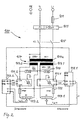
- the load circuit 100 of the incinerator 1 1 shown in a preferred embodiment.
- a primary winding 107a of a special transformer 107 with soft iron behavior characterized by an inductance of only 1.4 T
- the transformer 107 has two separate secondary windings 107.1 for the first heating zone (number 3 in Fig. 1) and 107.2 for the second heating zone (number 4 in Fig. 1) on.
- both heating zones each have an interference filter 109 of the switching device, namely a thyristor switch 111.1 for the first Heating zone or 111.2 upstream for the second heating zone.
- the thyristor switches 111.1, 111.2 are each one Controllers 113.1, 113.2 are activated and switch heating element arrangements 117.1 or 117.2 (corresponding to numbers 5 and 6 in Fig. 1).
- a super-fast fuse 115 is also provided.
- the controllers 113.1, 113.2 carry out a special two-point control behavior with switching only at zero crossing to avoid as much as possible Interference peaks in how they occur in "hard” switching operations.
- the transformer and the controllers together realize one for the method proposed here advantageous overall control behavior, characterized as a "two-point soft control" can be.
- the interpretation of the transformer is otherwise on the Properties of the low-voltage heating elements used here 117.1, 117.2 matched from a special alloy.
Landscapes
- Health & Medical Sciences (AREA)
- Life Sciences & Earth Sciences (AREA)
- Chemical & Material Sciences (AREA)
- Pathology (AREA)
- General Physics & Mathematics (AREA)
- Engineering & Computer Science (AREA)
- Physics & Mathematics (AREA)
- Analytical Chemistry (AREA)
- Biochemistry (AREA)
- General Health & Medical Sciences (AREA)
- Immunology (AREA)
- Food Science & Technology (AREA)
- Medicinal Chemistry (AREA)
- Combustion & Propulsion (AREA)
- Molecular Biology (AREA)
- Incineration Of Waste (AREA)
- Investigating Or Analyzing Non-Biological Materials By The Use Of Chemical Means (AREA)
Abstract
Description
Die Erfindung betrifft ein Verfahren zum Aufschluß einer
wässrigen Lösung zur Bestimmung des Kohlenstoffgehaltes
TOC(Total Organic Carbon) nach dem Oberbegriff des Anspruchs
1 sowie eine Vorrichtung zur Durchführung dieses Verfahrens.The invention relates to a method for digestion
aqueous solution to determine the carbon content
TOC (Total Organic Carbon) according to the generic term of the
Es ist bekannt, wässrige Lösungen, insbesondere Abwasser oder auch Wasser selbst, mit dem Ziel der Bestimmung des Gesamtgehaltes an organischem Kohlenstoff in einem Ofen zu verbrennen und das Verbrennungsgas geeigneten Detektoren zum Nachweis von Verbindungen zuzuführen, deren Erfassung einen Rückschluß auf den Gehalt an organischem Kohlenstoff der wässrigen Lösung erlaubt. Derartige Verbrennungsvorgänge werden üblicherweise im Temperaturbereich zwischen etwa 600 und 850 °C, maximal bis zu 950 °C, ausgeführt. Die hierfür eingesetzten Öfen werden in der Regel mit 220 V Netzspannung betrieben und haben als Heizdrähte Ta-Drähte. Die Verbrennung erfolgt in Gegenwart eines geeigneten Katalysators und wird daher auch als thermisch-katalytischer Aufschluß bezeichnet.It is known to be aqueous solutions, especially wastewater or also water itself, with the aim of determining the total content to burn organic carbon in an oven and the combustion gas suitable detectors for Providing evidence of connections, the detection of which one Conclusion on the organic carbon content of the aqueous solution allowed. Such combustion processes are usually in the temperature range between about 600 and 850 ° C, maximum up to 950 ° C. The used for this Ovens are usually operated with 220 V mains voltage and have Ta wires as heating wires. The combustion takes place in the presence of a suitable catalyst and will therefore also referred to as thermal catalytic digestion.
Aus der DE 44 12 778 C1 ist ein Verfahren zur Analyse einer partikelhaltigen wässrigen Probe, insbesondere zur organischen Kohlenstoffbestimmung bekannt, bei dem die Probe in einen ersten Verbrennungsraum eingespritzt, dieser dann durch eine zugeordnete Heizeinrichtung auf etwas 1000 °C aufgeheizt und die Probe hierdurch verdampft und verbrannt wird. Nach vollständiger Verbrennung wird die Heizeinrichtung des ersten Verbrennungsraums abgeschaltet und dieser abgekühlt, und die Verbrennungsgase werden beim Durchlaufen eines einem zweiten, horizontal verlaufenden Verbrennungsraum zugeordneten Katalysators einer Wärmebehandlung im Bereich zwischen 800 °C und 950 °C unterworfen. Der Verbrennungsraum wird bei dieser Anordnung durch ein L-förmiges Quarzglasrohr gebildet. Dessen Nachverbrennungsraum ist mit einem Oxidations-Katalysator, beispielsweise Kupferoxid gefüllt.DE 44 12 778 C1 describes a method for analyzing a particle-containing aqueous sample, especially for organic Carbon determination known in which the sample in injected a first combustion chamber, this through an associated heating device heated to about 1000 ° C and the sample is thereby vaporized and burned. To full combustion becomes the heater of the first Combustion chamber switched off and this cooled, and the Combustion gases are passed through a second, horizontally extending combustion chamber associated catalyst a heat treatment in the range between 800 ° C and Subject to 950 ° C. The combustion chamber is at this Arrangement formed by an L-shaped quartz glass tube. Whose Afterburning room is with an oxidation catalyst, for example, copper oxide filled.
In einem Firmenprospekt
![]()
![]()
Ein Verfahren der gattungsgemäßen Art ist auch aus der
EP 0 887 643 A1 bekannt. Bei diesem Verfahren wird die Probe
zunächst von einer Ausgangstemperatur unterhalb der Siedetemperatur
des Wassers auf eine Verdampfungstemperatur und
in einem zweiten Schritt auf eine wesentlich höhere Verbrennungstemperatur,
bevorzugt im Bereich zwischen 800 und
1.000 °C, gebracht. Der Einsatz eines Katalysators wird in
dieser Druckschrift nicht spezifiziert; dessen Notwendigkeit
ergibt sich aber für den Fachmann aus der Lage des gewählten
Temperaturbereiches.A method of the generic type is also from the
Bei den bekannten katalytischen thermischen Aufschlußverfahren haben sich in der praktischen Handhabung, d.h. im Routinebetrieb von Wasseraufbereitungsanlagen, Klärwerken etc., betriebsorganisatorische Probleme bei der Handhabung der eingesetzten Katalysatoren sowie von salzhaltigen Proben (Industrieabwässern) ergeben. Versäumnisse hierbei können zu Fehlmessungen und in deren Ergebnis zu einer Fehlsteuerung der aufgrund der Meßergebnisse gesteuerten Prozesse oder zu Totalausfällen der Meßvorrichtung führen.In the known catalytic thermal digestion processes have in practical handling, i.e. in routine operation of water treatment plants, sewage treatment plants etc., operational organizational problems in handling the used catalysts as well as saline samples (Industrial waste water). Failure to do so can Incorrect measurements and, as a result, incorrect control the processes controlled on the basis of the measurement results or Cause total failures of the measuring device.
Der Erfindung liegt daher die Aufgabe zugrunde, ein vereinfacht zu handhabendes Verfahren der gattungsgemäßen Art sowie eine Vorrichtung zur Durchführung dieses Verfahrens anzugeben.The invention is therefore based on the object, a simplified process of the generic type to be handled and specify a device for performing this method.
Diese Aufgabe wird hinsichtlich ihres Verfahrensaspektes
durch ein Verfahren mit den Merkmalen des Anspruchs 1 und
hinsichtlich ihres Vorrichtungsaspektes durch eine Vorrichtung
mit den Merkmalen des Anspruchs 6 gelöst.This task is regarding its procedural aspect
by a method having the features of
Die Erfindung schließt zum einen den wesentlichen Gedanken
ein, in Abkehr von der thermisch-katalytischen Art des Aufschlusses
einen rein thermischen Aufschluß ohne Anwendung
eines Katalysators vorzunehmen. Sie schließt weiter den
Gedanken ein, hierzu die Verbrennungstemperatur wesentlich zu
erhöhen, und zwar auf Werte oberhalb von 1000 °C und bevorzugt
oberhalb von 1200 °C. Letztlich schließt sie den Gedanken
ein, hierdurch Salz-Bestandteile der Proben zum Ofenende
Der Fortfall des bei bekannten Verfahren benötigten Katalysators
bringt neben Kostenvorteilen - die je nach Art des Katalysators
von unterschiedlicher Tragweite sind - vor allem den
gewünschten betriebsorganisatorischen Vorteil, der sich aus
dem Fortfall der Bevorratung mit entsprechendem Katalysatormaterial
und der Planung und Ausführung einer periodischen
Erneuerung des Materials ableitet. Im Zusammenhang mit der
grundsätzlichen Ausschaltung einer diesbezüglich nicht
sachgemäßen Handhabung der Anlage erbringt er auch einen
Zuverlässigkeitsgewinn. Diese Vorteile wiegen den durch die
höhere Verbrennungstemperatur bedingten Nachteil eines
geringfügig erhöhten Energieverbrauches bei Betrieb der
Anlage bei weitem auf. Durch das
In einer bevorzugten Ausführung des erfindungsgemäßen Verfahrens, bei der dieses ausschließlich zur Kohlenstoffbestimmung dient, wird die Probe unmittelbar durch Einspritzen in einen auf entsprechender Temperatur gehaltenen Verbrennungsofenbereich auf die Verbrennungstemperatur, also bevorzugt auf mehr als 1200 °C, gebracht.In a preferred embodiment of the method according to the invention, where this is only for carbon determination serves, the sample is immediately injected into a incinerator area kept at appropriate temperature to the combustion temperature, so preferred brought to more than 1200 ° C.
In einer alternativen Ausführung des Verfahrens, bei der zugleich eine Stickstoffbestimmung erwünscht ist, wird ein Zwei-Schritt-Verfahren angewandt, bei dem die Probe zunächst in einen bei maximal 800 °C gehaltenen ersten Aufschlußbereich und anschließend in den bevorzugt bei mehr als 1200 °C gehaltenen eigentlichen Hochtemperatur-Aufschlußbereich gebracht wird. Der erste Bereich niedrigerer Temperatur dient dabei als Reduktionszone.In an alternative embodiment of the method, in which at the same time nitrogen determination is desired, a Two-step procedure applied, in which the sample is first in a first digestion area kept at a maximum of 800 ° C and then in the preferred at more than 1200 ° C. held actual high-temperature digestion brought becomes. The first area of lower temperature serves thereby as a reduction zone.
Zur Durchführung dieses neuen Verfahrens wird auch eine neue Vorrichtung vorgeschlagen, deren wesentliches Element ein Verbrennungsofen mit dauerhaft hochtemperaturbeständigen Heizelementen, insbesondere aus dem Material Kanthal-Fibrothal®, ist.To implement this new procedure, a new one will also be used Device proposed, its essential element Incinerator with permanent high temperature resistance Heating elements, in particular from the material Kanthal-Fibrothal®, is.
Der Verbrennungsofen weist neben einer Hochtemperaturaufschluß-Zone, die bevorzugt auf über 1200 °C gehalten wird, in einer eine gleichzeitige Stickstoffbestimmung ermöglichenden vorteilhaften Ausführung eine zweite, von der ersten getrennte Temperaturzone auf, in der eine wesentlich niedrigere Temperatur, insbesondere von unterhalb 800 °C, gehalten wird. Diese kann wahlweise oberhalb oder unterhalb der Hochtemperaturaufschluß-Zone angeordnet sein; selbstverständlich wird die konkrete Anordnung auf etwa vorhandene Beschickungsanordnungen abzustimmen sein. Insgesamt hat der Ofen bevor-zugt einen vertikalen Aufbau mit ebenfalls vertikal angeordnetem Aufnahmeraum zur Aufnahme eines langgestreckten, im wesentlichen zylinderischen Keramikreaktors, in den von der Ofenoberseite her die zu untersuchende Probe injiziert und das Trägergas eingeleitet werden.The incinerator has a high-temperature digestion zone, which is preferably kept above 1200 ° C, in one that enables simultaneous nitrogen determination advantageous embodiment a second, separate from the first Temperature zone in which a much lower Temperature, especially from below 800 ° C, is maintained. This can be either above or below the high temperature digestion zone be arranged; is taken for granted the specific arrangement of any existing loading arrangements to be coordinated. Overall, the oven preferred a vertical structure with also vertically arranged Recording space for receiving an elongated, essentially cylindrical ceramic reactor, in from the top of the furnace forth the sample to be examined and the carrier gas be initiated.
Der Verbrennungsofen weist bevorzugt in den Wandungsbereichen sowie unterhalb und oberhalb der Heizzonen und zwischen diesen eine Keramikfaserisolierung auf.The incinerator preferably has in the wall areas as well as below and above the heating zones and between them a ceramic fiber insulation.
Der untere Ofenauslaß, wo sich bei der vorgeschlagenen Verfahrensführung die Salze ansammeln, ist größer als üblich dimensioniert.The lower oven outlet, where the proposed Procedures to collect the salts is larger than usual dimensioned.
Der Betrieb erfolgt bevorzugt mit Niederspannung, wobei für die beiden Temperaturzonen, in denen schon aufgrund der unterschiedlichen Temperaturen unterschiedliche Heizleistungen eingesetzt werden, auch unterschiedliche Speisespannungen genutzt werden können.Operation is preferably carried out with low voltage, whereby for the two temperature zones, in which already due to the different temperatures different heating powers are used, also different supply voltages can be used.
Besonderheiten weist die bevorzugte Ausführung des Verbrennungsofens
auch hinsichtlich der Ofensteuerung auf. Anstelle
der für derartige Lasten üblichen Phasenanschnittsteuerung
wird eine sogenannte Zweipunkt-Soft-Regelung zu einer
Vorteile und Zweckmäßigkeiten der Erfindung ergeben sich im übrigen aus den Unteransprüchen sowie der nachfolgenden Beschreibung einer bevorzugten Ausführungsform anhand der Figuren. Von diesen zeigen:
- Fig. 1
- eine schematische Darstellung des Aufbaus eines Verbrennungsofens gemäß einer bevorzugten Ausführungsform der Erfindung und
- Fig. 2
- ein vereinfachtes Blockschaltbild einer bevorzugten Anordnung zur Steuerung des Verbrennungsofens nach Fig. 1
- Fig. 1
- is a schematic representation of the structure of an incinerator according to a preferred embodiment of the invention and
- Fig. 2
- a simplified block diagram of a preferred arrangement for controlling the incinerator according to FIG. 1
Fig. 1 zeigt einen Probenverbrennungsofen 1 in einer zur
Durchführung des erfindungsgemäßen Verfahrens geeigneten
Ausführung, in den ein im wesentlichen langgestreckt zylindrisches
Keramik-Reaktionsgefäß 1 (in der Figur mit einer gestrichelten
Linie umrißartig gezeichnet) einsetzbar ist.
Dieses hat am unteren Ende (kaltes Ofenende) einen rohrförmigen
Auslaß mit einem Durchmesser im Bereich zwischen 6 und
10 mm, der zur Beseitigung von Salz-Ablagerungen leicht von
unten her gereinigt werden kann.Fig. 1 shows a
Der Ofen 1 weist eine erste, obere Heizzone 3, in der bei
dieser Ausführung eine Maximaltemperatur von 800 °C erreicht
werden kann, und eine zweite, untere Heizzone 4 auf, in der
eine Maximaltemperatur von 1250 °C erreicht wird. Beide Heizzonen
werden über hohlzylindrisch um den entsprechenden
Abschnitt des Reaktionsgefäßes 2 angeordnete Heizdrähte 5, 6
aus einer hochtemperaturfesten Speziallegierung, nämlich dem
Material Kanthal-Fibrothal®, beheizt. Die obere ebenso wie
die untere Heizzone weisen - wegen der unterschiedlichen
Maximaltemperaturen unterschiedlich dicke - Kermamikfaser-Isolationen
7 bzw. 8 auf, und auch der Fußbereich, der Bereich
10a, 10b zwischen den Heizzonen und der Bereich 11a,
11b unterhalb eines Aluminiumdeckels 12 sind keramikfaserisoliert.
Eine (in der Figur nicht dargestellte) Probenbeschickungs-
und Trägergaszuführungseinrichtung ist im Bereich
oberhalb des Deckels 12 vorgesehen.The
Der in Fig. 1 gezeigte und oben beschriebene Ofenaufbau emöglicht
in vorteilhafter Weise die dauerhafte Realisierung speziell
der in der zweiten, unteren Heizzone 4 erzeugten hohen
Temperaturen, wobei die spezielle Isolierung sowohl zu einem
vertretbaren Energieaufwand beiträgt als auch Gefährdungen
der Umgebung ausschließt.The furnace structure shown in FIG. 1 and described above enables
in an advantageous manner, the permanent realization specifically
the high generated in the second,
In Fig. 2 ist der Laststromkreis 100 des Verbrennungsofens 1
nach Fig. 1 in einer bevorzugten Ausführungsform dargestellt.
Über eine (relative träge) Hauptsicherung 101 und einen FI-Schutzschalter
103 sowie ein Hauptschütz 105 ist eine Primärwicklung
107a eines Spezialtrafos 107 mit Weicheisenverhalten
(gekennzeichnet durch eine Induktivität von nur 1,4 T) mit
dem Netz verbunden. Der Trafo 107 weist zwei separate Sekundärwicklungen
107.1 für die erste Heizzone (Ziffer 3 in Fig.
1) und 107.2 für die zweite Heizzone (Ziffer 4 in Fig. 1)
auf. Obwohl bereits die spezielle Ausführung des Trafos 107
das Auftreten von Störspitzen weitgehend ausschließt, ist für
beide Heizzonen jeweils ein Störfilter 109 der Schalteinrichtung,
nämlich einem Thyristorschalter 111.1 für die erste
Heizzone bzw. 111.2 für die zweite Heizzone, vorgeschaltet.
Die Thyristorschalter 111.1, 111.2 werden durch jeweils einen
Regler 113.1, 113.2 angesteuert und schalten Heizelementanordnungen
117.1 bzw. 117.2 (entsprechend den Ziffern 5 bzw. 6
in Fig. 1). Zum Schutz der wertvollen Thyristorschalter ist
jeweils noch eine superschnelle Sicherung 115 vorgesehen.2, the
Neben dem Spezialtrafo tragen die Regler 113.1, 113.2 durch ein spezielles Zweipunkt-Regelverhalten mit Schaltung ausschließlich im Nulldurchgang zur weitgehenden Vermeidung von Störspitzen bei, wie sie bei "harten" Schaltvorgängen auftreten. Der Trafo und die Regler zusammen realisieren ein für das hier vorgeschlagene Verfahren vorteilhaftes Gesamt-Regelverhalten, das als "Zweipunkt-Soft-Regelung" charakterisiert werden kann. Die Auslegung des Trafos ist im übrigen auf die Eigenschaften der hier eingesetzten Niederspannungs-Heizelemente 117.1, 117.2 aus einer Speziallegierung abgestimmt.In addition to the special transformer, the controllers 113.1, 113.2 carry out a special two-point control behavior with switching only at zero crossing to avoid as much as possible Interference peaks in how they occur in "hard" switching operations. The transformer and the controllers together realize one for the method proposed here advantageous overall control behavior, characterized as a "two-point soft control" can be. The interpretation of the transformer is otherwise on the Properties of the low-voltage heating elements used here 117.1, 117.2 matched from a special alloy.
Die Ausführung der Erfindung ist nicht auf das beschriebene Ausführungsbeispiel beschränkt, sondern auch in fachgemäßen Abwandlungen für den konkreten Anwendungsfall möglich. The implementation of the invention is not based on that described Embodiment limited, but also in professional Modifications possible for the specific application.
- 11
- ProbenverbrennungsofenSample incinerator
- 22nd
- Keramik-ReaktionsgefäßCeramic reaction vessel
- 33rd
- erste, obere Heizzonefirst, upper heating zone
- 44th
- zweite, untere Heizzonesecond, lower heating zone
- 5, 65, 6
- HeizdrähteHeating wires
- 7, 87, 8
- HeizzonenisolierungHeating zone insulation
- 99
- Fußbereich (Isolation)Foot area (insulation)
- 10a, 10b10a, 10b
- Zwischenbereich (Isolation)Intermediate area (isolation)
- 11a, 11b11a, 11b
- DeckelisolierungLid insulation
- 1212th
- Al-DeckelAl lid
- 100100
- LaststromkreisLoad circuit
- 101101
- HauptsicherungMain fuse
- 103103
- FI-SchutzschalterRCCB
- 105105
- HauptschützMain contactor
- 107107
- Trafotransformer
- 107a107a
- PrimärwicklungPrimary winding
- 107.1, 107.2107.1, 107.2
- SekundärwicklungSecondary winding
- 109109
- StörfilterNoise filter
- 111.1, 111.2111.1, 111.2
- ThyristorschalterThyristor switch
- 113.1, 113.2113.1, 113.2
- ReglerRegulator
- 115115
- SicherungFuse
- 117.1, 117.2117.1, 117.2
- HeizelementanordnungHeating element arrangement
Claims (10)
dadurch gekennzeichnet, daß die Verbrennung ohne Gegenwart eines Katalysators bei einer Temperatur oberhalb von 1000°C, insbesondere oberhalb von 1200°C, erfolgt, wobei Salzbestandteile im wesentlichen zum kalten Ofenende transportiert werden und sich dort absetzen.Process for the digestion of an aqueous solution, in particular wastewater or water, for determining the content of organic carbon by burning a sample,
characterized in that the combustion takes place without the presence of a catalyst at a temperature above 1000 ° C, in particular above 1200 ° C, with salt components being transported essentially to the cold end of the furnace and settling there.
dadurch gekennzeichnet, daß der Aufschluß zur Realisierung einer gleichzeitigen Stickstoffbestimmung eine Führung der Probe durch zwei Heizzonen mit unterschiedlicher Temperatur einschließt, von denen die Heizzone niedrigerer Temperatur als Reduktionszone wirkt.Method according to claim 1,
characterized in that the digestion for realizing a simultaneous nitrogen determination includes guiding the sample through two heating zones with different temperatures, of which the heating zone of lower temperature acts as a reduction zone.
dadurch gekennzeichnet, daß die Temperatur in der Reduktionszone unterhalb von 800 °C liegt.Method according to claim 2,
characterized in that the temperature in the reduction zone is below 800 ° C.
dadurch gekennzeichnet, daß in Abständen zwischen Meßphasen das kalte Ofenende von Salzablagerungen befreit wird.Method according to one of claims 1 to 3,
characterized in that the cold furnace end is freed of salt deposits at intervals between measuring phases.
dadurch gekennzeichnet, daß ein mit hochtemperaturbeständigen Heizelementen (5, 6), insbesondere aus Kanthal-Fibrotal®, ausgerüsteter Verbrennungsofen (1) vorgesehen ist. Device for carrying out the method according to one of the preceding claims,
characterized in that a combustion furnace (1) equipped with high-temperature resistant heating elements (5, 6), in particular made from Kanthal-Fibrotal®, is provided.
dadurch gekennzeichnet, daß der Verbrennungsofen (1) für Niederspannung ausgelegt ist.Device according to claim 5,
characterized in that the incinerator (1) is designed for low voltage.
dadurch gekennzeichnet, daß der Verbrennungsofen (1) zwei übereinander konzentrisch angeordnete Heizzonen (3, 4) zum Einsatz eines langgestreckt zylinderischen Reaktionsgefäßes (2), insbesondere aus Keramik, aufweist, welches am kalten Ofenende einen rohrförmigen Auslaß hat.Apparatus according to claim 5 or 6,
characterized in that the combustion furnace (1) has two heating zones (3, 4) arranged concentrically one above the other for the use of an elongated cylindrical reaction vessel (2), in particular made of ceramic, which has a tubular outlet at the cold end of the furnace.
dadurch gekennzeichnet, daß der rohrförmige Auslaß einen Innendurchmesser im Bereich zwischen 4 und 15 mm, bevorzugt zwischen 6 und 10 mm, hat.Device according to claim 7,
characterized in that the tubular outlet has an inside diameter in the range between 4 and 15 mm, preferably between 6 and 10 mm.
gekennzeichnet durch eine Keramikfaserisolierung (7 bis 11b) der Außenfläche und insbesondere zweier Heizzonen (3, 4) des Verbrennungsofens (1) voneinander, wobei die Heizelemente (5, 6) direkt in die Keramikfaserisolierung eingelegt sind.Device according to one of claims 5 to 8,
characterized by ceramic fiber insulation (7 to 11b) of the outer surface and in particular two heating zones (3, 4) of the incinerator (1) from one another, the heating elements (5, 6) being inserted directly into the ceramic fiber insulation.
dadurch gekennzeichnet, daß der Verbrennungsofen (1) eine Zweipunkt-Soft-Regelung, unter Steuerung des Impuls-Phasen-Verhältnisses aufweist.Device according to one of claims 5 to 8,
characterized in that the incinerator (1) has a two-point soft control under control of the pulse-phase ratio.
Applications Claiming Priority (4)
| Application Number | Priority Date | Filing Date | Title |
|---|---|---|---|
| DE19920013 | 1999-05-03 | ||
| DE19920013 | 1999-05-03 | ||
| DE19923139A DE19923139A1 (en) | 1999-05-03 | 1999-05-20 | Method and device for the digestion of an aqueous solution for carbon content determination |
| DE19923139 | 1999-05-20 |
Publications (2)
| Publication Number | Publication Date |
|---|---|
| EP1055927A1 true EP1055927A1 (en) | 2000-11-29 |
| EP1055927B1 EP1055927B1 (en) | 2004-10-06 |
Family
ID=26053169
Family Applications (1)
| Application Number | Title | Priority Date | Filing Date |
|---|---|---|---|
| EP20000109435 Expired - Lifetime EP1055927B1 (en) | 1999-05-03 | 2000-05-03 | Method and device for the decomposition of a liquid solution to determine the carbon content |
Country Status (1)
| Country | Link |
|---|---|
| EP (1) | EP1055927B1 (en) |
Cited By (4)
| Publication number | Priority date | Publication date | Assignee | Title |
|---|---|---|---|---|
| US7993930B2 (en) | 2007-01-29 | 2011-08-09 | Lar Process Analysers Ag | Method and device for determining the phosphorus content of an aqueous sample |
| US8647582B2 (en) | 2007-12-27 | 2014-02-11 | Elcon Recycling Center (2003) Ltd. | System for safely processing a fluid via monitoring and decreasing explosiveness |
| DE102017123110A1 (en) | 2017-10-05 | 2019-04-11 | Lar Process Analysers Ag | analyzer |
| DE102018105611A1 (en) | 2018-03-12 | 2019-09-12 | Lar Process Analysers Ag | Measuring arrangement and measuring method for determining an ingredient or quality parameter of water or wastewater |
Citations (9)
| Publication number | Priority date | Publication date | Assignee | Title |
|---|---|---|---|---|
| US4352781A (en) * | 1980-10-14 | 1982-10-05 | Leco Corporation | Combustion system |
| DE3538778A1 (en) * | 1985-10-31 | 1987-05-07 | Heraeus Gmbh W C | Method and appliance for determining the nitrogen content in a sample |
| JPS6358160A (en) * | 1986-08-28 | 1988-03-12 | Shimadzu Corp | Apparatus for measuring organocarbon |
| JPH03144362A (en) * | 1989-10-31 | 1991-06-19 | Shimadzu Corp | Total organic carbon measuring apparatus |
| DE4231510A1 (en) * | 1992-05-04 | 1993-11-11 | Elementar Analysensysteme Gmbh | Organic sample analysis - where sample is burned at a high temp. and its gas prod. is heated in a reaction zone for content analysis from a single sample |
| DE4231727A1 (en) * | 1992-09-23 | 1994-03-24 | Idc Geraeteentwicklungsgesells | Solid analytical sample combustion in vertical furnace - by preheating for water and volatiles evapn and then completely combusting |
| DE4344441C1 (en) * | 1993-12-24 | 1995-07-13 | Siepmann Friedrich W | Method and device for the continuous determination of the content of oxidizable ingredients in aqueous liquids |
| DE29814975U1 (en) * | 1997-08-22 | 1998-11-12 | Elementar Analysensysteme Gmbh | Device for determining the hydrogen, carbon, sulfur and / or nitrogen content of a sample |
| DE19836215A1 (en) * | 1997-08-12 | 1999-02-18 | Elementar Analysensysteme Gmbh | Reactor for an elemental analysis system |
-
2000
- 2000-05-03 EP EP20000109435 patent/EP1055927B1/en not_active Expired - Lifetime
Patent Citations (9)
| Publication number | Priority date | Publication date | Assignee | Title |
|---|---|---|---|---|
| US4352781A (en) * | 1980-10-14 | 1982-10-05 | Leco Corporation | Combustion system |
| DE3538778A1 (en) * | 1985-10-31 | 1987-05-07 | Heraeus Gmbh W C | Method and appliance for determining the nitrogen content in a sample |
| JPS6358160A (en) * | 1986-08-28 | 1988-03-12 | Shimadzu Corp | Apparatus for measuring organocarbon |
| JPH03144362A (en) * | 1989-10-31 | 1991-06-19 | Shimadzu Corp | Total organic carbon measuring apparatus |
| DE4231510A1 (en) * | 1992-05-04 | 1993-11-11 | Elementar Analysensysteme Gmbh | Organic sample analysis - where sample is burned at a high temp. and its gas prod. is heated in a reaction zone for content analysis from a single sample |
| DE4231727A1 (en) * | 1992-09-23 | 1994-03-24 | Idc Geraeteentwicklungsgesells | Solid analytical sample combustion in vertical furnace - by preheating for water and volatiles evapn and then completely combusting |
| DE4344441C1 (en) * | 1993-12-24 | 1995-07-13 | Siepmann Friedrich W | Method and device for the continuous determination of the content of oxidizable ingredients in aqueous liquids |
| DE19836215A1 (en) * | 1997-08-12 | 1999-02-18 | Elementar Analysensysteme Gmbh | Reactor for an elemental analysis system |
| DE29814975U1 (en) * | 1997-08-22 | 1998-11-12 | Elementar Analysensysteme Gmbh | Device for determining the hydrogen, carbon, sulfur and / or nitrogen content of a sample |
Non-Patent Citations (2)
| Title |
|---|
| PATENT ABSTRACTS OF JAPAN vol. 012, no. 278 (P - 738) 1 August 1988 (1988-08-01) * |
| PATENT ABSTRACTS OF JAPAN vol. 015, no. 368 (P - 1253) 17 September 1991 (1991-09-17) * |
Cited By (9)
| Publication number | Priority date | Publication date | Assignee | Title |
|---|---|---|---|---|
| US7993930B2 (en) | 2007-01-29 | 2011-08-09 | Lar Process Analysers Ag | Method and device for determining the phosphorus content of an aqueous sample |
| US8647582B2 (en) | 2007-12-27 | 2014-02-11 | Elcon Recycling Center (2003) Ltd. | System for safely processing a fluid via monitoring and decreasing explosiveness |
| US8920738B2 (en) | 2007-12-27 | 2014-12-30 | Elcon Recycling Center (2003) Ltd. | Method for safely processing a fluid via monitoring and decreasing explosiveness |
| DE102017123110A1 (en) | 2017-10-05 | 2019-04-11 | Lar Process Analysers Ag | analyzer |
| DE102018105611A1 (en) | 2018-03-12 | 2019-09-12 | Lar Process Analysers Ag | Measuring arrangement and measuring method for determining an ingredient or quality parameter of water or wastewater |
| EP3540431A2 (en) | 2018-03-12 | 2019-09-18 | LAR Process Analysers AG | Measuring assembly and measuring method for determining a component or quality parameter of water or waste water |
| EP3540432A2 (en) | 2018-03-12 | 2019-09-18 | LAR Process Analysers AG | Measuring assembly and measuring method for determining a component or quality parameter of water or waste water |
| CN110261557A (en) * | 2018-03-12 | 2019-09-20 | 拉尔分析仪器有限公司 | Measure the component of water or waste water or the measuring mechanism and method of mass parameter |
| EP3540431A3 (en) * | 2018-03-12 | 2019-10-16 | LAR Process Analysers AG | Measuring assembly and measuring method for determining a component or quality parameter of water or waste water |
Also Published As
| Publication number | Publication date |
|---|---|
| EP1055927B1 (en) | 2004-10-06 |
Similar Documents
| Publication | Publication Date | Title |
|---|---|---|
| DE102014012914A1 (en) | Methods and analyzers for the optional analysis of one or more of carbon (C), sulfur (S), nitrogen (N), oxygen (O) and hydrogen (H) in metals or other inorganic samples | |
| DE2631220A1 (en) | PROCESS FOR MELTING GLASS WITH RADIOACTIVE COMPONENTS AND FURNACE FOR CARRYING OUT THIS PROCESS | |
| EP1055927B1 (en) | Method and device for the decomposition of a liquid solution to determine the carbon content | |
| DE2701646A1 (en) | HIGH FREQUENCY OVEN | |
| EP0718241A2 (en) | Tank melting furnace for inerting harmful substances by vitrification | |
| DE19923139A1 (en) | Method and device for the digestion of an aqueous solution for carbon content determination | |
| EP2115453B1 (en) | Method and device for determining the phosphorus content of an aqueous sample | |
| DE1936649A1 (en) | Optimizing the oxygen feed in electro arc furnaces | |
| WO2010139311A1 (en) | Thermal analysis apparatus and thermal analysis method | |
| DE3538778C2 (en) | ||
| DE10332071B4 (en) | Method and device for combined debindering and sintering of molded parts | |
| DE10060728A1 (en) | Device for melting glass has a melting unit provided with a gas nozzle and/or a gas lance for introducing a reactive gas such as oxygen | |
| DE524913C (en) | Electric oven | |
| DE2510366C3 (en) | Process for regenerating loaded activated carbon | |
| CH691928A5 (en) | Furnace for thermal treatment of heavy metal and / or dioxin-containing hazardous waste. | |
| EP0384108B1 (en) | Process and apparatus for cleaning metal parts | |
| DE2734665A1 (en) | Pressure vessel for nuclear reactors - fitted with heaters periodically employed to eliminate neutron embrittlement of vessel | |
| AT408452B (en) | TOWER STOVES FOR THE HEAT TREATMENT OF METAL STRIPS | |
| EP1535059A1 (en) | Method for determining the oxygen requirement of an aqueous solution for a purification process | |
| DE4421009C1 (en) | Method for calculating the transition temperature curve of irradiated low-alloy reactor pressure vessel steel | |
| DE3941362C2 (en) | Decontamination process for contaminated transformers | |
| DE3026346C2 (en) | Process for stretch annealing of electric jacket-tube heaters and device for carrying out this process | |
| DE19522063C2 (en) | Method and device for recovering precious metals from activated carbon | |
| DE254148C (en) | ||
| DE206148C (en) |
Legal Events
| Date | Code | Title | Description |
|---|---|---|---|
| PUAI | Public reference made under article 153(3) epc to a published international application that has entered the european phase |
Free format text: ORIGINAL CODE: 0009012 |
|
| AK | Designated contracting states |
Kind code of ref document: A1 Designated state(s): DE ES FR GB IT NL |
|
| AX | Request for extension of the european patent |
Free format text: AL;LT;LV;MK;RO;SI |
|
| 17P | Request for examination filed |
Effective date: 20010529 |
|
| AKX | Designation fees paid |
Free format text: DE ES FR GB IT NL |
|
| 17Q | First examination report despatched |
Effective date: 20030429 |
|
| GRAP | Despatch of communication of intention to grant a patent |
Free format text: ORIGINAL CODE: EPIDOSNIGR1 |
|
| GRAS | Grant fee paid |
Free format text: ORIGINAL CODE: EPIDOSNIGR3 |
|
| GRAA | (expected) grant |
Free format text: ORIGINAL CODE: 0009210 |
|
| AK | Designated contracting states |
Kind code of ref document: B1 Designated state(s): DE ES FR GB IT NL |
|
| REG | Reference to a national code |
Ref country code: GB Ref legal event code: FG4D Free format text: NOT ENGLISH |
|
| REF | Corresponds to: |
Ref document number: 50008058 Country of ref document: DE Date of ref document: 20041111 Kind code of ref document: P |
|
| PG25 | Lapsed in a contracting state [announced via postgrant information from national office to epo] |
Ref country code: ES Free format text: LAPSE BECAUSE OF FAILURE TO SUBMIT A TRANSLATION OF THE DESCRIPTION OR TO PAY THE FEE WITHIN THE PRESCRIBED TIME-LIMIT Effective date: 20050117 |
|
| GBT | Gb: translation of ep patent filed (gb section 77(6)(a)/1977) |
Effective date: 20050202 |
|
| PLBE | No opposition filed within time limit |
Free format text: ORIGINAL CODE: 0009261 |
|
| STAA | Information on the status of an ep patent application or granted ep patent |
Free format text: STATUS: NO OPPOSITION FILED WITHIN TIME LIMIT |
|
| ET | Fr: translation filed | ||
| 26N | No opposition filed |
Effective date: 20050707 |
|
| NLS | Nl: assignments of ep-patents |
Owner name: LAR PROCESS ANALYSERS AG Effective date: 20080228 |
|
| REG | Reference to a national code |
Ref country code: GB Ref legal event code: 732E |
|
| REG | Reference to a national code |
Ref country code: FR Ref legal event code: TP |
|
| REG | Reference to a national code |
Ref country code: FR Ref legal event code: PLFP Year of fee payment: 17 |
|
| REG | Reference to a national code |
Ref country code: FR Ref legal event code: PLFP Year of fee payment: 18 |
|
| REG | Reference to a national code |
Ref country code: FR Ref legal event code: PLFP Year of fee payment: 19 |
|
| PGFP | Annual fee paid to national office [announced via postgrant information from national office to epo] |
Ref country code: NL Payment date: 20190527 Year of fee payment: 20 |
|
| PGFP | Annual fee paid to national office [announced via postgrant information from national office to epo] |
Ref country code: IT Payment date: 20190524 Year of fee payment: 20 Ref country code: DE Payment date: 20190531 Year of fee payment: 20 |
|
| PGFP | Annual fee paid to national office [announced via postgrant information from national office to epo] |
Ref country code: FR Payment date: 20190528 Year of fee payment: 20 |
|
| PGFP | Annual fee paid to national office [announced via postgrant information from national office to epo] |
Ref country code: GB Payment date: 20190529 Year of fee payment: 20 |
|
| REG | Reference to a national code |
Ref country code: DE Ref legal event code: R071 Ref document number: 50008058 Country of ref document: DE |
|
| REG | Reference to a national code |
Ref country code: NL Ref legal event code: MK Effective date: 20200502 |
|
| REG | Reference to a national code |
Ref country code: GB Ref legal event code: PE20 Expiry date: 20200502 |
|
| PG25 | Lapsed in a contracting state [announced via postgrant information from national office to epo] |
Ref country code: GB Free format text: LAPSE BECAUSE OF EXPIRATION OF PROTECTION Effective date: 20200502 |