EP1055847B1 - Shift control apparatus for transmission - Google Patents
Shift control apparatus for transmission Download PDFInfo
- Publication number
- EP1055847B1 EP1055847B1 EP00108249A EP00108249A EP1055847B1 EP 1055847 B1 EP1055847 B1 EP 1055847B1 EP 00108249 A EP00108249 A EP 00108249A EP 00108249 A EP00108249 A EP 00108249A EP 1055847 B1 EP1055847 B1 EP 1055847B1
- Authority
- EP
- European Patent Office
- Prior art keywords
- shift
- sleeve
- speed
- actuator
- force
- Prior art date
- Legal status (The legal status is an assumption and is not a legal conclusion. Google has not performed a legal analysis and makes no representation as to the accuracy of the status listed.)
- Expired - Lifetime
Links
- 230000005540 biological transmission Effects 0.000 title claims description 21
- 230000007423 decrease Effects 0.000 description 18
- 230000007935 neutral effect Effects 0.000 description 16
- 230000003247 decreasing effect Effects 0.000 description 14
- 230000007246 mechanism Effects 0.000 description 13
- 230000035939 shock Effects 0.000 description 11
- 230000008859 change Effects 0.000 description 8
- 238000000034 method Methods 0.000 description 8
- 230000008569 process Effects 0.000 description 7
- 230000002093 peripheral effect Effects 0.000 description 4
- 230000004044 response Effects 0.000 description 3
- 238000010276 construction Methods 0.000 description 2
- 230000001360 synchronised effect Effects 0.000 description 2
- 230000004913 activation Effects 0.000 description 1
- 150000001875 compounds Chemical class 0.000 description 1
- 230000002779 inactivation Effects 0.000 description 1
Images

Classifications
-
- F—MECHANICAL ENGINEERING; LIGHTING; HEATING; WEAPONS; BLASTING
- F16—ENGINEERING ELEMENTS AND UNITS; GENERAL MEASURES FOR PRODUCING AND MAINTAINING EFFECTIVE FUNCTIONING OF MACHINES OR INSTALLATIONS; THERMAL INSULATION IN GENERAL
- F16H—GEARING
- F16H61/00—Control functions within control units of change-speed- or reversing-gearings for conveying rotary motion ; Control of exclusively fluid gearing, friction gearing, gearings with endless flexible members or other particular types of gearing
- F16H61/26—Generation or transmission of movements for final actuating mechanisms
- F16H61/28—Generation or transmission of movements for final actuating mechanisms with at least one movement of the final actuating mechanism being caused by a non-mechanical force, e.g. power-assisted
- F16H61/2807—Generation or transmission of movements for final actuating mechanisms with at least one movement of the final actuating mechanism being caused by a non-mechanical force, e.g. power-assisted using electric control signals for shift actuators, e.g. electro-hydraulic control therefor
-
- F—MECHANICAL ENGINEERING; LIGHTING; HEATING; WEAPONS; BLASTING
- F16—ENGINEERING ELEMENTS AND UNITS; GENERAL MEASURES FOR PRODUCING AND MAINTAINING EFFECTIVE FUNCTIONING OF MACHINES OR INSTALLATIONS; THERMAL INSULATION IN GENERAL
- F16H—GEARING
- F16H59/00—Control inputs to control units of change-speed- or reversing-gearings for conveying rotary motion
- F16H59/68—Inputs being a function of gearing status
- F16H2059/6807—Status of gear-change operation, e.g. clutch fully engaged
-
- F—MECHANICAL ENGINEERING; LIGHTING; HEATING; WEAPONS; BLASTING
- F16—ENGINEERING ELEMENTS AND UNITS; GENERAL MEASURES FOR PRODUCING AND MAINTAINING EFFECTIVE FUNCTIONING OF MACHINES OR INSTALLATIONS; THERMAL INSULATION IN GENERAL
- F16H—GEARING
- F16H61/00—Control functions within control units of change-speed- or reversing-gearings for conveying rotary motion ; Control of exclusively fluid gearing, friction gearing, gearings with endless flexible members or other particular types of gearing
- F16H61/26—Generation or transmission of movements for final actuating mechanisms
- F16H61/28—Generation or transmission of movements for final actuating mechanisms with at least one movement of the final actuating mechanism being caused by a non-mechanical force, e.g. power-assisted
- F16H2061/2823—Controlling actuator force way characteristic, i.e. controlling force or movement depending on the actuator position, e.g. for adapting force to synchronisation and engagement of gear clutch
-
- F—MECHANICAL ENGINEERING; LIGHTING; HEATING; WEAPONS; BLASTING
- F16—ENGINEERING ELEMENTS AND UNITS; GENERAL MEASURES FOR PRODUCING AND MAINTAINING EFFECTIVE FUNCTIONING OF MACHINES OR INSTALLATIONS; THERMAL INSULATION IN GENERAL
- F16H—GEARING
- F16H61/00—Control functions within control units of change-speed- or reversing-gearings for conveying rotary motion ; Control of exclusively fluid gearing, friction gearing, gearings with endless flexible members or other particular types of gearing
- F16H61/26—Generation or transmission of movements for final actuating mechanisms
- F16H61/28—Generation or transmission of movements for final actuating mechanisms with at least one movement of the final actuating mechanism being caused by a non-mechanical force, e.g. power-assisted
- F16H61/30—Hydraulic or pneumatic motors or related fluid control means therefor
-
- Y—GENERAL TAGGING OF NEW TECHNOLOGICAL DEVELOPMENTS; GENERAL TAGGING OF CROSS-SECTIONAL TECHNOLOGIES SPANNING OVER SEVERAL SECTIONS OF THE IPC; TECHNICAL SUBJECTS COVERED BY FORMER USPC CROSS-REFERENCE ART COLLECTIONS [XRACs] AND DIGESTS
- Y10—TECHNICAL SUBJECTS COVERED BY FORMER USPC
- Y10T—TECHNICAL SUBJECTS COVERED BY FORMER US CLASSIFICATION
- Y10T74/00—Machine element or mechanism
- Y10T74/19—Gearing
- Y10T74/19219—Interchangeably locked
- Y10T74/19251—Control mechanism
Definitions
- the present invention relates to a shift Control Apparatus for a speed change apparatus (transmission), especially for a synchromesh type transmission, according to the preamble of claim 1, and as it is disclosed in US-A-3818776 .
- sleeves 17 and 18 which constitute a part of a cynchro mechanisms 15 and 16 are pressed to one of free-rotate gear groups of a 2nd-shift gear 11, a 3rd-shift gear 12 and a 4th-shift gear 13 (a 1st-shift gear and the like are not shown) mounted onto an output shaft 30 disposed coaxial with an input shaft 10, thereby rotating the free-rotate gear together with the output shaft 30.
- gears 41, 42 and 43 are mounted to mesh with the above gears 11, 12 and 13 respectively.
- the above synchromesh transmission is mainly comprised of clutch hubs 21 and 22, sleeves 17 and 18, second speed to fourth speed gear pieces 23 to 25, three synchronize rings 27 to 29.
- the clutch hubs 21 and 22 are spline-engaged with the input shaft 10 to be rotated together therewith, and the sleeves 17 and 18 are engaged with an outer peripheral surface of the clutch hubs 21 and 22 via splines 17a and 18a to be shifted axially but not to be rotated circumferantially relative thereto.
- Each of the second-speed gear piece 23, the third-speed gear piece 24 and the fourth-speed gear piece 25 is spline-engaged with a boss portion protruded from a side face of the free-rotate gear and having on an outer periphery thereof a dog teeth 23a, 24a and 25a.
- the synchronize rings (hereinafter, briefly called “ring") 27, 28 and 29 for second-speed, the third shft and the fourth shift are disposed respectively between a cone surface of the gear pieces 23, 24 or 25 and splines 17a and 18a on the inner peripheral surfaces of the sleeves 17 and 18.
- shift keys are respectively mounted by engaging with axial grooves formed by cutting some parts on the outer periphery of the clutch hubs 21 and 22 and nipped by inner peripheral surfaces of the sleeve 17 and 18.
- the shift gear has radial protrusions which engage with recesses formed on the inner peripheral surface of the sleeve 17 or 18 positioned at the neutral position, and disengage from the sleeve 17 and 18 positioned other than the neutral position.
- Shift forks 31 and 32 engage with the sleeves 17 and 18, respectively.
- One of the shift forks 31 and 32 is engaged by a select member (not shown) selectively moved by a select operation of an operate (manual) lever in a select direction, then the selected sleeve 17 or 18 is moved (shifted) by a shift operation of the operate lever in a shift (Y) direction.
- Fig. 6 shows a shift/select pattern of the operate lever
- Fig. 7 which shows a stroke position of the sleeves 17 and 18,
- Fig. 8 which shows an operate pressure of an actuator which actuates the sleeves.
- the select member is engaged with the shift fork 31 in the 2nd-speed condition prior to the speed-change, and the sleeve 17 of the synchro mechanism 15 is shifted leftwardly. To the contrary, the sleeve 18 of the synchro mechanism 16 is positioned in the nuetral position.
- a 2nd shift to a 3rd shift as shown in Fig.
- the operate lever is shifted from a 2nd shift position to a nuetral position N, then selected from a position corresponding to a 1st shift and 2nd shift to a position corresponding to a 3rd shift and a 4th shift, and then shifted from the neutral position N to a 3rd shift position.
- the operate lever is operated in the select direction so that the select member is disengaged from the shift lever 31 and is engaged with the shift lever 32 during a time period (T 2 - T 3 ) of Fig. 7 .
- the shift fork 32 by a successive shift operation of the operate lever, starts to shift the sleeve 18 of the synchro mechanism 16 rightwardly in Fig. 5 at a time T 3 .
- the shift key by cooperating with the sleeve 18, presses an end surface of the ring 28.
- a time period (T 3 - T 4 ) when the shift key presses the end surface of the ring 28 is called a "shift push-in (index) area".
- the sleeve 17 shifts by a constant speed in the shift draw-out area (T 1 - T 2 ), and the sleeve 18 shifts by a constant speed in the shift push-in area (T 3 - T 4 ) but is stopped in the select area (T 2 - T 3 ).
- a chamfer of the spline 18a of the sleeve 18 starts to engage with outer teeth 28a of the ring 28.
- a stroke position of the sleeve 18 corresponding to the time T 4 is called a "synchronize start point (balk point)" where the sleeve 18 is stopped irrespective the force applied thereto.
- the sleeve 18 presses the ring 28 against the gear piece 24 and waits time T 5 when the gear piece 24 synchronizes with the sleeve 18 and the ring 28 of low-speed rotation.
- This time period (T 4 - T 5 ) is called a "synchronize area" where the sleeve 18 is stopped.
- the sleeve 18 after having pushed apart the gear piece 24 by overcoming the load at the two-shift input point, receives a stop force from an end surface of the 3rd-shift gear 12 to stop at a stroke position corresponding to a time T6.
- This time period (T 5 - T 6 ) is called "push-apart area" in which the sleeve 18 shifts in a constant speed.
- the sleeve 18 is maintained at the 3rd-shift position by a predetermined lock mechanism which engages with the shift fork 32 and the operate lever.
- the shifting of the sleeves 17 and 18 of the synchro-mechanisms 15 and 16 based on the shift operation of the shift lever is automatically operated by a hydraulic or electric actuator controlled by a controller.
- a hydraulic or electric actuator controlled by a controller.
- One of the transmission which includes such automatic operation is shown in WO97/05410 , for example.
- a control means including the controller adjusts an operate pressure of the actuator based on a vehicle condition or a speed-change process.
- control means sets an operate pressure in a max. value P max in the shift draw-out area (T 1 - T 2 ) of the sleeve 17 and the shift push-in area (T 3 - T 4 ) of the sleeve 18 to shift the sleeves 17 and 18 by a large drive force and in a high speed.
- the operate pressure of the actuator is decreased to an adjusted value P 1 needed for the synchronizing to thereby press the sleeve 18 against the ring 28 by a weaker force.
- Such weaker press force is convenient to extend an endurance character of construction members of the transmission and to reduce or prevent a noise or a speed change shock occurred upon the synchronizing.
- the operate pressure for the actuator is set in the max. value Pmax again to shift the sleeve 18 by the large force and in the high speed.
- the operate pressure of the actuator is set in zero.
- the operate pressure of the actuator is maintained in the max. value during the shift draw-out area (T 1 -T 2 ) of the sleeve 17, select area and the shift push-in area (T 3 -T 4 ) of the sleeve 18, and maintained in the max. value at the balk point B where the sleeve 18 starts to synchronize with the ring 28. Therefore, the sleeve 18 abuts against the ring 28 by the large drive force and in the high speed to thereby generate the speed-change shock and the noise.
- the operate pressure of the actuator upon the shifting push-in of the sleeve 18 is decreased, there is fear that the shift push-in of the sleeve 18 may become inaccurate or longer time is required for the shift push-in of the sleeve 18.
- the operate pressure of the actuator is adjusted (decreased) to the adjusted value P 1 to thereby decrease the drive force of the sleeve 18 correspondingly.
- the speed-change shock or noise may be generated even in this adjusted value P 1 depending on the rotate speed of the gear piece 24 and the like.
- the speed-change shock or the noise may occur in a speed change (shift-up and shift-down) without the select operation. That is, the shock/noise may occur in all kinds of the shift operation.
- Document EP 0 552 866 A1 discloses a variable pressure range section actuator piston and a control method for controlling a shift actuator associated with a synchronized jaw clutch for selectively engaging and disengaging a selectable ratio in a first transmission section of a compound transmission.
- Document EP 0 750 140 A3 discloses a gear shift control system for a synchromesh unit, particularly suitable for controlling a synchromesh in a forward/reverse pre-select gear change system.
- the present invention intends to provide a shift control apparatus for transmission which can reduce or prevent the speed-change shock and/or noise at the balk point where the sleeve engages with the ring in the shift push-in process, and in the two-shift input point where the sleeve pushes apart the ring and engages with the gear piece in the push-apart area.
- the drive force of the sleeve is decreased at least at the timing just before the balk point where the sleeve engages with the ring in the shift push-in area, so the speed change shock and noise at the balk point can be reduced. Also, as the occasion demands, the drive force of the sleeve can be decreased at the timing just before the two-shift input point where the sleeve pushes apart the ring and engages with the gear piece.
- the present invention can have following embodying modes.
- Three sets of synchro mechanisms can be provided when the transmission includes five forward shifts and one backward shift, while two sets of synchro mechanisms can be provided when the transmission includes three forward shifts and one backward shift.
- the numbers of the sleeves correspond to the numbers of sets of the free-rotate gears, so three sleeves or two sleeves are provided for three sets or two sets of the free-rotate gears.
- the actuator(s) one actuator for the shift operation and one actuator for the select operation can be provided, or an actuator for the shift operation and an actuator for the select operation can be made integral.
- the shift control of the present invention can be applied to the speed-change between the 2nd shift and the 3rd shift or between the 4th shift and the 5th shift via the select operation, and to the speed-change between the 1st shift and the 2nd shift or between the 3rd shift and the 4th shift without the select operation.
- a target speed-change shift can be set by an operate lever handled by a driver, a lever switch contacts of which are opened/closed, or a button-type switch.
- the actuator can be an electric type and hydraulic type.
- the electric-type actuator can be comprised of for example an electric motor, a pinioin attached to an output shaft of the motor and an a rack meshed with the pinion and connected to the shift fork.
- the hydraulic-type actuator can be comprised of for example a master valve, proportional flow-amount valve communicated with the master valve, and an oil cylinder or an air cylinder communicated with the master cylinder and the proportional flow-amount valve and connected with the sleeve. A rod of the oil cylinder or air cylinder is connected with the shift fork.
- An operate force of the hydraulic-type actuator is controlled in a first operate pressure at the start or beginning of speed-change, and in a second operate pressure smaller than the first operate pressure just before the balk point.
- the operate force of the actuator can be increased from the second operate pressure to a third operate pressure larger than the second operate pressure just before the two-shift input point.
- the hydraulic cylinder of the actuator in the transmission including the fire forward shifts and one backward shift for example, shifts draw-out one sleeve from the 2nd shift position or the 4th shift position by the movement from a retract position to an advance position, and shifts push-in the same or other sleeve to a 1st shift position, a 3rd shift position or a 5th shift position by a movement from the neutral position to the advance position in the speed-change in minus (-) direction in Fig. 6 .
- the sleeve is driven by the actuator, and the drive force thereof is adjusted to a third drive force smaller than a first drive force but is larger than a second drive force during a second time period before the two-shift input point. Also, the sleeve moves in a first speed at the beginning of the speed-change, moves in a second speed smaller than the first speed when the drive force is decreased to the second drive force, and moves in a third speed larger than the second speed when the drive force is increased to the third drive force.
- the drive force of the sleeve is determined in connection with an oil source and a master valve of the actuator, and the move speed of the sleeve is determined in connection with the oil source, the master valve and a proportional flow-amount valve.
- a first predetermined time period for applying the second drive force can continue until the balk point of the sleeve is detected, while a second predetermined time period for applying the third drive force can continue until the sleeve moves beyond the stop point where the sleeve abuts onto an end surface of the free-rotate gear.
- the electric control means can be comprised of an extra electric circuit which controls an amplify degree of current flown to an actuator, and a computer-type controller such as a ECU or an extro electric circuit generating a current shape and controls the actuator.
- the hydraulic actuator can be comprised of a hydraulic control circuit, and a computor-type controller such as a ECU or an extra electric circuit to control electro-magnetic valve disposed in the hydraulic control circuit.
- the control means can, for example, controls the controller of the electric actuator the electro-magnetic valve so that the operate pressure of the actuator i.e. the drive force of the sleeve is set in the max. value at the beginning of the speed-change, decreased to the min. value before the balk point where the sleeve meshes with the synchronize ring, increased to a first value during the synchronize area after the synchronize area, returned to the max. value at the beginning of the push-apart operation, and decreased to a second value higher than the first value before the two-shift input point where the sleeve meshes with the free-rotate gear.
- the control means can decrease the operate pressure of the shift cylinder i.e. the drive force and the move speed of the sleeve by controlling the current flown to the electro-magnetic valve of the actuator, or can decrease only the move speed of the sleeve without changing the operate pressure of the shift cylinder i.e. the drive force of the sleeve.
- the shock and the noise felt by the passenger is generated by vibration of a vehicle, and quality thereof is mainly determined by an amplitude and a frequency thereof. Decrease of the drive force of the sleeve contributes to decrease the amplitude, while decrease of the move speed of the sleeve contributes to decrease the frequency. In any way, there are band areas of the shock and the noise felt by the passenger, so the present invention intends to shift or offset such band areas.
- a shift control apparatus of this embodiment is comprised of an operate lever 60 and a switch 59; a control means 50 including a master valve 51, a pair of proportional flow-amount valves 52 and 53 and a controller 58; and an actuator including an oil pump 55 driven by an electric motor (not shown), an accumulator 56, a select cylinder 65 and a shift cylinder 70 etc., and drives the shifting of the sleeves 17 of the synchro mechanism 15 and the sleeves 18 of the synchro mechanism 16 shown in Fig. 5 .
- the master valve 51 is a solenoid-type pressure control valve which outputs a pressure proportional to a solenoid current applied, and having a solenoid 51a, a left position 51b, a right position 51c and a neutral position (not shown).
- the master valve 51 is switched to the left position 51b and the right position 51c depending on a current applied to the solenoid 51a by an activation of the solenoid 51a to output a presssure proportional to the value of current, and is switched to the neutral position by an inactivation (off-condition) of the solenoid 51a to thereby interrupt the supplying of the oil.
- Each of the proportional flow-amount valves 52 and 53 has a solenoid 52a or 53a, a left position 52b or 53b, and a right position 52c or 53c, and is switched to the left position 52b, 53b and the right position 52c, 53c to vary the supply location and the flow amount of the pressure oil flowing therethrough in proportional to amount of current applied to the solenoid 52a or 53a in the condition of the master valve 51 in which the current is flown in the master valve 51 and the pressure oil is supplied (on-condition).
- the master valve 51 and the proportional flow-amount 0 valves 52, 53 are communicated by passages 55a and 55b.
- the controller 58 is comprised of a ECU and the like, and recognizes a target or aimed speed-change shift by a signal inputted from a switch 59 switched by an operate (manual) lever provided near a driver's seat.
- the controller 58 controls a current amount supplied to the electric motor of the pump 55, and the solenoids 51a, 52a and 53a of the master valve 51 and the proportional flow-amount valves 52 and 53, thereby controlling a driving of a select cylinder 65 and a shift cylinder 70 corresponding to the speed-change shift.
- the controller 58 activates the solenoid 51a of the master cylinder 51 based on the speed-change signal to switch the left position 51b and the right position 51c depending on the current applied to the solenoid 51a to thereby vary the pressure value.
- the pressure oil is supplied from the accululator 56 to the proportional flow-amount values 52 and 53 through the passages 55a and 55b.
- the controller 58 inactivates the solenoid 51a of the master valve 51 based on the speed-change signal to switch the master valve 51 to the neutral position.
- the supplying of the pressure oil is interrupted by the master valve 51, and the pressure oil is not supplied to a right (front) pressure chamber 66b of the select cylinder 65 and a lower (front) pressure chamber 71b of the shift cylinder 70.
- a left (rear) pressure chamber 66a of the select cylinder 65 and an upper (rear) pressure chamber 71a of the shift cylinder 70 are communicated with the left positions 52b, 53b or the right positions 52c, 53c of the proportional flow-amount valves 52, 53 depending on the current value of the solenoids 52a, 53a.
- the select cylinder 65 is provided for driving the select member engaged with one of the shift forks 31 and 32 in the select direction, and includes a cylinder 66 and a piston 67.
- a left pressure chamber 66a of the select cylinder 65 is communicated with the proportional flow-amount valve 52 via a passage 55c and a right pressure chamber 66b thereof is communicated with the master valve 51 via a passage 55d.
- the pressure oil is always supplied to the right pressure chamber 66b via the passage 55d.
- the piston 67 moves forwardly (in plus(+) X direction) by difference of pressure receive area, and when the reserve pressure is applied from the proportional flow-amount valve 52 the piston 67 moves rearwardly (in minus (-) X direction).
- the piston 67 cause the select member to engage with the shift fork 32 when it is located in a rearmost position (the rod 67 is retracted to the max. extent), to engage with the shift fork 31 when it is located in the neutral position, and to engage with a shift fork (not shown) for a 5th-shift and rearward shift when it is located in the frontmost position.
- the shift cylinder 70 is provided for shifting the select member in the shift direction and shifting the shift fork 31 or 32 engaged with the select member in the shift direction, and includes a cylinder 71 and a piston 72.
- An upper pressure chamber 71a of the shift cylinder 70 is communicated with the proportional flow-amount valve 53 via a passage 55e and a lower pressure chamber 71b thereof is communicated with the master valve 51 via a passage 55d.
- the pressure oil is always supplied to the lower pressure chamber 71b of the shift cylinder 70 via the passage 55d.
- the piston 72 moves forwardly (in plus(+) X direction) by difference of pressure receive area, and when the reserve pressure oil is applied from the proportional flow-amount valve 53 the piston 72 moves rearwardly (in minus (-) X direction).
- the piston 72 shifts the shift forks 31, 32 in the -Y direction when it is located in a rearmost position (the rod 72 is retracted to the max.extent), and moves the shift fork 31, 32 in the +Y direction when it is located in the frontmost position.
- An advance position and a retract position of the piston rods 67a and 72a of the select cylinder 65 and the shift cylinder 70 are detected by position sensors 68 and 73 respectively which in turn output detected positions to the controller 58.
- the operate lever 60 is operated along the shift pattern of Fig. 6 .
- the controller 58 controls the master valve 51 and the proportional flow-amount valves 52 and 53 so that the shift cylinder 70 shifts the shift fork engaged by the sleeve 17, the select cylinder 65 selects (moves) the select member for causing it to engage with the shift fork 32, and the shift cylinder 70 shifts the shift fork 32.
- this speed-change process is set by setting a basic wave shape of the current supplied from the controller 58 to the solenoids 52a and 53a of the proportion flow-amount valves 52 and 53, or by setting a wave pattern to switch a amplify rate of the current.
- the basic wave shape and the basic pattern of the current supplied to the solenoids 52a and 53a are varied timings of the wave-shape variation and the amplify-rate variation according to the position signals from the position sensors 68 and 73.
- the controller 58 supplies the current to the solenoids 51a and 53a of the master valve 51 and proportional flow amount valve 53 to supply the pressure oil of the max. amount from beginning of speed-change, but increases/decreases the current supplied to the solenoid 52a of the proportional flow-amount valve 52.
- the proportional flow-amount valve 52 is switched to the left position 52b and the right position 52c repeatedly to supply the pressure oil to the left and right pressure chambers 66a and 66b of the select cylinder 65.
- the piston 72 moves in the +Y direction to advance the shift fork 31 engaged with the select member, and the shift fork 31 of Fig. 5 in turn moves the sleeve 17 of the synchro mechanism 15 by the drive force Q max as shown in Fig. 4 , and by the speed V 1 as shown in Fig. 3 .
- the sleeve 17 is subjected to the shift draw-out operation (refer to the time period (T 1 - T 2 ) in Fig. 2 ), and shifted to the neutral position N.
- the controller 58 sets the proportional flow-amount valve 52 in a current decrease condition (right position 52c), and the proportional flow-amount valve 53 in a current increase/decrease condition or a hold condition.
- the piston 67 of the select cylinder 65 moves in the -X direction for causing the select member to engage with the shift fork 32 in Fig. 5 .
- the controller 58 When the piston 67 of the select cylinder 65 retracts to the rearmost (leftmost in Fig. 1 ) position, the controller 58 based on it recognizes the completion of the select operation, that is, the time T 3 for the shift push-in of the sleeve 18 by the position signal of the position sensor 68. In the shift push-in process, the controller 58 holds the current increase condition (left position 53b) of the master valve 51 and the proportional flow-amount valve 53. Thus, the pressure oil is supplied via the passage 55e to the upper pressure chamber 71a of the shift cylinder 70 to advance the piston 72 in the +Y direction so that the sleeve 18 in Fig. 5 is pushed against the ring 28.
- the controller 58 decreases the current supplied to the solenoid 51a of the master valve 51.
- the distance or the time period between the time T 3 ' and the balk point is set, for example, based on experience or actual result obtained from the design value, variation of the input shaft and the output shaft, in view of the response time of the master valve 51 and the proportional flow-amount valve 52, 53.
- the pressure value of the pressure oil supplied from the proportional flow-amount valve 53 to the upper pressure chamber 71a of the shift cylinder 70 is decreased, so that the operate pressure of the shift cylinder 70 is set in an operate pressure P 2 which is smaller than P max (P 2 ⁇ P max ) between the time T 3 ' and the time T 4 ' including the balk point B.
- the drive force for the shift fork 32 and the sleeve 18 in the time period (T 3 ' - T 4 ') is set in a drive force Q 2 which is smaller than the drive force Q max .
- the sleeve 18 has a speed V 2 which is smaller than the speed V 1 .
- the distance or the time period between the time T 3 'and the balk point is set, for example, based on experience or actual result obtained from the design value, variation of the input shaft and the output shaft, in view of the response time of the master valve 51, and the proportional flow-amount valve 52, 53.
- the time T 4 ' is a timing after a predetermined time lapse when the position sensor 73 detects the stroke position S of the balk point B. Also, in a time period (T 3 - T 3 ') the operate pressure of the shift cylinder 70 is set in the pressure P 2 , and the drive force of the sleeve 18 is set in the speed Q 2 .
- the controller 58 When the balk point B is detected by the position sensor 73, the controller 58 based on it supplies more current to the solenoid 51a of the master valve 51 so that the operate pressure of the shift cylinder 70 is decreased to a pressure P 1 , and the drive force for the sleeve 18 is decreased to a force Q 1 .
- the sleeve 18 maintains the pushed state onto the end surface of the ring 28 by the drive force Q 1 and is stopped (refer to Fig. 3 ), and waits a time when the rotate speed of the 3rd-shift gear 12 comes close to that of the sleeve 18.
- the sleeve 18 can advances to the 3rd-shift position since the ring 28 becomes to idly rotate.
- the controller 58 supplies the most current to the solenoid 51a of the master cylinder 51.
- the operate pressure of the shift cylinder 70 in the time period (T 5 - T 5 ') is set in the pressure P max , and accordingly the drive force for the sleeve 18 is set in the force Q max same as that in the shift draw-out process.
- the sleeve 18 advances by a speed V 1 as shown in Fig. 3 .
- the controller 58 based on it at a time T 5 ' decreases the current supplied to the solenoid 51a of the master cylinder 51 again, until a time T 6 . This is for preventing the speed-change shock and noise at a two-shift input point C where the sleeve 18 engages with the gear piece 24, and a stop point D where the sleeve 18 abuts onto the 3rd-shift gear 12.
- the distance or the time period between the time T 3 'and the balk point is set, for example, based on experience or actual result obtained from the design value, variation of the input shaft and the output shaft, in view of the response time of the master valve 51 and the proportional flow-amount valve 52, 53.
- a decrease amount of the current to the master valve 51 is select to be smaller than that at the above time T 3 ', and therefore the value of the current at this time T 5 ' is larger than that of the above time T 3 '.
- the operate pressure P 3 for the shift cylinder 70 in the time period (T 5 ' - T 6 ) including the two-shift input point C and the stop point D is selected to be larger than the operate pressure P 2 in the time period (T 3 ' - T 4 ') including the balk point B.
- the drive force Q 3 for the sleeve 18 in the time period (T 5 ' - T 6 ) is selected larger than the drive force Q 2 in the time period (T 3 ' - T 4 '), and the move speed V 3 of the sleeve 18 in the time period (T 5 ' - T 6 ) is selected faster than the move speed V 2 in the time period (T 3 ' - T 4 ') as shown in Fig. 3 .
- These differences of the pressure and the force are provided because the speed-change shock and the noise occurred in the two-shift input point C is smaller than that occurred at the balk point B.
- the controller 58 based on it stops the supplying of the current to the master valve 51 and the proportional flow-amount valve 53, to thereby complete the speed-change process.
- a Table 1 summarizes the operation of the master valve 51, the proportional flow-amount valves 52 and 53, the select cylinder 65 and the shift cylinder 70 in each of the steps S1 to S6.
- step 51 52 53 65 70 1 ON increase /decrase or hold increase (max.) N up ⁇ N 2 ON decrease increase /decrease or hold N ⁇ left N 3 ON (decreased at T 3 ') hold increase left N ⁇ down 4 ON (increased at T4') hold increase left N ⁇ down 5 ON (max.) hold increase left N ⁇ down 6 ON (decreased at T 5 ') hold increase left N ⁇ down
Landscapes
- Engineering & Computer Science (AREA)
- General Engineering & Computer Science (AREA)
- Mechanical Engineering (AREA)
- Gear-Shifting Mechanisms (AREA)
- Control Of Transmission Device (AREA)
- Mechanical Operated Clutches (AREA)
- Structure Of Transmissions (AREA)
Description
- The present invention relates to a shift Control Apparatus for a speed change apparatus (transmission), especially for a synchromesh type transmission, according to the preamble of
claim 1, and as it is disclosed inUS-A-3818776 . - In a synchromesh-type transmission, as shown in
Fig. 5 ,sleeves cynchro mechanisms shift gear 11, a 3rd-shift gear 12 and a 4th-shift gear 13 (a 1st-shift gear and the like are not shown) mounted onto anoutput shaft 30 disposed coaxial with aninput shaft 10, thereby rotating the free-rotate gear together with theoutput shaft 30. On acounter shaft 40 disposed parallel to theoutput shaft 30,gears above gears - The above synchromesh transmission is mainly comprised of
clutch hubs sleeves speed gear pieces 23 to 25, threesynchronize rings 27 to 29. In detail, theclutch hubs input shaft 10 to be rotated together therewith, and thesleeves clutch hubs splines speed gear piece 23, the third-speed gear piece 24 and the fourth-speed gear piece 25 is spline-engaged with a boss portion protruded from a side face of the free-rotate gear and having on an outer periphery thereof adog teeth gear pieces sleeves - Between the
clutch hub 21 and thesleeve 17, and between theclutch hub 22 and thesleeve 18, shift keys (not shown) are respectively mounted by engaging with axial grooves formed by cutting some parts on the outer periphery of theclutch hubs sleeve sleeve sleeve - Shift forks 31 and 32 engage with the
sleeves shift forks selected sleeve - A speed-change process of the above synchromesh-type transmission will be explained with reference to
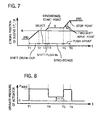
Fig. 6 which shows a shift/select pattern of the operate lever,Fig. 7 which shows a stroke position of thesleeves Fig. 8 which shows an operate pressure of an actuator which actuates the sleeves. - In the synchromesh-type transmission, as shown in
Fig. 5 , the select member is engaged with theshift fork 31 in the 2nd-speed condition prior to the speed-change, and thesleeve 17 of thesynchro mechanism 15 is shifted leftwardly. To the contrary, thesleeve 18 of thesynchro mechanism 16 is positioned in the nuetral position. For speed-changing from a 2nd shift to a 3rd shift, as shown inFig. 6 , the operate lever is shifted from a 2nd shift position to a nuetral position N, then selected from a position corresponding to a 1st shift and 2nd shift to a position corresponding to a 3rd shift and a 4th shift, and then shifted from the neutral position N to a 3rd shift position. - When the operate lever is shifted from the 2nd shift position to the neutral position N at the time T1 in
Fig. 7 , an operate force directed rightwardly inFig. 5 is applied to thesleeve 17 via the select member and shiftfork 31, so that thesleeve 17 slides over thegear piece 23 of the 2nd-shift gear 11 without recieving resistance to reach the neutral position N at the time T2. This time period (T1 - T2) is called a "shift draw-out area"). - After the shift draw-out of the
sleeve 17, the operate lever is operated in the select direction so that the select member is disengaged from theshift lever 31 and is engaged with theshift lever 32 during a time period (T2 - T3) ofFig. 7 . Theshift fork 32, by a successive shift operation of the operate lever, starts to shift thesleeve 18 of thesynchro mechanism 16 rightwardly inFig. 5 at a time T3. As a result, the shift key, by cooperating with thesleeve 18, presses an end surface of thering 28. A time period (T 3 - T 4) when the shift key presses the end surface of thering 28 is called a "shift push-in (index) area". - As apparent from
Fig. 7 , thesleeve 17 shifts by a constant speed in the shift draw-out area (T1 - T2), and thesleeve 18 shifts by a constant speed in the shift push-in area (T 3 - T 4) but is stopped in the select area (T 2 - T 3). - At a time T 4 when the shift key does not follow the shift of the
sleeve 18, a chamfer of thespline 18a of thesleeve 18 starts to engage withouter teeth 28a of thering 28. A stroke position of thesleeve 18 corresponding to the time T4 is called a "synchronize start point (balk point)" where thesleeve 18 is stopped irrespective the force applied thereto. In the stroke position S of the balk point T4, thesleeve 18 presses thering 28 against thegear piece 24 and waits time T 5 when thegear piece 24 synchronizes with thesleeve 18 and thering 28 of low-speed rotation. This time period (T4 - T5) is called a "synchronize area" where thesleeve 18 is stopped. - When the
gear piece 24 synchronize with thesleeve 18 and thering 28, a rotation friction torque between thering 28 and thegear piece 24 is removed, so thatsleeve 18 as the shifting thereof pushes apart thering 28 and meshes with thedog teeth 24a of thegear piece 24. At this time, the rotate speed of thegear piece 24 and the 3rd-shift gear 12 is decreased to a value smaller than that upon the synchronization with thesleeve 18 due to drag torque thereof. For this reason, upon a re-synchronizing when thesleeve 18 meshes with thedog teeth 24a of thegear piece 24, the load applied from thegear piece 24 and the 3rd-shift gear 13 to thesleeve 18 varies suddenly. This stroke position of thesleeve 18 is called "two-shift input point". - The
sleeve 18, after having pushed apart thegear piece 24 by overcoming the load at the two-shift input point, receives a stop force from an end surface of the 3rd-shift gear 12 to stop at a stroke position corresponding to a time T6. This time period (T5 - T6) is called "push-apart area" in which thesleeve 18 shifts in a constant speed. Thereafter, thesleeve 18 is maintained at the 3rd-shift position by a predetermined lock mechanism which engages with theshift fork 32 and the operate lever. - The shifting of the
sleeves mechanisms WO97/05410 Fig. 8 , a control means including the controller,, adjusts an operate pressure of the actuator based on a vehicle condition or a speed-change process. - In detail, the control means sets an operate pressure in a max. value Pmax in the shift draw-out area (T1 - T2) of the
sleeve 17 and the shift push-in area (T3 - T4) of thesleeve 18 to shift thesleeves sleeve 18 with thering 28 etc. are started, the operate pressure of the actuator is decreased to an adjusted value P1 needed for the synchronizing to thereby press thesleeve 18 against thering 28 by a weaker force. Such weaker press force is convenient to extend an endurance character of construction members of the transmission and to reduce or prevent a noise or a speed change shock occurred upon the synchronizing. In a push-apart area (T5 - T6) after a time T5 when the synchronization has been completed and a predetermined time period after having detected a stop point, the operate pressure for the actuator is set in the max. value Pmax again to shift thesleeve 18 by the large force and in the high speed. In a time period before the speed-change operation and a time period after the stop point, the operate pressure of the actuator is set in zero. - However, in the conventional control manner by the control means for the actuator, the operate pressure of the actuator is maintained in the max. value during the shift draw-out area (T1 -T2) of the
sleeve 17, select area and the shift push-in area (T3 -T4) of thesleeve 18, and maintained in the max. value at the balk point B where thesleeve 18 starts to synchronize with thering 28. Therefore, thesleeve 18 abuts against thering 28 by the large drive force and in the high speed to thereby generate the speed-change shock and the noise. If the operate pressure of the actuator upon the shifting push-in of thesleeve 18 is decreased, there is fear that the shift push-in of thesleeve 18 may become inaccurate or longer time is required for the shift push-in of thesleeve 18. On the other hand, the operate pressure of the actuator is adjusted (decreased) to the adjusted value P1 to thereby decrease the drive force of thesleeve 18 correspondingly. However, the speed-change shock or noise may be generated even in this adjusted value P1 depending on the rotate speed of thegear piece 24 and the like. - In addition to the speed change from the 2nd shift to the 3rd shift via the select operation, in a speed change from the 4th shift to the 5th shift via a select operation and a shift-down operation via the select operation, the speed-change shock or the noise may occur. Same problem may occur in a speed change (shift-up and shift-down) without the select operation. That is, the shock/noise may occur in all kinds of the shift operation.
-
Document EP 0 552 866 A1 discloses a variable pressure range section actuator piston and a control method for controlling a shift actuator associated with a synchronized jaw clutch for selectively engaging and disengaging a selectable ratio in a first transmission section of a compound transmission. -
Document EP 0 750 140 A3 discloses a gear shift control system for a synchromesh unit, particularly suitable for controlling a synchromesh in a forward/reverse pre-select gear change system. - In view of the above circumstances, the present invention intends to provide a shift control apparatus for transmission which can reduce or prevent the speed-change shock and/or noise at the balk point where the sleeve engages with the ring in the shift push-in process, and in the two-shift input point where the sleeve pushes apart the ring and engages with the gear piece in the push-apart area.
- In order to achieve the above object, a shift control apparatus for a transmission according to
claim 1 is submitted. - According to the shift control apparatus for transmission, the drive force of the sleeve is decreased at least at the timing just before the balk point where the sleeve engages with the ring in the shift push-in area, so the speed change shock and noise at the balk point can be reduced. Also, as the occasion demands, the drive force of the sleeve can be decreased at the timing just before the two-shift input point where the sleeve pushes apart the ring and engages with the gear piece.
- The present invention can have following embodying modes.
- Three sets of synchro mechanisms can be provided when the transmission includes five forward shifts and one backward shift, while two sets of synchro mechanisms can be provided when the transmission includes three forward shifts and one backward shift. The numbers of the sleeves correspond to the numbers of sets of the free-rotate gears, so three sleeves or two sleeves are provided for three sets or two sets of the free-rotate gears. As the actuator(s), one actuator for the shift operation and one actuator for the select operation can be provided, or an actuator for the shift operation and an actuator for the select operation can be made integral. In the transmission including five forwards shifts and one backward shift for example, the shift control of the present invention can be applied to the speed-change between the 2nd shift and the 3rd shift or between the 4th shift and the 5th shift via the select operation, and to the speed-change between the 1st shift and the 2nd shift or between the 3rd shift and the 4th shift without the select operation.
- A target speed-change shift can be set by an operate lever handled by a driver, a lever switch contacts of which are opened/closed, or a button-type switch.
- The actuator can be an electric type and hydraulic type. The electric-type actuator can be comprised of for example an electric motor, a pinioin attached to an output shaft of the motor and an a rack meshed with the pinion and connected to the shift fork. On the other hand, the hydraulic-type actuator can be comprised of for example a master valve, proportional flow-amount valve communicated with the master valve, and an oil cylinder or an air cylinder communicated with the master cylinder and the proportional flow-amount valve and connected with the sleeve. A rod of the oil cylinder or air cylinder is connected with the shift fork.
- An operate force of the hydraulic-type actuator is controlled in a first operate pressure at the start or beginning of speed-change, and in a second operate pressure smaller than the first operate pressure just before the balk point. The operate force of the actuator can be increased from the second operate pressure to a third operate pressure larger than the second operate pressure just before the two-shift input point. The hydraulic cylinder of the actuator, in the transmission including the fire forward shifts and one backward shift for example, shifts draw-out one sleeve from the 2nd shift position or the 4th shift position by the movement from a retract position to an advance position, and shifts push-in the same or other sleeve to a 1st shift position, a 3rd shift position or a 5th shift position by a movement from the neutral position to the advance position in the speed-change in minus (-) direction in
Fig. 6 . - The sleeve is driven by the actuator, and the drive force thereof is adjusted to a third drive force smaller than a first drive force but is larger than a second drive force during a second time period before the two-shift input point. Also, the sleeve moves in a first speed at the beginning of the speed-change, moves in a second speed smaller than the first speed when the drive force is decreased to the second drive force, and moves in a third speed larger than the second speed when the drive force is increased to the third drive force. In the hydraulic-type actuator, the drive force of the sleeve is determined in connection with an oil source and a master valve of the actuator, and the move speed of the sleeve is determined in connection with the oil source, the master valve and a proportional flow-amount valve.
- A first predetermined time period for applying the second drive force can continue until the balk point of the sleeve is detected, while a second predetermined time period for applying the third drive force can continue until the sleeve moves beyond the stop point where the sleeve abuts onto an end surface of the free-rotate gear.
- The electric control means can be comprised of an extra electric circuit which controls an amplify degree of current flown to an actuator, and a computer-type controller such as a ECU or an extro electric circuit generating a current shape and controls the actuator. On the other hand, the hydraulic actuator can be comprised of a hydraulic control circuit, and a computor-type controller such as a ECU or an extra electric circuit to control electro-magnetic valve disposed in the hydraulic control circuit.
- The control means can, for example, controls the controller of the electric actuator the electro-magnetic valve so that the operate pressure of the actuator i.e. the drive force of the sleeve is set in the max. value at the beginning of the speed-change, decreased to the min. value before the balk point where the sleeve meshes with the synchronize ring, increased to a first value during the synchronize area after the synchronize area, returned to the max. value at the beginning of the push-apart operation, and decreased to a second value higher than the first value before the two-shift input point where the sleeve meshes with the free-rotate gear.
- Here, the control means can decrease the operate pressure of the shift cylinder i.e. the drive force and the move speed of the sleeve by controlling the current flown to the electro-magnetic valve of the actuator, or can decrease only the move speed of the sleeve without changing the operate pressure of the shift cylinder i.e. the drive force of the sleeve. The shock and the noise felt by the passenger is generated by vibration of a vehicle, and quality thereof is mainly determined by an amplitude and a frequency thereof. Decrease of the drive force of the sleeve contributes to decrease the amplitude, while decrease of the move speed of the sleeve contributes to decrease the frequency. In any way, there are band areas of the shock and the noise felt by the passenger, so the present invention intends to shift or offset such band areas.
-
-
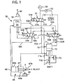
Fig. 1 is a constructive view of one embodiment of the present invention; -
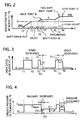
Fig. 2 is an operate view showing a stroke position of a sleeve of the above embodiment; -
Fig. 3 is an operate view showing a moving speed of sleeve of the above embodiment; -
Fig. 4 is an operate view showing an operate pressure of a select cylinder and a shift cylinder of the above embodiment; -
Fig. 5 is a skelton view showing a popular construction of synchromesh-type transmission; -
Fig. 6 is an explanatory view showing a popular operate pattern of an operate lever; -
Fig. 7 is an operate view showing a stroke position of the sleeve of a conventinal art; and -
Fig. 8 is an operate view showing an operate pressure of an actuator of a conventinal art. - Hereinafter, a preferred embodiment of the present invention will be explained with reference to attached
Figs. 1 to 4 . However, it is noted that this embodiment should not be interpreted to limit the present invention. - A shift control apparatus of this embodiment is comprised of an operate
lever 60 and aswitch 59; a control means 50 including amaster valve 51, a pair of proportional flow-amount valves controller 58; and an actuator including anoil pump 55 driven by an electric motor (not shown), anaccumulator 56, aselect cylinder 65 and ashift cylinder 70 etc., and drives the shifting of thesleeves 17 of thesynchro mechanism 15 and thesleeves 18 of thesynchro mechanism 16 shown inFig. 5 . - The
master valve 51 is a solenoid-type pressure control valve which outputs a pressure proportional to a solenoid current applied, and having asolenoid 51a, aleft position 51b, a right position 51c and a neutral position (not shown). Themaster valve 51 is switched to theleft position 51b and the right position 51c depending on a current applied to thesolenoid 51a by an activation of thesolenoid 51a to output a presssure proportional to the value of current, and is switched to the neutral position by an inactivation (off-condition) of thesolenoid 51a to thereby interrupt the supplying of the oil. - Each of the proportional flow-
amount valves solenoid left position left position solenoid master valve 51 in which the current is flown in themaster valve 51 and the pressure oil is supplied (on-condition). Themaster valve 51 and the proportional flow-amount 0valves passages - The
controller 58 is comprised of a ECU and the like, and recognizes a target or aimed speed-change shift by a signal inputted from aswitch 59 switched by an operate (manual) lever provided near a driver's seat. Thecontroller 58 controls a current amount supplied to the electric motor of thepump 55, and thesolenoids master valve 51 and the proportional flow-amount valves select cylinder 65 and ashift cylinder 70 corresponding to the speed-change shift. - The
controller 58 activates thesolenoid 51a of themaster cylinder 51 based on the speed-change signal to switch theleft position 51b and the right position 51c depending on the current applied to thesolenoid 51a to thereby vary the pressure value. Thus, the pressure oil is supplied from theaccululator 56 to the proportional flow-amount values passages controller 58 inactivates thesolenoid 51a of themaster valve 51 based on the speed-change signal to switch themaster valve 51 to the neutral position. In this condition, the supplying of the pressure oil is interrupted by themaster valve 51, and the pressure oil is not supplied to a right (front)pressure chamber 66b of theselect cylinder 65 and a lower (front)pressure chamber 71b of theshift cylinder 70. A left (rear)pressure chamber 66a of theselect cylinder 65 and an upper (rear)pressure chamber 71a of theshift cylinder 70 are communicated with theleft positions amount valves solenoids pressure chambers left positions select cylinder 65 and theshift cylinder 70 are not shifted. - The
select cylinder 65 is provided for driving the select member engaged with one of theshift forks cylinder 66 and apiston 67. Aleft pressure chamber 66a of theselect cylinder 65 is communicated with the proportional flow-amount valve 52 via a passage 55c and aright pressure chamber 66b thereof is communicated with themaster valve 51 via apassage 55d. In the activated condition of themaster valve 51, the pressure oil is always supplied to theright pressure chamber 66b via thepassage 55d. So, when the pressure oil is applied from the proportional flow-amount valve 52 to theleft pressure chamber 66a through a passage 55c, thepiston 67 moves forwardly (in plus(+) X direction) by difference of pressure receive area, and when the reserve pressure is applied from the proportional flow-amount valve 52 thepiston 67 moves rearwardly (in minus (-) X direction). Thepiston 67 cause the select member to engage with theshift fork 32 when it is located in a rearmost position (therod 67 is retracted to the max. extent), to engage with theshift fork 31 when it is located in the neutral position, and to engage with a shift fork (not shown) for a 5th-shift and rearward shift when it is located in the frontmost position. - The
shift cylinder 70 is provided for shifting the select member in the shift direction and shifting theshift fork cylinder 71 and apiston 72. Anupper pressure chamber 71a of theshift cylinder 70 is communicated with the proportional flow-amount valve 53 via apassage 55e and alower pressure chamber 71b thereof is communicated with themaster valve 51 via apassage 55d. In the activated condition of themaster valve 51, the pressure oil is always supplied to thelower pressure chamber 71b of theshift cylinder 70 via thepassage 55d. So, when the pressure oil is applied from the proportional flow-amount valve 53 to theupper pressure chamber 71a through apassage 55e, thepiston 72 moves forwardly (in plus(+) X direction) by difference of pressure receive area, and when the reserve pressure oil is applied from the proportional flow-amount valve 53 thepiston 72 moves rearwardly (in minus (-) X direction). Thepiston 72 shifts theshift forks rod 72 is retracted to the max.extent), and moves theshift fork - An advance position and a retract position of the
piston rods select cylinder 65 and theshift cylinder 70 are detected byposition sensors controller 58. - When the speed-change shift of the cynchromesh-type transmission shown in
Fig. 5 is shifted, themaster valve 51, the proportional flow-amount valves actuator 58 in the flowing manner. Here, a shift-up operation from the 2nd shift to the 3rd shift performed by shifting thesleeves synchro mechanisms select cylinder 65, theshift cylinder 70, the select member, and theshift forks - In the 2nd-shift condition, no current is supplied from the
controller 58 to thesolenoid 51a, and themaster valve 51 is brought to the neutral position. So, as shown inFig. 1 , thepiston rods select cylinder 65 and theshift cylinder 70 are brought to a free condition. Theshift fork 31 ofFig. 5 is held by the lock mechanism and causes thesleeve 17 of thesynchro mechanism 15 to engage with thegear piece 23. - From this 2nd-shift condition, the operate
lever 60 is operated along the shift pattern ofFig. 6 . Based on operation o the operatelever 60, thecontroller 58 controls themaster valve 51 and the proportional flow-amount valves shift cylinder 70 shifts the shift fork engaged by thesleeve 17, theselect cylinder 65 selects (moves) the select member for causing it to engage with theshift fork 32, and theshift cylinder 70 shifts theshift fork 32. Concretely, this speed-change process is set by setting a basic wave shape of the current supplied from thecontroller 58 to thesolenoids amount valves solenoids position sensors - Next, each step for the speed change will be explained.
- Based on the shift operation of the operate
lever 60 by the driver from the 2nd-shift position to the neutral position N at a time T1 inFig. 1 , thecontroller 58 supplies the current to thesolenoids master valve 51 and proportionalflow amount valve 53 to supply the pressure oil of the max. amount from beginning of speed-change, but increases/decreases the current supplied to thesolenoid 52a of the proportional flow-amount valve 52. As a result of the current increase/decrease thesolenoid 52a, the proportional flow-amount valve 52 is switched to theleft position 52b and the right position 52c repeatedly to supply the pressure oil to the left andright pressure chambers select cylinder 65. When the proportional flow-amount valve 52 is switched to theleft position 52b thepiston 67 of theselect cylinder 65 moves in the +X direction due to a difference of pressure receive areas between area of theleft pressure chamber 66a to which the pressure oil of themaster cylinder 51 is applied and area of theright pressure chamber 66b; while when it is switched to the right position 52c thepiston 67 moves in the -X direction due to differenct of a pressure difference between pressure of theleft pressure chamber 66a to which the pressure oil of themaster cylinder 51 is applied and pressure of theright pressure chamber 66b. Thus, in both cases, thepiston 67 of theselect cylinder 65 is moved to the neutral position to hold the select member engaging with theshift fork 31 in the condition in which thesolenoid 52a reveals a current value located between the current values of theleft position 52b and the right position 52c. Hereinafter, this condition of this proportional flow-amount-valve 52 is called "hold", which is same for the proportional flow-amount valve 53. As a result of the max. amount of the pressure oil by themaster valve 51 and the proportional flow-amount valve 53, the pressure oil is supplied via thepassage 55e to theupper pressure chamber 71a as shown inFig. 4 , so that the operate pressure of theshift cylinder 70 is set in the max. value Pmax. Accordingly, thepiston 72 moves in the +Y direction to advance theshift fork 31 engaged with the select member, and theshift fork 31 ofFig. 5 in turn moves thesleeve 17 of thesynchro mechanism 15 by the drive force Qmax as shown inFig. 4 , and by the speed V1 as shown inFig. 3 . Thus, thesleeve 17 is subjected to the shift draw-out operation (refer to the time period (T1 - T 2) inFig. 2 ), and shifted to the neutral position N. - When the position signal of the
position sensor 73 outputs the neutral position N of thepiston 72 of theshift cylinder 70, thecontroller 58 based on it sets the proportional flow-amount valve 52 in a current decrease condition (right position 52c), and the proportional flow-amount valve 53 in a current increase/decrease condition or a hold condition. As a result of the current decrease of the proportional flow-amount valve 52, thepiston 67 of theselect cylinder 65 moves in the -X direction for causing the select member to engage with theshift fork 32 inFig. 5 . On the other hand, as a result of the current increase/decrease or the hold of the proportional flow-amount valve 53, the pressure oil is supplied to theupper pressure chamber 71a and thelower pressure chamber 71b of theshift cylinder 70. Thus, thepiston 72 is held in the neutral position, and has the speed of zero as shown inFig. 3 . In this way, a select operation (T2 - T3) ofFig. 2 is performed. - When the
piston 67 of theselect cylinder 65 retracts to the rearmost (leftmost inFig. 1 ) position, thecontroller 58 based on it recognizes the completion of the select operation, that is, the time T 3 for the shift push-in of thesleeve 18 by the position signal of theposition sensor 68. In the shift push-in process, thecontroller 58 holds the current increase condition (leftposition 53b) of themaster valve 51 and the proportional flow-amount valve 53. Thus, the pressure oil is supplied via thepassage 55e to theupper pressure chamber 71a of theshift cylinder 70 to advance thepiston 72 in the +Y direction so that thesleeve 18 inFig. 5 is pushed against thering 28. - In this embodiment, at a time T3' before a time T 4 (refer to
Fig. 6 ) when a balk point B(a point when thesleeve 18 abuts onto theouter teeth 28a of thering 28 in course of the advance of thepiston rod 72a of theshift cylinder 70 in the +Y direction) is detected by theposition sensor 73 by a predetermined distance, thecontroller 58 decreases the current supplied to thesolenoid 51a of themaster valve 51. The distance or the time period between the time T3' and the balk point is set, for example, based on experience or actual result obtained from the design value, variation of the input shaft and the output shaft, in view of the response time of themaster valve 51 and the proportional flow-amount valve amount valve 53 to theupper pressure chamber 71a of theshift cylinder 70 is decreased, so that the operate pressure of theshift cylinder 70 is set in an operate pressure P2 which is smaller than Pmax (P2 < Pmax) between the time T3 ' and the time T4 ' including the balk point B. - As a result, the drive force for the
shift fork 32 and thesleeve 18 in the time period (T 3 ' - T4 ') is set in a drive force Q2 which is smaller than the drive force Qmax. As shown inFig. 3 , thesleeve 18 has a speed V 2 which is smaller than the speed V 1. The distance or the time period between the time T 3 'and the balk point is set, for example, based on experience or actual result obtained from the design value, variation of the input shaft and the output shaft, in view of the response time of themaster valve 51, and the proportional flow-amount valve sleeve 18 can be engaged with theouter teeth 28a of thering 28 softly. Here, the time T4 ' is a timing after a predetermined time lapse when theposition sensor 73 detects the stroke position S of the balk point B. Also, in a time period (T3 - T3') the operate pressure of theshift cylinder 70 is set in the pressure P 2, and the drive force of thesleeve 18 is set in the speed Q2. - When the balk point B is detected by the
position sensor 73, thecontroller 58 based on it supplies more current to thesolenoid 51a of themaster valve 51 so that the operate pressure of theshift cylinder 70 is decreased to a pressure P1, and the drive force for thesleeve 18 is decreased to a force Q1. In this synchronize period (T4 ' - T5), thesleeve 18 maintains the pushed state onto the end surface of thering 28 by the drive force Q1 and is stopped (refer toFig. 3 ), and waits a time when the rotate speed of the 3rd-shift gear 12 comes close to that of thesleeve 18. - When the rotate speed between the
sleeve 18 and the 3rd-shift gear 12 is synchronized, thesleeve 18 can advances to the 3rd-shift position since thering 28 becomes to idly rotate. By the position signal of theposition sensor 73 corresponding to the advance position of thesleeve 18, thecontroller 58 supplies the most current to thesolenoid 51a of themaster cylinder 51. As a result, the operate pressure of theshift cylinder 70 in the time period (T5 - T5') is set in the pressure Pmax, and accordingly the drive force for thesleeve 18 is set in the force Qmax same as that in the shift draw-out process. Here, thesleeve 18 advances by a speed V1 as shown inFig. 3 . - When a position of the
sleeve 18 inFig. 5 before a position where thesleeve 18 pushed by the drive force Qmax engages with theteeth 24a of thegear piece 24 by a predetermined distance is detected by theposition sensor 73, thecontroller 58 based on it at a time T5' decreases the current supplied to thesolenoid 51a of themaster cylinder 51 again, until a time T6. This is for preventing the speed-change shock and noise at a two-shift input point C where thesleeve 18 engages with thegear piece 24, and a stop point D where thesleeve 18 abuts onto the 3rd-shift gear 12. The distance or the time period between the time T3 'and the balk point is set, for example, based on experience or actual result obtained from the design value, variation of the input shaft and the output shaft, in view of the response time of themaster valve 51 and the proportional flow-amount valve master valve 51 is select to be smaller than that at the above time T3', and therefore the value of the current at this time T5' is larger than that of the above time T3'. - Accordingly, the operate pressure P3 for the
shift cylinder 70 in the time period (T5 ' - T6) including the two-shift input point C and the stop point D is selected to be larger than the operate pressure P2 in the time period (T3' - T4') including the balk point B. Corresponding to it, the drive force Q3 for thesleeve 18 in the time period (T5' - T6) is selected larger than the drive force Q2 in the time period (T3' - T4'), and the move speed V3 of thesleeve 18 in the time period (T5' - T6) is selected faster than the move speed V 2 in the time period (T3' - T4') as shown inFig. 3 . These differences of the pressure and the force are provided because the speed-change shock and the noise occurred in the two-shift input point C is smaller than that occurred at the balk point B. - When the stop point D of the
sleeve 18 inFig. 4 is detected by theposition sensor 73, thecontroller 58 based on it stops the supplying of the current to themaster valve 51 and the proportional flow-amount valve 53, to thereby complete the speed-change process. - A Table 1 summarizes the operation of the
master valve 51, the proportional flow-amount valves select cylinder 65 and theshift cylinder 70 in each of the steps S1 to S6.<Table 1> step 51 52 53 65 70 1 ON increase /decrase or hold increase (max.) N up→ N 2 ON decrease increase /decrease or hold N→ left N 3 ON (decreased at T3') hold increase left N →down 4 ON (increased at T4') hold increase left N →down 5 ON (max.) hold increase left N→ down 6 ON (decreased at T5') hold increase left N → down
Claims (3)
- A shift control apparatus for a transmission including plural sets of paired free-rotate gears (11, 12, 13) mounted on a rotary shaft (30) corresponding to speed-change gears, plural sleeves (17, 18) each mounted on the rotary shaft (30) not to be rotated circumferentially and to be shifted axially thereof, plural sets of paired synchronize rings (27, 28, 29) disposed between each set of said free-rotate gears (11, 12, 13) and each of said sleeves, an actuator (65, 70) for moving each of said sleeves (17, 18), and a control means (50) for controlling said actuator (65, 70) based on a speed-change command, whereby a speed-change shift is changed by engaging said sleeve (17, 18) driven by said actuator (65, 70) with one of said synchronize rings (27, 28, 29) and said free-rotate gears (11, 12, 13), wherein
said control means (50) controls said actuator (65, 70) so that said sleeve (17, 18) is driven by a first drive force (Qmax) upon starting of a speed-change operation, and is driven by a second drive force (Q2) smaller than the first drive force at least during a first time period T3' to T4' from a time before a balk point B of said sleeve (17, 18) where said sleeve (17, 18) engages with said synchronize ring (27, 28, 29) in a shift push-in operation, and that said sleeve (17, 18) is driven by a third drive force (Q3) smaller than the first drive force during a second time period (T5' - T6) from a time (T5') before a two-shift input point of said sleeve (17, 18) where said sleeve (17, 18) engages with said free-rotate gear (11, 12, 13),
characterized by that
said control means (50) controls an operate pressure of said actuator so that a drive force of said sleeve is set in the max. force upon starting of a speed-change operation, in the min. force before said sleeve reaches to the balk point, in a first force larger than the min, force during a synchronize period after the balk point, in the max. force upon starting of a push-apart period, and in a second increased force larger than the first force before said sleeve reaches to a two-shift input point engaging with said free-rotate gear. - A shift control apparatus according to claim 1, wherein said control means stepwisely sets said drive force of said sleeve.
- A shift control apparatus according to claim 1 or 2, further including a second actuator for selecting one of said sleeve to be shifted push-in, prior to the shift push-in operation.
Applications Claiming Priority (2)
| Application Number | Priority Date | Filing Date | Title |
|---|---|---|---|
| JP14513199A JP4447070B2 (en) | 1999-05-25 | 1999-05-25 | Shift control device for transmission |
| JP14513199 | 1999-05-25 |
Publications (3)
| Publication Number | Publication Date |
|---|---|
| EP1055847A2 EP1055847A2 (en) | 2000-11-29 |
| EP1055847A3 EP1055847A3 (en) | 2002-12-04 |
| EP1055847B1 true EP1055847B1 (en) | 2008-08-20 |
Family
ID=15378134
Family Applications (1)
| Application Number | Title | Priority Date | Filing Date |
|---|---|---|---|
| EP00108249A Expired - Lifetime EP1055847B1 (en) | 1999-05-25 | 2000-04-14 | Shift control apparatus for transmission |
Country Status (4)
| Country | Link |
|---|---|
| US (1) | US6276224B1 (en) |
| EP (1) | EP1055847B1 (en) |
| JP (1) | JP4447070B2 (en) |
| DE (1) | DE60039938D1 (en) |
Families Citing this family (60)
| Publication number | Priority date | Publication date | Assignee | Title |
|---|---|---|---|---|
| US6579208B2 (en) * | 2000-01-18 | 2003-06-17 | Borgwarner, Inc. | Method and apparatus for providing synchronization of low to high shifts in a transfer case |
| JP3499190B2 (en) * | 2000-04-04 | 2004-02-23 | 株式会社日立製作所 | Automatic transmission |
| JP2001304390A (en) * | 2000-04-25 | 2001-10-31 | Mitsubishi Electric Corp | Control device for synchronous mesh automatic transmission |
| JP2002048225A (en) * | 2000-08-07 | 2002-02-15 | Aisin Ai Co Ltd | Transmission for synchromesh transmission |
| JP2002071019A (en) * | 2000-08-31 | 2002-03-08 | Aisin Ai Co Ltd | Control device for actuator used in transmission |
| GB0025000D0 (en) * | 2000-10-12 | 2000-11-29 | Luk Lamellen & Kupplungsbau | Hydraulic actuation systems |
| CN101334109B (en) * | 2000-10-20 | 2012-06-20 | 舍弗勒技术股份两合公司 | Motor vehicle with gearbox and method for operating a motor vehicle |
| AU2007200427B2 (en) * | 2000-10-20 | 2009-04-23 | Luk Lamellen Und Kupplungsbau Beteiligungs Kg | Motor vehicle with a gearbox and method for operating a motor vehicle |
| JP4940485B2 (en) * | 2000-10-20 | 2012-05-30 | シェフラー テクノロジーズ アクチエンゲゼルシャフト ウント コンパニー コマンディートゲゼルシャフト | Vehicle equipped with a transmission and method of operating the vehicle |
| JP2002147590A (en) * | 2000-11-09 | 2002-05-22 | Isuzu Motors Ltd | Transmission control device for transmission |
| GB2368886A (en) * | 2000-11-13 | 2002-05-15 | Luk Lamellen & Kupplungsbau | Automatic transmission with a hydraulic actuation system |
| JP3787492B2 (en) * | 2000-11-29 | 2006-06-21 | 株式会社日立製作所 | Automatic transmission control device and method |
| JP2002243028A (en) * | 2001-02-15 | 2002-08-28 | Hitachi Ltd | Control device and control method for automatic transmission |
| DE10150720C1 (en) * | 2001-10-13 | 2003-06-12 | Daimler Chrysler Ag | Device having a unit for influencing a drive train, transmission series and method |
| FR2835030B1 (en) * | 2002-01-22 | 2005-05-06 | Valeo | METHOD AND DEVICE FOR CONTROLLING THE TRANSMISSION OF SPEEDS IN A GEARBOX OF A MOTOR VEHICLE |
| DE10312400A1 (en) * | 2002-03-21 | 2003-10-02 | Luk Lamellen & Kupplungsbau | Electric actuator for automatic gearbox uses synchronous control voltage delivered to achieve synchronisation of gears |
| US6694834B2 (en) * | 2002-03-22 | 2004-02-24 | New Venture Gear, Inc. | Control system for transfer case range shift |
| JP4502103B2 (en) * | 2002-03-27 | 2010-07-14 | スズキ株式会社 | Automatic transmission |
| EP1499820B1 (en) * | 2002-04-10 | 2008-10-01 | LuK Lamellen und Kupplungsbau Beteiligungs KG | Gearbox actuator comprising a bearing for the gearshift rails |
| JP2003314678A (en) * | 2002-04-25 | 2003-11-06 | Hitachi Ltd | Vehicle control method and control device |
| US6883394B2 (en) * | 2002-10-15 | 2005-04-26 | Borgwarner, Inc. | Method for controlling the positioning of the synchronizers of a dual clutch transmission |
| FR2849129B1 (en) * | 2002-12-19 | 2005-10-21 | Renault Sa | METHOD AND DEVICE FOR DRIVING A TRANSMISSION REPORTING ENGAGEMENT SYSTEM IN A ROBOTIC MECHANICAL TRANSMISSION |
| DE10302051A1 (en) * | 2003-01-21 | 2004-08-05 | Daimlerchrysler Ag | Control system for a shift drum of a gear change transmission of a motor vehicle |
| GB0307118D0 (en) * | 2003-03-27 | 2003-04-30 | Ricardo Uk Linmited | Method for controlling a transmission of a vehicle |
| GB0307117D0 (en) * | 2003-03-27 | 2003-04-30 | Ricardo Uk Linmited | Method for controlling a transmission of a vehicle |
| JP2005226687A (en) * | 2004-02-10 | 2005-08-25 | Aisin Ai Co Ltd | Automatic transmission for vehicle |
| JP2007024247A (en) * | 2005-07-20 | 2007-02-01 | Hino Motors Ltd | Transmission |
| DE102006016414A1 (en) | 2006-04-07 | 2007-10-11 | Zf Friedrichshafen Ag | Method and device for controlling a fluid-operated control system |
| US7845250B2 (en) * | 2006-05-01 | 2010-12-07 | Richmond Gear, Inc. | Transmission apparatus |
| FR2904674B1 (en) * | 2006-08-01 | 2008-10-17 | Peugeot Citroen Automobiles Sa | METHOD FOR DETERMINING THE POSITIONS OF BEGINNING AND COMPLETING A CRAB AND GEARBOX ESTIMATING A POSITION OF BEGINNING AND END OF CRABOTAGE AT THE PASSAGE OF A REPORT |
| FR2905438B1 (en) * | 2006-09-05 | 2008-10-17 | Peugeot Citroen Automobiles Sa | METHOD FOR CONTROLLING A DEVICE FOR COUPLING TWO CRABOTS WITH REDUCED CRABTIZING TIME |
| FR2905437B1 (en) * | 2006-09-05 | 2008-10-17 | Peugeot Citroen Automobiles Sa | METHOD FOR CONTROLLING A COUPLING DEVICE CONTROLLING TWO CRABOTS. |
| JP4341687B2 (en) * | 2007-03-19 | 2009-10-07 | 株式会社日立製作所 | Control device and control method for automatic transmission |
| EP2019230A1 (en) * | 2007-07-25 | 2009-01-28 | MAGNETI MARELLI POWERTRAIN S.p.A. | Servo-assisted mechanical gearbox with hydraulic actuation of the synchronizers |
| EP2065624B1 (en) * | 2007-11-28 | 2010-03-03 | Magneti Marelli S.p.A. | A method of driving an hydraulic actuator by means of a pressure-controlled proportioning solenoid valve |
| US8376906B2 (en) * | 2008-12-09 | 2013-02-19 | Borgwarner Inc. | Automatic transmission for a hybrid vehicle |
| GB2470016A (en) * | 2009-05-05 | 2010-11-10 | Gm Global Tech Operations Inc | Method of reducing torque shock during a gear shift |
| CN102459965B (en) | 2009-06-29 | 2014-11-05 | 博格华纳公司 | Hydraulic valve for use in a control module of an automatic transmission |
| US8560192B2 (en) * | 2010-04-15 | 2013-10-15 | GM Global Technology Operations LLC | Control system and method for shift fork position in dual clutch transmissions |
| US8504267B2 (en) | 2010-04-15 | 2013-08-06 | GM Global Technology Operations LLC | Control system and method for synchronization control in dual clutch transmissions |
| US8844393B2 (en) * | 2010-04-15 | 2014-09-30 | GM Global Technology Operations LLC | Fork position and synchronization control in a dual clutch transmission using pressure control solenoids |
| EP2650560B1 (en) | 2010-11-19 | 2020-10-21 | Ikeya Formula Co., Ltd. | Transmission and shift control system |
| DE102011007107B4 (en) | 2011-04-11 | 2023-11-02 | Zf Friedrichshafen Ag | Method for controlling an automated manual transmission |
| DE102011007105A1 (en) * | 2011-04-11 | 2012-10-11 | Zf Friedrichshafen Ag | Method for controlling an automated manual transmission |
| KR101305852B1 (en) * | 2011-06-09 | 2013-09-06 | 현대자동차주식회사 | Transmission Control Method for Vehicle |
| KR101305866B1 (en) * | 2011-06-09 | 2013-09-09 | 현대자동차주식회사 | Transmission Control Method for Vehicle |
| CN104395648B (en) | 2012-03-23 | 2017-06-30 | 环太平洋工程产品(1987)有限公司 | Double-clutch type power transmission with the alternative moment of torsion transmission path for providing alternative gearratio |
| WO2013138942A1 (en) | 2012-03-23 | 2013-09-26 | Pacific Rim Engineered Products (1987) Ltd. | Gear engagement mechanism for transmissions and related methods |
| JP5895702B2 (en) * | 2012-05-18 | 2016-03-30 | いすゞ自動車株式会社 | Vehicle transmission |
| JP6190117B2 (en) * | 2013-02-07 | 2017-08-30 | クノールブレムゼ商用車システムジャパン株式会社 | Transmission control device and transmission control method for transmission |
| JP6000178B2 (en) * | 2013-03-29 | 2016-09-28 | 本田技研工業株式会社 | Vehicle transmission |
| FR3018888B1 (en) * | 2014-03-19 | 2017-08-25 | Peugeot Citroen Automobiles Sa | METHOD AND DEVICE FOR CONTROLLING THE MOVEMENT OF THE FORKS OF A ROBOTIC GEARBOX BY REASSIGNING |
| US9360109B2 (en) | 2014-04-16 | 2016-06-07 | GM Global Technology Operations LLC | Method of controlling a synchronizer actuator fork of a transmission |
| CN106415081B (en) * | 2014-06-16 | 2018-12-11 | 沃尔沃卡车集团 | Method for controlling the actuator of transmission for vehicles |
| DE102016217096A1 (en) * | 2016-09-08 | 2018-03-08 | Audi Ag | Method for synchronizing two drive elements of a drive train of a motor vehicle, and drive train for a motor vehicle |
| SE541436C2 (en) * | 2016-12-21 | 2019-10-01 | Scania Cv Ab | A method and a system for controlling a synchromesh arrangement |
| JP7099410B2 (en) | 2019-06-28 | 2022-07-12 | トヨタ自動車株式会社 | Synchronous meshing mechanism control device |
| KR102341627B1 (en) * | 2020-08-18 | 2021-12-22 | (주)엠피에스코리아 | A PNEUMATIC ACTUATING DEVICE FOR ACTUATION TO BASED Dog clutch in manual transmission |
| DE102021210722A1 (en) | 2021-09-27 | 2023-03-30 | Zf Friedrichshafen Ag | Shifting system for a transmission |
| FR3140144A1 (en) * | 2022-09-27 | 2024-03-29 | Psa Automobiles Sa | CONTROL OF SILENT SHIFT OF A GEAR IN A CONTROLLED GEARBOX OF A VEHICLE |
Family Cites Families (13)
| Publication number | Priority date | Publication date | Assignee | Title |
|---|---|---|---|---|
| DE2136960B2 (en) * | 1971-07-23 | 1978-07-13 | Ardie-Werk Gmbh, 8500 Nuernberg | Device for switching gear change transmissions, in particular for motor vehicles |
| FR2233893A5 (en) * | 1973-06-18 | 1975-01-10 | Berliet Automobiles | |
| JPS58149449A (en) * | 1982-03-02 | 1983-09-05 | Toyota Motor Corp | Speed change controlling method of vehicular automatic transmission |
| JPH01238741A (en) * | 1988-03-17 | 1989-09-22 | Diesel Kiki Co Ltd | Fluid pressure actuator |
| US5167311A (en) * | 1989-09-26 | 1992-12-01 | Zexel Corporation | Transmission control system with gear shift failure detection |
| US5224392A (en) * | 1992-01-23 | 1993-07-06 | Eaton Corporation | Variable pressure range section actuator piston |
| GB9512838D0 (en) * | 1995-06-23 | 1995-08-23 | Massey Ferguson Sa | Synchromesh control apparatus and method |
| DE19526273C2 (en) * | 1995-07-19 | 1999-12-09 | Ford Werke Ag | Automatically switchable countershaft transmission, especially for motor vehicles |
| GB2308413B (en) | 1995-07-26 | 1999-09-01 | Ap Kongsberg Ltd | Ratio selector mechanisms |
| KR100198705B1 (en) * | 1996-09-17 | 1999-06-15 | 류정열 | Shifting device for electrical vehicle |
| JPH1122816A (en) * | 1997-06-30 | 1999-01-26 | Aisin Seiki Co Ltd | Transmission control device for synchromesh transmission |
| JPH11287321A (en) * | 1998-04-01 | 1999-10-19 | Aisin Ai Co Ltd | Hydraulic circuit of shift actuator for automatic transmission |
| JP3313327B2 (en) * | 1998-07-30 | 2002-08-12 | アイシン・エーアイ株式会社 | Shift control device for synchromesh transmission |
-
1999
- 1999-05-25 JP JP14513199A patent/JP4447070B2/en not_active Expired - Fee Related
-
2000
- 2000-04-12 US US09/547,853 patent/US6276224B1/en not_active Expired - Lifetime
- 2000-04-14 DE DE60039938T patent/DE60039938D1/en not_active Expired - Lifetime
- 2000-04-14 EP EP00108249A patent/EP1055847B1/en not_active Expired - Lifetime
Also Published As
| Publication number | Publication date |
|---|---|
| US6276224B1 (en) | 2001-08-21 |
| EP1055847A2 (en) | 2000-11-29 |
| EP1055847A3 (en) | 2002-12-04 |
| JP2000337487A (en) | 2000-12-05 |
| JP4447070B2 (en) | 2010-04-07 |
| DE60039938D1 (en) | 2008-10-02 |
Similar Documents
| Publication | Publication Date | Title |
|---|---|---|
| US6276224B1 (en) | Shift control apparatus for transmission | |
| EP2024661B1 (en) | Dual clutch powershift transmission with transfer shaft | |
| KR100318246B1 (en) | Automatic mechanical shift control device and method | |
| EP1961996B1 (en) | Speed change system for working vehicle | |
| EP1467128B1 (en) | Multistage automatic transmission | |
| JPH11325228A (en) | Jaw clutch connection control device and control method therefor | |
| US5433125A (en) | Gear shift mechanism of a motor vehicle transmission | |
| JPS6333586B2 (en) | ||
| JPH0640274A (en) | Method and device for control of automatic splitter shift | |
| JPH04302774A (en) | Controller for shifting input section of transmission and control method thereof | |
| JPH11230332A (en) | Fluid auxiliary shift device and method of mechanical transmission | |
| US20020000133A1 (en) | Shift-assisting device for a transmission | |
| EP1160487B1 (en) | Control device and method for automatic transmission for automatically shifting synchromesh type gear transmission | |
| JPH11336885A (en) | Method and apparatus for controlling range shift in vehicle transmission system | |
| JP3312220B2 (en) | Synchronous splitter unit protection apparatus and method | |
| US20020053248A1 (en) | Shift control device for a transmission | |
| US6648795B2 (en) | Transmission system for vehicle | |
| JP4837329B2 (en) | Automatic manual transmission start control device | |
| EP1156237B1 (en) | Shift-assisting device for a transmission | |
| GB2433301A (en) | A method of controlling a powershift transmission during change-of-mind shifts | |
| DE69908692T2 (en) | Adaptive switching force control of an actuator for a splitter transmission | |
| JP2002188715A (en) | Control device for synchronous mesh automatic transmission | |
| EP0628754A1 (en) | Auxiliary transmission system and input splitter therefor | |
| GB2471989A (en) | Speed and pressure control of a synchronizer in a gearbox | |
| CN108730431B (en) | Double break transmission reverser with break synchronizer |
Legal Events
| Date | Code | Title | Description |
|---|---|---|---|
| PUAI | Public reference made under article 153(3) epc to a published international application that has entered the european phase |
Free format text: ORIGINAL CODE: 0009012 |
|
| 17P | Request for examination filed |
Effective date: 20000414 |
|
| AK | Designated contracting states |
Kind code of ref document: A2 Designated state(s): AT BE CH CY DE DK ES FI FR GB GR IE IT LI LU MC NL PT SE |
|
| AX | Request for extension of the european patent |
Free format text: AL;LT;LV;MK;RO;SI |
|
| PUAL | Search report despatched |
Free format text: ORIGINAL CODE: 0009013 |
|
| AK | Designated contracting states |
Kind code of ref document: A3 Designated state(s): AT BE CH CY DE DK ES FI FR GB GR IE IT LI LU MC NL PT SE |
|
| AX | Request for extension of the european patent |
Free format text: AL;LT;LV;MK;RO;SI |
|
| RIC1 | Information provided on ipc code assigned before grant |
Free format text: 7F 16H 61/28 A, 7F 16H 61/30 B, 7F 16H 61:04 Z |
|
| 17Q | First examination report despatched |
Effective date: 20030218 |
|
| AKX | Designation fees paid |
Designated state(s): DE GB IT |
|
| 17Q | First examination report despatched |
Effective date: 20030331 |
|
| GRAP | Despatch of communication of intention to grant a patent |
Free format text: ORIGINAL CODE: EPIDOSNIGR1 |
|
| RIC1 | Information provided on ipc code assigned before grant |
Ipc: F16H 61/04 20060101ALI20080131BHEP Ipc: F16H 61/28 20060101AFI20080131BHEP Ipc: F16H 61/30 20060101ALI20080131BHEP |
|
| GRAS | Grant fee paid |
Free format text: ORIGINAL CODE: EPIDOSNIGR3 |
|
| GRAA | (expected) grant |
Free format text: ORIGINAL CODE: 0009210 |
|
| AK | Designated contracting states |
Kind code of ref document: B1 Designated state(s): DE GB IT |
|
| REG | Reference to a national code |
Ref country code: GB Ref legal event code: FG4D |
|
| REF | Corresponds to: |
Ref document number: 60039938 Country of ref document: DE Date of ref document: 20081002 Kind code of ref document: P |
|
| PLBE | No opposition filed within time limit |
Free format text: ORIGINAL CODE: 0009261 |
|
| STAA | Information on the status of an ep patent application or granted ep patent |
Free format text: STATUS: NO OPPOSITION FILED WITHIN TIME LIMIT |
|
| 26N | No opposition filed |
Effective date: 20090525 |
|
| PGFP | Annual fee paid to national office [announced via postgrant information from national office to epo] |
Ref country code: GB Payment date: 20180329 Year of fee payment: 19 |
|
| PGFP | Annual fee paid to national office [announced via postgrant information from national office to epo] |
Ref country code: DE Payment date: 20180404 Year of fee payment: 19 |
|
| PGFP | Annual fee paid to national office [announced via postgrant information from national office to epo] |
Ref country code: IT Payment date: 20180420 Year of fee payment: 19 |
|
| REG | Reference to a national code |
Ref country code: DE Ref legal event code: R119 Ref document number: 60039938 Country of ref document: DE |
|
| GBPC | Gb: european patent ceased through non-payment of renewal fee |
Effective date: 20190414 |
|
| PG25 | Lapsed in a contracting state [announced via postgrant information from national office to epo] |
Ref country code: GB Free format text: LAPSE BECAUSE OF NON-PAYMENT OF DUE FEES Effective date: 20190414 Ref country code: DE Free format text: LAPSE BECAUSE OF NON-PAYMENT OF DUE FEES Effective date: 20191101 |
|
| PG25 | Lapsed in a contracting state [announced via postgrant information from national office to epo] |
Ref country code: IT Free format text: LAPSE BECAUSE OF NON-PAYMENT OF DUE FEES Effective date: 20190414 |