EP1055600B1 - Strukturbauteil aus einem Verbundwerkstoff mit eingebauter Dämpfung - Google Patents
Strukturbauteil aus einem Verbundwerkstoff mit eingebauter Dämpfung Download PDFInfo
- Publication number
- EP1055600B1 EP1055600B1 EP00110232A EP00110232A EP1055600B1 EP 1055600 B1 EP1055600 B1 EP 1055600B1 EP 00110232 A EP00110232 A EP 00110232A EP 00110232 A EP00110232 A EP 00110232A EP 1055600 B1 EP1055600 B1 EP 1055600B1
- Authority
- EP
- European Patent Office
- Prior art keywords
- composite structure
- structure element
- matrix
- rocket
- filaments
- Prior art date
- Legal status (The legal status is an assumption and is not a legal conclusion. Google has not performed a legal analysis and makes no representation as to the accuracy of the status listed.)
- Expired - Lifetime
Links
Images


Classifications
-
- B—PERFORMING OPERATIONS; TRANSPORTING
- B29—WORKING OF PLASTICS; WORKING OF SUBSTANCES IN A PLASTIC STATE IN GENERAL
- B29C—SHAPING OR JOINING OF PLASTICS; SHAPING OF MATERIAL IN A PLASTIC STATE, NOT OTHERWISE PROVIDED FOR; AFTER-TREATMENT OF THE SHAPED PRODUCTS, e.g. REPAIRING
- B29C70/00—Shaping composites, i.e. plastics material comprising reinforcements, fillers or preformed parts, e.g. inserts
- B29C70/02—Shaping composites, i.e. plastics material comprising reinforcements, fillers or preformed parts, e.g. inserts comprising combinations of reinforcements, e.g. non-specified reinforcements, fibrous reinforcing inserts and fillers, e.g. particulate fillers, incorporated in matrix material, forming one or more layers and with or without non-reinforced or non-filled layers
- B29C70/021—Combinations of fibrous reinforcement and non-fibrous material
- B29C70/025—Combinations of fibrous reinforcement and non-fibrous material with particular filler
-
- B—PERFORMING OPERATIONS; TRANSPORTING
- B64—AIRCRAFT; AVIATION; COSMONAUTICS
- B64G—COSMONAUTICS; VEHICLES OR EQUIPMENT THEREFOR
- B64G1/00—Cosmonautic vehicles
- B64G1/22—Parts of, or equipment specially adapted for fitting in or to, cosmonautic vehicles
- B64G1/64—Systems for coupling or separating cosmonautic vehicles or parts thereof, e.g. docking arrangements
- B64G1/641—Interstage or payload connectors
-
- B—PERFORMING OPERATIONS; TRANSPORTING
- B64—AIRCRAFT; AVIATION; COSMONAUTICS
- B64G—COSMONAUTICS; VEHICLES OR EQUIPMENT THEREFOR
- B64G1/00—Cosmonautic vehicles
- B64G1/22—Parts of, or equipment specially adapted for fitting in or to, cosmonautic vehicles
- B64G1/64—Systems for coupling or separating cosmonautic vehicles or parts thereof, e.g. docking arrangements
- B64G1/648—Tethers
-
- F—MECHANICAL ENGINEERING; LIGHTING; HEATING; WEAPONS; BLASTING
- F16—ENGINEERING ELEMENTS AND UNITS; GENERAL MEASURES FOR PRODUCING AND MAINTAINING EFFECTIVE FUNCTIONING OF MACHINES OR INSTALLATIONS; THERMAL INSULATION IN GENERAL
- F16F—SPRINGS; SHOCK-ABSORBERS; MEANS FOR DAMPING VIBRATION
- F16F1/00—Springs
- F16F1/36—Springs made of rubber or other material having high internal friction, e.g. thermoplastic elastomers
- F16F1/366—Springs made of rubber or other material having high internal friction, e.g. thermoplastic elastomers made of fibre-reinforced plastics, i.e. characterised by their special construction from such materials
-
- F—MECHANICAL ENGINEERING; LIGHTING; HEATING; WEAPONS; BLASTING
- F16—ENGINEERING ELEMENTS AND UNITS; GENERAL MEASURES FOR PRODUCING AND MAINTAINING EFFECTIVE FUNCTIONING OF MACHINES OR INSTALLATIONS; THERMAL INSULATION IN GENERAL
- F16F—SPRINGS; SHOCK-ABSORBERS; MEANS FOR DAMPING VIBRATION
- F16F1/00—Springs
- F16F1/36—Springs made of rubber or other material having high internal friction, e.g. thermoplastic elastomers
- F16F1/371—Springs made of rubber or other material having high internal friction, e.g. thermoplastic elastomers characterised by inserts or auxiliary extension or exterior elements, e.g. for rigidification
-
- F—MECHANICAL ENGINEERING; LIGHTING; HEATING; WEAPONS; BLASTING
- F16—ENGINEERING ELEMENTS AND UNITS; GENERAL MEASURES FOR PRODUCING AND MAINTAINING EFFECTIVE FUNCTIONING OF MACHINES OR INSTALLATIONS; THERMAL INSULATION IN GENERAL
- F16F—SPRINGS; SHOCK-ABSORBERS; MEANS FOR DAMPING VIBRATION
- F16F9/00—Springs, vibration-dampers, shock-absorbers, or similarly-constructed movement-dampers using a fluid or the equivalent as damping medium
- F16F9/30—Springs, vibration-dampers, shock-absorbers, or similarly-constructed movement-dampers using a fluid or the equivalent as damping medium with solid or semi-solid material, e.g. pasty masses, as damping medium
-
- F—MECHANICAL ENGINEERING; LIGHTING; HEATING; WEAPONS; BLASTING
- F16—ENGINEERING ELEMENTS AND UNITS; GENERAL MEASURES FOR PRODUCING AND MAINTAINING EFFECTIVE FUNCTIONING OF MACHINES OR INSTALLATIONS; THERMAL INSULATION IN GENERAL
- F16F—SPRINGS; SHOCK-ABSORBERS; MEANS FOR DAMPING VIBRATION
- F16F2226/00—Manufacturing; Treatments
Definitions
- the present invention relates to a composite structure element with built-in damping capacity which will minimize and, in some instances, eliminate a need for expensive active structural-acoustic control systems, as well as active control non-acoustic disturbance control systems in spacecraft, aircraft structures, automobiles, precision machinery and the like.
- the invention further relates to apparatus utilizing the composite structure element and to a method of making the same.
- FR-A-2 655 036 (“Pradom Ltd)") and "METALS HANDBOOK. Volume 2, 10th edition: Properties and Selection: Nonferrous Alloys and Special-Purpose Materials", ASM International, ISBN: 0-87179-378-5, 1990, pages 456,471 and 462.
- FR-A-2 655 036 pertains to a composite base material for the preparation of composite sintered materials reinforced with long fibres, characterized in that the matrix is formed from a combination of a polymer organic material and/or a ceramic-type mineral material and a metal material, preferably intimately mixed.
- An object of the present invention is to provide an improved composite structure element with built-in damping capacity which will minimize and in some instances eliminate the need for expensive active structural-acoustic control systems and active control non-acoustic disturbance control systems.
- the composite structure element of the invention can advantageously be used in spacecraft and also in aircraft, automobiles and in precision machinery.
- a composite structure element with built-in damping according to a first general embodiment of the invention comprises: a non-metallic matrix; a plurality of filaments within the matrix reinforcing the matrix; and a lightweight metal having a specific damping capability of at least 1 % at one or more levels of stress, coated on the filaments within the non-metallic matrix of the composite structure element for attenuating vibrations of the element (14).
- the lightweight metal is selected from the group consisting of a magnesium alloy and an aluminum alloy.
- the lightweight metal may be a magnesium alloy containing 0.1-10 wt.-% zirconium, balance essentially magnesium.
- the matrix may be porous, with the pores of the matrix being filled with the lightweight metal.
- the matrix is a carbonaceous material and the filaments are carbon fibers. The filaments may extend unidirectionally in the matrix or the filaments may instead have a random directional orientation in the matrix.
- the composite composite structure element is used in an apparatus comprising: a rocket launch vehicle including an adaptor interface fitting; a rocket payload mounted on the rocket launch vehicle by way of the adaptor interface fitting; and a damper located between the rocket payload and the adaptor interface fitting for damping vibrations between the rocket launch vehicle and the rocket payload; wherein the damper includes the aforementioned composite structure element.
- the lightweight metal of the composite structure element of the apparatus may be selected from the group consisting of a magnesium alloy and an aluminum alloy.
- the matrix of the composite structure element of the apparatus may be a porous carbonaceous material, the pores of the matrix being filled with the lightweight metal.
- the composite composite structure element is used in an apparatus comprising: a rocket launch vehicle including an adaptor interface fitting; a rocket payload mounted on the rocket launch vehicle by way of the adaptor interface fitting; and a rocket fairing connected to the rocket launch vehicle and extending about the rocket payload; wherein the rocket fairing includes the aforementioned composite structure element.
- the matrix of the composite structure element may be a porous carbonaceous material, the pores of the matrix being filled with the lightweight metal.
- the composite composite structure element is used in a spacecraft bus.
- a composite structure element with built-in damping comprises: a metal mesh; and a lightweight metal having a specific damping capability of at least 1 % at one or more levels of stress provided on the metal mesh for attenuating vibrations of the element.
- the composite structure element may be used to construct a satellite deployable antennae, wherein the metal mesh is formed of molybdenum wire coated with gold and the lightweight metal provided on the mesh selected from the group consisting of a magnesium alloy and an aluminium alloy.
- a method for providing a composite structure element with built-in damping comprises: providing a non-metallic matrix; forming a plurality of filaments within the matrix that reinforce the matrix; and coating a lightweight metal, having a specific damping capability of at least 1 % at one or more levels of stress, on the filaments within the non-metallic matrix of the composite structure element for attenuating vibrations of the element.
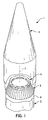
- Apparatus 1 according to the invention as depicted in Figures 1-3, comprises a rocket launch vehicle 2 including an adaptor interface fitting 3.
- a rocket payload 4 is mounted on the rocket launch vehicle 2 by way of the adaptor interface fitting 3.
- a damper 5 of the invention is located between the rocket payload and the adaptor interface fitting for damping vibrations between the rocket launch vehicle and the rocket payload.
- the rocket launch vehicle 2 has a generally cylindrical cross-section having a top end 6 and a bottom end (not shown).
- the payload adaptor fitting 3 is fixedly mounted on the top end 6 of the launch vehicle 2 in a known manner.
- the launch vehicle 2, the rocket payload 4, and the payload adaptor fitting 3 lie along a longitudinal axis 7.
- the adaptor interface fitting 3 has the shape of a cone section having opposite circular ends 8, 9.
- the circular end 8 has a larger diameter than the diameter of the other circular end 9.
- the top end 6 of the launch vehicle 2 is fixedly connected to the circular end 8 of the adaptor interface fitting 3.
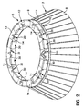
- the damper 5 lies along the longitudinal axis 7 and is operatively connected between the circular end 9 of the fitting 3 and the payload 4 as shown in Figure 3.
- the damper. 5 includes a first ring-shaped member 10 having a first platform surface 11 engaged with the circular end 9 of the fitting 3.
- the damper 5 also includes a second ring-shaped member 12 having a second platform surface 13 for engagement with the rocket payload 4.
- a series of composite structure elements 14 according to the invention are disposed between and around the periphery of the first and second ring-shaped members 10 and 12.
- the composite structure elements 14 are spaced equally apart from each other around the first and second ring-shaped members.
- the construction of each of the composite structure elements 14 is the same in the disclosed embodiment, each having an essentially block configuration with a built-in damping capacity for minimizing or eliminating the need for an actively controlled damper of the type disclosed in U.S. Patent No. 5,655,757, for example.
- the elements are held in position between the members 10 and 12 by enclosure members 30 crimped to the sides of the second ring-shaped member 12 and extending the elements 14 as shown in Fig. 2.
- Other fastening arrangements or bonding of the components could also be employed to secure the elements 14 in position.
- Each composite structure element 14 of the ring-shaped damper 5 comprises, in the form of the invention depicted in Figure 4, a non-metallic matrix 17, a plurality of filaments 18 and a lightweight metal 19 having a specific damping capability of at least 1% provided on the filaments of the composite structure element for attenuating vibrations of the element.
- the non-metallic matrix 17 is preferably a resin material, for example, an epoxy resin, which can be injection-molded or otherwise provided about the filaments 18 with lightweight metal coating 19 thereon to form the composite structure element.
- the filaments 18 of composite structure element 14 are carbon fibers in the disclosed embodiment, but filaments of other materials could be employed as noted above.
- the filaments 18 in Figure 4 extend unidirectionally in the matrix 17. Their length can be continuous along the longitudinal extent of the composite structure element.
- the filaments 18 can be in the form of a woven cloth of filaments 28 extending bidirectionally in the matrix, as illustrated in Figure 7.
- the filaments can be chopped fibers having a relatively short length and being randomly directed in the matrix, as shown at 24 with respect to the embodiment in Figure 5.
- the filaments 18 in the composite structure element 14 of Figure 4 are each coated with a lightweight metal having a specific damping capability of at least 1% for attenuating vibrations of the element.
- the lightweight metal is preferably selected from the group consisting of a magnesium alloy and an aluminum alloy. Table 1 below lists aluminum and magnesium alloys, by their ASTM designation, along with their specific damping capacity, percent at varying levels of stress, which provide the aforementioned specific damping capability of at least 1% at one or more levels of stress for attenuating vibrations of the element.
- AZ91A.B.D F 2.67 5.33 12.0 16.0 29.33 AZ31B F 1.04 1.57 2.04 2.38 2.72 Al Alloys 355 T6 ... 0.51 0.67 1.0 ... 356 T6 0.3 0.48 0.62 0.82 1.2
- the lightweight metal 19 is coated on the carbon fibers 18 of element 14 by vapor deposition or other conventional technique for wetting the fibers with molten magnesium or aluminum alloy.
- the fibers 18 are preferably coated with a thickness of metal 19 between .1 and 100 times the diameter of the carbon fibers 18.
- the coating 19 is most preferably a magnesium-zirconium alloy composed of 90-99.9 wt.% of magnesium and 10-0.1 wt.% of zirconium. These alloys have excellent damping capacity, e.g., the ability of the metal to elastically absorb vibrational energy and keep the vibrations from transmitting through the metal. Specific damping is defined as the ratio between energy lost to a maximum possible energy absorbed.
- the composite structure element 14 of the invention has a high stiffness as the most advanced structure and, at the same time, has sufficient damping capabilities for use in constructing the ring-shaped damper 5.
- the amount of damping in the structure can be controlled by a composite structure fabrication.
- the damper 5 in Figures 1-3 further comprises a plurality of load-carrying springs 20 (Figure 2) disposed between and around the first and second ring-shaped members 10, 12.
- the load springs 20 are spaced equally apart from each other around the first and second ring-shaped members 10, 12.
- the load springs 20 are disposed alternately between the series of composite structure elements 14.
- the load springs 20 together with the elements 14 act as load carrying and connecting elements between the first and second ring-shaped members 10, 12.
- the first and second ring-shaped members 10, 12 move axially and/or laterally relative to each other. This relative movement is damped by the composite structure elements 14 disposed between and around the periphery of the first and second ring-shaped members 10, 12.
- the springs 20 could be omitted or placed radially inside or outside the composite structure elements.
- a singular, continuous, annular composite structure element could be secured between the first and second ring-shaped members 10, 12 for damping vibration.
- Coated fibers as in Fig. 4 could be employed in a variation of the invention together with a porous matrix material whose pores are filled with a lightweight metal having a specific damping capability of at least 1% as shown in Fig. 5.
- the present invention further comprises a payload fairing 25, a satellite bus 26 and a satellite deployable antennae 27, shown generally in Fig. 3, constructed with one or more composite structure elements of the invention.
- the cross-section through an annular portion of the payload fairing 25, see Fig. 6, illustrates the use of continuous length filaments 31 extending unidirectionally, e.g., circumferentially about the fairing in the composite structure of the fairing.
- the payload fairing 25 preferably comprises a non-metallic matrix, a plurality of filaments 31 within the matrix reinforcing the matrix, and a lightweight metal having a specific damping capability of at least 1% coated on the filaments of the composite structure element attenuating vibrations of the element.
- a portion of the satellite bus 26 depicted in Fig. 7 shows the use of a woven cloth 28 of bidirectionally extending filaments, preferably carbon fibers, used in forming the composite structure element of the bus.
- a detail of a portion of the satellite deployable antennae 27 of Fig. 3 is shown in Fig. 8.
- a metal wire mesh 29 of the deployable antennae is embedded in a lightweight metal 32 having a specific damping capability of at least 1% in accordance with the invention for attenuating vibration of the deployable antennae.
- the mesh 29 is formed of molybdenum wire coated with gold.
- a method of the invention for making a composite structure element with built-in damping comprises the steps of providing a structural member which is subject to being disturbed when used for its intended purpose, and providing a lightweight metal having a specific damping capability of at least 1% on the structural member so as to damp disturbances of the structural member.
- a composite structure element of the invention with the highest specific damping and highest stiffness will be lightweight with properly tailored mechanical characteristics for given structural system requirements.
- a spacecraft bus and a spacecraft fairing of the invention are able to attenuate acoustic disturbances, as well as any other disturbance, during take-off.
- a slew maneuver is controllable and a settling time is shorter with the invention than with conventional spacecraft buses and fairings.
- the composite structure element of the invention can be used in different forms, e.g., tubing, triangles, pyramids, cubes for continuous damping or distributed damping of vibrations. It is not necessary to use a continuous solid piece.
- Various polymers and other matrix materials could be employed in the composite structure element. Therefore, I do not wish to be limited to the details shown and described herein, but intend to cover all such changes and modifications as are encompassed by the scope of the appended claims.
Landscapes
- Engineering & Computer Science (AREA)
- General Engineering & Computer Science (AREA)
- Mechanical Engineering (AREA)
- Remote Sensing (AREA)
- Aviation & Aerospace Engineering (AREA)
- Chemical & Material Sciences (AREA)
- Composite Materials (AREA)
- Manufacture Of Alloys Or Alloy Compounds (AREA)
- Laminated Bodies (AREA)
- Details Of Aerials (AREA)
Claims (17)
- Strukturbauteil (14) aus Verbundwerkstoff mit integrierter Dämpfung, wobei das Strukturbauteil aus Verbundwerkstoff aufweist:eine nicht metallische Matrix (15);eine Mehrzahl Filamente (18) in der Matrix (15), die die Matrix (15) verstärken; undein Leichtmetall (19) mit einer spezifischen Dämpfungsfähigkeit von mindestens 1% bei einem oder mehreren Belastungsniveaus, mit dem die Filamente (18) in der nicht metallischen Matrix (15) des Strukturbauteils (14) aus Verbundwerkstoff beschichtet sind, um Schwingungen des Bauteils (14) zu dämpfen.
- Strukturbauteil (14) aus Verbundwerkstoff nach Anspruch 1, bei dem das Leichtmetall (19) aus der Gruppe gewählt wird, die eine Magnesiumlegierung und eine Aluminiumlegierung enthält.
- Strukturbauteil (14) aus Verbundwerkstoff nach Anspruch 2, bei dem das Leichtmetall (19) eine Magnesiumlegierung ist, die 0,1 bis 10 Gew.-% Zirkon enthält und der Rest im Wesentlichen Magnesium ist.
- Strukturbauteil (14) aus Verbundwerkstoff nach einem der vorigen Ansprüche, bei dem die Matrix (15) porös ist und die Poren der Matrix (15) mit dem Leichtmetall (19) gefüllt sind.
- Strukturbauteil (14) aus Verbundwerkstoff nach Anspruch 4, bei dem die Matrix (15) ein kohlenstoffhaltiges Material ist.
- Strukturbauteil (14) aus Verbundwerkstoff nach einem der vorigen Ansprüche, bei dem die Filamente (18) Kohlenstofffasern sind.
- Strukturbauteil (14) aus Verbundwerkstoff nach einem der vorigen Ansprüche, bei dem sich die Filamente (18) einseitig gerichtet in der Matrix (15) erstrecken.
- Strukturbauteil (14) aus Verbundwerkstoff nach einem der Ansprüche 1 bis 6, bei dem die Filamente (18) eine regellos gerichtete Orientierung in der Matrix (15) haben.
- Vorrichtung aufweisend:eine Trägerrakete (2), die ein Adapterverbindungsfitting (3) enthält;eine Raketennutzlast (4), die an der Trägerrakete (2) über das Adapterverbindungsfitting (3) angebaut ist; undeinen Dämpfer (5), der zwischen der Raketennutzlast (4) und dem Adapterverbindungsfitting (3) angeordnet ist, um Schwingungen zwischen der Trägerrakete (2) und der Raketennutzlast (4) zu dämpfen;wobei der Dämpfer (5) das Strukturbauteil (14) aus Verbundwerkstoff nach einem der vorigen Ansprüche enthält.
- Vorrichtung nach Anspruch 9, bei der das Leichtmetall des Strukturbauteils (14) aus Verbundwerkstoff aus der Gruppe gewählt wird, die eine Magnesiumlegierung und eine Aluminiumlegierung enthält.
- Vorrichtung nach Anspruch 10, bei der die Matrix des Strukturbauteils (14) aus Verbundwerkstoff ein poröses kohlenstoffhaltiges Material ist, wobei die Poren der Matrix mit dem Leitmetall gefüllt sind.
- Vorrichtung aufweisend:eine Trägerrakete (2), die ein Adapterverbindungsfitting (3) enthält;eine Raketennutzlast (4), die an der Trägerrakete (2) über das Adapterverbindungsfitting (3) angebaut ist; undeine Raketenverkleidung (25), die mit der Trägerrakete (2) verbunden ist und die Raketennutzlast (4) umgibt;wobei die Raketenverkleidung (25) das Strukturbauteil (14) aus Verbundwerkstoff nach einem der Ansprüche 1 bis 8 enthält.
- Vorrichtung nach Anspruch 12, bei der die Matrix des Strukturbauteils (14) aus Verbundwerkstoff ein poröses kohlenstoffhaltiges Material ist, wobei die Poren der Matrix mit dem Leichtmetall gefüllt sind.
- Sammelschiene (26) eines Raumfahrzeugs, die das Strukturelement (14) aus Verbundwerkstoff nach einem der Ansprüche 1 bis 8 enthält.
- Strukturbauteil aus Verbundwerkstoff mit integrierter Dämpfung, wobei das Strukturbauteil aus Verbundwerkstoff aufweist:ein Metallgitter (29); undein Leichtmetall (19) mit einer spezifischen Dämpfungsfähigkeit von mindestens 1% bei einem oder mehreren Belastungsniveaus, das auf dem Metallgitter (29) aufgebracht ist, um Schwingungen des Bauteils (14) zu dämpfen.
- Strukturbauteil aus Verbundwerkstoff nach Anspruch 15, bei dem das Strukturbauteil aus Verbundwerkstoff zum Aufbau einer ausfahrbaren Satellitenantenne (27) verwendet wird, wobei das Metallgitter (29) aus mit Gold beschichtetem Molybdändraht gebildet ist und das am Gitter (29) aufgebrachte Leichtmetall aus der eine Magnesiumlegierung und eine Aluminiumlegierung enthaltenden Gruppe gewählt wird.
- Verfahren zur Bereitstellung eines Strukturbauteils aus Verbundwerkstoff mit integrierter Dämpfung, aufweisend: Bereitstellen einer nicht metallischen Matrix (15); Ausbilden einer Mehrzahl Filamente (18) in der Matrix (15), die die Matrix (15) verstärken; und Beschichten der Filamente (18) in der nicht metallischen Matrix des Strukturbauteils aus Verbundwerkstoff mit einem Leichtmetall (19) mit einer spezifischen Dämpfungsfähigkeit von mindestens 1% bei einem oder mehreren Belastungsniveaus, um Schwingungen des Bauteils zu dämpfen.
Applications Claiming Priority (2)
| Application Number | Priority Date | Filing Date | Title |
|---|---|---|---|
| US321502 | 1999-05-27 | ||
| US09/321,502 US6345788B1 (en) | 1999-05-27 | 1999-05-27 | Composite structure element with built-in damping |
Publications (3)
| Publication Number | Publication Date |
|---|---|
| EP1055600A2 EP1055600A2 (de) | 2000-11-29 |
| EP1055600A3 EP1055600A3 (de) | 2001-08-29 |
| EP1055600B1 true EP1055600B1 (de) | 2006-03-29 |
Family
ID=23250870
Family Applications (1)
| Application Number | Title | Priority Date | Filing Date |
|---|---|---|---|
| EP00110232A Expired - Lifetime EP1055600B1 (de) | 1999-05-27 | 2000-05-18 | Strukturbauteil aus einem Verbundwerkstoff mit eingebauter Dämpfung |
Country Status (4)
| Country | Link |
|---|---|
| US (1) | US6345788B1 (de) |
| EP (1) | EP1055600B1 (de) |
| JP (1) | JP3367936B2 (de) |
| DE (1) | DE60026896T2 (de) |
Families Citing this family (15)
| Publication number | Priority date | Publication date | Assignee | Title |
|---|---|---|---|---|
| FR2787764B1 (fr) * | 1998-12-29 | 2001-02-16 | Centre Nat Etd Spatiales | Dispositif de suspension d'une charge utile dans un lanceur spatial |
| SE515850C2 (sv) * | 2000-09-18 | 2001-10-15 | Saab Ericsson Space Ab | Anordning och metod vid en rymdfarkost |
| US20050064165A1 (en) * | 2003-09-22 | 2005-03-24 | Cleveland Mark A. | Acoustically damped composite construction for the forward portion of a rocket or missile |
| US7222823B2 (en) * | 2004-07-06 | 2007-05-29 | Ata Engineering, Inc. | Payload adapter |
| DE102009054458A1 (de) | 2009-12-10 | 2011-06-16 | Zf Friedrichshafen Ag | Anordnungsstruktur in Sandwichbauweise und deren Anwendung |
| RU2478532C1 (ru) * | 2011-08-04 | 2013-04-10 | Открытое акционерное общество "Ракетно-космическая корпорация "Энергия" имени С.П. Королева" | Космическая головная часть и способ ее сборки |
| RU2478531C1 (ru) * | 2011-08-04 | 2013-04-10 | Открытое акционерное общество "Ракетно-космическая корпорация "Энергия" имени С.П. Королева" | Космическая головная часть |
| ES2597706T3 (es) * | 2012-05-09 | 2017-01-20 | Ruag Space Ab | Anillo de interfaz de soporte de carga para una nave espacial |
| US20140332632A1 (en) * | 2013-05-10 | 2014-11-13 | Space Systems/Loral, Llc | Isolation of payload from launch vehicle dynamic loads |
| RU2564458C1 (ru) * | 2014-06-26 | 2015-10-10 | Российская Федерация, от имени которой выступает Федеральное космическое агентство | Космическая головная часть |
| KR101854140B1 (ko) | 2016-11-01 | 2018-05-03 | 한국항공우주연구원 | 위성 구조체 |
| US10562650B2 (en) * | 2017-06-28 | 2020-02-18 | The Boeing Company | Corrugated payload adaptor structure |
| KR102007185B1 (ko) * | 2017-12-08 | 2019-08-05 | 연세대학교 산학협력단 | 탄성메타물질을 이용한 인공위성 우주 테더 장치 |
| RU183999U1 (ru) * | 2018-04-18 | 2018-10-11 | Федеральное государственное автономное образовательное учреждение высшего образования "Национальный исследовательский Томский государственный университет" (НИ ТГУ) | Адаптер в виде конической оболочки вращения из композиционных материалов |
| CN111619831B (zh) * | 2020-04-29 | 2021-11-16 | 航天东方红卫星有限公司 | 一种连杆式星箭分离机构 |
Family Cites Families (23)
| Publication number | Priority date | Publication date | Assignee | Title |
|---|---|---|---|---|
| US4310132A (en) * | 1978-02-16 | 1982-01-12 | Nasa | Fuselage structure using advanced technology fiber reinforced composites |
| US4411380A (en) * | 1981-06-30 | 1983-10-25 | The United States Of America As Represented By The Administrator Of The National Aeronautics And Space Administration | Metal matrix composite structural panel construction |
| US4682744A (en) * | 1985-04-08 | 1987-07-28 | Rca Corporation | Spacecraft structure |
| JPS6360743A (ja) * | 1986-09-02 | 1988-03-16 | 東レ株式会社 | 軽量複合材料 |
| US4898783A (en) * | 1986-10-14 | 1990-02-06 | The Dow Chemical Company | Sound and thermal insulation |
| US4812854A (en) * | 1987-05-05 | 1989-03-14 | Harris Corp. | Mesh-configured rf antenna formed of knit graphite fibers |
| US4983451A (en) | 1987-08-05 | 1991-01-08 | Kabushiki Kaisha Kobe Seiko Sho | Carbon fiber-reinforced carbon composite material and process for producing the same |
| CA1332129C (en) * | 1987-11-21 | 1994-09-27 | Tadao Inabata | Light filler material having damping function and composite material thereof |
| DD278990A1 (de) * | 1988-12-30 | 1990-05-23 | Oschatz Glasseide Veb | Leitfaehiges textiles flaechengebilde aus glasseidenelementarfaeden |
| US5171630A (en) * | 1989-04-17 | 1992-12-15 | Georgia Tech Research Corporation | Flexible multiply towpreg |
| FR2655036B1 (fr) * | 1989-11-27 | 1993-07-09 | Pradom Ltd | Materiaux composites complexes a matrice organique-metallique, leur procede de fabrication et leur utilisation pour la fabrication de produits de haute technologie destines notamment a l'aerospatial ou aux vehicules a grande vitesse, tels que tgv. |
| CA2042417A1 (en) * | 1990-05-29 | 1991-11-30 | Peter G. Donecker | Process to manufacture conductive composite articles |
| FR2667616B1 (fr) * | 1990-10-05 | 1993-01-15 | Aerospatiale | Procede et installation de metallisation en continu d'une meche de fibres etalee. |
| US5494634A (en) * | 1993-01-15 | 1996-02-27 | The United States Of America As Represented By The Secretary Of The Navy | Modified carbon for improved corrosion resistance |
| US5474262A (en) * | 1994-02-08 | 1995-12-12 | Fairchild Space And Defense Corporation | Spacecraft structure and method |
| GB9408567D0 (en) * | 1994-04-29 | 1994-06-22 | Mediquest Products Ltd | A valve for urine drainage applications |
| US5655757A (en) | 1995-02-17 | 1997-08-12 | Trw Inc. | Actively controlled damper |
| GB9504372D0 (en) * | 1995-03-04 | 1995-04-26 | British Aerospace | A composite laminate |
| US6045680A (en) * | 1996-05-30 | 2000-04-04 | E. I. Du Pont De Nemours And Company | Process for making thermally stable metal coated polymeric monofilament or yarn |
| US5848767A (en) * | 1996-08-05 | 1998-12-15 | The Boeing Company | One piece spacecraft frame |
| AU5584898A (en) * | 1996-11-15 | 1998-06-03 | Brigham Young University | Damped composite structures with fiber wave patterns and method and apparatus for making same |
| US5961078A (en) * | 1997-06-27 | 1999-10-05 | Mcdonnell Douglas Corporation | Passive axial vibration isolation system for a spacecraft launch vehicle |
| US6098926A (en) * | 1998-08-06 | 2000-08-08 | Lockheed Martin Corporation | Composite fairing with integral damping and internal helmholz resonators |
-
1999
- 1999-05-27 US US09/321,502 patent/US6345788B1/en not_active Expired - Lifetime
-
2000
- 2000-05-18 DE DE60026896T patent/DE60026896T2/de not_active Expired - Lifetime
- 2000-05-18 EP EP00110232A patent/EP1055600B1/de not_active Expired - Lifetime
- 2000-05-26 JP JP2000156164A patent/JP3367936B2/ja not_active Expired - Fee Related
Also Published As
| Publication number | Publication date |
|---|---|
| JP3367936B2 (ja) | 2003-01-20 |
| EP1055600A3 (de) | 2001-08-29 |
| JP2001129917A (ja) | 2001-05-15 |
| US6345788B1 (en) | 2002-02-12 |
| DE60026896D1 (de) | 2006-05-18 |
| DE60026896T2 (de) | 2006-08-24 |
| EP1055600A2 (de) | 2000-11-29 |
Similar Documents
| Publication | Publication Date | Title |
|---|---|---|
| EP1055600B1 (de) | Strukturbauteil aus einem Verbundwerkstoff mit eingebauter Dämpfung | |
| CA1274500A (en) | Spacecraft structure | |
| US9823143B2 (en) | Additively grown enhanced impact resistance features for improved structure and joint protection | |
| EP2496906B1 (de) | Verbesserungen im bezug auf eine panzerung | |
| US20080136071A1 (en) | Elastomeric isolator | |
| US5419416A (en) | Energy absorber having a fiber-reinforced composite structure | |
| US5961078A (en) | Passive axial vibration isolation system for a spacecraft launch vehicle | |
| EP0145182A1 (de) | Schwungrad zum Speichern von Energie | |
| US6012680A (en) | Passive lateral vibration isolation system for a spacecraft launch vehicle | |
| JP2003291232A (ja) | 繊維強化プラスチックからなる構造体 | |
| US4954377A (en) | Load bearing connective damper | |
| US20070235274A1 (en) | Composite helmet for body mount | |
| US9140278B2 (en) | Anti-rotation isolator | |
| US7222823B2 (en) | Payload adapter | |
| US20150330567A1 (en) | Component comprising a metal matrix reinforcement member and method of formation thereof | |
| RU197021U1 (ru) | Силовая конструкция корпуса космического аппарата | |
| US20230211901A1 (en) | Latticed structure for vibration control in dynamic environments | |
| EP4006364A1 (de) | Strukturelle sicherung | |
| GB2390999A (en) | Composite material for acoustic or mechanical damping | |
| US10562650B2 (en) | Corrugated payload adaptor structure | |
| EP4180688A1 (de) | Schwingungsdämpfungsvorrichtung zur dämpfung der schwingungen zwischen zwei mechanischen teilen | |
| RU2000113596A (ru) | Композиционный структурный элемент со встроенным демпфером (варианты), устройство с композиционным структурным элементом (варианты) и способ получения композиционного структурного элемента | |
| CN117759679A (zh) | 一种用于载人航天器控制力矩陀螺的隔振降噪系统 | |
| US20040072938A1 (en) | Passive damping with platelet reinforced viscoelastic materials |
Legal Events
| Date | Code | Title | Description |
|---|---|---|---|
| PUAI | Public reference made under article 153(3) epc to a published international application that has entered the european phase |
Free format text: ORIGINAL CODE: 0009012 |
|
| AK | Designated contracting states |
Kind code of ref document: A2 Designated state(s): AT BE CH CY DE DK ES FI FR GB GR IE IT LI LU MC NL PT SE Kind code of ref document: A2 Designated state(s): DE FR GB IT |
|
| AX | Request for extension of the european patent |
Free format text: AL;LT;LV;MK;RO;SI |
|
| PUAL | Search report despatched |
Free format text: ORIGINAL CODE: 0009013 |
|
| AK | Designated contracting states |
Kind code of ref document: A3 Designated state(s): AT BE CH CY DE DK ES FI FR GB GR IE IT LI LU MC NL PT SE |
|
| AX | Request for extension of the european patent |
Free format text: AL;LT;LV;MK;RO;SI |
|
| 17P | Request for examination filed |
Effective date: 20020128 |
|
| AKX | Designation fees paid |
Free format text: DE FR GB IT |
|
| RAP1 | Party data changed (applicant data changed or rights of an application transferred) |
Owner name: NORTHROP GRUMMAN CORPORATION |
|
| RAP1 | Party data changed (applicant data changed or rights of an application transferred) |
Owner name: NORTHROP GRUMMAN CORPORATION |
|
| 17Q | First examination report despatched |
Effective date: 20050428 |
|
| GRAP | Despatch of communication of intention to grant a patent |
Free format text: ORIGINAL CODE: EPIDOSNIGR1 |
|
| GRAS | Grant fee paid |
Free format text: ORIGINAL CODE: EPIDOSNIGR3 |
|
| GRAA | (expected) grant |
Free format text: ORIGINAL CODE: 0009210 |
|
| AK | Designated contracting states |
Kind code of ref document: B1 Designated state(s): DE FR GB IT |
|
| REG | Reference to a national code |
Ref country code: GB Ref legal event code: FG4D |
|
| PGFP | Annual fee paid to national office [announced via postgrant information from national office to epo] |
Ref country code: FR Payment date: 20060517 Year of fee payment: 7 |
|
| REF | Corresponds to: |
Ref document number: 60026896 Country of ref document: DE Date of ref document: 20060518 Kind code of ref document: P |
|
| PGFP | Annual fee paid to national office [announced via postgrant information from national office to epo] |
Ref country code: GB Payment date: 20060525 Year of fee payment: 7 |
|
| ET | Fr: translation filed | ||
| PLBE | No opposition filed within time limit |
Free format text: ORIGINAL CODE: 0009261 |
|
| STAA | Information on the status of an ep patent application or granted ep patent |
Free format text: STATUS: NO OPPOSITION FILED WITHIN TIME LIMIT |
|
| 26N | No opposition filed |
Effective date: 20070102 |
|
| GBPC | Gb: european patent ceased through non-payment of renewal fee |
Effective date: 20070518 |
|
| REG | Reference to a national code |
Ref country code: FR Ref legal event code: ST Effective date: 20080131 |
|
| PG25 | Lapsed in a contracting state [announced via postgrant information from national office to epo] |
Ref country code: GB Free format text: LAPSE BECAUSE OF NON-PAYMENT OF DUE FEES Effective date: 20070518 |
|
| PG25 | Lapsed in a contracting state [announced via postgrant information from national office to epo] |
Ref country code: FR Free format text: LAPSE BECAUSE OF NON-PAYMENT OF DUE FEES Effective date: 20070531 |
|
| PGFP | Annual fee paid to national office [announced via postgrant information from national office to epo] |
Ref country code: IT Payment date: 20080523 Year of fee payment: 9 |
|
| PG25 | Lapsed in a contracting state [announced via postgrant information from national office to epo] |
Ref country code: IT Free format text: LAPSE BECAUSE OF NON-PAYMENT OF DUE FEES Effective date: 20090518 |
|
| PGFP | Annual fee paid to national office [announced via postgrant information from national office to epo] |
Ref country code: DE Payment date: 20110520 Year of fee payment: 12 |
|
| REG | Reference to a national code |
Ref country code: DE Ref legal event code: R082 Ref document number: 60026896 Country of ref document: DE Representative=s name: WUESTHOFF & WUESTHOFF PATENT- UND RECHTSANWAEL, DE |
|
| REG | Reference to a national code |
Ref country code: DE Ref legal event code: R081 Ref document number: 60026896 Country of ref document: DE Owner name: NORTHROP GRUMMAN SYSTEMS CORPORATION, US Free format text: FORMER OWNER: NORTHROP GRUMMAN CORP., LOS ANGELES, US Effective date: 20120814 Ref country code: DE Ref legal event code: R082 Ref document number: 60026896 Country of ref document: DE Representative=s name: WUESTHOFF & WUESTHOFF PATENT- UND RECHTSANWAEL, DE Effective date: 20120814 Ref country code: DE Ref legal event code: R081 Ref document number: 60026896 Country of ref document: DE Owner name: NORTHROP GRUMMAN SYSTEMS CORPORATION, LOS ANGE, US Free format text: FORMER OWNER: NORTHROP GRUMMAN CORP., LOS ANGELES, CALIF., US Effective date: 20120814 Ref country code: DE Ref legal event code: R082 Ref document number: 60026896 Country of ref document: DE Representative=s name: WUESTHOFF & WUESTHOFF, PATENTANWAELTE PARTG MB, DE Effective date: 20120814 |
|
| REG | Reference to a national code |
Ref country code: DE Ref legal event code: R119 Ref document number: 60026896 Country of ref document: DE Effective date: 20121201 |
|
| PG25 | Lapsed in a contracting state [announced via postgrant information from national office to epo] |
Ref country code: DE Free format text: LAPSE BECAUSE OF NON-PAYMENT OF DUE FEES Effective date: 20121201 |