EP1055553A2 - Active head rest for automotive vehicle seats - Google Patents
Active head rest for automotive vehicle seats Download PDFInfo
- Publication number
- EP1055553A2 EP1055553A2 EP00109841A EP00109841A EP1055553A2 EP 1055553 A2 EP1055553 A2 EP 1055553A2 EP 00109841 A EP00109841 A EP 00109841A EP 00109841 A EP00109841 A EP 00109841A EP 1055553 A2 EP1055553 A2 EP 1055553A2
- Authority
- EP
- European Patent Office
- Prior art keywords
- headrest
- locking
- sensor
- mechanical
- backrest
- Prior art date
- Legal status (The legal status is an assumption and is not a legal conclusion. Google has not performed a legal analysis and makes no representation as to the accuracy of the status listed.)
- Withdrawn
Links
Images


Classifications
-
- B—PERFORMING OPERATIONS; TRANSPORTING
- B60—VEHICLES IN GENERAL
- B60N—SEATS SPECIALLY ADAPTED FOR VEHICLES; VEHICLE PASSENGER ACCOMMODATION NOT OTHERWISE PROVIDED FOR
- B60N2/00—Seats specially adapted for vehicles; Arrangement or mounting of seats in vehicles
- B60N2/80—Head-rests
- B60N2/806—Head-rests movable or adjustable
- B60N2/838—Tiltable
- B60N2/853—Tiltable characterised by their adjusting mechanisms, e.g. electric motors
-
- B—PERFORMING OPERATIONS; TRANSPORTING
- B60—VEHICLES IN GENERAL
- B60N—SEATS SPECIALLY ADAPTED FOR VEHICLES; VEHICLE PASSENGER ACCOMMODATION NOT OTHERWISE PROVIDED FOR
- B60N2/00—Seats specially adapted for vehicles; Arrangement or mounting of seats in vehicles
- B60N2/80—Head-rests
- B60N2/806—Head-rests movable or adjustable
- B60N2/809—Head-rests movable or adjustable vertically slidable
Definitions
- the invention relates to an active headrest for motor vehicle seats, with a device that causes a rear impact on the vehicle and a mechanism coupled with this device and the headrest, by means of the headrest integrated in the backrest after the rear impact is shiftable in the front.
- a headrest which is usually both in height and in terms of their inclination, i.e. regarding the distance to the head of the Vehicle occupants are adjustable.
- these headrests are often fake set or the setting that changes operationally is not with corrected enough attention. The consequence of this is a extensive loss of the safety function of the headrest with the danger whiplash due to the whip effect, i.e. of Throwing the head back in the event of an impact by a subsequent one Vehicle to the rear.
- the basis of the system is a mechanism by means of which the headrest is over a lever with a pressure absorbing device inside the Backrest is connected. Accelerated from behind in the event of an impact the vehicle and seat in the forward direction, which leads to the Vehicle occupants are pressed into the seat. This will be a big part the backrest is pushed in by the weight of the occupants' bodies. This force exerted by the body during a rear impact activates the Pressure absorption device that is pushed backwards and over the Lever a combined up / forward movement of the on a lever arm attached headrest causes.
- Moving the headrest forward reduces the distance to the Head of the respective vehicle occupant.
- the heads of vehicle occupants can intercepted earlier when struck back by a rear impact and the Stress on the cervical spine and thus the effects of one Whiplash injuries can be reduced.
- the Saab 9 - 5 model has a comparable one mechanical system for active adjustment of the headrest in one Rear impact on.
- the invention has for its object the active described above Headrest for motor vehicle seats, with a device that one Rear impact on the vehicle is detected and one with this device and the Mechanism coupled to the headrest, by means of which in the backrest integrated headrest in the rear impact can be moved forward, so train that the trigger conditions are adjustable and not from Weight or depending on the seating position of the vehicle occupants.
- the Headrest rotates around a horizontal axis in the frame of the Backrest of the seat is integrated and one with the headrest in the Active spring arrangement in connection with a detachable mechanical locking is provided, such that the headrest in normal operating condition spring loaded against movement after is locked at the front that a releasable mechanical locking arrangement for Lock the headrest against backward movement and that one Sensor-controlled trigger system is provided, which on the one hand with a Rear impact sensing sensor is connected and on the other hand with the Locking is in active engagement, such that when the sensor responds the lock can be released.
- a particularly simple and effective locking can be according to a development of the invention achieve if an articulated with each other as locking Double lever system is provided, of which a lever is formed with one arm and is coupled to the headrest and of which the other lever has two arms trained, rotatably mounted and spring-loaded, and with the free lever arm is detachably mechanically locked in the release system.
- Electromagnetic actuator which is an electrical one Signal emitting sensor is connected and its active element with the Lock is coupled.
- the mechanical sensor is preferably by one in the Backrest integrated pressure plate formed.
- the detachable, i.e. reversible mechanical lock to prevent a Swiveling the headrest backwards is according to an advantageous Embodiment of the invention preferably by using the headrest coupled tooth segment in connection with a vehicle-mounted Lock pin or a corresponding pawl is formed. This is with simple means a safe reversible lock is guaranteed.
- Headrests typically have two adjustment tubes, which are in bearing sleeves are guided.
- the construction is preferably according to a further development of Invention made such that the bearing sleeves an integral part of a rectangular rocker are rotatable in the frame of a shaft Backrest is held and at which the coupling points for locking and the lock are formed.
- This construction can be relatively simple Be realized and allows a safe mode of operation that the usual security standards are sufficient.
- a headrest 1 which is padded in the usual way has two adjusting tubes 2 on, which are each slidably guided in a bearing sleeve 3.
- Clamping rings 4 in conjunction with slotted upper ends of the bearing sleeves ensure in conventional way for a frictional seat of the adjustment tubes 2.
- Both adjustment tubes 2 are an integral part of a rectangular shape Rocker 5, which is for radiating weight and strength reasons is structured.
- On the rear side of the rocker 5 are bearings 6 for above a shaft 7 attached, with its two ends in brackets 8 on Frame 9 of the backrest of a motor vehicle seat is rotatably held is.
- the headrest 1 is therefore around the axis predetermined by this shaft 7 with their adjustment tubes 2 and the associated rocker 5 around a horizontal Axis rotatably integrated in frame 9 of the backrest.
- a torsion spring 10 sits coaxially at both ends each with its one end 10 a on an extension 5 a of the rocker 5 and with its other end 10 b on a firmly connected to the frame 9 Housing 11 is spring-loaded.
- the direction of rotation of the torsion spring is included so that the preload tries to turn the headrest 1 forward.
- the headrest 1 is in the normal operating state spring biased locked for movement forward.
- the lock first includes an adjusting lever 12 which has one end in one Bearing extension 5 b articulated on the lower web of the rocker 5 and the other end is rotatably connected to a release lever 13.
- the Release lever 13 is rotatable about an axis 13 a on the housing 11, biased by a tension wire 14, articulated. The preload through the tensioning wire 14 is directed so that when the Release lever 13 rotated this clockwise.
- the housing 11 has a lower extension 11 a, on which a trigger magnet 15 with a movable, metallic pin 15 a, which retracts when the trigger magnet is activated is, and a locking head 15 b, fixedly attached by means of a bracket 16 is.
- a trigger magnet 15 with a movable, metallic pin 15 a which retracts when the trigger magnet is activated is
- a locking head 15 b fixedly attached by means of a bracket 16 is.
- Fig. 5 A is the lower arm of the Release lever 13 locked in the locking head 15 b by means of the pin 15 a.
- a tooth segment extension 17 on the rocker 5 in connection with a Lock pin 18 which is slidably mounted in the housing 11 is formed.
- a Lock pin 18 which is slidably mounted in the housing 11 is formed.
- Fig. 5 A in the normal operating state (Fig. 5 A), limited by the stop 19, snaps the locking pin 18 in the leftmost tooth space.
- Fig. 5 B At a Pivotal movement of the headrest 1 after release of the release lever 13 (Fig. 5 B) "ratchets" the tooth segment over the locking pin until the rocker is on the housing wall of the housing 11, which serves as a limitation, strikes. Both in this position and in all intermediate positions the headrest 1 is locked against swiveling backwards, because immediately the locking pin would snap into the next tooth gap.
- the headrest is appropriately provided with a damper, which dampens the forward movement of the headrest after it has been triggered or decelerates while reducing the impact speed of the rocker 5 to the stop 11.
- the damper can be made from an elastically deformable Material, e.g. PU foam, a rubber element, an air cushion, or similar structures exist.
- the arrangement of a compression spring 20 on Stop 11 according to FIG. 5 A is conceivable.
- the headrest according to the invention works as follows:
- the sensor can be activated by a sensor that responds to accelerations are formed, which, similar to the deployment of an airbag, at a certain acceleration value gives an electrical signal, which the electromagnetic release system, the crash magnet 15, and activated Release lever releases.
- the sensor can also be a pressure sensor integrated in the vehicle seat, an electrical pulse when a predetermined force is exerted on it emits, which activates the trigger magnet 15.
- a mechanical sensor can also be used be provided, for example, by an integrated in the vehicle seat flat pressure plate is formed, the lever, ropes, trains or the same with the locking of the release lever in releasable operative engagement stands.
- torsion springs 10 instead of the two torsion springs 10, a single one can also be on the shaft 7 continuous torsion spring can be used.
- Other types of springs for example, torsion springs, torsion bar springs or the like applicable.
Abstract
Derartige Kopfstützen weisen typischerweise eine Vorrichtung auf, die einen Heckaufprall erfaßt, in Verbindung mit einer Mechanik, die die Kopfstütze bei dem Heckaufprall selbsttätig nach vorne verlagen. Um insbesondere die Auslösung der Mechanik unabhängig von Körpergröße, Gewicht und Sitzposition des Fahrzeuginsassen zu machen, ist die Kopfstütze (1) drehbeweglich im Rückenlehnen-Gestell (9) integriert und wird mittels einer Feder (10) vorgespannt, in Verbindung mit einer Arretierung (12, 13, 14, 15 a, b), die die Kopfstütze im vorgespannten Zustand hält. Mit der Arretierung ist ein Auslöser (15) gekoppelt, der mit einem den Heckaufprall verbundenen Sensor verbunden ist, der bei Aktivierung die Arretierung löst, so daß die vorgespannte Feder (10) die Kopfstütze (1) nach vorne, dem Kopf des Insassen entgegen, verschwenkt. Eine lösbare mechanische Verriegelung (17, 18) verhindert ein Zurückfedern der Kopfstütze (1). <IMAGE>Such headrests typically have a device that detects a rear impact, in conjunction with a mechanism that automatically moved the headrest forward in the rear impact. In order to make the triggering of the mechanics independent of the body size, weight and seating position of the vehicle occupant, the headrest (1) is integrated in the backrest frame (9) so that it can rotate and is pretensioned by means of a spring (10) in conjunction with a locking device (12 , 13, 14, 15 a, b), which holds the headrest in the prestressed state. A trigger (15) is coupled to the locking device and is connected to a sensor connected to the rear impact, which releases the locking device when activated, so that the prestressed spring (10) moves the headrest (1) forward, towards the occupant's head, panned. A releasable mechanical lock (17, 18) prevents the headrest (1) from springing back. <IMAGE>
Description
Die Erfindung bezieht sich auf eine aktive Kopfstütze für Kraftfahrzeug-Sitze, mit einer Vorrichtung, die einen Heckaufprall auf das Fahrzeug erläßt und einer mit dieser Vorrichtung und der Kopfstüze gekoppelten Mechanik, mittels der die in die Rückenlehne integrierte Kopfstütze bei dem Heckaufprall nach vorne verlagerbar ist.The invention relates to an active headrest for motor vehicle seats, with a device that causes a rear impact on the vehicle and a mechanism coupled with this device and the headrest, by means of the headrest integrated in the backrest after the rear impact is shiftable in the front.
Zum Schutz der Insassen von Fahrzeugen gegen den sogenannten "Peitschenschlag-Effekt" bei einem Heckaufprall sind die Fahrzeugsitze mit einer Kopfstütze versehen, die in der Regel sowohl in ihrer Höhe als auch hinsichtlich ihrer Neigung, d.h. hinsichtlich des Abstandes zu dem Kopf des Fahrzeuginsassen, verstellbar sind. Häufig sind jedoch diese Kopfstützen fälsch eingestellt bzw. die Einstellung, die sich betrieblich verändert, wird nicht mit der genügenden Aufmerksamkeit korrigiert. Die Folge davon ist ein weitgehender Verlust der Sicherheitsfunktion der Kopfstütze mit der Gefahr eines Schleudertraumas aufgrund des Peitschenschlag-Effektes, d.h. des Zurückschleuderns des Kopfes bei einem Aufprall eines nachfolgenden Fahrzeuges auf das Heck.To protect the occupants of vehicles against the so-called The "vehicle whip effect" in the event of a rear-end collision is included a headrest, which is usually both in height and in terms of their inclination, i.e. regarding the distance to the head of the Vehicle occupants are adjustable. However, these headrests are often fake set or the setting that changes operationally is not with corrected enough attention. The consequence of this is a extensive loss of the safety function of the headrest with the danger whiplash due to the whip effect, i.e. of Throwing the head back in the event of an impact by a subsequent one Vehicle to the rear.
Um diese Nachteile zu vermeiden, ist es bekannt (Automobil-Entwicklung, März 1999, Seite 12), die Vordersitze eines Personenkraftwagens mit einer aktiven Kopfstütze zu versehen, die bei einer Heck-Kollision den Peitschenschlag-Effekt und damit die Gefahr eines Schleudertraumas verringert. To avoid these disadvantages, it is known (automotive development, March 1999, page 12), the front seats of a passenger car with a to provide active head restraint, which in the event of a rear-end collision Whip effect and thus the risk of whiplash decreased.
Grundlage des Systems ist eine Mechanik, mittels derer die Kopfstütze über einen Hebel mit einer Druckaufnahme-Vorrichtung im Inneren der Rückenlehne verbunden ist. Im Fall eines Aufpralles von hinten beschleunigt das Fahrzeug samt Sitz in Vorwärtsrichtung, was dazu führt, daß die Fahrzeuginsassen in den Sitz gedrückt werden. Dadurch wird ein großer Teil der Rückenlehne durch das Gewicht der Körper der Insassen eingedrückt. Diese Krafteinwirkung der Körper beim Heck-Aufprall aktiviert dabei die Druckaufnahme-Vorrichtung, die nach hinten gedrückt wird, und über den Hebel eine kombinierte Auf-/Vorwärtsbewegung der an einem Hebelarm befestigten Kopfstütze bewirkt.The basis of the system is a mechanism by means of which the headrest is over a lever with a pressure absorbing device inside the Backrest is connected. Accelerated from behind in the event of an impact the vehicle and seat in the forward direction, which leads to the Vehicle occupants are pressed into the seat. This will be a big part the backrest is pushed in by the weight of the occupants' bodies. This force exerted by the body during a rear impact activates the Pressure absorption device that is pushed backwards and over the Lever a combined up / forward movement of the on a lever arm attached headrest causes.
Durch das Nachvorneschieben der Kopfstütze verringert sich der Abstand zum Kopf des jeweiligen Fahrzeuginsassen. Die Köpfe der Fahrzeuginsassen können so beim Zurückschlagen durch einen Heckaufprall früher abgefängen und die Belastung der Halswirbelsäulen und damit die Auswirkungen eines Schleudertraumas dadurch reduziert werden.Moving the headrest forward reduces the distance to the Head of the respective vehicle occupant. The heads of vehicle occupants can intercepted earlier when struck back by a rear impact and the Stress on the cervical spine and thus the effects of one Whiplash injuries can be reduced.
Neben dem Model "Opel Vectra", bei dem die vorgenannte aktive Kopfstütze vorgesehen ist, weist auch das Modell Saab 9 - 5 ein vergleichbares mechanisches System zur aktiven Verstellung der Kopfstütze bei einem Heckaufprall auf.In addition to the model "Opel Vectra", in which the aforementioned active headrest the Saab 9 - 5 model has a comparable one mechanical system for active adjustment of the headrest in one Rear impact on.
Trotz des Fortschrittes, die diese Systeme mit sich bringen, weisen sie noch eine Reihe von Nachteilen auf:
- Die Auslösegeschwindigkeit sowie der Auslöse- und Verfährweg der Kopfstütze ist durch die Auslegung des Hebelsystems fest vorgegeben und nicht einstellbar Dadurch ist u.a. für jeden PKW-Typ eine andere Auslegung des mechanischen Systems notwendig.
- Die Auslösung ist von der Aufprallgeschwindigkeit und von dem Gewicht des jeweiligen Insassen abhängig. Daher sind insbesondere bei kleinen Aufprallgeschwindigkeiten leichtere Personen gefährdeter als schwerere Insassen.
- Die Funktion des mechanischen Hebelsystems ist abhängig von der Sitzposition des jeweiligen Insassen. Kleine Insassen bzw. solche, die typbedingt während der Fahrt relativ weit entfernt von der Rückenlehne sitzen, sind daher gefährdeter als große Insassen, die angelehnt an der Rückenlehne sitzen.
- Die Kopfstütze ist nicht gegen Zurückfedern gesichert.
- The release speed as well as the release and travel distance of the headrest is fixed by the design of the lever system and cannot be adjusted. This means that a different design of the mechanical system is necessary for each type of car.
- The release depends on the speed of impact and the weight of the occupant. Therefore, lighter people are more at risk than heavier occupants, especially at low impact speeds.
- The function of the mechanical lever system depends on the seating position of the occupant. Small occupants or those who sit relatively far away from the backrest due to their type are therefore more at risk than large occupants who are leaning against the backrest.
- The headrest is not secured against springing back.
Der Erfindung liegt die Aufgabe zugrunde, die eingangs bezeichnete aktive Kopfstütze für Kraftfährzeug-Sitze, mit einer Vorrichtung, die einen Heckaufprall auf das Fahrzeug erfaßt und einer mit dieser Vorrichtung und der Kopfstütze gekoppelten Mechanik, mittels der die in die Rückenlehne integrierte Kopfstütze bei dem Heckaufprall nach vorne verlagerbar ist, so auszubilden, daß die Auslösebedingungen einstellbar sind und nicht vom Gewicht oder von der Sitzposition der Fahrzeuginsassen abhängig sind.The invention has for its object the active described above Headrest for motor vehicle seats, with a device that one Rear impact on the vehicle is detected and one with this device and the Mechanism coupled to the headrest, by means of which in the backrest integrated headrest in the rear impact can be moved forward, so train that the trigger conditions are adjustable and not from Weight or depending on the seating position of the vehicle occupants.
Die Lösung dieser Aufgabe gelingt gemäß der Erfindung dadurch, daß die Kopfstütze drehbeweglich um eine horizontale Achse im Gestell der Rückenlehne des Sitzes integriert ist und eine mit der Kopfstütze im Wirkeingriff stehende Federanordnung in Verbindung mit einer lösbaren mechanischen Arretierung vorgesehen ist, derart, daß die Kopfstütze im normalen betrieblichen Zustand federvorbelastet gegen eine Bewegung nach vorne arretiert ist, daß eine lösbare mechanische Verriegelungsanordnung zum Verriegeln der Kopfstütze gegen eine Bewegung nach hinten und daß ein sensorgesteuertes Auslösesystem vorgesehen ist, das einerseits mit einem den Heckaufprall erfassenden Sensor verbunden ist und andererseits mit der Arretierung im Wirkeingriff steht, derart, daß beim Ansprechen des Sensors die Arretierung lösbar ist.This object is achieved according to the invention in that the Headrest rotates around a horizontal axis in the frame of the Backrest of the seat is integrated and one with the headrest in the Active spring arrangement in connection with a detachable mechanical locking is provided, such that the headrest in normal operating condition spring loaded against movement after is locked at the front that a releasable mechanical locking arrangement for Lock the headrest against backward movement and that one Sensor-controlled trigger system is provided, which on the one hand with a Rear impact sensing sensor is connected and on the other hand with the Locking is in active engagement, such that when the sensor responds the lock can be released.
Die erfindungsgemäße aktive Kopfstütze weist eine Reihe von Vorteilen auf:
- Durch die Auslegung der Federanordnung ist die Auslösegeschwindigkeit flexibel und kann eingerichtet werden.
- Der Auslöse- und Verfahrweg ist durch eine entsprechende konstruktive Gestaltung variabel und von der Konstruktion her festlegbar
- Die Auslösung ist nicht von Aufprallgeschwindigkeit oder vom Gewicht des Insassen abhängig.
- Die Funktion der Aktivierung ist unabhängig von Sitzposition der Inassen.
- Die Kopfstütze wird durch die Verriegelung automatisch gegen Zurückfedern gesichert, und zwar sowohl in der Endposition als auch in beliebig stufigen Zwischenpositionen.
- Die Aktivierung kann mit anderen Sicherheitsbauteilen (Airbag, Gurtstraffer,...) gekoppelt werden, weil dort ebenfalls auf Beschleunigungen ansprechende Sensoren eingesetzt werden.
- Die Vorwärtsbewegung der Kopfstütze kann gedämpft werden.
- The design of the spring arrangement means that the release speed is flexible and can be set up.
- The release and travel path is variable due to a corresponding constructive design and the construction can be determined
- Deployment does not depend on the speed of impact or the weight of the occupant.
- The activation function is independent of the seating position of the occupants.
- The headrest is automatically secured against springback by the lock, both in the end position and in any intermediate position.
- Activation can be coupled with other safety components (airbag, belt tensioner, ...) because sensors that respond to acceleration are also used there.
- The forward movement of the headrest can be dampened.
Für die Ausbildung der Arretierung stehen dem Fachmann eine Reihe von konstruktiven Möglichkeiten zur Verfügung. Eine besonders einfache und wirksame Arretierung läßt sich gemäß einer Weiterbildung der Erfindung erzielen, wenn als Arretierung ein gelenkig miteinander verbundenes Doppelhebelsystem vorgesehen ist, von dem ein Hebel einarmig ausgebildet und mit der Kopfstütze gekoppelt ist und von dem der andere Hebel zweiarmig ausgebildet, drehbeweglich gelagert und federvorgespannt ist, und mit dem freien Hebelarm im Auslösesystem lösbar mechanisch arretiert ist.A number of are available to the person skilled in the art for the formation of the lock constructive options available. A particularly simple and effective locking can be according to a development of the invention achieve if an articulated with each other as locking Double lever system is provided, of which a lever is formed with one arm and is coupled to the headrest and of which the other lever has two arms trained, rotatably mounted and spring-loaded, and with the free lever arm is detachably mechanically locked in the release system.
Auch für das sensorgesteuerte Auslösesystem sind eine Reihe von Ausbildungen denkbar. Eine bevorzugte, weil mit konventionellen Komponenten realisierbare Ausbildung ist gemäß einer Ausgestaltung der Erfindung erzielbar, wenn als sensorgesteuertes Auslösesystem ein elektromagnetischer Aktuator vorgesehen ist, der mit einem ein elektrisches Signal abgebenden Sensor verbunden ist und dessen Wirkglied mit der Arretierung gekoppelt ist.There are also a number of for the sensor-controlled release system Training possible. A preferred one because with conventional Components realizable training is according to an embodiment of the Invention achievable when a sensor-controlled trigger system Electromagnetic actuator is provided, which is an electrical one Signal emitting sensor is connected and its active element with the Lock is coupled.
Es ist auch eine Ausbildung gemäß einer anderen Ausgestaltung der Erfindung denkbar, bei der ein mechanischer Sensor vorgesehen ist, der über mechanische Verbindungsglieder wie Hebel, Seile, Züge mit einem mechanischen Auslösesystem für die Arretierung gekoppelt ist.It is also an embodiment according to another embodiment of the invention conceivable, in which a mechanical sensor is provided which via mechanical links such as levers, ropes, cables with one mechanical release system for the lock is coupled.
Dabei wird der mechanische Sensor vorzugsweise durch eine in der Rückenlehne integrierte Druckplatte gebildet.The mechanical sensor is preferably by one in the Backrest integrated pressure plate formed.
Für die Vorspannung der Kopfstütze stehen dem Fachmann eine Reihe von konstruktiven Möglichkeiten zur Verfügung. Eine besonders vorteilhafte, weil konstruktiv einfache und dennoch wirksame, Lösung läßt sich gemäß einer Weiterbildung der Erfindung erzielen, wenn die Federanordnung zur Vorspannung der Kopfstütze im normalen betrieblichen Zustand durch mindestens eine Drehfeder gebildet ist, die auf einer Welle, die die horizontale Schwenkachse für die Kopfstütze vorgibt, gehalten ist.A number of are available to the person skilled in the art for prestressing the headrest constructive options available. A particularly beneficial because structurally simple, yet effective, solution can be according to one Further development of the invention achieve if the spring arrangement for Preload the headrest in normal operating condition at least one torsion spring is formed on a shaft that is horizontal Pivots for the headrest, is held.
Die lösbare, d.h. reversierbar mechanische Verriegelung zum Verhindern eines Verschwenkens der Kopfstütze nach hinten wird gemäß einer vorteilhaften Ausgestaltung der Erfindung vorzugsweise durch ein mit der Kopfstütze gekoppeltes Zahnsegment in Verbindung mit einem fahrzeugfest angebrachten Sperrstift oder einer entsprechenden Sperrklinke gebildet. Dadurch ist mit einfächen Mitteln eine sichere reversierbare Sperre gewährleistet.The detachable, i.e. reversible mechanical lock to prevent a Swiveling the headrest backwards is according to an advantageous Embodiment of the invention preferably by using the headrest coupled tooth segment in connection with a vehicle-mounted Lock pin or a corresponding pawl is formed. This is with simple means a safe reversible lock is guaranteed.
Kopfstützen weisen typischerweise zwei Verstellrohre auf, die in Lagerhülsen verschiebbar geführt sind. Um die Kopfstütze als aktive Kopfstütze auszubilden, ist die Konstruktion vorzugsweise gemäß einer Weiterbildung der Erfindung so getroffen, daß die Lagerhülsen integraler Bestandteil einer rechteckigen Wippe sind, die über eine Welle drehbeweglich im Gestell der Rückenlehne gehalten ist und an der die Koppelstellen für die Arretierung und die Verriegelung ausgebildet sind. Diese Konstruktion kann auf relativ einfache Weise realisiert werden und erlaubt eine sichere Betriebsweise, die den üblichen Sicherheitsstandards genügt.Headrests typically have two adjustment tubes, which are in bearing sleeves are guided. Around the headrest as an active headrest to train, the construction is preferably according to a further development of Invention made such that the bearing sleeves an integral part of a rectangular rocker are rotatable in the frame of a shaft Backrest is held and at which the coupling points for locking and the lock are formed. This construction can be relatively simple Be realized and allows a safe mode of operation that the usual security standards are sufficient.
Weitere ausgestaltende Merkmale der Erfindung ergeben sich anhand der Beschreibung eines in den Zeichnungen dargestellten Ausführungsbeispieles.Further design features of the invention result from the Description of an embodiment shown in the drawings.
Es zeigen:
- Fig. 1
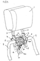
- in einer perspektivischen Darstellung die Integration einer vorteilhaften Ausführungsform der erfindungsgemäßen aktiven Kopfstütze in das Rückenlehnen-Gestell eines Kraftfahrzeug-Sitzes,
- Fig. 2
- einen mittigen Längsschnitt durch die aktive Kopfstütze nach Fig. 1,
- Fig. 3
- einen vergrößerten Ausschnitt aus dem Längsschnitt nach Fig. 2 unter Darstellung der lösbaren Arretierung für die, durch eine Drehfeder vorgespannte, Kopfstütze sowie der Verriegelung der Kopfstütze gegen eine Verschwenkung nach hinten,
- Fig. 4
- in einer perspektivischen Ausschnitt-Darstellung die Anordnung des Auslösesystems an dem Kopfstützen-Gehäuse,
- Fig. 5
- zwei Schnitt-Darstellungen entsprechend Fig. 3, mit der vorgespannten Kopfstütze im Figurenteil A und der ausgelösten Kopfstütze im Figurenteil B, und
- Fig. 6
- in zwei überlagerten perspektivischen Darstellungen analog Fig. 1 die vorgespannte und die ausgelöste Kopfstütze.
- Fig. 1
- a perspective view of the integration of an advantageous embodiment of the active headrest according to the invention in the backrest frame of a motor vehicle seat,
- Fig. 2
- 2 shows a central longitudinal section through the active headrest according to FIG. 1,
- Fig. 3
- 2 shows an enlarged section from the longitudinal section according to FIG. 2, showing the releasable locking device for the headrest, which is prestressed by a torsion spring, and the locking of the headrest against pivoting to the rear,
- Fig. 4
- the arrangement of the release system on the headrest housing in a perspective cutout representation,
- Fig. 5
- 3, with the prestressed headrest in part A and the triggered headrest in part B, and
- Fig. 6
- in two superimposed perspective representations analogous to FIG. 1, the prestressed and the triggered headrest.
Die Zeichnung zeigt in verschiedenen Ansichten und Darstellungsarten ein bevorzugtes Ausführungsbeispiel der Erfindung, ohne daß diese darauf beschränkt wäre. The drawing shows various views and types of representation preferred embodiment of the invention, without this would be limited.
Eine auf übliche Weise aufgepolsterte Kopfstütze 1 weist zwei Verstellrohre 2
auf, die jeweils in einer Lagerhülse 3 verschiebbar geführt sind. Klemmringe 4
in Verbindung mit geschlitzten oberen Enden der Lagerhülsen sorgen dabei in
konventioneller Weise für einen reibbehafteten Sitz der Verstellrohre 2.A
Beide Verstellrohre 2 sind integraler Teil einer rechteckförmig ausgebildeten
Wippe 5, die aus Gewichts- und Festigkeitsgründen strahlenkranzartig
strukturiert ist. An der rückwärtigen Seite der Wippe 5 sind oben Lager 6 für
eine Welle 7 angebracht, die mit ihren beiden Enden in Halterungen 8 am
Gestell 9 der Rückenlehne eines Kraftfährzeug-Sitzes drehbeweglich gehalten
ist. Um die durch diese Welle 7 vorgegebene Achse ist daher die Kopfstütze 1
mit ihren Verstellrohren 2 und der zugehörigen Wippe 5 um eine horizontale
Achse drehbeweglich im Gestell 9 der Rückenlehne integriert.Both
Auf der Welle 7 sitzt koaxial an beiden Enden jeweils eine Drehfeder 10, die
sich jeweils mit ihrem einen Ende 10 a an einem Fortsatz 5 a der Wippe 5 und
mit ihrem anderen Ende 10 b an einem mit dem Gestell 9 fest verbundenen
Gehäuse 11 federvorgespannt abstützt. Der Drehsinn der Drehfeder ist dabei
so, daß die Vorspannung die Kopfstütze 1 nach vorne zu verdrehen versucht.On the
Durch eine lösbare mechanische Arretierung, die im folgenden beschrieben
wird, wird die Kopfstütze 1 im normalen betrieblichen Zustand
federvorgespannt für eine Bewegung nach vorne arretiert. Die Arretierung
umfaßt zunächst einen Verstellhebel 12, der mit einem Ende in einem
Lagerfortsatz 5 b am unteren Steg der Wippe 5 angelenkt und der mit dem
anderen Ende mit einem Auslösehebel 13 drehbeweglich verbunden ist. Der
Auslösehebel 13 ist um eine Achse 13 a drehbeweglich an dem Gehäuse 11,
vorgespannt durch einen Spanndraht 14, angelenkt. Die Vorspannung durch
den Spanndraht 14 ist dabei so gerichtet, daß sie bei Freigabe des
Auslösehebels 13 diesen im Uhrzeigersinn verdreht. By a releasable mechanical lock, described below
is, the
Das Gehäuse 11 besitzt, wie insbesondere aus der Fig. 4 hervorgeht, einen
unteren Fortsatz 11 a, auf dem ein Auslösemagnet 15 mit einem beweglichen,
metallischen Stift 15 a, der bei Aktivierung des Auslösemagneten eingezogen
wird, und einem Arretierkopf 15 b, mittels einer Halterung 16 fest angebracht
ist. Im normalen Betriebszustand (Fig. 5 A) ist dabei der untere Arm des
Auslösehebels 13 im Arretierkopf 15 b mittels des Stiftes 15 a arretiert.As can be seen in particular from FIG. 4, the
Zum Verriegeln der Kopfstütze 1 gegen eine Bewegung nach hinten ist eine
mechanische Verriegelungsanordnung vorgesehen, die im Ausführungsbeispiel
durch einen Zahnsegmentfortsatz 17 an der Wippe 5 in Verbindung mit einem
Sperrstift 18, der verschiebbar in dem Gehäuse 11 gelagert ist, gebildet ist. Im
normalen Betriebszustand (Fig. 5 A), begrenzt durch den Anschlag 19, rastet
der Sperrstift 18 in der äußersten linken Zahnlücke ein. Bei einer
Schwenkbewegung der Kopfstütze 1 nach Freigabe des Auslösehebels 13 (Fig.
5 B) "ratscht" das Zahnsegment über den Sperrstift hinweg, bis die Wippe an
der Gehäusewand des Gehäuses 11, die insoweit als Begrenzung dient,
anschlägt. Sowohl in dieser Stellung als auch in sämtlichen Zwischenstellungen
ist die Kopfstütze 1 gegen ein Verschwenken nach hinten verriegelt, da sofort
der Sperrstift in die nächste Zahnlücke einrasten würde. Durch ein
vorübergehendes Verschieben des Sperrstiftes kann nach einer Auslösung die
Kopfstütze 1 in die ursprüngliche Lage zurückgeschwenkt, d.h. reversiert
werden. Die Kopfstütze wird zweckmäßig mit einem Dämpfer versehen,
welche die Vorwärtsbewegung der Kopfstütze nach ihrer Auslösung dämpft
bzw. verzögert unter Verringerung der Aufprallgeschwindigkeit der Wippe 5
an den Anschlag 11. Der Dämpfer kann aus einem elastisch verformbaren
Material, z.B. PU-Schaum, einem Gummielement, einem Luftpolster, oder
ähnlichen Gebilden bestehen. Auch die Anordnung einer Druckfeder 20 am
Anschlag 11 gemäß Fig. 5 A ist denkbar.To lock the
Die erfindungsgemäße Kopfstütze arbeitet wie folgt: The headrest according to the invention works as follows:
In der betrieblichen Normalposition (Figuren 1, 2, 3 und 5 A) ist die
mechanische Arretierung aktiviert und hält die Kopfstütze 1 gegen die Kraft
der beiden vorgespannten Drehfedern 10 in Position. Stellt ein nicht
dargestellter konventioneller Sensor einen Heckaufprall fest, aktiviert er den
Auslösemagneten 15, der daraufhin den Stift 15 a einzieht. Dadurch wird der
Auslösehebel 13 freigegeben, der durch die Vorspannkraft des Spanndrahtes 14
im Uhrzeigersinn verdreht wird. Dadurch verdreht sich der Verstellhebel 12
nach unten und die Drehfedern 10 können die Wippe 5 im Uhrzeigersinn um
die Achse 7 verschwenken, so daß die Kopfstütze 1 nach vorne, dem Kopf des
Insassen entgegen, bewegt wird. Dieser Zustand ist in Fig. 5 B dargestellt, in
Verbindung mit Fig. 6, die die relative Verstellbewegung zeigt.In the normal operational position (Figures 1, 2, 3 and 5 A) is the
mechanical lock activates and holds the
Der Sensor kann durch einen auf Beschleunigungen ansprechenden Fühler
gebildet werden, der, ähnlich wie bei der Auslösung eines Airbags, bei einem
bestimmten Beschleunigungswert ein elektrisches Signal abgibt, welches das
elektromagnetische Auslösesystem, den Crashmagneten 15, aktiviert und den
Auslösehebel freigibt.The sensor can be activated by a sensor that responds to accelerations
are formed, which, similar to the deployment of an airbag, at a
certain acceleration value gives an electrical signal, which the
electromagnetic release system, the
Der Sensor kann auch ein in dem Fahrzeugsitz integrierter Drucksensor sein,
der bei einer auf ihn ausgeübten vorbestimmten Kraft einen elektrischen Impuls
abgibt, der den Auslösemagneten 15 aktiviert.The sensor can also be a pressure sensor integrated in the vehicle seat,
an electrical pulse when a predetermined force is exerted on it
emits, which activates the
Neben diesen elektrischen Sensoren kann auch ein mechanischer Sensor vorgesehen sein, der beispielsweise durch eine im Fahrzeug-Sitz integrierte flächige Druckplatte gebildet wird, die über Hebel, Seile, Züge oder dergleichen mit der Arretierung des Auslösehebels im lösbaren Wirkeingriff steht.In addition to these electrical sensors, a mechanical sensor can also be used be provided, for example, by an integrated in the vehicle seat flat pressure plate is formed, the lever, ropes, trains or the same with the locking of the release lever in releasable operative engagement stands.
Anstelle der Arretierung der Wippe 5 mittels des gelenkig miteinander
verbundenen Doppel-Hebelsystems 12, 13, 14 können auch andere bekannte
lösbare Arretierungen vorgesehen werden, die im Auslösefall ein
Verschwenken der Kopfstütze gewährleisten.Instead of locking the
Anstelle der beiden Drehfedern 10 kann auf der Welle 7 auch eine einzige
durchgehende Drehfeder verwendet werden. Auch andere Federtypen,
beispielsweise Torsionsfedern, Drehstabfedern oder dergleichen sind
anwendbar.Instead of the two torsion springs 10, a single one can also be on the
Wenngleich die mechanische Verriegelung über das Zahnsegment 17 und den
Sperrstift 18, der auch durch eine Sperrklinke ersetzbar ist, eine bevorzugte
Ausführungsförm darstellt, sind auch andere mechanische
Verriegelungssysteme, die ein Zurückfedern der Kopfstütze 1 verhindern,
anwendbar.Although the mechanical locking via the
Claims (8)
Applications Claiming Priority (2)
| Application Number | Priority Date | Filing Date | Title |
|---|---|---|---|
| DE19924236 | 1999-05-27 | ||
| DE19924236A DE19924236C1 (en) | 1999-05-27 | 1999-05-27 | Active headrest for automobile passenger seat has release system coupled to rear impact sensor for controlled release of mechanical catch allowing headrest to pivot forwards via spring-loaded device |
Publications (2)
| Publication Number | Publication Date |
|---|---|
| EP1055553A2 true EP1055553A2 (en) | 2000-11-29 |
| EP1055553A3 EP1055553A3 (en) | 2003-01-22 |
Family
ID=7909316
Family Applications (1)
| Application Number | Title | Priority Date | Filing Date |
|---|---|---|---|
| EP00109841A Withdrawn EP1055553A3 (en) | 1999-05-27 | 2000-05-10 | Active head rest for automotive vehicle seats |
Country Status (2)
| Country | Link |
|---|---|
| EP (1) | EP1055553A3 (en) |
| DE (1) | DE19924236C1 (en) |
Cited By (5)
| Publication number | Priority date | Publication date | Assignee | Title |
|---|---|---|---|---|
| EP1097837A3 (en) * | 1999-11-08 | 2002-02-13 | Illinois Tool Works Inc. | Headrest assembly |
| DE10148386A1 (en) * | 2001-09-29 | 2003-04-24 | Ina Schaeffler Kg | Non-return system for car head rest mounting comprises shaft and sleeve enclosing locking sleeve between them, shaft having toothed flange on inner end which fits into corresponding seating on frame |
| WO2003091062A1 (en) * | 2002-04-24 | 2003-11-06 | Johnson Controls Automotive Systems Corporation | Seat back for vehicle |
| GB2398236A (en) * | 2003-02-06 | 2004-08-18 | Lear Corp | Anti-backdriving active head restraint in a vehicle seat |
| CN108944594A (en) * | 2018-08-02 | 2018-12-07 | 安徽江淮汽车集团股份有限公司 | Chair framework |
Families Citing this family (11)
| Publication number | Priority date | Publication date | Assignee | Title |
|---|---|---|---|---|
| JP2003080985A (en) * | 2001-06-26 | 2003-03-19 | Nhk Spring Co Ltd | Automotive seat device |
| KR100461109B1 (en) * | 2001-08-09 | 2004-12-13 | 현대자동차주식회사 | Headrest apparatus for protecting neck |
| DE50205220D1 (en) * | 2001-09-10 | 2006-01-12 | Johnson Controls Gmbh | BACKREST FOR VEHICLE SEAT |
| DE20114944U1 (en) * | 2001-09-10 | 2003-01-30 | Johnson Controls Gmbh | Backrest for vehicle seat |
| DE10155263C1 (en) * | 2001-11-09 | 2003-01-02 | Faurecia Autositze Gmbh & Co | Back rest for a motor vehicle seat comprises a support structure for a head rest, and a fixing device consisting of a permanent magnet and a metal bearing region |
| NL1020975C2 (en) * | 2002-07-02 | 2004-01-06 | Whiplash Preventie Systems Hol | Chair, especially vehicle seat, includes device for moving headrest in response to collision impact in order to prevent whiplash |
| JP4133059B2 (en) | 2002-07-18 | 2008-08-13 | 日本発条株式会社 | Vehicle seat having a front movable headrest |
| DE10246475B4 (en) * | 2002-09-27 | 2006-10-19 | Brose Fahrzeugteile Gmbh & Co. Kommanditgesellschaft, Coburg | Headrest assembly for a motor vehicle seat |
| DE10313800A1 (en) * | 2003-03-20 | 2004-09-30 | Brose Fahrzeugteile Gmbh & Co. Kommanditgesellschaft, Coburg | Headrest arrangement for a motor vehicle seat |
| DE102004006873B3 (en) | 2004-02-12 | 2005-06-30 | Faurecia Autositze Gmbh & Co. Kg | Automobile passenger seat with active headrest supported from backrest frame and locked in deployed position via a spring-loaded blocking device |
| JP5720510B2 (en) | 2011-09-20 | 2015-05-20 | トヨタ自動車株式会社 | Vehicle seat |
Family Cites Families (5)
| Publication number | Priority date | Publication date | Assignee | Title |
|---|---|---|---|---|
| AU2397984A (en) * | 1984-02-01 | 1985-08-08 | Tachikawa Spring Co. Ltd. | Head rest |
| US5378043A (en) * | 1993-06-01 | 1995-01-03 | General Motors Corporation | Vehicle pivotal headrest |
| GB2316862A (en) * | 1996-09-05 | 1998-03-11 | Autoliv Dev | Vehicle seat headrest |
| SE510735C2 (en) * | 1996-09-06 | 1999-06-21 | Saab Automobile | Vehicle seat equipped with a headrest |
| JPH10138813A (en) * | 1996-11-08 | 1998-05-26 | Takashimaya Nippatsu Kogyo Kk | Headrest device for vehicle |
-
1999
- 1999-05-27 DE DE19924236A patent/DE19924236C1/en not_active Expired - Fee Related
-
2000
- 2000-05-10 EP EP00109841A patent/EP1055553A3/en not_active Withdrawn
Non-Patent Citations (1)
| Title |
|---|
| AUTOMOBIL-ENTWICKLUNG, March 1999 (1999-03-01), pages 12 |
Cited By (7)
| Publication number | Priority date | Publication date | Assignee | Title |
|---|---|---|---|---|
| EP1097837A3 (en) * | 1999-11-08 | 2002-02-13 | Illinois Tool Works Inc. | Headrest assembly |
| US6789850B1 (en) | 1999-11-08 | 2004-09-14 | Illinois Tool Works Inc. | Headrest assembly |
| DE10148386A1 (en) * | 2001-09-29 | 2003-04-24 | Ina Schaeffler Kg | Non-return system for car head rest mounting comprises shaft and sleeve enclosing locking sleeve between them, shaft having toothed flange on inner end which fits into corresponding seating on frame |
| WO2003091062A1 (en) * | 2002-04-24 | 2003-11-06 | Johnson Controls Automotive Systems Corporation | Seat back for vehicle |
| GB2398236A (en) * | 2003-02-06 | 2004-08-18 | Lear Corp | Anti-backdriving active head restraint in a vehicle seat |
| GB2398236B (en) * | 2003-02-06 | 2005-04-13 | Lear Corp | Anti-backdriving active head restraint |
| CN108944594A (en) * | 2018-08-02 | 2018-12-07 | 安徽江淮汽车集团股份有限公司 | Chair framework |
Also Published As
| Publication number | Publication date |
|---|---|
| DE19924236C1 (en) | 2000-10-26 |
| EP1055553A3 (en) | 2003-01-22 |
Similar Documents
| Publication | Publication Date | Title |
|---|---|---|
| DE19924236C1 (en) | Active headrest for automobile passenger seat has release system coupled to rear impact sensor for controlled release of mechanical catch allowing headrest to pivot forwards via spring-loaded device | |
| DE19853981B4 (en) | Automotive seat | |
| DE2410193C2 (en) | ||
| DE19850758B4 (en) | Headrest assembly for a backrest of a vehicle seat | |
| DE102005033445B4 (en) | Trigger mechanism for impact reaction devices in a motor vehicle seat | |
| EP1608529B1 (en) | Head rest arrangement for a motor vehicle seat | |
| DE4137719A1 (en) | AIRBAG SYSTEM FOR A SELF-DRIVING VEHICLE | |
| EP1193114A1 (en) | Headrest | |
| DE19817980C2 (en) | Vehicle seat with a headrest | |
| DE3841688A1 (en) | Motor-vehicle seat with an approximately U-shaped bar assigned to the seat cushion | |
| WO2003022624A1 (en) | Backrest for a vehicle seat | |
| DE4446595A1 (en) | Vehicle seat with head restraint esp. for children | |
| DE102005007428A1 (en) | Motor vehicle seat, has energy absorption device attached to vehicle seat so that erecting movement of rest part or upper part of body of seat user takes place under energy absorption, where absorption device includes energy absorption unit | |
| DE2708461A1 (en) | Safety catch for adjustable car seat - has inertial ratchet to lock back-rest joint in collision | |
| DE102017203421A1 (en) | Restraint system and method for controlling a restraint system in a vehicle | |
| DE102007062361A1 (en) | Vehicle seat, has safety unit movable from normal position into function position, and traction unit of safety unit arranged in area in safety position, where traction unit forms lateral passenger support | |
| DE102004062944A1 (en) | Seatback reclining device of vehicle, uses large and small diameter winding portions formed in reclining shaft coupled to main and subsidiary seatbacks to hold spiral springs of smaller and larger number of windings | |
| DE10030549A1 (en) | Vehicle seat especially for private car has head restraint part movable away from backrest frame when driven by drive device in event of rear impact crash | |
| EP1420979B1 (en) | Arrangement of a headrest on a vehicle seat especilally in the event of a rear-end collision | |
| DE4212254C1 (en) | Swivel mechanism for car seat squab support - has swivel actuating, prestressed, spring, engaging seat frame and leverage | |
| DE2247921A1 (en) | SEAT WITH ADJUSTABLE BACKREST | |
| EP1545930A1 (en) | Headrest arrangement for the seat of a motor vehicle | |
| WO2018202802A1 (en) | Vehicle seat | |
| DE10201092A1 (en) | Safety device for motor vehicle seat benches has inertia body adjusted in position by acceleration or deceleration forces, and acting with locking element to lock into securing rail under seat | |
| DE10052838A1 (en) | Centre arm rest for vehicles is held secure at high accelerations by extending locking bolt which at low acceleration is positioned by detent device |
Legal Events
| Date | Code | Title | Description |
|---|---|---|---|
| PUAI | Public reference made under article 153(3) epc to a published international application that has entered the european phase |
Free format text: ORIGINAL CODE: 0009012 |
|
| AK | Designated contracting states |
Kind code of ref document: A2 Designated state(s): AT BE CH CY DE DK ES FI FR GB GR IE IT LI LU MC NL PT SE |
|
| AX | Request for extension of the european patent |
Free format text: AL;LT;LV;MK;RO;SI |
|
| PUAL | Search report despatched |
Free format text: ORIGINAL CODE: 0009013 |
|
| AK | Designated contracting states |
Kind code of ref document: A3 Designated state(s): AT BE CH CY DE DK ES FI FR GB GR IE IT LI LU MC NL PT SE |
|
| AX | Request for extension of the european patent |
Free format text: AL;LT;LV;MK;RO;SI |
|
| RIC1 | Information provided on ipc code assigned before grant |
Free format text: 7B 60N 2/48 A, 7B 60N 2/427 B |
|
| 17P | Request for examination filed |
Effective date: 20030408 |
|
| AKX | Designation fees paid |
Designated state(s): DE FR GB IT |
|
| 17Q | First examination report despatched |
Effective date: 20040129 |
|
| GRAP | Despatch of communication of intention to grant a patent |
Free format text: ORIGINAL CODE: EPIDOSNIGR1 |
|
| STAA | Information on the status of an ep patent application or granted ep patent |
Free format text: STATUS: THE APPLICATION HAS BEEN WITHDRAWN |
|
| 18W | Application withdrawn |
Effective date: 20060622 |