EP1054830B1 - Method in winding of a web - Google Patents
Method in winding of a web Download PDFInfo
- Publication number
- EP1054830B1 EP1054830B1 EP99902561A EP99902561A EP1054830B1 EP 1054830 B1 EP1054830 B1 EP 1054830B1 EP 99902561 A EP99902561 A EP 99902561A EP 99902561 A EP99902561 A EP 99902561A EP 1054830 B1 EP1054830 B1 EP 1054830B1
- Authority
- EP
- European Patent Office
- Prior art keywords
- roll
- support members
- measurement
- web
- relative positions
- Prior art date
- Legal status (The legal status is an assumption and is not a legal conclusion. Google has not performed a legal analysis and makes no representation as to the accuracy of the status listed.)
- Expired - Lifetime
Links
Images


Classifications
-
- B—PERFORMING OPERATIONS; TRANSPORTING
- B65—CONVEYING; PACKING; STORING; HANDLING THIN OR FILAMENTARY MATERIAL
- B65H—HANDLING THIN OR FILAMENTARY MATERIAL, e.g. SHEETS, WEBS, CABLES
- B65H23/00—Registering, tensioning, smoothing or guiding webs
- B65H23/02—Registering, tensioning, smoothing or guiding webs transversely
- B65H23/032—Controlling transverse register of web
- B65H23/0328—Controlling transverse register of web by moving the winding device
-
- B—PERFORMING OPERATIONS; TRANSPORTING
- B65—CONVEYING; PACKING; STORING; HANDLING THIN OR FILAMENTARY MATERIAL
- B65H—HANDLING THIN OR FILAMENTARY MATERIAL, e.g. SHEETS, WEBS, CABLES
- B65H18/00—Winding webs
- B65H18/02—Supporting web roll
- B65H18/06—Lateral-supporting
-
- B—PERFORMING OPERATIONS; TRANSPORTING
- B65—CONVEYING; PACKING; STORING; HANDLING THIN OR FILAMENTARY MATERIAL
- B65H—HANDLING THIN OR FILAMENTARY MATERIAL, e.g. SHEETS, WEBS, CABLES
- B65H2301/00—Handling processes for sheets or webs
- B65H2301/40—Type of handling process
- B65H2301/41—Winding, unwinding
- B65H2301/414—Winding
- B65H2301/4148—Winding slitting
-
- B—PERFORMING OPERATIONS; TRANSPORTING
- B65—CONVEYING; PACKING; STORING; HANDLING THIN OR FILAMENTARY MATERIAL
- B65H—HANDLING THIN OR FILAMENTARY MATERIAL, e.g. SHEETS, WEBS, CABLES
- B65H2405/00—Parts for holding the handled material
- B65H2405/40—Holders, supports for rolls
- B65H2405/42—Supports for rolls fully removable from the handling machine
- B65H2405/422—Trolley, cart, i.e. support movable on floor
-
- B—PERFORMING OPERATIONS; TRANSPORTING
- B65—CONVEYING; PACKING; STORING; HANDLING THIN OR FILAMENTARY MATERIAL
- B65H—HANDLING THIN OR FILAMENTARY MATERIAL, e.g. SHEETS, WEBS, CABLES
- B65H2511/00—Dimensions; Position; Numbers; Identification; Occurrences
- B65H2511/10—Size; Dimensions
- B65H2511/16—Irregularities, e.g. protuberances
-
- B—PERFORMING OPERATIONS; TRANSPORTING
- B65—CONVEYING; PACKING; STORING; HANDLING THIN OR FILAMENTARY MATERIAL
- B65H—HANDLING THIN OR FILAMENTARY MATERIAL, e.g. SHEETS, WEBS, CABLES
- B65H2515/00—Physical entities not provided for in groups B65H2511/00 or B65H2513/00
- B65H2515/30—Forces; Stresses
Definitions
- the web is wound onto a spool on support of a support roll and through the nip formed between the support roll and the roll that is being produced.
- the spool is supported at least partly by means of a support member fitted in the centre of the spool.
- the spool and the roll are supported and/or loaded by means of a device whose position can be varied.
- the loading and support units of said device are shifted substantially in a plane passing through the axes of the support roll and of the roll that is being produced in order to load and/or to support the roll that is being produced in the winding position.
- the method in accordance with the invention can be utilized in all such winding methods in which the direction of arrival of the web to be wound onto the roll can be regulated in relation to the axis of the roll or in which the winding is carried out by means of a winding nip in which the distribution of loading in the direction of width of the nip can be regulated.
- the method is also suitable for nip-free centre-drive winding in which the tension of the web on the roll is regulated exclusively by means of the torque of rotation applied to the shaft of the web roll.
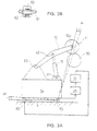
- Fig. 1 is a schematic axonometric view
- Fig. 2 a side view of a centre-drive winder.
- Figs. 1 and 2 also illustrate a mode in accordance with the present invention for regulation of the nip line between the roll 11 that is being formed and the support roll 50 in the centre-drive winder.
- a centre-drive winder is understood in particular as a winder type used in connection with a slitter-winder, in which the rolls formed out of component webs are supported, each of them separately, from the ends of their roll spools and at least from one point at the side of the web roll by means of a support roll or an equivalent support member.
- a second loading cylinder 17 has been attached from one of its ends by means of an articulated joint.
- the other end of the first loading cylinder 16 has been attached by means of an articulated joint 41 to the first sledge 14, and the other end of the second loading cylinder 17 has been attached similarly by means of an articulated joint to the second sledge 15.
- a first force metering detector 20 has been fitted, and similarly, in connection with the second sledge 15, a second force metering detector 21 has been fitted.
- the force metering detectors 20,21 can be placed, for example, between the sledges 14,15 and their brakes. Alternatively, the force metering detectors 20,21 can be placed in connection with the support seats of the roll 11 that is being formed.
- the force metering detectors 20.21 meter the force acting in the direction of the axis of the roll spool, which force is transferred from the roll spool to the winding arms 12,13 and further to the sledges 14,15.
- the support point 12a of the roll 11 on the support arm 12 attached to the sledge 14 is shifted by the angle ⁇ , and when the other sledge 15 remains stationary, the direction of the axis of the roll 11 is altered in relation to the running direction of the web that is being fed onto the roll, and the axial force in the interior of the roil 11 is compensated for, in which case formation of an error of shape in the roll 11 is prevented.
- the nip lines N 1 and N 2 come together, and at the roll 11 end that is shifted the nip lines N 1 and N 2 are placed at the distance ⁇ x from one another.
- axial shifting of the web wound onto the roll 11 can be prevented, so that the ends of the roll 11 to be wound become planar.
- the side plane of the roll 11 can also be measured directly, e.g., by means of photocells, an ultrasound detector, or by means of capacitive or contact measurement.
- said metering of lateral forces is, however, preferable, because by its means it is possible to see considerably earlier indirectly when such a force arising from the winding nip or from profile errors in the web is applied to the rell 11 as attempts to divert the web layers to be wound onto the roll 11 from their desired position, and measures of correction can be initiated earlier.
Landscapes
- Replacement Of Web Rolls (AREA)
- Winding Of Webs (AREA)
- Sanitary Thin Papers (AREA)
- Control Of Vehicles With Linear Motors And Vehicles That Are Magnetically Levitated (AREA)
- Train Traffic Observation, Control, And Security (AREA)
- Registering, Tensioning, Guiding Webs, And Rollers Therefor (AREA)
- Transition And Organic Metals Composition Catalysts For Addition Polymerization (AREA)
- Mechanical Operated Clutches (AREA)
- Control Of Combustion (AREA)
- Polishing Bodies And Polishing Tools (AREA)
- Formation And Processing Of Food Products (AREA)
- Reduction Rolling/Reduction Stand/Operation Of Reduction Machine (AREA)
Abstract
Description
Claims (10)
- A method in winding of a web, wherein the roll (11) that is being formed is supported in the direction of the axis of the roll (11) by means of a first (12) and a second (13) support member placed at both sides of the roll (11), characterized in that the shape of the end of the roll (11) that is being formed is measured by means of indirect or direct measurement, and the relative positions of the support members (12,13) in relation to one another are regulated based on the measurement, in which connection any defects of shape in the ends of the roll (11) that is being formed can be prevented.
- A method as claimed in claim 1, characterized in that, as an indirect method of measurement, the force applied in the axial direction of the roll (11) that is being formed is metered at least in connection with the support member (12,13) that supports one end of the roll, and the relative positions of the support members (12. 13) are regulated based on said metering.
- A method as claimed in claim 1, characterized in that the axial force applied to the roll (11) that is being formed is metered in connection with the support members (12,13) at both ends of the roll, and the relative positions of the support members (12,13) are regulated based on said metering.
- A method as claimed in claim 3, characterized in that the resultant of the axial forces applied to the roll (11) that is being formed is determined as the difference between the metered support forces, and the relative positions (12,13) of the support members are regulated based on said metering.
- A method as claimed in any of the claims 1 to 4, characterized in that the relative positions of the support members (12,13) of the roll (11) that is being formed are regulated based on the data obtained from the metering by increasing or reducing the load applied to the roll (11) that is being formed through one support member (12, 13).
- A method as claimed in any of the claims 1 to 5, characterized in that the relative positions of the support members (12,13) of the roll (11) that is being formed are regulated based on the data obtained from the metering by shifting one of the support members (12, 13) so that the running direction of the web that is passed onto the face of the roll (11) that is being formed in relation to the axis of the roll (11) that is being formed is changed.
- A method as claimed in claim 1, characterized in that the location of the web layers that are the topmost layers, at each particular time, on the roll (11) that is being formed is measured in the axial direction of the roll (11) by means of a contact-free method of measurement, and the relative positions of the support members (12,13) are regulated based on the measurement.
- A method as claimed in claim 1, characterized in that the location of the web layers that are the topmost layers, at each particular time, on the roll (11) that is being formed is measured in the axial direction of the roll (11) by means of a method of measurement with contact, and the relative positions of the support members (12,13) are regulated based on the measurement.
- A method as claimed in claim 7 or 8, characterized in that the relative positions of the support members (12,13) of the roll (11) that is being formed are regulated based on the data received from the measurement by increasing or reducing the load applied through one of the support members to the roll (11) that is being formed.
- A method as claimed in any of the claims 7 to 9, characterized in that the relative positions of the support members (12, 13) of the roll (11) that is being formed are regulated based on the data received from the measurement by shifting one of the support members (12,13) so that the running direction of the web passed onto the face of the roll (11) that is being formed in relation to the axis of the roll (11) that is being formed is changed.
Applications Claiming Priority (3)
| Application Number | Priority Date | Filing Date | Title |
|---|---|---|---|
| FI980252A FI106446B (en) | 1998-02-04 | 1998-02-04 | Method of web winding |
| FI980252 | 1998-02-04 | ||
| PCT/FI1999/000070 WO1999040003A1 (en) | 1998-02-04 | 1999-02-02 | Method in winding of a web |
Publications (2)
| Publication Number | Publication Date |
|---|---|
| EP1054830A1 EP1054830A1 (en) | 2000-11-29 |
| EP1054830B1 true EP1054830B1 (en) | 2002-05-22 |
Family
ID=8550703
Family Applications (1)
| Application Number | Title | Priority Date | Filing Date |
|---|---|---|---|
| EP99902561A Expired - Lifetime EP1054830B1 (en) | 1998-02-04 | 1999-02-02 | Method in winding of a web |
Country Status (9)
| Country | Link |
|---|---|
| US (1) | US6095452A (en) |
| EP (1) | EP1054830B1 (en) |
| JP (1) | JP4328017B2 (en) |
| AT (1) | ATE217850T1 (en) |
| AU (1) | AU2280699A (en) |
| DE (1) | DE69901540T2 (en) |
| FI (1) | FI106446B (en) |
| NO (1) | NO316219B1 (en) |
| WO (1) | WO1999040003A1 (en) |
Families Citing this family (8)
| Publication number | Priority date | Publication date | Assignee | Title |
|---|---|---|---|---|
| DE69926592T2 (en) * | 1998-03-26 | 2006-04-06 | Jfe Steel Corp. | METHOD AND DEVICE FOR WINDING METAL FOIL |
| FI107908B (en) * | 1998-11-04 | 2001-10-31 | Metso Paper Inc | Method and apparatus for checking the structure of the roller |
| FI105803B (en) * | 1999-03-30 | 2000-10-13 | Valmet Corp | Method and apparatus for continuous rolling of a roll of paper |
| US6669818B2 (en) * | 2000-06-28 | 2003-12-30 | Metso Paper Karlstad Ab | Shortened layout from dryer to reel in tissue machine |
| DE10234958A1 (en) * | 2002-07-31 | 2004-02-12 | Voith Paper Patent Gmbh | Method for transferring a threading strip of a material web onto a winding device |
| DE10250863B4 (en) * | 2002-10-31 | 2005-06-02 | Brückner Maschinenbau GmbH | Winding device for web-shaped materials, in particular plastic films |
| DE10327245A1 (en) * | 2003-06-17 | 2005-01-05 | Voith Paper Patent Gmbh | rewinder |
| JP4982313B2 (en) * | 2007-09-20 | 2012-07-25 | リョービ株式会社 | Transfer film winding method and printing paper transfer device |
Family Cites Families (11)
| Publication number | Priority date | Publication date | Assignee | Title |
|---|---|---|---|---|
| DE1219576B (en) * | 1962-12-10 | 1966-06-23 | Continental Elektro Ind Ag | Device for regulating the middle position of the strip in the form of a strip |
| US3570735A (en) * | 1968-11-18 | 1971-03-16 | Gpe Controls Inc | Method and apparatus of guiding moving webs |
| JPS5221139B1 (en) * | 1971-05-27 | 1977-06-08 | ||
| US4500045A (en) * | 1983-08-29 | 1985-02-19 | Xerox Corporation | Laterally translatable roll apparatus |
| JPS6242378A (en) * | 1985-08-19 | 1987-02-24 | Fuji Photo Film Co Ltd | Method and apparatus for winding magnetic tape |
| DE3721969C2 (en) * | 1987-07-03 | 1994-02-10 | Reifenhaeuser Masch | Device for winding a film web, in particular a plastic film web, into a film roll on a winding core |
| DE3924612A1 (en) * | 1989-07-26 | 1991-01-31 | Jagenberg Ag | SUPPORT ROLLER REWINDING MACHINE FOR REWINDING MATERIALS |
| DE4232363C2 (en) * | 1992-09-26 | 1995-11-30 | Kloeckner Er We Pa Gmbh | Device for the continuous winding of material webs |
| DE4408863C2 (en) * | 1994-03-16 | 1998-07-09 | Kampf Gmbh & Co Maschf | Device for winding a material web, in particular a plastic film web |
| FI100467B (en) * | 1994-05-26 | 1997-12-15 | Valmet Corp | Method and apparatus for web rolling |
| EP0919499B1 (en) * | 1997-11-29 | 2003-07-02 | Meinan Machinery Works, Inc. | Veneer reeling apparatus |
-
1998
- 1998-02-04 FI FI980252A patent/FI106446B/en not_active IP Right Cessation
-
1999
- 1999-01-11 US US09/227,808 patent/US6095452A/en not_active Expired - Lifetime
- 1999-02-02 AU AU22806/99A patent/AU2280699A/en not_active Abandoned
- 1999-02-02 DE DE69901540T patent/DE69901540T2/en not_active Expired - Lifetime
- 1999-02-02 EP EP99902561A patent/EP1054830B1/en not_active Expired - Lifetime
- 1999-02-02 WO PCT/FI1999/000070 patent/WO1999040003A1/en active IP Right Grant
- 1999-02-02 AT AT99902561T patent/ATE217850T1/en active
- 1999-02-02 JP JP2000530443A patent/JP4328017B2/en not_active Expired - Fee Related
-
2000
- 2000-07-14 NO NO20003623A patent/NO316219B1/en not_active IP Right Cessation
Also Published As
| Publication number | Publication date |
|---|---|
| NO316219B1 (en) | 2003-12-29 |
| NO20003623L (en) | 2000-09-27 |
| FI980252A0 (en) | 1998-02-04 |
| ATE217850T1 (en) | 2002-06-15 |
| AU2280699A (en) | 1999-08-23 |
| FI106446B (en) | 2001-02-15 |
| JP4328017B2 (en) | 2009-09-09 |
| JP2002502786A (en) | 2002-01-29 |
| WO1999040003A1 (en) | 1999-08-12 |
| DE69901540T2 (en) | 2002-11-21 |
| US6095452A (en) | 2000-08-01 |
| FI980252A (en) | 1999-08-05 |
| DE69901540D1 (en) | 2002-06-27 |
| NO20003623D0 (en) | 2000-07-14 |
| EP1054830A1 (en) | 2000-11-29 |
Similar Documents
| Publication | Publication Date | Title |
|---|---|---|
| EP0642460B1 (en) | Reel wound roll load sensing arrangement | |
| CA2060468C (en) | Method and apparatus for winding a traveling web | |
| US4746076A (en) | Winder device | |
| CA2147764C (en) | Web-winding process and device | |
| CA2319573C (en) | Method and apparatus in reeling of a web | |
| KR100309577B1 (en) | Web winding device | |
| FI118594B (en) | Roller with raised bobbin rail | |
| CA2128533C (en) | Diameter and lateral position sensitive nip pressure controls in a paper winding system | |
| EP1054830B1 (en) | Method in winding of a web | |
| FI121228B (en) | Procedure for rolling a paper or cardboard web and a wheelchair | |
| CA2054250C (en) | Reel-up and method for regulation of the nip pressure in a reel-up | |
| JP2010504216A (en) | Method and apparatus for winding a strip with a winding mandrel. | |
| US2984429A (en) | Single rollstand web handling machine | |
| KR100430127B1 (en) | A paper center-winding method and device therefor | |
| US5154367A (en) | Web winder having driven cams to relieve roller pressure | |
| WO1998055384A1 (en) | Method and apparatus for reeling a traveling paper web | |
| CA2804641C (en) | Method and device for winding of fiber webs, especially of partial paper and board webs | |
| FI108429B (en) | Painotelarullain | |
| CA2306467C (en) | Paper web treatment control system based on energy supplied to a bearing | |
| US7845592B2 (en) | Reel-up and also a method and measuring unit in such a reel-up | |
| US20040056142A1 (en) | Method and device for winding a paper or board web | |
| US6427940B1 (en) | Method and device in winding of a web | |
| CA2331402A1 (en) | Method and device for applying a load to a reel in a reel-up of a paper web |
Legal Events
| Date | Code | Title | Description |
|---|---|---|---|
| PUAI | Public reference made under article 153(3) epc to a published international application that has entered the european phase |
Free format text: ORIGINAL CODE: 0009012 |
|
| 17P | Request for examination filed |
Effective date: 20000731 |
|
| AK | Designated contracting states |
Kind code of ref document: A1 Designated state(s): AT DE FR GB IT SE |
|
| GRAG | Despatch of communication of intention to grant |
Free format text: ORIGINAL CODE: EPIDOS AGRA |
|
| 17Q | First examination report despatched |
Effective date: 20010328 |
|
| GRAG | Despatch of communication of intention to grant |
Free format text: ORIGINAL CODE: EPIDOS AGRA |
|
| GRAH | Despatch of communication of intention to grant a patent |
Free format text: ORIGINAL CODE: EPIDOS IGRA |
|
| RAP1 | Party data changed (applicant data changed or rights of an application transferred) |
Owner name: METSO PAPER, INC. |
|
| GRAH | Despatch of communication of intention to grant a patent |
Free format text: ORIGINAL CODE: EPIDOS IGRA |
|
| GRAA | (expected) grant |
Free format text: ORIGINAL CODE: 0009210 |
|
| REF | Corresponds to: |
Ref document number: 217850 Country of ref document: AT Date of ref document: 20020615 Kind code of ref document: T |
|
| REG | Reference to a national code |
Ref country code: GB Ref legal event code: FG4D |
|
| REF | Corresponds to: |
Ref document number: 69901540 Country of ref document: DE Date of ref document: 20020627 |
|
| ET | Fr: translation filed | ||
| PLBE | No opposition filed within time limit |
Free format text: ORIGINAL CODE: 0009261 |
|
| STAA | Information on the status of an ep patent application or granted ep patent |
Free format text: STATUS: NO OPPOSITION FILED WITHIN TIME LIMIT |
|
| 26N | No opposition filed |
Effective date: 20030225 |
|
| PGFP | Annual fee paid to national office [announced via postgrant information from national office to epo] |
Ref country code: GB Payment date: 20090219 Year of fee payment: 11 |
|
| PGFP | Annual fee paid to national office [announced via postgrant information from national office to epo] |
Ref country code: FR Payment date: 20090213 Year of fee payment: 11 |
|
| GBPC | Gb: european patent ceased through non-payment of renewal fee |
Effective date: 20100202 |
|
| REG | Reference to a national code |
Ref country code: FR Ref legal event code: ST Effective date: 20101029 |
|
| PG25 | Lapsed in a contracting state [announced via postgrant information from national office to epo] |
Ref country code: FR Free format text: LAPSE BECAUSE OF NON-PAYMENT OF DUE FEES Effective date: 20100301 |
|
| PG25 | Lapsed in a contracting state [announced via postgrant information from national office to epo] |
Ref country code: GB Free format text: LAPSE BECAUSE OF NON-PAYMENT OF DUE FEES Effective date: 20100202 |
|
| PGFP | Annual fee paid to national office [announced via postgrant information from national office to epo] |
Ref country code: IT Payment date: 20120224 Year of fee payment: 14 |
|
| PGFP | Annual fee paid to national office [announced via postgrant information from national office to epo] |
Ref country code: SE Payment date: 20130219 Year of fee payment: 15 Ref country code: DE Payment date: 20130219 Year of fee payment: 15 |
|
| PGFP | Annual fee paid to national office [announced via postgrant information from national office to epo] |
Ref country code: AT Payment date: 20130213 Year of fee payment: 15 |
|
| REG | Reference to a national code |
Ref country code: DE Ref legal event code: R119 Ref document number: 69901540 Country of ref document: DE |
|
| REG | Reference to a national code |
Ref country code: SE Ref legal event code: EUG |
|
| REG | Reference to a national code |
Ref country code: AT Ref legal event code: MM01 Ref document number: 217850 Country of ref document: AT Kind code of ref document: T Effective date: 20140202 |
|
| PG25 | Lapsed in a contracting state [announced via postgrant information from national office to epo] |
Ref country code: AT Free format text: LAPSE BECAUSE OF NON-PAYMENT OF DUE FEES Effective date: 20140202 Ref country code: SE Free format text: LAPSE BECAUSE OF NON-PAYMENT OF DUE FEES Effective date: 20140203 |
|
| REG | Reference to a national code |
Ref country code: DE Ref legal event code: R119 Ref document number: 69901540 Country of ref document: DE Effective date: 20140902 |
|
| PG25 | Lapsed in a contracting state [announced via postgrant information from national office to epo] |
Ref country code: DE Free format text: LAPSE BECAUSE OF NON-PAYMENT OF DUE FEES Effective date: 20140902 |
|
| PG25 | Lapsed in a contracting state [announced via postgrant information from national office to epo] |
Ref country code: IT Free format text: LAPSE BECAUSE OF NON-PAYMENT OF DUE FEES Effective date: 20140202 |