EP1054394A2 - Optical recording medium reducing optical spot size. - Google Patents
Optical recording medium reducing optical spot size. Download PDFInfo
- Publication number
- EP1054394A2 EP1054394A2 EP00304112A EP00304112A EP1054394A2 EP 1054394 A2 EP1054394 A2 EP 1054394A2 EP 00304112 A EP00304112 A EP 00304112A EP 00304112 A EP00304112 A EP 00304112A EP 1054394 A2 EP1054394 A2 EP 1054394A2
- Authority
- EP
- European Patent Office
- Prior art keywords
- metal film
- recording medium
- optical recording
- optical
- focusing device
- Prior art date
- Legal status (The legal status is an assumption and is not a legal conclusion. Google has not performed a legal analysis and makes no representation as to the accuracy of the status listed.)
- Granted
Links
Images


Classifications
-
- G—PHYSICS
- G11—INFORMATION STORAGE
- G11B—INFORMATION STORAGE BASED ON RELATIVE MOVEMENT BETWEEN RECORD CARRIER AND TRANSDUCER
- G11B7/00—Recording or reproducing by optical means, e.g. recording using a thermal beam of optical radiation by modifying optical properties or the physical structure, reproducing using an optical beam at lower power by sensing optical properties; Record carriers therefor
- G11B7/24—Record carriers characterised by shape, structure or physical properties, or by the selection of the material
- G11B7/241—Record carriers characterised by shape, structure or physical properties, or by the selection of the material characterised by the selection of the material
- G11B7/252—Record carriers characterised by shape, structure or physical properties, or by the selection of the material characterised by the selection of the material of layers other than recording layers
- G11B7/258—Record carriers characterised by shape, structure or physical properties, or by the selection of the material characterised by the selection of the material of layers other than recording layers of reflective layers
-
- B—PERFORMING OPERATIONS; TRANSPORTING
- B82—NANOTECHNOLOGY
- B82Y—SPECIFIC USES OR APPLICATIONS OF NANOSTRUCTURES; MEASUREMENT OR ANALYSIS OF NANOSTRUCTURES; MANUFACTURE OR TREATMENT OF NANOSTRUCTURES
- B82Y10/00—Nanotechnology for information processing, storage or transmission, e.g. quantum computing or single electron logic
-
- G—PHYSICS
- G11—INFORMATION STORAGE
- G11B—INFORMATION STORAGE BASED ON RELATIVE MOVEMENT BETWEEN RECORD CARRIER AND TRANSDUCER
- G11B7/00—Recording or reproducing by optical means, e.g. recording using a thermal beam of optical radiation by modifying optical properties or the physical structure, reproducing using an optical beam at lower power by sensing optical properties; Record carriers therefor
- G11B7/12—Heads, e.g. forming of the optical beam spot or modulation of the optical beam
- G11B7/122—Flying-type heads, e.g. analogous to Winchester type in magnetic recording
-
- G—PHYSICS
- G11—INFORMATION STORAGE
- G11B—INFORMATION STORAGE BASED ON RELATIVE MOVEMENT BETWEEN RECORD CARRIER AND TRANSDUCER
- G11B7/00—Recording or reproducing by optical means, e.g. recording using a thermal beam of optical radiation by modifying optical properties or the physical structure, reproducing using an optical beam at lower power by sensing optical properties; Record carriers therefor
- G11B7/12—Heads, e.g. forming of the optical beam spot or modulation of the optical beam
- G11B7/135—Means for guiding the beam from the source to the record carrier or from the record carrier to the detector
- G11B7/1372—Lenses
- G11B7/1374—Objective lenses
-
- G—PHYSICS
- G11—INFORMATION STORAGE
- G11B—INFORMATION STORAGE BASED ON RELATIVE MOVEMENT BETWEEN RECORD CARRIER AND TRANSDUCER
- G11B7/00—Recording or reproducing by optical means, e.g. recording using a thermal beam of optical radiation by modifying optical properties or the physical structure, reproducing using an optical beam at lower power by sensing optical properties; Record carriers therefor
- G11B7/12—Heads, e.g. forming of the optical beam spot or modulation of the optical beam
- G11B7/135—Means for guiding the beam from the source to the record carrier or from the record carrier to the detector
- G11B7/1387—Means for guiding the beam from the source to the record carrier or from the record carrier to the detector using the near-field effect
-
- G—PHYSICS
- G11—INFORMATION STORAGE
- G11B—INFORMATION STORAGE BASED ON RELATIVE MOVEMENT BETWEEN RECORD CARRIER AND TRANSDUCER
- G11B7/00—Recording or reproducing by optical means, e.g. recording using a thermal beam of optical radiation by modifying optical properties or the physical structure, reproducing using an optical beam at lower power by sensing optical properties; Record carriers therefor
- G11B7/24—Record carriers characterised by shape, structure or physical properties, or by the selection of the material
-
- G—PHYSICS
- G11—INFORMATION STORAGE
- G11B—INFORMATION STORAGE BASED ON RELATIVE MOVEMENT BETWEEN RECORD CARRIER AND TRANSDUCER
- G11B7/00—Recording or reproducing by optical means, e.g. recording using a thermal beam of optical radiation by modifying optical properties or the physical structure, reproducing using an optical beam at lower power by sensing optical properties; Record carriers therefor
- G11B7/12—Heads, e.g. forming of the optical beam spot or modulation of the optical beam
- G11B7/135—Means for guiding the beam from the source to the record carrier or from the record carrier to the detector
- G11B7/1372—Lenses
- G11B2007/13725—Catadioptric lenses, i.e. having at least one internal reflective surface
Definitions
- the present invention relates to an optical recording medium having a construction which allows the reduction of an optical spot size formed on such a medium.
- a variety of methods for enhancing a recording density in an optical recording medium are being under research and development.
- One of them is a method for reducing an optical spot size formed on an optical recording medium.
- a size d of an optical spot formed on an optical recording medium is determined by ⁇ /(n sin ⁇ ), in which is ⁇ a wavelength of light, n is a refractive index of the optical recording medium, and ⁇ is an incident angle.
- the size of the optical spot can be reduced by adjusting the wavelength of light, the refractive index of the optical recording medium, and the incident angle.
- an aim of preferred embodiments of the present invention to provide an optical recording medium having an enhanced recording density by presenting a new variable which can reduce an optical spot size in addition to a wavelength of light, a refractive index of an optical recording medium, and an incident angle.
- an optical recording medium on which an optical spot is formed by a focusing device comprising: a metal film which is formed on an information recording layer opposing the focusing device, for reflecting and transmitting light incident from the focusing device, wherein a relationship of n1Sin ⁇ 1 ⁇ n2 ⁇ n1 is satisfied wherein n1 is a refractive index of the focusing device, ⁇ 1 is an incident angle, and n2 is a refractive index of the metal film, and wherein n2 is less than one.
- the thickness of said metal film has a value which is less than a wavelength of light used.
- said metal film is formed within a depth of focus of the focusing device.
- said metal film comprises any one of copper, silver, gold and sodium.
- an optical recording medium on which an optical spot is formed by a focusing device comprising: a metal film which is formed on a surface of an information recording layer of the medium furthest away from the focussing device such that, the information recording layer is interposed between the metal film and the focusing device, the metal film, for reflecting and transmitting light incident from the focusing device, wherein a relationship of n1Sin ⁇ 1 ⁇ n2 ⁇ n1 is satisfied wherein, n1 is a refractive index of the focusing device, ⁇ 1 is an incident angle, and n2 is a refractive index of the metal film, and wherein n2 is less than one.
- an objective lens generating near field comprising: a lens portion for reflecting and refracting an incident light and focusing the incident light on information recording layer of an optical recording medium; and a metal film which is formed on the lens portion opposing the information recording layer of the optical recording medium, for reflecting and transmitting light incident from the lens portion, wherein a relationship of n1Sin ⁇ 1 ⁇ n2 ⁇ n1 is satisfied where n1 is a refractive index of the lens portion, ⁇ 1 is an incident angle, and n2 is a refractive index of the metal film, and wherein n2 is less than one.
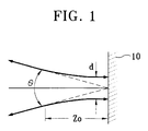
- a metal film which reflects incident light is coated on a general optical recording medium. As shown in Figure 1, a metal film 10 substantially totally (100%) reflects light incident to an optical recording medium and further substantially blocks transmission of the same (substantially 0% transmission).
- a reference symbol Z 0 represents a depth of focus.
- the present invention proposes an optical recording medium on which a thin metal film both reflects and transmits incident light.
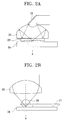
- Figure 2A shows an optical recording medium and a focusing optical system using a near field according to an embodiment of the present invention.
- the focusing optical system using a near field of Figure 2A includes a reflective mirror 21 for reflecting incident light toward an optical recording medium 24, a solid immersion mirror (SIM) 22 for reflecting and refracting the light reflected from the reflective mirror 21, and a slider 23 for moving the SIM 22 in relation to the surface of the optical recording medium 24.
- the slider 23 maintains a distance between the SIM 22 and the optical recording medium 24 to be less than a predetermined length.
- the distance between the SIM 22 and the optical recording medium 24 is called an air gap. It is preferable that the air gap is less than the wavelength of light.
- FIG. 2B shows another focusing optical system using a near field.
- the focusing optical system includes an aspherical lens 25 for refracting incident light, a solid immersion lens (SIL) 26 for focusing the light incident from the aspherical lens 25 on an information recording layer of the optical recording medium 24, and a slider 27 for moving the SIL 26 in relation to the optical recording medium 24.
- SIL solid immersion lens
- Figure 3A is an enlarged view of a portion "A" in Figures 2A and 2B.
- Figure 3A shows a layout of layers in the optical recording medium on which a thin metal film is formed, which is applied commonly to the focusing optical systems of Figures 2A and 2B.
- an information recording layer of the optical recording medium 24 is formed on the plane of the optical recording medium opposing the focusing optical system.
- a metal film 241 is formed on the information recording layer in the optical recording medium 24 according to the present invention. Accordingly, the light incident from the objective lens such as the SIL 26 passes through the metal film 241 and is incident to the information recording layer 242.
- n2 n1 sin ⁇ c (n1 > n2)
- the light incident to the metal film 241 should be incident with an incident angle smaller than the critical angle.
- the constituent condition of the metal film 241 satisfies the following relationship. n1Sin ⁇ 1 ⁇ n2 ⁇ n1.
- the metal used as a metal film 241 is one of metal having a refractive index smaller than one, such suitable metals being, for instance, copper, silver, gold and sodium.
- the thickness of the metal film 241 should have a value which is less than the wavelength of light. It is preferable that the sum of the metal film 241 and the air gap has a value which is less than the wavelength of the light used.
- the thin metal film according to embodiments of the present invention can be formed on the objective lens 26 opposing the optical recording medium.
- the thin metal film 244 can be formed beneath the information recording layer 243, that is, on the other surface of the information recording layer 243 farther from the objective lens 26, interposing the information recording layer 243.
- a thin metal film should be formed within a depth of focus.
- a dielectric can be formed as a protective layer on the metal film 241. Even in this case, It is preferable that sum of the thickness of the metal film, the thickness of the protective layer, and the air gap does not exceed the wavelength of light.
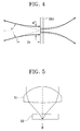
- Figure 4 shows that a part of the light incident from the optical recording medium is reflected and part thereof is transmitted by the thin metal film 241.
- Figure 5 shows an optical recording medium and a focusing optical system using a far field according to another embodiment of the present invention.
- the focusing optical system of Figure 5 includes an objective lens 51 focusing incident light.
- a reference numeral 52 represents an optical recording medium.
- Figure 6 is an enlarged view showing a portion "B" in Figure 5.
- a protective layer 521 of the optical recording medium 52, a thin metal film 522 and an information recording layer 523 are arranged in turn starting from an incident direction of light.
- a relationship of n1Sin ⁇ 1 ⁇ n2 ⁇ n1 is formed among the refractive index n1 of the objective lens 51, the incident angle ⁇ 1 of light and the refractive index n2 of the thin metal film.
- the thin metal film 522 is a coated film formed of any one of copper, silver, gold and sodium whose refractive index is smaller than one.
- the thickness of the thin metal film 522 has a value within the wavelength of light.
- the thin metal film 522 can be formed beneath the information recording layer 523.
- the thin metal film 522 is formed on the information recording layer 523 of the optical recording medium 52 opposing the objective lens 51 or on the other surface of the information recording layer farther from the objective lens, interposing the information recording layer. Therefore, part of light incident to the optical recording medium is reflected and part thereof is transmitted. As a result, the size of the optical spot focused on the optical recording medium 52 is reduced by the function of the metal film.
- the optical spot size can be reduced in a relatively simple manner, thereby providing an effect of enhancing a recording density of the optical recording medium.
Landscapes
- Physics & Mathematics (AREA)
- Engineering & Computer Science (AREA)
- Optics & Photonics (AREA)
- Chemical & Material Sciences (AREA)
- Nanotechnology (AREA)
- Mathematical Physics (AREA)
- Theoretical Computer Science (AREA)
- Crystallography & Structural Chemistry (AREA)
- Optical Record Carriers And Manufacture Thereof (AREA)
- Optical Head (AREA)
Abstract
Description
Claims (6)
- An optical recording medium on which an optical spot is formed by a focusing device (26), the optical recording medium (24) comprising:a metal film (241) which is formed on an information recording layer (242) opposing the focusing device (26), for reflecting and transmitting light incident from the focusing device (26),wherein a relationship of n1Sin1<n2<n1 is satisfied where n1 is a refractive index of the focusing device (26), 1 is an incident angle, and n2 is a refractive index of the metal film (24), and wherein n2 is less than one.
- The optical recording medium of claim 1, wherein the thickness of said metal film (241) has a value which is less than a wavelength of light used.
- The optical recording medium of claim 1 or 2, wherein said metal film (241)is formed within a depth of focus of the focusing device (26).
- The optical recording medium of any preceding claim, wherein said metal film comprises any one of copper, silver, gold and sodium.
- An optical recording medium on which an optical spot is formed by a focusing device (26), the optical recording medium (24) comprising:a metal film (244) which is formed on a surface of an information recording layer (243) of the medium furthest away from the focussing device (26) such that, the information recording layer (243) is interposed between the metal film (244) and the focusing device (26), the metal film (244), for reflecting and transmitting light incident from the focusing device (26),wherein a relationship of n1Sin1<n2<n1 is satisfied where n1 is a refractive index of the focusing device, 1 is an incident angle, and n2 is a refractive index of the metal film, and wherein n2 is less than one.
- An objective lens generating near field, the objective lens (26) comprising:a lens portion for reflecting and refracting an incident light and focusing the incident light on information recording layer of an optical recording medium; anda metal film which is formed on the lens portion opposing the information recording layer of the optical recording medium, for reflecting and transmitting light incident from the lens portion,wherein a relationship of n1Sin1<n2<n1 is satisfied wherein n1 is a refractive index of the lens portion, 1 is an incident angle, and n2 is a refractive index of the metal film, and wherein n2 is less than one.
Applications Claiming Priority (2)
| Application Number | Priority Date | Filing Date | Title |
|---|---|---|---|
| KR1019990017548A KR100571984B1 (en) | 1999-05-17 | 1999-05-17 | Optical recording medium with improved recording density and optical recording / reproducing apparatus using same |
| KR9917548 | 1999-05-17 |
Publications (3)
| Publication Number | Publication Date |
|---|---|
| EP1054394A2 true EP1054394A2 (en) | 2000-11-22 |
| EP1054394A3 EP1054394A3 (en) | 2003-02-05 |
| EP1054394B1 EP1054394B1 (en) | 2004-12-01 |
Family
ID=19585811
Family Applications (1)
| Application Number | Title | Priority Date | Filing Date |
|---|---|---|---|
| EP00304112A Expired - Lifetime EP1054394B1 (en) | 1999-05-17 | 2000-05-16 | Optical recording medium reducing optical spot size. |
Country Status (5)
| Country | Link |
|---|---|
| EP (1) | EP1054394B1 (en) |
| JP (1) | JP2000339758A (en) |
| KR (1) | KR100571984B1 (en) |
| CN (1) | CN1146892C (en) |
| DE (1) | DE60016307T2 (en) |
Families Citing this family (1)
| Publication number | Priority date | Publication date | Assignee | Title |
|---|---|---|---|---|
| KR101729673B1 (en) | 2015-07-28 | 2017-04-25 | 주식회사 티아이런 | Garbage container |
Family Cites Families (9)
| Publication number | Priority date | Publication date | Assignee | Title |
|---|---|---|---|---|
| US5125750A (en) * | 1991-03-14 | 1992-06-30 | The Board Of Trustees Of The Leland Stanford Junior University | Optical recording system employing a solid immersion lens |
| JPH06150380A (en) * | 1992-11-02 | 1994-05-31 | Pioneer Electron Corp | Optical recording medium |
| JPH06187665A (en) * | 1992-12-16 | 1994-07-08 | Hitachi Ltd | Optical recording medium of high density and optical recorder using the same |
| JPH0896412A (en) * | 1994-09-21 | 1996-04-12 | Toshiba Corp | Information recording medium |
| KR100200862B1 (en) * | 1995-10-31 | 1999-06-15 | 윤종용 | Phase transition type recording medium |
| KR19980021101A (en) * | 1996-09-13 | 1998-06-25 | 김광호 | Optical recording medium and its manufacturing method |
| JPH10172181A (en) * | 1996-12-09 | 1998-06-26 | Matsushita Electric Ind Co Ltd | Optical recording medium |
| DE59813644D1 (en) * | 1997-09-05 | 2006-08-31 | Osram Opto Semiconductors Gmbh | Immersion System |
| JPH11126370A (en) * | 1997-10-24 | 1999-05-11 | Pioneer Electron Corp | Optical record medium |
-
1999
- 1999-05-17 KR KR1019990017548A patent/KR100571984B1/en not_active Expired - Fee Related
-
2000
- 2000-05-16 DE DE60016307T patent/DE60016307T2/en not_active Expired - Fee Related
- 2000-05-16 EP EP00304112A patent/EP1054394B1/en not_active Expired - Lifetime
- 2000-05-17 JP JP2000145638A patent/JP2000339758A/en active Pending
- 2000-05-17 CN CNB001192345A patent/CN1146892C/en not_active Expired - Fee Related
Also Published As
| Publication number | Publication date |
|---|---|
| JP2000339758A (en) | 2000-12-08 |
| CN1274153A (en) | 2000-11-22 |
| DE60016307T2 (en) | 2005-11-03 |
| EP1054394B1 (en) | 2004-12-01 |
| KR20000073941A (en) | 2000-12-05 |
| DE60016307D1 (en) | 2005-01-05 |
| KR100571984B1 (en) | 2006-04-17 |
| CN1146892C (en) | 2004-04-21 |
| EP1054394A3 (en) | 2003-02-05 |
Similar Documents
| Publication | Publication Date | Title |
|---|---|---|
| EP1255134B1 (en) | Reflection type compound prism and optical pickup apparatus employing the same | |
| US6127674A (en) | Uneven-surface data detection apparatus | |
| EP2183635A1 (en) | Multi-region imaging systems | |
| RU97116835A (en) | MULTI-LAYER OPTICAL DISC DRIVE SYSTEM WITH FIXED ABERRATION CORRECTION AND OPTIMAL INTERLAYER DISTANCE | |
| CA2435652A1 (en) | Optical information medium and a method of manufacturing the medium | |
| CN113433614B (en) | Waveguide component, optical device and smart glasses | |
| JPWO2002031825A1 (en) | Optical recording medium and optical recording / reproducing method | |
| EP1054394A2 (en) | Optical recording medium reducing optical spot size. | |
| US6519379B1 (en) | Optical integrated device and manufacturing method thereof | |
| JPH0575795A (en) | Irradiation device for document scanning apparatus | |
| WO2006100624A3 (en) | Optical scanning device | |
| EP0987699A1 (en) | Near-field optical storage medium and optical data storage system therefor | |
| US6498662B1 (en) | Apparatus and method for receiving optical telecommunication transmissions by using a holographic optical element | |
| KR100554068B1 (en) | Near field type optical storage medium and optical data storage system for the same | |
| JP3345234B2 (en) | Scanning optical system | |
| JP2000011423A (en) | Information recording / reproducing optical system | |
| JP4159478B2 (en) | Compound objective lens with fold mirror | |
| JP2005128449A (en) | Optical fiber, processing method thereof, and optical module using the same | |
| KR100536345B1 (en) | Objectives and optical pick-up device | |
| JP3741608B2 (en) | Bidirectional optical communication device | |
| JP2003316244A (en) | Optical input device for optical reproducing device and optical input method for optical reproducing device | |
| JPH103691A (en) | Optical pickup device | |
| US20060280044A1 (en) | Recording head for magneto-optical recording device and magneto-optical recording device comprising the same | |
| JP4427986B2 (en) | Catadioptric objective lens | |
| JP3535084B2 (en) | Holographic information recording medium |
Legal Events
| Date | Code | Title | Description |
|---|---|---|---|
| PUAI | Public reference made under article 153(3) epc to a published international application that has entered the european phase |
Free format text: ORIGINAL CODE: 0009012 |
|
| 17P | Request for examination filed |
Effective date: 20000524 |
|
| AK | Designated contracting states |
Kind code of ref document: A2 Designated state(s): AT BE CH CY DE DK ES FI FR GB GR IE IT LI LU MC NL PT SE |
|
| AX | Request for extension of the european patent |
Free format text: AL;LT;LV;MK;RO;SI |
|
| PUAL | Search report despatched |
Free format text: ORIGINAL CODE: 0009013 |
|
| AK | Designated contracting states |
Designated state(s): AT BE CH CY DE DK ES FI FR GB GR IE IT LI LU MC NL PT SE |
|
| AX | Request for extension of the european patent |
Extension state: AL LT LV MK RO SI |
|
| RIC1 | Information provided on ipc code assigned before grant |
Ipc: 7G 11B 7/135 B Ipc: 7G 11B 7/24 A |
|
| 17Q | First examination report despatched |
Effective date: 20030624 |
|
| AKX | Designation fees paid |
Designated state(s): DE FR GB NL |
|
| GRAP | Despatch of communication of intention to grant a patent |
Free format text: ORIGINAL CODE: EPIDOSNIGR1 |
|
| GRAS | Grant fee paid |
Free format text: ORIGINAL CODE: EPIDOSNIGR3 |
|
| GRAA | (expected) grant |
Free format text: ORIGINAL CODE: 0009210 |
|
| AK | Designated contracting states |
Kind code of ref document: B1 Designated state(s): DE FR GB NL |
|
| REG | Reference to a national code |
Ref country code: GB Ref legal event code: FG4D |
|
| REG | Reference to a national code |
Ref country code: IE Ref legal event code: FG4D |
|
| REF | Corresponds to: |
Ref document number: 60016307 Country of ref document: DE Date of ref document: 20050105 Kind code of ref document: P |
|
| PLBE | No opposition filed within time limit |
Free format text: ORIGINAL CODE: 0009261 |
|
| STAA | Information on the status of an ep patent application or granted ep patent |
Free format text: STATUS: NO OPPOSITION FILED WITHIN TIME LIMIT |
|
| 26N | No opposition filed |
Effective date: 20050902 |
|
| ET | Fr: translation filed | ||
| PGFP | Annual fee paid to national office [announced via postgrant information from national office to epo] |
Ref country code: NL Payment date: 20090504 Year of fee payment: 10 |
|
| PGFP | Annual fee paid to national office [announced via postgrant information from national office to epo] |
Ref country code: DE Payment date: 20090514 Year of fee payment: 10 Ref country code: FR Payment date: 20090515 Year of fee payment: 10 |
|
| PGFP | Annual fee paid to national office [announced via postgrant information from national office to epo] |
Ref country code: GB Payment date: 20090513 Year of fee payment: 10 |
|
| REG | Reference to a national code |
Ref country code: NL Ref legal event code: V1 Effective date: 20101201 |
|
| GBPC | Gb: european patent ceased through non-payment of renewal fee |
Effective date: 20100516 |
|
| REG | Reference to a national code |
Ref country code: FR Ref legal event code: ST Effective date: 20110131 |
|
| PG25 | Lapsed in a contracting state [announced via postgrant information from national office to epo] |
Ref country code: NL Free format text: LAPSE BECAUSE OF NON-PAYMENT OF DUE FEES Effective date: 20101201 |
|
| PG25 | Lapsed in a contracting state [announced via postgrant information from national office to epo] |
Ref country code: DE Free format text: LAPSE BECAUSE OF NON-PAYMENT OF DUE FEES Effective date: 20101201 |
|
| PG25 | Lapsed in a contracting state [announced via postgrant information from national office to epo] |
Ref country code: FR Free format text: LAPSE BECAUSE OF NON-PAYMENT OF DUE FEES Effective date: 20100531 |
|
| PG25 | Lapsed in a contracting state [announced via postgrant information from national office to epo] |
Ref country code: GB Free format text: LAPSE BECAUSE OF NON-PAYMENT OF DUE FEES Effective date: 20100516 |