EP1054376A2 - Anzeigevorrichtung - Google Patents
Anzeigevorrichtung Download PDFInfo
- Publication number
- EP1054376A2 EP1054376A2 EP00303734A EP00303734A EP1054376A2 EP 1054376 A2 EP1054376 A2 EP 1054376A2 EP 00303734 A EP00303734 A EP 00303734A EP 00303734 A EP00303734 A EP 00303734A EP 1054376 A2 EP1054376 A2 EP 1054376A2
- Authority
- EP
- European Patent Office
- Prior art keywords
- base unit
- power
- connection
- light
- light source
- Prior art date
- Legal status (The legal status is an assumption and is not a legal conclusion. Google has not performed a legal analysis and makes no representation as to the accuracy of the status listed.)
- Withdrawn
Links
Images


Classifications
-
- G—PHYSICS
- G09—EDUCATION; CRYPTOGRAPHY; DISPLAY; ADVERTISING; SEALS
- G09F—DISPLAYING; ADVERTISING; SIGNS; LABELS OR NAME-PLATES; SEALS
- G09F13/00—Illuminated signs; Luminous advertising
-
- G—PHYSICS
- G09—EDUCATION; CRYPTOGRAPHY; DISPLAY; ADVERTISING; SEALS
- G09F—DISPLAYING; ADVERTISING; SIGNS; LABELS OR NAME-PLATES; SEALS
- G09F19/00—Advertising or display means not otherwise provided for
- G09F19/12—Advertising or display means not otherwise provided for using special optical effects
- G09F19/125—Stereoscopic displays; 3D displays
-
- G—PHYSICS
- G09—EDUCATION; CRYPTOGRAPHY; DISPLAY; ADVERTISING; SEALS
- G09F—DISPLAYING; ADVERTISING; SIGNS; LABELS OR NAME-PLATES; SEALS
- G09F19/00—Advertising or display means not otherwise provided for
- G09F19/12—Advertising or display means not otherwise provided for using special optical effects
Definitions
- the invention relates to display apparatus.
- display apparatus comprising an illuminated base unit onto which items to be displayed may be placed.
- display apparatus comprising a base unit onto which an object to be displayed may be placed, a light source associated with the base unit and arranged to illuminate the object, a supply of power for powering the light source and means for conveying power to a further base unit.
- the supply of power may comprise an electrical connection for conveying electrical power into the base unit.
- the electrical connection may comprise a "power-in" connection.
- the power-in connection may provide an electrical link to a preceding base unit or to an external power supply.
- the supply of power may comprise a battery, a stabilised or un-stabilised voltage supply or a connection to a mains power source.
- the means for conveying electrical power to a further base unit preferably comprises an electrical link such as a "power-out" connection.
- Link means may be provided for linking a first base unit to a second base unit and conveying power from the "power-out" connection of the first base unit to the "power -in” connection of the second base unit.
- Said link means may comprise an electrical connector.
- the electrical connector preferably is flexible so as to allow independent orientation of the individual base units.
- the link means may comprise a double-ended connector, with a first end for co-operating with a "power-out” connection of a first base unit, and a second end for co-operating with a "power-in” connection of a second base unit.
- Each base unit is preferably provide with identical "power-in” and “power-out” connections with the "power-out” connection being able to be used as the "power-in” connection and vice versa.
- the link means may be formed by providing a first base unit with either an integral male or female electrical connector and a second base unit with either an integral female or male electrical connector respectively and directly connecting the first base unit to the second base unit.
- the light source may be provided inside the base unit.
- the base unit preferably includes a window through which light from the light source housed within the base unit is transmissible.
- the window may comprise an aperture formed in the base unit.
- the window may comprise a piece of light transmissive material which closes said aperture.
- the window may be provided in a position on which the object is to be placed.
- the window may be placed at a position which is exposed when the object is present.
- Reflecting means may be provided for reflecting light transmitted by the exposed window onto the object.
- the reflecting means may comprise a mirror or prism.
- the display apparatus may comprise a base unit, with at least one light source and a plurality of windows through which light from the one or more light sources is transmitted, the base unit may be arranged to support a plurality of objects which are to be illuminated by light transmitted through the windows.
- the base unit may accommodate a plurality of light sources.
- the or each window is arranged to receive the or each object upon it so as to illuminate the object from beneath.
- the or each object comprises a bottle.
- the or each object may be illuminated from a side position.
- Such side illumination may be from direct light given by the light source being provided on the top of the base unit - for instance as described in relation to the sub-housing mentioned earlier - or may be by reflected light.
- Such reflected light may be directed toward the or each object by allowing light to be transmitted from the light source located inside the base unit to a reflecting means, from which it is then directed towards the or each object.
- An array of display apparatus may be provided, with each apparatus within the array directly abutting its neighbour(s) in the array.
- the power-in connection may be of complimentary formation to the power-out connection and the relative positions of the connections with respect to the base unit are preferably arranged so that the display apparatus can be arranged to closely abut with a neighbouring display apparatus such that the plurality of so configured display apparatus' may be neatly aligned with one another.
- “neatly aligned” it may be meant that the plurality of display apparatus appears to form a neat shape such as a substantially continuous straight or curved line or form a neat geometrical pattern
- the base unit may be quadrilateral or may be of any other preferred shape.
- the base unit may be equipped with more than one power-in connection and more than one power-out connection so as to facilitate different groupings of display apparatus and enable the formation of different geometrical patterns.
- the display apparatus may comprise a plurality of positions on which objects to be displayed may be placed, with light for illuminating at least some of those objects, being transmitted through individual windows formed in the base unit.
- the base unit may include a plurality of light sources housed within it.
- a plurality of such display apparatus may be provided with interconnection between base units being made in daisy chain fashion by trailing wires.
- the display apparatus comprises a base unit 10 having a top surface 12 on which an object to be displayed may be placed, a light source 14 arranged within the base unit and power-in 16 and power-out 18 connections.
- the power-in connection 16 is arranged to supply power to the light source 14 and the power-out connection 18 is arranged to convey power to a further base unit.
- the base unit 10 is shown as having the power-in connection 16 arranged as a socket on a side or rear wall 20 of the base unit 10, with a power-out socket 18 being arranged in the same wall.
- the power-in power-out connections may be provided on opposed side walls.
- the top surface 12 of the base unit 10 has an aperture formed therein and light transmissive material 26 is placed over said aperture so as to allow light from the light source 14 to be transmitted from the base unit 10 out through the window formed by the material 26.
- FIG. 3 there is a shown a possible connector for interconnecting the base unit of one display apparatus to the base unit of another display apparatus.
- the connector shown generally as reference numeral 30 comprises a double-ended connector having first male projection 32 and a second male projection 34 protruding from a flexible section 36.
- the connector 30 provides both positive and negative connections, with the positive connection being shielded by the negative connection.
- the projection 32 may be a hollow cylinder type connection with the outer surrounding surface 38 forming the supply return, and a connection 40 inside the cylinder being the positive connection.
- the power-in connection again has effectively two electrical connection points with a recessed post 16A shaped to be received by the interior connection 40 and to make electrical connection with it, and an outer surrounding wall 16B forming the connection for positive supply voltage by receiving the outer surrounding wall 38.
- the projection 34 has the same features as the projection 32, with positive and negative terminals being provided by inner and outer surfaces of the hollow cylindrical electrical connector.
- FIG. 2 and 4B there is shown a second embodiment of display apparatus.
- This embodiment is very similar to the first embodiment except that on the upper surface 12, there is provided light reflecting means 42 which is arranged to receive light through a window portion 44 from a light source 14 inside the base unit and reflect the light of the light source 14 upwardly.
- a small bulb or light source may be provided within a sub-housing provided on the upper surface 12 for transmitting light directly, or through a window, onto an object placed on the surface 12.
- the light transmitted material 26 placed over the window in upper surface 12 of the base unit 10 is arranged to have an object placed upon it, such as a bottle.
- an object placed upon it such as a bottle.
- objects to be displayed are placed directly on the top surface 12 of the base unit 10 and light is shined onto the object via window 44 and reflecting means 42 so as to light up, for instance, a front face of the object stood on the top surface 12.
- This type of display may be more suitable for bottles of darkened glass which, otherwise, might not be properly illuminated by means of base units having the formation shown in Figure 1.
- the power-in connections of one base unit may be arranged to be of complementary shape to the power-out connections so that connectors of the type shown in Figure 3 may be eliminated.
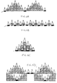
- the invention provides a very flexible type of display apparatus. Exemplary configurations of the display apparatus are shown in Figure 5 and Figure 6A to 6D.
- FIG. 5 there are shown 3 rows 50, 52 and 54 of display apparatus.
- the end display apparatus 50 1 of the first row 50 is arranged so as to have its power-in connection provided by a trailing wire 55.
- the power-out connection of display apparatus 50 1 however is connected to the power-in connection of neighbouring display apparatus 50 2 by means of a flexible connector of the type shown in Figure 3.
- the flexible section allowing neighbouring display apparatuses to have their base units slightly fanned out with respect to one another so that simple curves may be achieved.
- each of the display apparatus 50 2 to 50 9 receive power from the power-out connection of their neighbouring base unit on one side, and transmit power to their neighbour on the other side.
- Display apparatus 50 10 has its power out connection joined, by trailing cable 56 to the first display apparatus 52 1 of the second row 52.
- the display apparatuses 52 1 to 52 9 interconnect with one another in the same manner as was described in relation to the display apparatuses of the first row 50 and then power is conveyed from the end display apparatus 52 9 of the second row 52 up to display apparatuses of a third row 54 by trailing lead 57.
- the end display apparatus 54 6 need not have its power-out connection connected to any other unit, but could, if required, act as a power point for driving any supplementary display apparatus, such as a display carousel or an illuminated stand 58.
- Figures 6A to 6D show arrangements by which individual display apparatus may be placed on different levels and interconnected by trailing wires so as to have a double podium effect as shown in Figure 6A, an alternating effect as shown in Figure 6B, a pyramid type effect as shown in Figure 6C or a multilevel sophisticated effect as shown in Figure 6D.
- trailing wires are shown between individual display apparatuses in Figure 6A to 6D, it will of course be appreciated that such trailing wire may be fed in a discrete manner and concealed if required. Alternatively, they could be made a feature of the apparatus so that the overall display has an appearance resembling interlinked Christmas tree type lights.
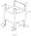
- FIG. 7 shows a display stand 70 upon which individual base units may be arranged to sit.
- the display stand 70 includes a top base unit receiving area 71.
- the receiving area 71 is arranged to be of sufficient dimensions to fit a base unit snugly into.
- the stand has front support legs 72, 73 which have cut away portions 72A, 73A. These cut away portions 72A, 73A are arranged to cooperate with upper front legs, 74, 75 of another stand 70 identical to the first stand 70, so as to allow convenient and secure stacking of stands one upon another.
- a lower rear wall 76 has a cut away portion 76A for cooperating with an upper wall portion 77.
- stands 70 of the type shown in Figure 7 may be arranged so as to provide the different height and display configurations shown in Figures 6A to 6D.
- Figures 6A to 6D show bottles being displayed but, of course, other objects can just as well be displayed on the display apparatus. Also, different types of display apparatus may be intermingled within a particular chain and of course size and configuration of the tiles may be varied according to application. For instance, although basic square tile type display apparatus is shown, triangular formations or other geometric shapes may be used incorporating the same principles.
- Figure 8 shows a base unit 10' upon which there is mounted a sub-housing 80.
- the sub-housing 80 includes a light source 81 which can be arranged to illuminate the rear of an object based upon the base unit 10'.
- the sub-housing 80 includes electrical connections within it, which can cooperate with electrical connections from the base unit 10' to allow power to be fed to the light source 81.
- the base unit 10' may provided with appropriate mechanical mounting means for securely mounting the sub-housing 80 upon it.
Landscapes
- Physics & Mathematics (AREA)
- General Physics & Mathematics (AREA)
- Engineering & Computer Science (AREA)
- Theoretical Computer Science (AREA)
- Business, Economics & Management (AREA)
- Accounting & Taxation (AREA)
- Marketing (AREA)
- Freezers Or Refrigerated Showcases (AREA)
- Illuminated Signs And Luminous Advertising (AREA)
Applications Claiming Priority (2)
| Application Number | Priority Date | Filing Date | Title |
|---|---|---|---|
| GBGB9911266.6A GB9911266D0 (en) | 1999-05-15 | 1999-05-15 | Display apparatus |
| GB9911266 | 1999-05-15 |
Publications (2)
| Publication Number | Publication Date |
|---|---|
| EP1054376A2 true EP1054376A2 (de) | 2000-11-22 |
| EP1054376A3 EP1054376A3 (de) | 2001-01-31 |
Family
ID=10853494
Family Applications (1)
| Application Number | Title | Priority Date | Filing Date |
|---|---|---|---|
| EP00303734A Withdrawn EP1054376A3 (de) | 1999-05-15 | 2000-05-04 | Anzeigevorrichtung |
Country Status (2)
| Country | Link |
|---|---|
| EP (1) | EP1054376A3 (de) |
| GB (1) | GB9911266D0 (de) |
Cited By (3)
| Publication number | Priority date | Publication date | Assignee | Title |
|---|---|---|---|---|
| US7080934B1 (en) | 2002-12-27 | 2006-07-25 | Zarian James R | Illuminated caps for containers and display racks for energizing them |
| US7597448B1 (en) | 2002-12-27 | 2009-10-06 | Zarian James R | Product display system |
| US20160171748A1 (en) * | 2014-12-11 | 2016-06-16 | X-Rite Switzerland GmbH | Method and Apparatus for Digitizing the Appearance of A Real Material |
Family Cites Families (4)
| Publication number | Priority date | Publication date | Assignee | Title |
|---|---|---|---|---|
| US2170641A (en) * | 1937-05-11 | 1939-08-22 | Lancelot Ralph | Illuminated advertising display |
| US5010461A (en) * | 1989-12-11 | 1991-04-23 | Kunio Saotome | Multicolor pressure-sensitive illuminating display platform |
| DE9413806U1 (de) * | 1994-08-30 | 1994-11-03 | Haselhorst, Siegfried, 33102 Paderborn | Untersatz für Gläser |
| FR2749644B1 (fr) * | 1996-06-07 | 1998-09-04 | Barnoin Bernard Francois Charl | Socle eclairant |
-
1999
- 1999-05-15 GB GBGB9911266.6A patent/GB9911266D0/en not_active Ceased
-
2000
- 2000-05-04 EP EP00303734A patent/EP1054376A3/de not_active Withdrawn
Cited By (4)
| Publication number | Priority date | Publication date | Assignee | Title |
|---|---|---|---|---|
| US7080934B1 (en) | 2002-12-27 | 2006-07-25 | Zarian James R | Illuminated caps for containers and display racks for energizing them |
| US7597448B1 (en) | 2002-12-27 | 2009-10-06 | Zarian James R | Product display system |
| US20160171748A1 (en) * | 2014-12-11 | 2016-06-16 | X-Rite Switzerland GmbH | Method and Apparatus for Digitizing the Appearance of A Real Material |
| US10026215B2 (en) * | 2014-12-11 | 2018-07-17 | X-Rite Switzerland GmbH | Method and apparatus for digitizing the appearance of a real material |
Also Published As
| Publication number | Publication date |
|---|---|
| EP1054376A3 (de) | 2001-01-31 |
| GB9911266D0 (en) | 1999-07-14 |
Similar Documents
| Publication | Publication Date | Title |
|---|---|---|
| US8714799B2 (en) | Projection device for variety of light device | |
| US5829862A (en) | Illuminated lighting structure | |
| US10045405B2 (en) | Multiple display-units LED light device has special light effects | |
| US10509304B2 (en) | LED projection light has features | |
| US4989120A (en) | Enhanced lighting for ornaments | |
| US5575098A (en) | Illuminated display apparatus | |
| JPH0850461A (ja) | モジュール式表示組立体 | |
| US7231735B2 (en) | Lighting canopy for advertising sign post | |
| US20070068055A1 (en) | Fordable modular light array | |
| USD399588S (en) | Lighting fixture | |
| US20240230076A1 (en) | Electric lighting systems with removably couplable power devices | |
| EP1054376A2 (de) | Anzeigevorrichtung | |
| US20200099895A1 (en) | LED Projection Seasonal Products | |
| US20050057943A1 (en) | Illumination and reflective devices | |
| US4601924A (en) | Special light effect visual ornaments | |
| US6056419A (en) | Holiday light display device | |
| US3500035A (en) | Electrified packaging ornament | |
| US6210022B1 (en) | Ornamental light display | |
| US6382814B1 (en) | Ornamental light display simulating falling snow | |
| EP2515034B1 (de) | Beleuchtungsvorrichtung | |
| USD324925S (en) | Lamp | |
| US2637926A (en) | Illuminated sign | |
| KR102421115B1 (ko) | 진열 상품에 조명 효과를 부여하는 쇼케이스 | |
| US20100088941A1 (en) | Frame with illuminated picture | |
| CN207720474U (zh) | Led光源的驱动电源组件 |
Legal Events
| Date | Code | Title | Description |
|---|---|---|---|
| PUAI | Public reference made under article 153(3) epc to a published international application that has entered the european phase |
Free format text: ORIGINAL CODE: 0009012 |
|
| AK | Designated contracting states |
Kind code of ref document: A2 Designated state(s): AT BE CH CY DE DK ES FI FR GB GR IE IT LI LU MC NL PT SE |
|
| AX | Request for extension of the european patent |
Free format text: AL;LT;LV;MK;RO;SI |
|
| PUAL | Search report despatched |
Free format text: ORIGINAL CODE: 0009013 |
|
| AK | Designated contracting states |
Kind code of ref document: A3 Designated state(s): AT BE CH CY DE DK ES FI FR GB GR IE IT LI LU MC NL PT SE |
|
| AX | Request for extension of the european patent |
Free format text: AL;LT;LV;MK;RO;SI |
|
| AKX | Designation fees paid | ||
| STAA | Information on the status of an ep patent application or granted ep patent |
Free format text: STATUS: THE APPLICATION IS DEEMED TO BE WITHDRAWN |
|
| 18D | Application deemed to be withdrawn |
Effective date: 20010801 |
|
| REG | Reference to a national code |
Ref country code: DE Ref legal event code: 8566 |